EP3033019B1 - Praeformiertes implantat zur reposition und fixation einer zentrolateralen mittelgesichtsfraktur - Google Patents
Praeformiertes implantat zur reposition und fixation einer zentrolateralen mittelgesichtsfraktur Download PDFInfo
- Publication number
- EP3033019B1 EP3033019B1 EP15715261.2A EP15715261A EP3033019B1 EP 3033019 B1 EP3033019 B1 EP 3033019B1 EP 15715261 A EP15715261 A EP 15715261A EP 3033019 B1 EP3033019 B1 EP 3033019B1
- Authority
- EP
- European Patent Office
- Prior art keywords
- implant
- bone
- segment
- underside
- complementary
- Prior art date
- Legal status (The legal status is an assumption and is not a legal conclusion. Google has not performed a legal analysis and makes no representation as to the accuracy of the status listed.)
- Active
Links
Images



Classifications
-
- A—HUMAN NECESSITIES
- A61—MEDICAL OR VETERINARY SCIENCE; HYGIENE
- A61B—DIAGNOSIS; SURGERY; IDENTIFICATION
- A61B17/00—Surgical instruments, devices or methods
- A61B17/56—Surgical instruments or methods for treatment of bones or joints; Devices specially adapted therefor
- A61B17/58—Surgical instruments or methods for treatment of bones or joints; Devices specially adapted therefor for osteosynthesis, e.g. bone plates, screws or setting implements
- A61B17/68—Internal fixation devices, including fasteners and spinal fixators, even if a part thereof projects from the skin
- A61B17/80—Cortical plates, i.e. bone plates; Instruments for holding or positioning cortical plates, or for compressing bones attached to cortical plates
- A61B17/8061—Cortical plates, i.e. bone plates; Instruments for holding or positioning cortical plates, or for compressing bones attached to cortical plates specially adapted for particular bones
-
- A—HUMAN NECESSITIES
- A61—MEDICAL OR VETERINARY SCIENCE; HYGIENE
- A61B—DIAGNOSIS; SURGERY; IDENTIFICATION
- A61B17/00—Surgical instruments, devices or methods
- A61B17/56—Surgical instruments or methods for treatment of bones or joints; Devices specially adapted therefor
- A61B17/58—Surgical instruments or methods for treatment of bones or joints; Devices specially adapted therefor for osteosynthesis, e.g. bone plates, screws or setting implements
- A61B17/68—Internal fixation devices, including fasteners and spinal fixators, even if a part thereof projects from the skin
- A61B17/80—Cortical plates, i.e. bone plates; Instruments for holding or positioning cortical plates, or for compressing bones attached to cortical plates
- A61B17/8052—Cortical plates, i.e. bone plates; Instruments for holding or positioning cortical plates, or for compressing bones attached to cortical plates immobilised relative to screws by interlocking form of the heads and plate holes, e.g. conical or threaded
- A61B17/8057—Cortical plates, i.e. bone plates; Instruments for holding or positioning cortical plates, or for compressing bones attached to cortical plates immobilised relative to screws by interlocking form of the heads and plate holes, e.g. conical or threaded the interlocking form comprising a thread
-
- A—HUMAN NECESSITIES
- A61—MEDICAL OR VETERINARY SCIENCE; HYGIENE
- A61B—DIAGNOSIS; SURGERY; IDENTIFICATION
- A61B17/00—Surgical instruments, devices or methods
- A61B17/56—Surgical instruments or methods for treatment of bones or joints; Devices specially adapted therefor
- A61B17/58—Surgical instruments or methods for treatment of bones or joints; Devices specially adapted therefor for osteosynthesis, e.g. bone plates, screws or setting implements
- A61B17/68—Internal fixation devices, including fasteners and spinal fixators, even if a part thereof projects from the skin
- A61B17/80—Cortical plates, i.e. bone plates; Instruments for holding or positioning cortical plates, or for compressing bones attached to cortical plates
- A61B17/8061—Cortical plates, i.e. bone plates; Instruments for holding or positioning cortical plates, or for compressing bones attached to cortical plates specially adapted for particular bones
- A61B17/8071—Cortical plates, i.e. bone plates; Instruments for holding or positioning cortical plates, or for compressing bones attached to cortical plates specially adapted for particular bones for the jaw
-
- A—HUMAN NECESSITIES
- A61—MEDICAL OR VETERINARY SCIENCE; HYGIENE
- A61B—DIAGNOSIS; SURGERY; IDENTIFICATION
- A61B17/00—Surgical instruments, devices or methods
- A61B17/56—Surgical instruments or methods for treatment of bones or joints; Devices specially adapted therefor
- A61B17/58—Surgical instruments or methods for treatment of bones or joints; Devices specially adapted therefor for osteosynthesis, e.g. bone plates, screws or setting implements
- A61B17/68—Internal fixation devices, including fasteners and spinal fixators, even if a part thereof projects from the skin
- A61B17/80—Cortical plates, i.e. bone plates; Instruments for holding or positioning cortical plates, or for compressing bones attached to cortical plates
- A61B17/8085—Cortical plates, i.e. bone plates; Instruments for holding or positioning cortical plates, or for compressing bones attached to cortical plates with pliable or malleable elements or having a mesh-like structure, e.g. small strips
-
- A—HUMAN NECESSITIES
- A61—MEDICAL OR VETERINARY SCIENCE; HYGIENE
- A61B—DIAGNOSIS; SURGERY; IDENTIFICATION
- A61B17/00—Surgical instruments, devices or methods
- A61B2017/00004—(bio)absorbable, (bio)resorbable or resorptive
-
- A—HUMAN NECESSITIES
- A61—MEDICAL OR VETERINARY SCIENCE; HYGIENE
- A61B—DIAGNOSIS; SURGERY; IDENTIFICATION
- A61B17/00—Surgical instruments, devices or methods
- A61B17/56—Surgical instruments or methods for treatment of bones or joints; Devices specially adapted therefor
- A61B2017/568—Surgical instruments or methods for treatment of bones or joints; Devices specially adapted therefor produced with shape and dimensions specific for an individual patient
Definitions
- the invention relates to an implant for the reduction and fixation of a centrolateral midface fracture.
- Centrolateral midface fractures such as zygomatic fractures and Le Fort fractures, in particular Le Fort I fractures and Le Fort II fractures, are usually caused by direct force, whereby this is usually a complex fracture in which the ends of the fracture are displaced against each other so that a dislocation of the fragments occurs.
- the WO 2012/079 611 A1 discloses a surgical device for producing an implant by bending, wherein one shape of the device has a patient-specific shape that is individually designed based on anatomical data of the particular patient.
- the object is therefore to provide an implant for improved anatomical reduction and osteosynthesis of a centrolateral midfacial fracture which requires little or no manual adaptation to the anatomical, bone-geometric structures of an implant recipient.
- the implant comprises several preformed segments, preferably three or more preformed segments, the shape of a first segment being designed such that its underside, which is to lie against the bone, also includes the anatomical structure of a partial area of the outside of an upper jawbone (maxilla) is complementary, wherein the shape of a second segment is designed in such a way that its underside, which is to lie against the bone, is complementary to the external anatomical structure of a web area between the upper jaw and zygomatic bone (zygomaticoalveolaris), and the shape of a third segment is designed in such a way that an underside, which is to lie against the bone is complementary to the anatomical structure of at least one outer part of a zygomatic bone (os zygomaticum, os jugale).
- the implant comprises several preformed segments, preferably three or more preformed segments, the shape of a first segment being designed such that its underside, which is to lie against the bone, also includes the anatomical structure of a partial area of the outside
- Outside or outside refers to the side of the skull that is visible from the outside relative to the center of the skull. In the reduced or normal position of the bone fragments, it is provided that all segments of the implant according to the invention are complementary rest against the outside of the bone.
- the implant according to the invention has the particular advantage over previously known implants for reduction and fixation of a centrolateral midface fracture that it is already preformed and is adapted to the anatomical structures of the centrolateral midface bones of the implant recipient.
- previously known implants normally have to be adapted by the surgeon to the anatomical structures of the implant recipient by means of bending during facial surgery. This process is time-consuming and can weaken the material of the implant, especially at the bending points.
- a multiple-fragment fracture is common in a centrolateral midface fracture.
- individual fragments can actually be repositioned and fixed, so that the original, three-dimensional alignment of the centrolateral midfacial bones, in particular the zygomatic bone, is guaranteed.
- the first segment is shaped in such a way that it is shaped complementary to at least one anchor point, preferably to at least two anchor points, on the outside of the maxillary bone and the entire implant according to the invention, in particular the individual segments of the implant according to the invention, based on the first segment can be aligned in a position suitable for the subsequent reduction of bone fragments. That means that a correct alignment of at least the first segment by means of at least one anchor point is sufficient to align the entire implant according to the invention correctly, whereby bone fragments can be repositioned and fixed in their normal position.
- the shape of the first segment can, for example, be shaped in such a way that at least its underside resting on the bone is completely or partially complementary to the anatomical structure of the area which is adjacent above the alveolar process of the upper jaw, in particular the tooth root area (limbus alveolaris).
- the shape of the second segment is shaped in such a way that at least its underside resting on the bone is completely or partially complementary to the external anatomical structure of the lateral zygomatic pillar.
- the shape of the third segment is shaped in such a way that at least its underside resting on the bone is completely or partially complementary to the external anatomical structure of the zygomatic bone prominence (zygomatic process).
- the implant according to the invention can furthermore comprise a fourth and / or a fifth segment, the shape of the fourth segment being designed in such a way that at least its underside resting on the bone with the anatomical structure of at least a partial area of the outside of an upper jaw bone, in particular with the anatomical structure at least of a sub-area of the nasal spine, is completely or partially complementary, and / or the shape of the fifth segment is designed such that at least its underside resting on the bone with the external anatomical structure of at least a sub-area of a paranasal web area between the upper jaw and zygomatic bone is completely or partially is complementary.
- the implant according to the invention By expanding the implant according to the invention by a fourth and / or a fifth segment, it is possible to repair more complex fractures (in particular complex multiple-fragment fractures), for example zygomatic fractures or Le Fort fractures, in particular Le Fort I fractures and Le Fort II fractures, to reduce and fix.
- the alignment of the entire implant is preferably determined on the basis of the first segment and / or the extension of the first segment, which is referred to herein as the fourth segment. It is particularly expedient that the nasal spine serves as the anchor point of the optional fourth segment, the underside of which is completely or partially complementary to the nasal spine.
- the optional fifth segment of the implant according to the invention can, for example, reduce and fix bone fragments that occur in Le Fort fractures, in particular Le Fort I fractures.
- the multi-segment arrangement of the implant according to the invention allows a secure insertion of the preformed implant during an operation, since the implant can be precisely placed in the area of the upper jaw by means of the first and / or the fourth segment and thereby the placement of the other segments, preferably the second and the third segment, in particular the second, third and fifth segment, is established.
- the original positions of the bone fragments are thus predetermined by the individual segments.
- the implant according to the invention is pre-fabricated with all five segments and that the individual segments can be removed as required, for example by the surgeon, for example by means of wire scissors, so that the implant according to the invention comprises exclusively those preformed segments, which are necessary for the reduction and fixation of the respective centrolateral midface fracture.
- the implant according to the invention is plate-shaped and at least partially curved, so that the implant has a three-dimensional design.
- the curvature of the implant is adapted to the anatomical structures of at least partial areas of the centrolateral midface bones.
- at least partial areas of the healthy (in standard position) centrolateral midface bones can be used as a matrix in the production of the inventive Implant can be used.
- certain body parameters such as the size of the skull of the implant recipient, can be taken into account. Children and adolescents usually need a smaller implant than adults. It is provided that a preoperative selection is made in order to select the size of an implant to be inserted. It is also provided that several, preferably at least three, different sizes of a preformed implant (per ethnic group) are provided so that any anatomical structure of the centrolateral midfacial bones of all patients can be restored in their normal position using these implants. Suitable measures to determine the adequate size of an implant according to the invention preoperatively are, for example, the use of computer programs such as the processing of 3D data sets (e.g.
- the ethnic origin and / or the gender of the implant recipient is / are decisive when shaping the implant. This means that for different ethnic groups and / or genders different implants must be manufactured or used for the reduction and fixation of a centrolateral midface fracture.
- the implant according to the invention has a thickness of 0.2 mm to 1.0 mm, preferably 0.3 mm to 0.5 mm, for example. It has the advantage that it can be made thinner than previously known implants, since it does not have to be adapted, or hardly at all, by bending. Because the implant is already preformed, it can be more rigid than other implants.
- the implant according to the invention can be adapted, for example, by bending, preferably only minimally. It can be advantageous that the preformed implant according to the invention further comprises bending points, on the basis of which an at least approximately exact adaptation to the anatomical structures of the implant recipient is possible.
- the implant can also be made from several different materials with different stiffness and flexibility.
- the implant according to the invention has rounded edges.
- the implant comprises a fixation element or, in particular, several fixation elements.
- a fixing element can comprise at least one fixing section, such as a hole or a plurality of holes, in particular a borehole or a plurality of boreholes, with or without an internal thread.
- the fixing element comprises at least one screw or several screws, preferably equipped with an external thread or external thread section that fits into the internal thread of the at least one hole.
- the one fixation element or the fixation elements are designed to fix and reposition at least one bone fragment, preferably several bone fragments.
- the implant according to the invention can be used with or comprises a ThreadLock TS system.
- the ThreadLock TS system is described in detail in the prior art.
- the screws of the ThreadLock TS system include at least two different external threads, with the external thread on the screw head used for locking, for example, corresponding to the internal thread of the at least one hole in the implant.
- the second external thread (bone thread) of the screw By means of the second external thread (bone thread) of the screw, it is screwed into the bone or the bone fragment and thus fixed in the bone or bone fragment.
- the implant according to the invention can be made of titanium and / or a titanium alloy and / or one or more plastics, in particular one or more absorbable materials.
- the front side of the implant according to the invention is designed in such a way that it is adapted to the anatomical structures of the implant recipient. This means that the front and bottom of the implant according to the invention are at least approximately complementary.
- Figure 1 can be seen where the preformed, three-dimensionally shaped, plate-shaped implant 1 consisting of three segments 2, 3 and 4 is placed on the outside of the skull of the implant recipient with the bone fragments in a reduced position.
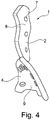
- a corresponding isolated implant is in Figure 4 and Figure 5 shown schematically in a perspective view.
- the shape of the first segment 2 is designed in such a way that at least the underside 9 of the implant resting on the bone is completely or partially complementary to the anatomical structure of at least one outer partial area of an upper jawbone, in particular the tooth root area (limbus alveolaris) 11.
- the shape of the second segment 3 is designed such that at least its underside 9 resting on the bone is completely or partially complementary to the outer anatomical structure of a web area between the upper jaw and the zygomatic bone (zygomaticoalveolar crest) 15, in particular the lateral zygomatic column.
- the shape of the third segment 4 is designed such that at least its underside 9 resting on the bone is completely or partially complementary to the external anatomical structure of at least a partial area of a cheekbone, in particular the cheekbone prominence 13.
- This in Figure 1 The illustrated embodiment is particularly suitable for the reduction and fixation of a zygomatic bone fracture.
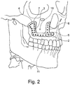
- the preformed implant 10 shown differs from that in FIG Figure 1 depicted embodiment insofar as it further comprises a fourth and a fifth segment 5, 6.
- the shape of the fourth segment 5 is designed such that at least its underside 9 resting on the bone is completely or partially complementary to the external anatomical structure of at least a partial area of an upper jaw, in particular to the anatomical structure of at least a partial area of the nasal spine 12.
- the shape of the fifth segment 6 is also designed in such a way that at least its underside 9 lying on the outside against the bone is completely or partially complementary to the anatomical structure of at least a partial area of a paranasal bar area between the upper jaw and the zygomatic bone.
- the implant 10 comprises an additional anchor point, by means of which the implant 10, in particular on the nasal spine 12 (see FIG Figure 1 ), can be aligned.
- the fifth segment 6 is shaped as a paranasal extension of the implant 10, as a result of which, for example, larger-area fractures can be reduced more easily and better.
- the implant 1, 10 is plate-shaped (with a thickness of 0.3 mm to 0.5 mm) and is at least partially curved. Based on the curvatures, the shape of the segments of the implant 1, 10, in particular the underside 9 of the implant 1, 10, is adapted to the anatomical structure of the centrolateral midface bones (in particular the zygomatic bone) so that the segments are at least approximately complementary on the outside of the respective bone or . Make contact with the bone area. In order to be able to position the implant 1, 10 properly on the skull of the implant recipient, it is provided that the implant 1, 10 is initially aligned by means of the first segment 2 on the tooth root area (limbus alveolaris) 11 in such a way that it is completely or at least approximately complementary to the bone is present.
- the preformed implant 1, 10 thus offers a kind of template to reduce and fix the fragments in their normal position (ideally this is your starting position before the occurrence of the fracture).
- the preformation of the implant 1, 10 according to the invention as a three-dimensional template offers the particular advantage that, in the case of multi-fragment fractures, the individual bone fragments can be repositioned and fixed more quickly and easily, so that the original face shape of the implant recipient, determined by the geometric position of the bone is completely or at least approximately completely recoverable.
- Both embodiments of the implant 1, 10 according to the invention comprise a plurality of fixing elements designed as drill holes with an internal thread 7.
- the implant 1, 10 can be fixed to the bone or the bone fragments by means of screws which are shaped with matching external threads to the internal threads of the drill holes, whereby it can be used for repositioning and fixing the fragments.
- the connection between plate and screw preferably uses different diameters than the fixation between screw and bone.
- the implant 1, 10 according to the invention can preferably be used with the ThreadLock TS system or the implant 1, 10 according to the invention comprises the ThreadLock TS system.
- FIG. 3A the possible course of a pyramidal Le Fort II fracture 16 is indicated by the dashed line - a central midface fracture with a pyramidal fracture of the upper jaw (pyramidal fracture) of the upper jaw mass.
- the fracture line 16 mostly runs along or below the frontomaxillary suture (with or without involvement of the nasal skeleton), through the maxillary frontal process, along the medial wall of the orbit (medial corner of the eye), through the lacrimal bone, through the orbital floor 14, the lower one Orbital edge, through or close to the infraorbital foramen, sloping downward through the anterior wall of the maxillary sinus.
- the fracture line 16 also runs under the zygomatic bone along the pterygomaxillary fissure and through the medial and lateral pterygoid lamina.
- the dashed line shows the possible course of a horizontal midfacial fracture of the Le Fort-I type.
- the fracture line 17 extends from the nasal septum to the lateral edge of the piriformis aperture, horizontally just above the tips of the roots of the maxillary teeth. It mostly crosses below the zygomaticomaxillary suture (the bone suture between Upper jaw and zygomatic bone), crosses the pterygomaxillary suture and further the lateral and medial pterygoid processes (left and / or right halves of the face in each case).
- FIG 3C the possible course of a zygomatic bone fracture (lateral midface fracture) 18 is shown on the basis of the dashed line.
- the fracture line 18 mostly runs along the bone suture (suture) between the zygomatic bone and the frontal bone (sutura zygomaticofrontalis), the lateral wall of the bony eye socket 14 (orbit), along a bone cleft in the floor of the orbit (fissura orbitalis inferior), the foramen infraorbitale (exit point des Infraorbital nerve from the upper jaw (maxilla)), the upper lateral and the rear wall of the maxillary sinus (maxillary sinus).
- the displacement (dislocation) of fragments of the zygomatic bone can take place towards the middle (medially) into the maxillary sinus and orbit as well as downwards (caudally) and backwards (dorsally). Very often, when the fracture lines are surgically exposed, there is a shattered lateral wall of the maxillary sinus.
Landscapes
- Health & Medical Sciences (AREA)
- Orthopedic Medicine & Surgery (AREA)
- Surgery (AREA)
- Life Sciences & Earth Sciences (AREA)
- Heart & Thoracic Surgery (AREA)
- Nuclear Medicine, Radiotherapy & Molecular Imaging (AREA)
- Engineering & Computer Science (AREA)
- Biomedical Technology (AREA)
- Neurology (AREA)
- Medical Informatics (AREA)
- Molecular Biology (AREA)
- Animal Behavior & Ethology (AREA)
- General Health & Medical Sciences (AREA)
- Public Health (AREA)
- Veterinary Medicine (AREA)
- Surgical Instruments (AREA)
- Prostheses (AREA)
Description
- Die Erfindung betrifft ein Implantat zur Reposition und Fixation einer zentrolateralen Mittelgesichtsfraktur.
- Zentrolaterale Mittelgesichtsfrakturen, wie beispielsweise Jochbeinfrakturen und Le Fort-Frakturen, insbesondere Le Fort I-Frakturen und Le Fort II-Frakturen, werden meist durch eine direkte Gewalteinwirkung hervorgerufen, wobei es sich dabei regelmäßig um eine Komplexfraktur handelt, bei welcher die Bruchenden gegeneinander verschoben werden, so dass eine Dislokation der Fragmente auftritt.
- Bei der Therapie einer solchen dislozierten Fraktur ist in der Regel ein chirurgischer Eingriff notwendig, wobei mit Hilfe eines Implantats eine Fixation und Reposition der Knochenfragmente hergestellt wird. Als Implantate werden dabei üblicherweise plane, plattenförmige Osteosyntheseplatten aus Titan oder anderen geeigneten Materialien verwendet, welche in verschiedenen Formen und Stärken erhältlich sind. Diese Titanplatten werden zumeist mit Schrauben an Knochenfragmenten angebracht und bieten daher eine Stütze, damit die Fragmente wieder in ihrer ursprünglichen Lage gehalten werden, um so den Heilungsprozess des Jochbeins zu ermöglichen. Während eines solchen operativen Eingriffs (Osteosynthese) ist es notwendig, dass die plan ausgebildeten Implantate vom behandelten Chirurgen manuell an die anatomischen, knochengeometrischen Strukturen des Implantatempfängers mittels Biegen angepasst werden. Diese individuelle Anpassung des Implantats ist zeitaufwendig und kann dazu führen, dass das Implantat mehrmals angepasst werden muss, bis es schließlich die gewünschte Form angenommen hat bzw. an den anatomischen, knochengeometrischen Strukturen des Implantatempfängers derart anliegt, dass diese adäquat reponiert und fixiert sind und sich daher nicht mehr gegeneinander verschieben können. Ferner kann es aufgrund der Anpassung des Implantats durch Biegen zu einer Vorschwächung, insbesondere an den Biegezonen, kommen.
- Ein weiterer Nachteil vorbekannter planer Osteosyntheseplatten besteht darin, dass diese nur eingeschränkt für die Reposition und Fixation von Trümmerbrüchen (Mehrfragmentfrakturen), insbesondere von zentrolateralen Mittelgesichtsfrakturen Typ V, geeignet sind. Während eines gesichtschirurgischen Eingriffs zur Behandlung eines solchen Trümmerbruchs ist es häufig nicht oder kaum möglich, mittels vorbekannter Implantate alle oder zumindest den Großteil der einzelnen Knochenfragmente derart zu reponieren und/oder zu fixieren, dass die Normpositionen der einzelnen Fragmente vollständig oder zumindest annähernd vollständig wiederherstellbar ist. Daher sind vorbekannte Osteosyntheseplatten grundsätzlich nicht zur Überbrückung von mehrfachen, komplexen Frakturen geeignet
- Gattungsgemäßer Stand der Technik ist aus der
europäischen Patentanmeldung EP 2 698 122 A1 bekannt. Diese offenbart ein orthognatisches Implantat mit einer Brücke und verschiedenen fingerförmigen Segmenten. - Zudem wird in der
WO 2012/079 611 A1 eine chirurgische Vorrichtung zum Herstellen eines Implantats durch Biegen offenbart, wobei eine Form der Vorrichtung eine patientenspezifische Form besitzt, die basierend auf anatomischen Daten des bestimmten Patienten individuell ausgebildet ist. - Weiterhin sind auch die Dokumente
WO 00/66012 A EP 2 201 899 A1 als Stand der Technik anzusehen. - Es besteht daher die Aufgabe, ein Implantat zur verbesserten anatomischen Reposition und Osteosynthese einer zentrolateralen Mittelgesichtsfraktur bereitzustellen, welches keine oder kaum eine manuelle Anpassung an die anatomischen, knochengeometrischen Strukturen eines Implantatempfängers notwendig macht.
- Die der Erfindung zugrunde liegende Aufgabe wird durch die Merkmale aus Anspruch 1 und zwar dadurch gelöst, dass das Implantat mehrere präformierte Segmente, vorzugsweise drei oder mehr präformierte Segmente umfasst, wobei die Form eines ersten Segments derart ausgebildet ist, dass seine am Knochen anzuliegende Unterseite mit der anatomischen Struktur eines Teilbereiches der Außenseite eines Oberkieferknochens (Maxilla) komplementär ist, wobei die Form eines zweiten Segments derart ausgebildet ist, dass seine am Knochen anzuliegende Unterseite mit der außenseitigen anatomischen Struktur eines Stegbereichs zwischen Oberkiefer und Jochbein (Crista zygomaticoalveolaris) komplementär ist, und wobei die Form eines dritten Segments derart ausgebildet ist, dass eine am Knochen anzuliegende Unterseite mit der anatomischen Struktur zumindest eines außenseitigen Teilbereiches eines Jochbeins (Os zygomaticum, Os jugale) komplementär ist.
- Außenseite bzw. außenseitig bezieht sich dabei auf die von außen sichtbare Seite des Schädels relativ zum Schädelmittelpunkt. In reponierter Stellung bzw. Normposition der Knochenfragmente ist vorgesehen, dass alle Segmente, des erfindungsgemäßen Implantats komplementär zur Außenseite des Knochens anliegen.
- Das erfindungsgemäße Implantat hat insbesondere den Vorteil gegenüber vorbekannten Implantaten zur Reposition und Fixation einer zentrolateralen Mittelgesichtsfraktur, dass es bereits präformiert vorliegt und an die anatomischen Strukturen der zentrolateralen Mittelgesichtsknochen des Implantatempfängers angepasst ist. Normalerweise müssen vorbekannte Implantate, wie bereits erwähnt, während eines gesichtschirurgischen Eingriffs durch den Chirurgen mittels Biegen an die anatomischen Strukturen des Implantatempfängers angepasst werden. Dieser Vorgang ist zeitaufwendig und kann das Material des Implantats, insbesondere an den Biegestellen, schwächen.
- Häufig besteht bei einer zentrolateralen Mittelgesichtsfraktur eine Mehrfragmentfraktur. Durch die Vorgabe des erfindungsgemäßen präformierten Implantats lassen sich einzelne Fragmente regelrecht reponieren und fixieren, so dass die ursprüngliche, dreidimensionale Ausrichtung der zentrolateralen Mittelgesichtsknochen, insbesondere des Jochbeins, gewährleistet ist.
- Anhand von Untersuchungen der Schädelform hat sich gezeigt, dass die individuelle Formabweichung im Bereich der zentrolateralen Mittelgesichtsknochen, insbesondere des Jochbeins, nur minimal ist. Daher ist es möglich, ein präformiertes Implantat auszubilden, welches vollständig oder teilweise komplementär zu diesen bei allen Menschen (einer ethnischen Gruppe) ähnlichen anatomischen Strukturen ist. Lediglich die Schädelgröße sowie die ethnische Herkunft des Implantatempfängers müssen bei der Wahl einer bestimmten Implantatgröße berücksichtigt werden. Eine vorgeformte dreidimensionale Ausgestaltung ermöglicht dabei auch bei beidseitigen Gesichtsfrakturen eine adäquate Reposition und Fixation der Knochenfragmente.
- Dabei ist es besonders zweckmäßig, dass das erste Segment derart ausgeformt ist, dass es komplementär zu zumindest einem Ankerpunkt, vorzugsweise zu zumindest zwei Ankerpunkten, der Außenseite des Oberkieferknochens ausgeformt ist und das gesamte erfindungsgemäße Implantat, insbesondere die einzelnen Segmente des erfindungsgemäßen Implantats, anhand des ersten Segmentes in eine für die nachfolgende Reposition von Knochenfragmenten geeignete Lage ausrichtbar ist/sind. Das bedeutet, dass eine korrekte Ausrichtung zumindest des ersten Segmentes mittels zumindest eines Ankerpunktes ausreichend ist, um das gesamte erfindungsgemäße Implantat korrekt auszurichten, wodurch Knochenfragmente in ihrer Normposition reponiert und fixiert werden können. Die Form des ersten Segments kann beispielsweise derart ausgeformt sein, dass wenigstens seine am Knochen anliegende Unterseite mit der anatomischen Struktur des Bereichs, welcher oberhalb des Alveolarfortsatzes des Oberkiefers angrenzt, insbesondere des Zahnwurzelbereichs (Limbus alveolaris), vollständig oder teilweise komplementär ist.
- Es kann vorgesehen sein, dass die Form des zweiten Segments derart ausgeformt ist, dass wenigstens seine am Knochen anliegende Unterseite mit der außenseitigen anatomischen Struktur des lateralen Jochbeinpfeilers vollständig oder teilweise komplementär ist.
- Es kann vorgesehen sein, dass die Form des dritten Segments derart ausgeformt ist, dass wenigstens seine am Knochen anliegende Unterseite mit der außenseitigen anatomischen Struktur der Jochbeinprominenz (Processus zygomaticus) vollständig oder teilweise komplementär ist.
- Das erfindungsgemäße Implantat kann ferner ein viertes und/oder ein fünftes Segment umfassen, wobei die Form des vierten Segments derart ausgebildet ist, dass wenigstens seine am Knochen anliegende Unterseite mit der anatomischen Struktur zumindest eines Teilbereiches der Außenseite eines Oberkieferknochens, insbesondere mit der anatomischen Struktur zumindest eines Teilbereiches der Spina nasalis, vollständig oder teilweise komplementär ist, und/oder wobei die Form des fünften Segments derart ausgebildet ist, dass wenigstens seine am Knochen anliegende Unterseite mit der außenseitigen anatomischen Struktur zumindest eines Teilbereiches eines paranasalen Stegbereichs zwischen Oberkiefer und Jochbein vollständig oder teilweise komplementär ist.
- Durch die Erweiterung des erfindungsgemäßen Implantats um ein viertes und/oder ein fünftes Segment ist es möglich, komplexere Frakturen (insbesondere komplexe Mehrfragmentfrakturen), beispielsweise Jochbeinfrakturen oder Le Fort-Frakturen, insbesondere Le Fort I-Frakturen und Le Fort II-Frakturen, zu reponieren und zu fixieren. Die Ausrichtung des gesamten Implantats wird dabei vorzugsweise anhand des ersten Segments und/oder der Verlängerung des ersten Segments, welche hierin als viertes Segment bezeichnet ist, bestimmt. Es ist insbesondere zweckmäßig, dass die Spina nasalis als Ankerpunkt des optionalen vierten Segments dient, dessen Unterseite zur Spina nasalis vollständig oder teilweise komplementär ist. Durch das optionale fünfte Segment des erfindungsgemäßen Implantats können beispielsweise Knochenfragmente reponiert und fixiert werden, die bei Le Fort-Frakturen, insbesondere Le Fort I-Frakturen, vorkommen.
- Die mehrsegmentige Anordnung des erfindungsgemäßen Implantats erlaubt eine sichere Insertion des präformierten Implantats während einer Operation, da sich das Implantat mittels des ersten und/oder des vierten Segments präzise im Bereich des Oberkiefers platzieren lässt und dadurch die Platzierung der weiteren Segmente, vorzugsweise des zweiten und des dritten Segmentes, insbesondere des zweiten, dritten und fünften Segments, festgelegt wird. Durch die einzelnen Segmente werden somit die ursprünglichen Positionen der Knochenfragmente vorgegeben.
- Es ist vorstellbar, dass das erfindungsgemäße Implantat mit allen fünf Segmenten vorgefertigt vorliegt und dass die einzelnen Segmente, zum Beispiel durch den Chirurgen, je nach Bedarf, beispielsweise mittels einer Drahtschere, entfernbar sind, so dass das erfindungsgemäße Implantat jeweils ausschließlich diejenigen präformierten Segmente umfasst, welche zur Reposition und Fixation der jeweiligen zentrolateralen Mittelgesichtsfraktur notwendig sind.
- Um Knochenfragmente, insbesondere bei Mehrfragmentfrakturen, reponieren und fixieren zu können, ist vorgesehen, dass das erfindungsgemäße Implantat plattenförmig und zumindest teilweise gekrümmt ausgebildet ist, so dass das Implantat eine dreidimensionale Ausbildung aufweist. Die Krümmung des Implantats ist dabei an die anatomischen Strukturen zumindest von Teilbereichen der zentrolateralen Mittelgesichtsknochen angepasst. So können zumindest Teilbereiche der gesunden (in Normposition vorliegenden) zentrolateralen Mittelgesichtsknochen als Matrize bei der Herstellung des erfindungsgemäßen Implantats verwendet werden.
- Zur Determination der jeweiligen Größe des erfindungsgemäßen Implantats bzw. der Implantatsegmente können bestimmte Körperparameter, wie beispielsweise die Schädelgröße des Implantatempfängers, berücksichtigt werden. Kinder und Jugendliche brauchen üblicherweise ein kleineres Implantat als Erwachsene. Dabei ist vorgesehen, dass zur Auswahl der Größe eines einzusetzenden Implantats eine präoperative Auswahl getroffen wird. Es ist ferner vorgesehen, dass mehrere, vorzugsweise zumindest drei, verschiedene Größen eines präformierten Implantats (pro ethnische Gruppe) bereitgestellt sind, so dass anhand dieser Implantate jegliche anatomische Struktur der zentrolateralen Mittelgesichtsknochen aller Patienten in ihrer Normposition wiederherstellbar sind. Geeignete Maßnahmen, um präoperativ die adäquate Größe eines erfindungsgemäßen Implantats zu ermitteln, sind beispielsweise die Verwendung von Computerprogrammen wie zur Verarbeitung von 3D-Datensätzen (zum Beispiel Medtronic, IVS Solutions (Chemnitz), Brainlab (München)), welche durch Computertomografie ermittelt wurden, Vermessung des Augenabstandes, Vermessung des Schädelumfangs oder vorzugsweise Anlegen verschiedener Größen spiegelbildlich ausgeformter Implantate an der intakten Gesichtshälfte des Patienten. Insbesondere mittels des Anlegens verschiedener Größen eines spiegelbildlich ausgeformten Implantats an der intakten Gesichtshälfte kann schnell und einfach ermittelt werden, welche Größe zur Reposition und Fixation einer zentrolateralen Mittelgesichtsfraktur benötigt wird.
- Ferner ist/sind die ethnische Herkunft und/oder das Geschlecht des Implantatempfängers entscheidend bei der Ausformung des Implantats. Das bedeutet, dass für unterschiedliche ethnische Bevölkerungsgruppen und/oder Geschlechter auch unterschiedliche Implantate hergestellt bzw. zur Reposition und Fixation einer zentrolateralen Mittelgesichtsfraktur verwendet werden müssen.
- Das erfindungsgemäße Implantat hat beispielsweise eine Dicke von 0,2 mm bis 1,0 mm, vorzugsweise von 0,3 mm bis 0,5 mm. Es hat den Vorteil, dass es dünner ausgestaltet sein kann als vorbekannte Implantate, da es nicht oder kaum durch Verbiegen angepasst werden muss. Aufgrund dessen, dass das Implantat bereits präformiert ist, kann es eine erhöhte Steifigkeit gegenüber anderen Implantaten haben.
- Es kann vorgesehen sein, dass das erfindungsgemäße Implantat beispielsweise durch Biegen, vorzugsweise lediglich minimal, angepasst werden kann. Dabei kann es vorteilhaft sein, dass das präformierte erfindungsgemäße Implantat weiter Biegestellen umfasst, anhand derer eine zumindest annähernd exakte Anpassung an die anatomischen Strukturen des Implantatempfängers möglich ist. Das Implantat kann zudem auch aus mehreren verschiedenen Materialien mit unterschiedlicher Steifigkeit und Biegsamkeit hergestellt sein.
- Um Irritationen und Verletzungen der Weichteile zu verhindern oder zumindest zu vermindern, weist das erfindungsgemäße Implantat eine abgerundete Berandung auf.
- Damit durch das erfindungsgemäße Implantat eine adäquate Fixation und Reposition einer zentrolateralen Mittelgesichtsfraktur gewährleistet ist, ist vorgesehen, dass das Implantat ein Fixierungselement oder insbesondere mehrere Fixierungselemente umfasst. Ein Fixierungselement kann zumindest einen Fixierungsabschnitt, wie beispielsweise ein Loch oder mehrere Löcher, insbesondere ein Bohrloch oder mehrere Bohrlöcher, mit oder ohne Innengewinde umfassen. Es kann weiter vorgesehen sein, dass das Fixierungselement zumindest eine Schraube oder mehrere Schrauben, vorzugsweise ausgestattet mit einem in das Innengewinde des zumindest einen Loches passenden Außengewindes oder Außengewindeabschnitts, umfasst. Das eine Fixierungselement oder die Fixierungselemente sind zur Fixierung und Reposition zumindest eines Knochenfragments, vorzugsweise mehrerer Knochenfragmente, ausgebildet. Es ist besonders zweckmäßig, wenn das erfindungsgemäße Implantat mit einem ThreadLock TS-System verwendbar ist bzw. dieses umfasst. Das ThreadLock TS-System ist im Stand der Technik ausführlich beschrieben. Die Schrauben des ThreadLock TS-Systems umfassen zumindest zwei unterschiedliche Außengewinde, wobei beispielsweise das zur Verriegelung dienende Außengewinde am Schraubenkopf korrespondierend zum Innengewinde des zumindest einen Loches des Implantats ist. Mittels des zweiten Außengewindes (Knochengewindes) der Schraube wird diese in den Knochen bzw. das Knochenfragment eingeschraubt und somit im Knochen bzw. Knochenfragment fixiert.
- Das erfindungsgemäße Implantat kann aus Titan und/oder einer Titanlegierung und/oder einem oder mehreren Kunststoffen, insbesondere einem oder mehreren resorbierfähigen Materialien, hergestellt sein.
- Es kann ferner vorgesehen sein, dass die Vorderseite des erfindungsgemäßen Implantats derart ausgebildet ist, dass sie an die anatomischen Strukturen des Implantatempfängers angepasst ist. Das heißt, dass die Vorder- und Unterseite des erfindungsgemäßen Implantats zumindest annähernd komplementär ausgebildet sind.
- Die Erfindung wird nun anhand zweier Ausführungsbeispiele näher beschrieben, ist aber nicht auf diese Ausführungsbeispiele beschränkt. Weitere Ausführungsbeispiele ergeben sich durch Kombination der Merkmale einzelner oder mehrerer Schutzansprüche untereinander und/oder mit einzelnen oder mehreren Merkmalen des Ausführungsbeispiels.
- Es zeigt, zum Teil schematisiert:
- Fig. 1
- eine Ausführungsform des erfindungsgemäßen Implantats mit drei Segmenten in ihrer Position am menschlichen Schädel,
- Fig. 2
- eine Ausführungsform des erfindungsgemäßen Implantats mit fünf Segmenten in ihrer Position am menschlichen Schädel,
- Fig. 3
- eine nicht abgeschlossene Auswahl von häufig auftretenden Frakturlinien der zentrolateralen Mittelgesichtsknochen,
- Fig. 4
- eine perspektivische Darstellung der Ausführungsform des erfindungsgemäßen Implantats aus
Fig. 1 , - Fig. 5
- eine perspektivische Darstellung der Ausführungsform des erfindungsgemäßen Implantats aus
Fig. 1 und4 . - Eine im Ganzen als 1 bezeichnete Ausführungsform des erfindungsgemäßen Implantats ist in
Figuren 1 ,4 und5 gezeigt. - In
Figur 1 ist zu sehen, wo das präformierte, dreidimensional ausgeformte, plattenförmige Implantat 1 bestehend aus drei Segmenten 2, 3 und 4 in reponierter Stellung der Knochenfragmente außenseitig am Schädel des Implantatempfängers angelegt ist. - Ein entsprechendes isoliertes Implantat ist in
Figur 4 undFigur 5 schematisiert in perspektivischer Ansicht dargestellt. - Dabei ist die Form des ersten Segments 2, welche derart ausgebildet ist, dass wenigstens die am Knochen anliegende Unterseite 9 des Implantats mit der anatomischen Struktur zumindest eines außenseitigen Teilbereiches eines Oberkieferknochens, insbesondere des Zahnwurzelbereiches (Limbus alveolaris) 11, vollständig oder teilweise komplementär ist. Die Form des zweiten Segments 3 ist derart ausgebildet, dass wenigstens seine am Knochen anliegende Unterseite 9 mit der außenseitigen anatomischen Struktur eines Stegbereichs zwischen Oberkiefer und Jochbein (Crista zygomaticoalveolaris) 15, insbesondere des lateralen Jochbeinpfeilers, vollständig oder teilweise komplementär ist. Ferner ist die Form des dritten Segments 4 derart ausgebildet, dass wenigstens seine am Knochen anliegende Unterseite 9 mit der außenseitigen anatomischen Struktur zumindest eines Teilbereiches eines Jochbeins, insbesondere der Jochbeinprominenz 13, vollständig oder teilweise komplementär ist. Das in
Figur 1 abgebildete Ausführungsbeispiel ist insbesondere zur Reposition und Fixation einer Jochbeinfraktur geeignet. - Das in
Figur 2 dargestellte präformierte Implantat 10 unterscheidet sich von der inFigur 1 abgebildeten Ausführungsform insofern, dass es weiter ein viertes und ein fünftes Segment 5, 6 umfasst. Die Form des vierten Segments 5 ist derart ausgebildet, dass wenigstens seine am Knochen anliegende Unterseite 9 mit der außenseitigen anatomischen Struktur zumindest eines Teilbereiches eines Oberkiefers, insbesondere mit der anatomischen Struktur zumindest eines Teilbereiches der Spina nasalis 12, vollständig oder teilweise komplementär ist. Die Form des fünften Segments 6 ist ferner derart ausgebildet, dass wenigstens seine außenseitig am Knochen anliegende Unterseite 9 mit der anatomischen Struktur zumindest eines Teilbereiches eines paranasalen Stegbereichs zwischen Oberkiefer und Jochbein vollständig oder teilweise komplementär ist. - Die
Figur 2 dargestellte Ausführungsform der Erfindung hat insbesondere den Vorteil, dass damit komplexere Frakturen, wie zum Beispiel Jochbeinfrakturen und Le Fort-Frakturen, insbesondere Le Fort I-Frakturen 17 und Le Fort II-Frakturen 16, gerichtet werden können. Durch das vierte Segment 5 umfasst das Implantat 10 einen zusätzlichen Ankerpunkt, mittels dessen das Implantat 10, insbesondere an der Spina nasalis 12 (sieheFigur 1 ), ausgerichtet werden kann. Das fünfte Segment 6 ist als paranasale Verlängerung des Implantats 10 ausgeformt, wodurch beispielsweise großflächigere Frakturen leichter und besser reponiert werden können. - Das erfindungsgemäße Implantat 1, 10 ist plattenförmig (mit einer Dicke von 0,3 mm bis 0,5 mm) und zumindest teilweise gekrümmt ausgebildet. Anhand der Krümmungen ist die Form der Segmente des Implantats 1, 10, insbesondere der Unterseite 9 des Implantats 1, 10, an die anatomische Struktur der zentrolateralen Mittelgesichtsknochen (insbesondere des Jochbeins) angepasst, so dass die Segmente zumindest annähernd komplementär außenseitig am jeweiligen Knochen bzw. Knochenbereich anliegen. Um das Implantat 1, 10 regelrecht am Schädel des Implantatempfängers positionieren zu können, ist vorgesehen, dass das Implantat 1, 10 zunächst mittels des ersten Segments 2 am Zahnwurzelbereich (Limbus alveolaris) 11 derart ausgerichtet wird, dass es vollständig oder zumindest annähernd komplementär am Knochen anliegt. Durch eine solch adäquate Ausrichtung des ersten Segments 2 und falls vorhanden des vierten Segments 5 ist gewährleistet, dass dann das zweite und das dritte Segment 3, 4 und falls vorhanden das fünfte Segment 6 ebenfalls in ihren vorbestimmten Positionen vorliegen, um somit dem Chirurgen eine Matrize zur Reposition beispielsweise einzelner Fragmente vorzugeben. Somit bietet das präformierte Implantat 1, 10 eine Art Vorlage, um die Fragmente in ihrer Normposition (idealerweise ist das Ihre Ausgangslage vor dem Eintreten der Fraktur) zu reponieren und zu fixieren. Die Präformation des erfindungsgemäßen Implantats 1, 10 als dreidimensionale Vorlage bietet dabei insbesondere den Vorteil, dass man bei Mehrfragmentfrakturen die einzelnen Knochenfragmente schneller und einfacher regelrecht reponieren und fixieren kann, so dass die ursprüngliche, durch die geometrische Position des Knochens bestimmte Gesichtsform des Implantatempfängers vollständig oder zumindest annähernd vollständig wiederherstellbar ist.
- Beide Ausführungsformen des erfindungsgemäßen Implantats 1, 10 umfassen mehrere als Bohrlöcher mit einem Innengewinde 7 ausgebildete Fixierungselemente. Das Implantat 1, 10 kann mittels Schrauben, die mit passenden Außengewinde zu den Innengewinden der Bohrlöcher ausgeformt sind, am Knochen bzw. den Knochenfragmenten fixiert werden, wodurch es zur Reposition und Fixierung der Fragmente verwendet werden kann. Vorzugsweise nutzt die Verbindung zwischen Platte und Schraube unterschiedliche Durchmesser als die Fixierung zwischen Schraube und Knochen. Vorzugsweise ist das erfindungsgemäße Implantat 1, 10 mit dem ThreadLock TS-System verwendbar oder das erfindungsgemäße Implantat 1, 10 umfasst das ThreadLock TS-System.
- In den
Figuren 3A, 3B und 3C sind mehrere potentielle Frakturlinien bei zentrolateralen Mittelgesichtsfrakturen dargestellt. InFigur 3A . ist anhand der gestrichelten Linie der mögliche Verlauf einer pyramidalen Le Fort-II-Fraktur 16 angedeutet - eine zentrale Mittelgesichtsfraktur mit einer pyramidenförmigen Oberkieferabsprengung (Pyramidalfraktur) des Oberkiefermassives. Die Frakturlinie 16 verläuft zumeist entlang oder unterhalb der Sutura frontomaxillaris (mit oder ohne Beteiligung des Nasenskeletts), durch den Processus frontalis maxillae, an der medialen Wand der Orbita (mediale Augenwinkel) entlang, durch das Os lacrimale, durch den Orbitaboden 14, die untere Orbitakante, durch das Foramen infraorbitale oder nahe daran vorbei, schräg nach unten durch die vordere Wand der Kieferhöhle. Die Frakturlinie 16 zieht sich ferner unter dem Jochbein entlang der Fissura pterygomaxillaris und durch die Lamina pterygoidea medialis und lateralis. - In
Figur 3B ist anhand der gestrichelten Linie der mögliche Verlauf einer horizontalen Mittelgesichtsfraktur des Typs Le Fort-I dargestellt. Bei der horizontalen Le-Fort-I-Fraktur reicht die Frakturlinie 17 von der Nasenscheidewand zur lateralen Kante der Apertura piriformis, horizontal knapp oberhalb der Wurzelspitzen der Oberkieferzähne. Sie kreuzt zumeist unterhalb der Sutura zygomaticomaxillaris (der Knochennaht zwischen Oberkiefer und Jochbein), quert die Sutura pterygomaxillaris und weiter die Processus pterygoidei lateralis und medialis (jeweils linke und/oder rechte Gesichtshälfte). - In
Figur 3C ist anhand der gestrichelten Linie der mögliche Verlauf einer Jochbeinfraktur (lateralen Mittelgesichtsfraktur) 18 dargestellt. Die Frakturlinie 18 verläuft zumeist entlang der Knochennaht (Sutur) zwischen Jochbein und Stirnbein (Sutura zygomaticofrontalis), der seitlichen Wand der knöchernen Augenhöhle 14 (Orbita), entlang einer Knochenspalte im Boden der Orbita (Fissura orbitalis inferior), dem Foramen infraorbitale (Austrittspunkt des Nervus infraorbitalis aus dem Oberkiefer (Maxilla)), der oberen seitlichen und die hinteren Wand der Kieferhöhle (Sinus maxillaris). - Die Verlagerung (Dislokation) von Bruchstücken des Jochbeins kann zur Mitte hin (nach medial) in die Kieferhöhle und Orbita hinein sowie nach unten (kaudal) und hinten (dorsal) erfolgen. Sehr oft liegt bei der operativen Freilegung der Frakturlinien eine zertrümmerte seitliche (laterale) Wand der Kieferhöhle vor.
- In den
Figuren 3A, 3B und 3C sind ferner die Jochbeinprominenz (Processus zygomaticus) 13, der Stegbereichs zwischen Oberkiefer und Jochbein (Crista zygomaticoalveolaris) 15, der Zahnwurzelbereich (Limbus alveolaris) 11 und die Spina nasalis 12 angedeutet.
Claims (10)
- Implantat (1, 10) zur Reposition und Fixation einer zentrolateralen Mittelgesichtsfraktur wobei das Implantat (1, 10) mehrere präformierte Segmente umfasst, wobei die Form eines ersten Segments (2), welche sich aus dem Abgleich der Schädelgröße und der ethnischen Herkunft eines Implantatempfängers ergibt, derart ausgebildet ist, dass seine am Knochen anzuliegende Unterseite (9) mit der anatomischen Struktur eines Teilbereiches der Außenseite eines Oberkieferknochens komplementär ist, wobei die Form eines zweiten Segments (3), welche sich aus dem Abgleich der Schädelgröße und der ethnischen Herkunft des Implantatempfängers ergibt, derart ausgebildet ist, dass seine am Knochen anzuliegende Unterseite (9) mit der außenseitigen anatomischen Struktur eines Stegbereichs zwischen Oberkiefer und Jochbein komplementär ist, und wobei die Form eines dritten Segments (4), welche sich aus dem Abgleich der Schädelgröße und der ethnischen Herkunft des Implantatempfängers ergibt, derart ausgebildet ist, dass seine am Knochen anzuliegende Unterseite (9) mit der anatomischen Struktur zumindest eines außenseitigen Teilbereiches eines Jochbeins komplementär ist, wobei das Implantat (1, 10) plattenförmig ausgestaltet ist und eine abgerundete Berandung aufweist.
- Implantat (1, 10) nach Anspruch 1, dadurch gekennzeichnet, dass die Form des ersten Segments (2) derart ausgeformt ist, dass seine am Knochen anzuliegende Unterseite (9) mit der anatomischen Struktur des Bereichs, welcher oberhalb des Alveolar Fortsatzes des Oberkiefers angrenzt komplementär ist.
- Implantat (1, 10) nach Anspruch 1 oder 2, dadurch gekennzeichnet, dass die Form des zweiten Segments (3) derart ausgeformt ist, dass seine am Knochen anzuliegende Unterseite (9) mit der anatomischen Struktur des lateralen Jochbeinpfeilers komplementär ist.
- Implantat (1, 10) nach einem der Ansprüche 1 bis 3, dadurch gekennzeichnet, dass die Form des dritten (4) Segments derart ausgeformt ist, dass seine am Knochen anzuliegende Unterseite (9) mit der anatomischen Struktur der Jochbeinprominenz komplementär ist.
- Implantat (1, 10) nach einem der Ansprüche 1 bis 4, dadurch gekennzeichnet, dass das Implantat (1, 10) ein viertes Segment (5) umfasst, wobei die Form des vierten Segments (5), welche sich aus dem Abgleich der Schädelgröße und der ethnischen Herkunft eines Implantatempfängers ergibt, derart ausgebildet ist, dass seine am Knochen anzuliegende Unterseite (9) mit der anatomischen Struktur eines Teilbereiches der Außenseite eines Oberkieferknochens vollständig oder teilweise komplementär ist, und/oder dass das Implantat (1, 10) ein fünftes Segment (6) umfasst, wobei die Form des fünften Segments (6), welche sich aus dem Abgleich der Schädelgröße und der ethnischen Herkunft eines Implantatempfängers ergibt, derart ausgebildet ist, dass seine am Knochen anzuliegende Unterseite (9) mit der außenseitigen anatomischen Struktur eines Teilbereiches eines paranasalen Stegbereichs zwischen Oberkiefer und Jochbein komplementär ist.
- Implantat (1, 10) nach einem der Ansprüche 1 bis 5, dadurch gekennzeichnet, dass zur Determination der jeweiligen Größe der Implantatsegmente die Schädelgröße des Implantatempfängers berücksichtigt wird, wobei drei Größen eines präformierten Implantats pro ethnische Gruppe bereitgestellt sind, sodass anhand dieser Implantate jegliche anatomische Struktur der zentrolateralen Mittelgesichtsknochen wiederherstellbar sind.
- Implantat (1, 10) nach einem der Ansprüche 1 bis 6, dadurch gekennzeichnet, dass das Implantat (1, 10) ein Fixierungselement oder mehrere Fixierungselemente umfasst, wobei das eine Fixierungselement oder die Fixierungselemente einen Fixierungsabschnitt oder mehrere Fixierungsabschnitte, vorzugsweise ein Loch oder mehrere Löcher (7), insbesondere mit einem Innengewinde oder mehreren Innengewinden, und zumindest eine Schraube oder mehrere Schrauben, vorzugsweise ausgestattet mit zumindest einem in das Innengewinde des zumindest einen Loches (7) passenden Außengewindes oder Außengewindeabschnitts, umfasst, und wobei das zumindest eine Fixierungselement oder die Fixierungselemente zur Fixierung und Reposition zumindest eines Knochenfragments, vorzugsweise mehrerer Knochenfragmente, ausgebildet ist oder sind.
- Implantat (1, 10) nach einem der Ansprüche 1 bis 7, dadurch gekennzeichnet, dass das Implantat (1, 10) aus Titan und/oder einer Titanlegierung und/oder einem oder mehreren Kunststoffen, insbesondere einem oder mehreren resorbierfähigen Materialien, hergestellt ist.
- Implantat (1, 10) nach einem der Ansprüche 1 bis 8, dadurch gekennzeichnet, dass die Vorderseite (8) des Implantats (1, 10) derart ausgebildet ist, dass sie an die außenseitigen anatomischen Strukturen des Implantatempfängers angepasst ist und somit die Vorderseite (8) und die Unterseite (9) komplementär ausgebildet sind.
- Implantat (1, 10) nach einem der Ansprüche 1 bis 9, dadurch gekennzeichnet, dass das Implantat (1, 10) eine Dicke von 0,2 mm bis 1,5 mm, vorzugsweise von 0,3 mm bis 0,7 mm aufweist.
Applications Claiming Priority (3)
| Application Number | Priority Date | Filing Date | Title |
|---|---|---|---|
| DE102014005346.6A DE102014005346A1 (de) | 2014-04-11 | 2014-04-11 | Präformiertes lmplantat zur Reposition und Fixation einer zentrolateralen Mittelgesichtsfraktur |
| DE201420103858 DE202014103858U1 (de) | 2014-04-11 | 2014-04-11 | Präformiertes Implantat zur Reposition und Fixation einer zentrolateralen Mittelgesichtsfraktur |
| PCT/EP2015/057738 WO2015155296A1 (de) | 2014-04-11 | 2015-04-09 | Praeformiertes implantat zur reposition und fixation einer zentrolateralen mittelgesichtsfraktur |
Publications (2)
| Publication Number | Publication Date |
|---|---|
| EP3033019A1 EP3033019A1 (de) | 2016-06-22 |
| EP3033019B1 true EP3033019B1 (de) | 2021-08-18 |
Family
ID=52823642
Family Applications (1)
| Application Number | Title | Priority Date | Filing Date |
|---|---|---|---|
| EP15715261.2A Active EP3033019B1 (de) | 2014-04-11 | 2015-04-09 | Praeformiertes implantat zur reposition und fixation einer zentrolateralen mittelgesichtsfraktur |
Country Status (7)
| Country | Link |
|---|---|
| EP (1) | EP3033019B1 (de) |
| CN (1) | CN106163435B (de) |
| BR (1) | BR112016023426B1 (de) |
| DE (1) | DE102014005346A1 (de) |
| ES (1) | ES2892484T3 (de) |
| RU (1) | RU2699624C2 (de) |
| WO (1) | WO2015155296A1 (de) |
Families Citing this family (8)
| Publication number | Priority date | Publication date | Assignee | Title |
|---|---|---|---|---|
| DE102015112774B4 (de) | 2015-08-04 | 2019-06-13 | Karl Leibinger Medizintechnik Gmbh & Co. Kg | Mobile Implantatsproduktionseinheit |
| DE102015122793A1 (de) * | 2015-12-23 | 2017-06-29 | Karl Leibinger Medizintechnik Gmbh & Co. Kg | Implantat zur Knochenverstärkung mit Bohrvektorvorgabeloch und Umgriffsplatte für Kieferersatz sowie Implantatherstellverfahren |
| CN107374785B (zh) * | 2017-08-02 | 2019-04-05 | 吉林大学 | 一种眶壁爆裂性骨折钛网的预制作方法 |
| CN108542481A (zh) * | 2018-05-11 | 2018-09-18 | 山东大学齐鲁医院 | 一种颧骨骨折外固定愈合用面具及固定愈合系统 |
| CN112656567B (zh) * | 2020-12-18 | 2022-11-08 | 上海交通大学医学院附属第九人民医院 | 一种严重颌面骨折外固定头盔的制作方法 |
| CN113180810B (zh) * | 2021-04-06 | 2023-04-07 | 四川大学 | 颧骨颧弓切开内推整形手术用接骨板 |
| CN113180776B (zh) * | 2021-04-21 | 2023-01-10 | 四川大学 | 颧骨颧弓整形手术用截骨导板及内推导板生成方法 |
| DE102024116468A1 (de) * | 2024-06-12 | 2025-12-18 | Karl Leibinger Asset Management Gmbh & Co. Kg | Implantat zur abstützung einer oberkiefer-zahnprothese am schädelknochen |
Citations (2)
| Publication number | Priority date | Publication date | Assignee | Title |
|---|---|---|---|---|
| EP2201899A1 (de) * | 2008-12-23 | 2010-06-30 | Hibrand Anstalt | Instrument zu Operation einer Augenhöhlenbodenfraktur, Satz aus einer Mehrzahl solcher Instrumente und Verfahren zur Herstellung eines solchen Instruments |
| WO2012079611A1 (en) * | 2010-12-17 | 2012-06-21 | Stryker Leibinger Gmbh & Co. Kg | Surgical device for bending an implant and implant system comprising the device |
Family Cites Families (8)
| Publication number | Priority date | Publication date | Assignee | Title |
|---|---|---|---|---|
| US5690631A (en) * | 1996-09-11 | 1997-11-25 | Walter Lorenz Surgical, Inc. | Multi-configurable plating system |
| ATE286678T1 (de) * | 1999-05-03 | 2005-01-15 | Medartis Ag | Verblockbare knochenplatte |
| RU2202302C2 (ru) * | 2000-10-04 | 2003-04-20 | Закрытое акционерное общество "КОНМЕТ Инкорпорейтед" | Пластина рыбальченко для реконструкции поврежденных костных структур скулоглазничноверхнечелюстного комплекса и способ реконструкции поврежденных костных структур скулоглазничноверхнечелюстного комплекса с ее использованием |
| US7909610B1 (en) * | 2006-12-21 | 2011-03-22 | Amato Craniofacial Engineering, LLC | Computer-aided system of orthopedic surgery |
| CN201324285Y (zh) * | 2008-11-28 | 2009-10-14 | 常州亨杰医疗器械有限公司 | 一种桡骨远端外侧成角固定接骨板 |
| KR101687053B1 (ko) * | 2010-04-29 | 2016-12-15 | 신세스 게엠바하 | 악교정 임플란트 및 그 이용 방법 |
| CN201759662U (zh) * | 2010-08-23 | 2011-03-16 | 枣庄矿业集团滕南医院 | 髋臼骨折固定板 |
| RU2489981C1 (ru) * | 2012-04-02 | 2013-08-20 | федеральное государственное бюджетное учреждение "Центральный научно-исследовательский институт стоматологии и челюстно-лицевой хирургии" Министерства здравоохранения Российской Федерации | Минипластина l-образной формы для остеосинтеза верхней челюсти после остеотомии |
-
2014
- 2014-04-11 DE DE102014005346.6A patent/DE102014005346A1/de not_active Withdrawn
-
2015
- 2015-04-09 BR BR112016023426-0A patent/BR112016023426B1/pt active IP Right Grant
- 2015-04-09 CN CN201580018925.1A patent/CN106163435B/zh active Active
- 2015-04-09 ES ES15715261T patent/ES2892484T3/es active Active
- 2015-04-09 WO PCT/EP2015/057738 patent/WO2015155296A1/de not_active Ceased
- 2015-04-09 EP EP15715261.2A patent/EP3033019B1/de active Active
- 2015-04-09 RU RU2016143577A patent/RU2699624C2/ru active
Patent Citations (2)
| Publication number | Priority date | Publication date | Assignee | Title |
|---|---|---|---|---|
| EP2201899A1 (de) * | 2008-12-23 | 2010-06-30 | Hibrand Anstalt | Instrument zu Operation einer Augenhöhlenbodenfraktur, Satz aus einer Mehrzahl solcher Instrumente und Verfahren zur Herstellung eines solchen Instruments |
| WO2012079611A1 (en) * | 2010-12-17 | 2012-06-21 | Stryker Leibinger Gmbh & Co. Kg | Surgical device for bending an implant and implant system comprising the device |
Also Published As
| Publication number | Publication date |
|---|---|
| BR112016023426A2 (pt) | 2017-08-15 |
| DE102014005346A1 (de) | 2015-10-15 |
| CN106163435B (zh) | 2019-10-22 |
| EP3033019A1 (de) | 2016-06-22 |
| CN106163435A (zh) | 2016-11-23 |
| WO2015155296A1 (de) | 2015-10-15 |
| RU2699624C2 (ru) | 2019-09-06 |
| ES2892484T3 (es) | 2022-02-04 |
| RU2016143577A (ru) | 2018-05-11 |
| BR112016023426B1 (pt) | 2021-11-09 |
| RU2016143577A3 (de) | 2018-11-27 |
Similar Documents
| Publication | Publication Date | Title |
|---|---|---|
| EP3033019A1 (de) | Praeformiertes implantat zur reposition und fixation einer zentrolateralen mittelgesichtsfraktur | |
| DE69738301T2 (de) | Wirbelsäulendistraktionsimplantat | |
| DE69838851T2 (de) | Wirbelsäulendistraktionsimplantat | |
| EP3294168B1 (de) | Orthognatisches säge- und positionierungsimplantat | |
| DE69620930T2 (de) | Platte und Stift | |
| EP2750617B1 (de) | Anatomisch angepasste, plantare knochenplatte sowie knochenplattensystem | |
| EP1901671B1 (de) | Osteosyntheseplatte mit schräg zur plattenebene verlaufenden durchgangsöffnungen | |
| DE112008002307B4 (de) | Fixateur für den Bügel zur Reparatur einer Trichterbrust | |
| DE4004941A1 (de) | System fuer die durchfuehrung chirurgischer eingriffe, beispielsweise bei der behandlung von bruechen der wirbelsaeule, oder von degenerativen oder geschwulstschaedigungen | |
| EP1691701A1 (de) | Osteosyntheseplatten-set | |
| DE102006059225A1 (de) | Medizinische Einrichtung zur Lagebestimmung von intrakorporalen Implantaten | |
| DE112010003941T5 (de) | Knochenpiattensystem und relevante Verfahren | |
| DE29909025U1 (de) | Osteosynthetische Knochenplatte | |
| EP1684651A1 (de) | Platte zum stabilisieren distaler radiusfrakturen | |
| EP0347874A2 (de) | Vorrichtung zum Verbinden eines, insbesondere im Bereich des Oberschenkelhalses, gebrochenen Knochens | |
| EP3393376B1 (de) | Implantat zur knochenverstärkung mit bohrvektorvorgabeloch und umgriffsplatte für kieferersatz sowie implantatherstellverfahren | |
| DE102016105230A1 (de) | Stabilisierungsstruktur zur Stabilisierung oder fixierung von Sternoclavikulargelenken | |
| WO2008040707A2 (de) | Vorrichtung zum umformen von knochen | |
| DE3114872C2 (de) | Implantat zur Korrektur von Wirbelsäulenverkrümmungen | |
| DE212016000275U1 (de) | Vorrichtung zur Verriegelung einer externen Befestigung zum Behandeln einer Schienbeinfraktur | |
| DE202014103858U1 (de) | Präformiertes Implantat zur Reposition und Fixation einer zentrolateralen Mittelgesichtsfraktur | |
| EP4197466B1 (de) | Knochenplatte, chirurgische sets und rekonstruktionssets | |
| DE60117955T2 (de) | Chirurgisches Instrument zur Fixierung gebrochener Gesichtsknochen | |
| EP3354226B1 (de) | Distraktor, insbesondere oberkiefer-distraktor | |
| WO2003096914A1 (de) | Vorrichtung zum einrichten einer menschlichen oder tierischen wirbelsäule und befestigungselement hierfür |
Legal Events
| Date | Code | Title | Description |
|---|---|---|---|
| PUAI | Public reference made under article 153(3) epc to a published international application that has entered the european phase |
Free format text: ORIGINAL CODE: 0009012 |
|
| 17P | Request for examination filed |
Effective date: 20160318 |
|
| AK | Designated contracting states |
Kind code of ref document: A1 Designated state(s): AL AT BE BG CH CY CZ DE DK EE ES FI FR GB GR HR HU IE IS IT LI LT LU LV MC MK MT NL NO PL PT RO RS SE SI SK SM TR |
|
| AX | Request for extension of the european patent |
Extension state: BA ME |
|
| STAA | Information on the status of an ep patent application or granted ep patent |
Free format text: STATUS: EXAMINATION IS IN PROGRESS |
|
| 17Q | First examination report despatched |
Effective date: 20170203 |
|
| DAV | Request for validation of the european patent (deleted) | ||
| DAX | Request for extension of the european patent (deleted) | ||
| GRAP | Despatch of communication of intention to grant a patent |
Free format text: ORIGINAL CODE: EPIDOSNIGR1 |
|
| STAA | Information on the status of an ep patent application or granted ep patent |
Free format text: STATUS: GRANT OF PATENT IS INTENDED |
|
| INTG | Intention to grant announced |
Effective date: 20210311 |
|
| GRAS | Grant fee paid |
Free format text: ORIGINAL CODE: EPIDOSNIGR3 |
|
| GRAA | (expected) grant |
Free format text: ORIGINAL CODE: 0009210 |
|
| STAA | Information on the status of an ep patent application or granted ep patent |
Free format text: STATUS: THE PATENT HAS BEEN GRANTED |
|
| AK | Designated contracting states |
Kind code of ref document: B1 Designated state(s): AL AT BE BG CH CY CZ DE DK EE ES FI FR GB GR HR HU IE IS IT LI LT LU LV MC MK MT NL NO PL PT RO RS SE SI SK SM TR |
|
| REG | Reference to a national code |
Ref country code: GB Ref legal event code: FG4D Free format text: NOT ENGLISH |
|
| REG | Reference to a national code |
Ref country code: CH Ref legal event code: EP |
|
| REG | Reference to a national code |
Ref country code: DE Ref legal event code: R096 Ref document number: 502015015071 Country of ref document: DE |
|
| REG | Reference to a national code |
Ref country code: IE Ref legal event code: FG4D Free format text: LANGUAGE OF EP DOCUMENT: GERMAN Ref country code: AT Ref legal event code: REF Ref document number: 1420922 Country of ref document: AT Kind code of ref document: T Effective date: 20210915 |
|
| REG | Reference to a national code |
Ref country code: LT Ref legal event code: MG9D |
|
| REG | Reference to a national code |
Ref country code: NL Ref legal event code: MP Effective date: 20210818 |
|
| PG25 | Lapsed in a contracting state [announced via postgrant information from national office to epo] |
Ref country code: LT Free format text: LAPSE BECAUSE OF FAILURE TO SUBMIT A TRANSLATION OF THE DESCRIPTION OR TO PAY THE FEE WITHIN THE PRESCRIBED TIME-LIMIT Effective date: 20210818 Ref country code: BG Free format text: LAPSE BECAUSE OF FAILURE TO SUBMIT A TRANSLATION OF THE DESCRIPTION OR TO PAY THE FEE WITHIN THE PRESCRIBED TIME-LIMIT Effective date: 20211118 Ref country code: NO Free format text: LAPSE BECAUSE OF FAILURE TO SUBMIT A TRANSLATION OF THE DESCRIPTION OR TO PAY THE FEE WITHIN THE PRESCRIBED TIME-LIMIT Effective date: 20211118 Ref country code: PT Free format text: LAPSE BECAUSE OF FAILURE TO SUBMIT A TRANSLATION OF THE DESCRIPTION OR TO PAY THE FEE WITHIN THE PRESCRIBED TIME-LIMIT Effective date: 20211220 Ref country code: FI Free format text: LAPSE BECAUSE OF FAILURE TO SUBMIT A TRANSLATION OF THE DESCRIPTION OR TO PAY THE FEE WITHIN THE PRESCRIBED TIME-LIMIT Effective date: 20210818 Ref country code: RS Free format text: LAPSE BECAUSE OF FAILURE TO SUBMIT A TRANSLATION OF THE DESCRIPTION OR TO PAY THE FEE WITHIN THE PRESCRIBED TIME-LIMIT Effective date: 20210818 Ref country code: SE Free format text: LAPSE BECAUSE OF FAILURE TO SUBMIT A TRANSLATION OF THE DESCRIPTION OR TO PAY THE FEE WITHIN THE PRESCRIBED TIME-LIMIT Effective date: 20210818 Ref country code: HR Free format text: LAPSE BECAUSE OF FAILURE TO SUBMIT A TRANSLATION OF THE DESCRIPTION OR TO PAY THE FEE WITHIN THE PRESCRIBED TIME-LIMIT Effective date: 20210818 |
|
| REG | Reference to a national code |
Ref country code: ES Ref legal event code: FG2A Ref document number: 2892484 Country of ref document: ES Kind code of ref document: T3 Effective date: 20220204 |
|
| PG25 | Lapsed in a contracting state [announced via postgrant information from national office to epo] |
Ref country code: PL Free format text: LAPSE BECAUSE OF FAILURE TO SUBMIT A TRANSLATION OF THE DESCRIPTION OR TO PAY THE FEE WITHIN THE PRESCRIBED TIME-LIMIT Effective date: 20210818 Ref country code: LV Free format text: LAPSE BECAUSE OF FAILURE TO SUBMIT A TRANSLATION OF THE DESCRIPTION OR TO PAY THE FEE WITHIN THE PRESCRIBED TIME-LIMIT Effective date: 20210818 Ref country code: GR Free format text: LAPSE BECAUSE OF FAILURE TO SUBMIT A TRANSLATION OF THE DESCRIPTION OR TO PAY THE FEE WITHIN THE PRESCRIBED TIME-LIMIT Effective date: 20211119 |
|
| PG25 | Lapsed in a contracting state [announced via postgrant information from national office to epo] |
Ref country code: NL Free format text: LAPSE BECAUSE OF FAILURE TO SUBMIT A TRANSLATION OF THE DESCRIPTION OR TO PAY THE FEE WITHIN THE PRESCRIBED TIME-LIMIT Effective date: 20210818 |
|
| PG25 | Lapsed in a contracting state [announced via postgrant information from national office to epo] |
Ref country code: DK Free format text: LAPSE BECAUSE OF FAILURE TO SUBMIT A TRANSLATION OF THE DESCRIPTION OR TO PAY THE FEE WITHIN THE PRESCRIBED TIME-LIMIT Effective date: 20210818 |
|
| REG | Reference to a national code |
Ref country code: DE Ref legal event code: R097 Ref document number: 502015015071 Country of ref document: DE |
|
| PG25 | Lapsed in a contracting state [announced via postgrant information from national office to epo] |
Ref country code: SM Free format text: LAPSE BECAUSE OF FAILURE TO SUBMIT A TRANSLATION OF THE DESCRIPTION OR TO PAY THE FEE WITHIN THE PRESCRIBED TIME-LIMIT Effective date: 20210818 Ref country code: SK Free format text: LAPSE BECAUSE OF FAILURE TO SUBMIT A TRANSLATION OF THE DESCRIPTION OR TO PAY THE FEE WITHIN THE PRESCRIBED TIME-LIMIT Effective date: 20210818 Ref country code: RO Free format text: LAPSE BECAUSE OF FAILURE TO SUBMIT A TRANSLATION OF THE DESCRIPTION OR TO PAY THE FEE WITHIN THE PRESCRIBED TIME-LIMIT Effective date: 20210818 Ref country code: EE Free format text: LAPSE BECAUSE OF FAILURE TO SUBMIT A TRANSLATION OF THE DESCRIPTION OR TO PAY THE FEE WITHIN THE PRESCRIBED TIME-LIMIT Effective date: 20210818 Ref country code: CZ Free format text: LAPSE BECAUSE OF FAILURE TO SUBMIT A TRANSLATION OF THE DESCRIPTION OR TO PAY THE FEE WITHIN THE PRESCRIBED TIME-LIMIT Effective date: 20210818 Ref country code: AL Free format text: LAPSE BECAUSE OF FAILURE TO SUBMIT A TRANSLATION OF THE DESCRIPTION OR TO PAY THE FEE WITHIN THE PRESCRIBED TIME-LIMIT Effective date: 20210818 |
|
| PLBE | No opposition filed within time limit |
Free format text: ORIGINAL CODE: 0009261 |
|
| STAA | Information on the status of an ep patent application or granted ep patent |
Free format text: STATUS: NO OPPOSITION FILED WITHIN TIME LIMIT |
|
| 26N | No opposition filed |
Effective date: 20220519 |
|
| PG25 | Lapsed in a contracting state [announced via postgrant information from national office to epo] |
Ref country code: SI Free format text: LAPSE BECAUSE OF FAILURE TO SUBMIT A TRANSLATION OF THE DESCRIPTION OR TO PAY THE FEE WITHIN THE PRESCRIBED TIME-LIMIT Effective date: 20210818 |
|
| REG | Reference to a national code |
Ref country code: CH Ref legal event code: PL |
|
| REG | Reference to a national code |
Ref country code: BE Ref legal event code: MM Effective date: 20220430 |
|
| PG25 | Lapsed in a contracting state [announced via postgrant information from national office to epo] |
Ref country code: MC Free format text: LAPSE BECAUSE OF FAILURE TO SUBMIT A TRANSLATION OF THE DESCRIPTION OR TO PAY THE FEE WITHIN THE PRESCRIBED TIME-LIMIT Effective date: 20210818 Ref country code: LU Free format text: LAPSE BECAUSE OF NON-PAYMENT OF DUE FEES Effective date: 20220409 Ref country code: LI Free format text: LAPSE BECAUSE OF NON-PAYMENT OF DUE FEES Effective date: 20220430 Ref country code: CH Free format text: LAPSE BECAUSE OF NON-PAYMENT OF DUE FEES Effective date: 20220430 |
|
| PG25 | Lapsed in a contracting state [announced via postgrant information from national office to epo] |
Ref country code: BE Free format text: LAPSE BECAUSE OF NON-PAYMENT OF DUE FEES Effective date: 20220430 |
|
| PG25 | Lapsed in a contracting state [announced via postgrant information from national office to epo] |
Ref country code: IE Free format text: LAPSE BECAUSE OF NON-PAYMENT OF DUE FEES Effective date: 20220409 |
|
| REG | Reference to a national code |
Ref country code: AT Ref legal event code: MM01 Ref document number: 1420922 Country of ref document: AT Kind code of ref document: T Effective date: 20220409 |
|
| P01 | Opt-out of the competence of the unified patent court (upc) registered |
Effective date: 20230605 |
|
| PG25 | Lapsed in a contracting state [announced via postgrant information from national office to epo] |
Ref country code: AT Free format text: LAPSE BECAUSE OF NON-PAYMENT OF DUE FEES Effective date: 20220409 |
|
| PG25 | Lapsed in a contracting state [announced via postgrant information from national office to epo] |
Ref country code: HU Free format text: LAPSE BECAUSE OF FAILURE TO SUBMIT A TRANSLATION OF THE DESCRIPTION OR TO PAY THE FEE WITHIN THE PRESCRIBED TIME-LIMIT; INVALID AB INITIO Effective date: 20150409 |
|
| PG25 | Lapsed in a contracting state [announced via postgrant information from national office to epo] |
Ref country code: MK Free format text: LAPSE BECAUSE OF FAILURE TO SUBMIT A TRANSLATION OF THE DESCRIPTION OR TO PAY THE FEE WITHIN THE PRESCRIBED TIME-LIMIT Effective date: 20210818 Ref country code: CY Free format text: LAPSE BECAUSE OF FAILURE TO SUBMIT A TRANSLATION OF THE DESCRIPTION OR TO PAY THE FEE WITHIN THE PRESCRIBED TIME-LIMIT Effective date: 20210818 |
|
| PG25 | Lapsed in a contracting state [announced via postgrant information from national office to epo] |
Ref country code: TR Free format text: LAPSE BECAUSE OF FAILURE TO SUBMIT A TRANSLATION OF THE DESCRIPTION OR TO PAY THE FEE WITHIN THE PRESCRIBED TIME-LIMIT Effective date: 20210818 |
|
| PG25 | Lapsed in a contracting state [announced via postgrant information from national office to epo] |
Ref country code: MT Free format text: LAPSE BECAUSE OF FAILURE TO SUBMIT A TRANSLATION OF THE DESCRIPTION OR TO PAY THE FEE WITHIN THE PRESCRIBED TIME-LIMIT Effective date: 20210818 |
|
| REG | Reference to a national code |
Ref country code: DE Ref legal event code: R082 Ref document number: 502015015071 Country of ref document: DE Ref country code: DE Ref legal event code: R081 Ref document number: 502015015071 Country of ref document: DE Owner name: KARL LEIBINGER ASSET MANAGEMENT GMBH & CO. KG, DE Free format text: FORMER OWNER: KARL LEIBINGER MEDIZINTECHNIK GMBH & CO. KG, 78570 MUEHLHEIM, DE |
|
| REG | Reference to a national code |
Ref country code: GB Ref legal event code: 732E Free format text: REGISTERED BETWEEN 20241031 AND 20241106 |
|
| REG | Reference to a national code |
Ref country code: ES Ref legal event code: PC2A Owner name: KARL LEIBINGER ASSET MANAGEMENT GMBH & CO. KG Effective date: 20241125 |
|
| PGFP | Annual fee paid to national office [announced via postgrant information from national office to epo] |
Ref country code: DE Payment date: 20250417 Year of fee payment: 11 |
|
| PGFP | Annual fee paid to national office [announced via postgrant information from national office to epo] |
Ref country code: ES Payment date: 20250519 Year of fee payment: 11 |
|
| PGFP | Annual fee paid to national office [announced via postgrant information from national office to epo] |
Ref country code: IT Payment date: 20250430 Year of fee payment: 11 |
|
| PGFP | Annual fee paid to national office [announced via postgrant information from national office to epo] |
Ref country code: FR Payment date: 20250425 Year of fee payment: 11 |
|
| PGFP | Annual fee paid to national office [announced via postgrant information from national office to epo] |
Ref country code: GB Payment date: 20260324 Year of fee payment: 12 |