EP3032056A1 - Verfahren und vorrichtung zum betreiben eines fahrzeugs, insbesondere eines wasserfahrzeugs - Google Patents
Verfahren und vorrichtung zum betreiben eines fahrzeugs, insbesondere eines wasserfahrzeugs Download PDFInfo
- Publication number
- EP3032056A1 EP3032056A1 EP15003044.3A EP15003044A EP3032056A1 EP 3032056 A1 EP3032056 A1 EP 3032056A1 EP 15003044 A EP15003044 A EP 15003044A EP 3032056 A1 EP3032056 A1 EP 3032056A1
- Authority
- EP
- European Patent Office
- Prior art keywords
- vehicle
- control
- amount
- control device
- pollutant
- Prior art date
- Legal status (The legal status is an assumption and is not a legal conclusion. Google has not performed a legal analysis and makes no representation as to the accuracy of the status listed.)
- Granted
Links
Images

Classifications
-
- F—MECHANICAL ENGINEERING; LIGHTING; HEATING; WEAPONS; BLASTING
- F01—MACHINES OR ENGINES IN GENERAL; ENGINE PLANTS IN GENERAL; STEAM ENGINES
- F01N—GAS-FLOW SILENCERS OR EXHAUST APPARATUS FOR MACHINES OR ENGINES IN GENERAL; GAS-FLOW SILENCERS OR EXHAUST APPARATUS FOR INTERNAL-COMBUSTION ENGINES
- F01N3/00—Exhaust or silencing apparatus having means for purifying, rendering innocuous, or otherwise treating exhaust
- F01N3/08—Exhaust or silencing apparatus having means for purifying, rendering innocuous, or otherwise treating exhaust for rendering innocuous
- F01N3/10—Exhaust or silencing apparatus having means for purifying, rendering innocuous, or otherwise treating exhaust for rendering innocuous by thermal or catalytic conversion of noxious components of exhaust
- F01N3/18—Exhaust or silencing apparatus having means for purifying, rendering innocuous, or otherwise treating exhaust for rendering innocuous by thermal or catalytic conversion of noxious components of exhaust characterised by methods of operation; Control
- F01N3/20—Exhaust or silencing apparatus having means for purifying, rendering innocuous, or otherwise treating exhaust for rendering innocuous by thermal or catalytic conversion of noxious components of exhaust characterised by methods of operation; Control specially adapted for catalytic conversion
- F01N3/2053—By-passing catalytic reactors, e.g. to prevent overheating
-
- F—MECHANICAL ENGINEERING; LIGHTING; HEATING; WEAPONS; BLASTING
- F01—MACHINES OR ENGINES IN GENERAL; ENGINE PLANTS IN GENERAL; STEAM ENGINES
- F01N—GAS-FLOW SILENCERS OR EXHAUST APPARATUS FOR MACHINES OR ENGINES IN GENERAL; GAS-FLOW SILENCERS OR EXHAUST APPARATUS FOR INTERNAL-COMBUSTION ENGINES
- F01N13/00—Exhaust or silencing apparatus characterised by constructional features
- F01N13/009—Exhaust or silencing apparatus characterised by constructional features having two or more separate purifying devices arranged in series
- F01N13/0093—Exhaust or silencing apparatus characterised by constructional features having two or more separate purifying devices arranged in series the purifying devices are of the same type
-
- F—MECHANICAL ENGINEERING; LIGHTING; HEATING; WEAPONS; BLASTING
- F01—MACHINES OR ENGINES IN GENERAL; ENGINE PLANTS IN GENERAL; STEAM ENGINES
- F01N—GAS-FLOW SILENCERS OR EXHAUST APPARATUS FOR MACHINES OR ENGINES IN GENERAL; GAS-FLOW SILENCERS OR EXHAUST APPARATUS FOR INTERNAL-COMBUSTION ENGINES
- F01N13/00—Exhaust or silencing apparatus characterised by constructional features
- F01N13/009—Exhaust or silencing apparatus characterised by constructional features having two or more separate purifying devices arranged in series
- F01N13/0097—Exhaust or silencing apparatus characterised by constructional features having two or more separate purifying devices arranged in series the purifying devices are arranged in a single housing
-
- F—MECHANICAL ENGINEERING; LIGHTING; HEATING; WEAPONS; BLASTING
- F01—MACHINES OR ENGINES IN GENERAL; ENGINE PLANTS IN GENERAL; STEAM ENGINES
- F01N—GAS-FLOW SILENCERS OR EXHAUST APPARATUS FOR MACHINES OR ENGINES IN GENERAL; GAS-FLOW SILENCERS OR EXHAUST APPARATUS FOR INTERNAL-COMBUSTION ENGINES
- F01N3/00—Exhaust or silencing apparatus having means for purifying, rendering innocuous, or otherwise treating exhaust
- F01N3/02—Exhaust or silencing apparatus having means for purifying, rendering innocuous, or otherwise treating exhaust for cooling, or for removing solid constituents of, exhaust
- F01N3/021—Exhaust or silencing apparatus having means for purifying, rendering innocuous, or otherwise treating exhaust for cooling, or for removing solid constituents of, exhaust by means of filters
- F01N3/023—Exhaust or silencing apparatus having means for purifying, rendering innocuous, or otherwise treating exhaust for cooling, or for removing solid constituents of, exhaust by means of filters using means for regenerating the filters, e.g. by burning trapped particles
- F01N3/025—Exhaust or silencing apparatus having means for purifying, rendering innocuous, or otherwise treating exhaust for cooling, or for removing solid constituents of, exhaust by means of filters using means for regenerating the filters, e.g. by burning trapped particles using fuel burner or by adding fuel to exhaust
- F01N3/0253—Exhaust or silencing apparatus having means for purifying, rendering innocuous, or otherwise treating exhaust for cooling, or for removing solid constituents of, exhaust by means of filters using means for regenerating the filters, e.g. by burning trapped particles using fuel burner or by adding fuel to exhaust adding fuel to exhaust gases
-
- F—MECHANICAL ENGINEERING; LIGHTING; HEATING; WEAPONS; BLASTING
- F01—MACHINES OR ENGINES IN GENERAL; ENGINE PLANTS IN GENERAL; STEAM ENGINES
- F01N—GAS-FLOW SILENCERS OR EXHAUST APPARATUS FOR MACHINES OR ENGINES IN GENERAL; GAS-FLOW SILENCERS OR EXHAUST APPARATUS FOR INTERNAL-COMBUSTION ENGINES
- F01N3/00—Exhaust or silencing apparatus having means for purifying, rendering innocuous, or otherwise treating exhaust
- F01N3/02—Exhaust or silencing apparatus having means for purifying, rendering innocuous, or otherwise treating exhaust for cooling, or for removing solid constituents of, exhaust
- F01N3/021—Exhaust or silencing apparatus having means for purifying, rendering innocuous, or otherwise treating exhaust for cooling, or for removing solid constituents of, exhaust by means of filters
- F01N3/031—Exhaust or silencing apparatus having means for purifying, rendering innocuous, or otherwise treating exhaust for cooling, or for removing solid constituents of, exhaust by means of filters having means for by-passing filters, e.g. when clogged or during cold engine start
-
- F—MECHANICAL ENGINEERING; LIGHTING; HEATING; WEAPONS; BLASTING
- F01—MACHINES OR ENGINES IN GENERAL; ENGINE PLANTS IN GENERAL; STEAM ENGINES
- F01N—GAS-FLOW SILENCERS OR EXHAUST APPARATUS FOR MACHINES OR ENGINES IN GENERAL; GAS-FLOW SILENCERS OR EXHAUST APPARATUS FOR INTERNAL-COMBUSTION ENGINES
- F01N3/00—Exhaust or silencing apparatus having means for purifying, rendering innocuous, or otherwise treating exhaust
- F01N3/08—Exhaust or silencing apparatus having means for purifying, rendering innocuous, or otherwise treating exhaust for rendering innocuous
- F01N3/10—Exhaust or silencing apparatus having means for purifying, rendering innocuous, or otherwise treating exhaust for rendering innocuous by thermal or catalytic conversion of noxious components of exhaust
- F01N3/105—General auxiliary catalysts, e.g. upstream or downstream of the main catalyst
- F01N3/106—Auxiliary oxidation catalysts
-
- F—MECHANICAL ENGINEERING; LIGHTING; HEATING; WEAPONS; BLASTING
- F01—MACHINES OR ENGINES IN GENERAL; ENGINE PLANTS IN GENERAL; STEAM ENGINES
- F01N—GAS-FLOW SILENCERS OR EXHAUST APPARATUS FOR MACHINES OR ENGINES IN GENERAL; GAS-FLOW SILENCERS OR EXHAUST APPARATUS FOR INTERNAL-COMBUSTION ENGINES
- F01N3/00—Exhaust or silencing apparatus having means for purifying, rendering innocuous, or otherwise treating exhaust
- F01N3/08—Exhaust or silencing apparatus having means for purifying, rendering innocuous, or otherwise treating exhaust for rendering innocuous
- F01N3/10—Exhaust or silencing apparatus having means for purifying, rendering innocuous, or otherwise treating exhaust for rendering innocuous by thermal or catalytic conversion of noxious components of exhaust
- F01N3/18—Exhaust or silencing apparatus having means for purifying, rendering innocuous, or otherwise treating exhaust for rendering innocuous by thermal or catalytic conversion of noxious components of exhaust characterised by methods of operation; Control
- F01N3/20—Exhaust or silencing apparatus having means for purifying, rendering innocuous, or otherwise treating exhaust for rendering innocuous by thermal or catalytic conversion of noxious components of exhaust characterised by methods of operation; Control specially adapted for catalytic conversion
- F01N3/206—Adding periodically or continuously substances to exhaust gases for promoting purification, e.g. catalytic material in liquid form, NOx reducing agents
- F01N3/208—Control of selective catalytic reduction [SCR], e.g. by adjusting the dosing of reducing agent
-
- F—MECHANICAL ENGINEERING; LIGHTING; HEATING; WEAPONS; BLASTING
- F01—MACHINES OR ENGINES IN GENERAL; ENGINE PLANTS IN GENERAL; STEAM ENGINES
- F01N—GAS-FLOW SILENCERS OR EXHAUST APPARATUS FOR MACHINES OR ENGINES IN GENERAL; GAS-FLOW SILENCERS OR EXHAUST APPARATUS FOR INTERNAL-COMBUSTION ENGINES
- F01N9/00—Electrical control of exhaust gas treating apparatus
- F01N9/002—Electrical control of exhaust gas treating apparatus of filter regeneration
-
- F—MECHANICAL ENGINEERING; LIGHTING; HEATING; WEAPONS; BLASTING
- F02—COMBUSTION ENGINES; HOT-GAS OR COMBUSTION-PRODUCT ENGINE PLANTS
- F02D—CONTROLLING COMBUSTION ENGINES
- F02D41/00—Electrical control of supply of combustible mixture or its constituents
- F02D41/02—Circuit arrangements for generating control signals
- F02D41/021—Introducing corrections for particular conditions exterior to the engine
-
- F—MECHANICAL ENGINEERING; LIGHTING; HEATING; WEAPONS; BLASTING
- F01—MACHINES OR ENGINES IN GENERAL; ENGINE PLANTS IN GENERAL; STEAM ENGINES
- F01N—GAS-FLOW SILENCERS OR EXHAUST APPARATUS FOR MACHINES OR ENGINES IN GENERAL; GAS-FLOW SILENCERS OR EXHAUST APPARATUS FOR INTERNAL-COMBUSTION ENGINES
- F01N2900/00—Details of electrical control or of the monitoring of the exhaust gas treating apparatus
- F01N2900/06—Parameters used for exhaust control or diagnosing
- F01N2900/12—Parameters used for exhaust control or diagnosing said parameters being related to the vehicle exterior
-
- F—MECHANICAL ENGINEERING; LIGHTING; HEATING; WEAPONS; BLASTING
- F01—MACHINES OR ENGINES IN GENERAL; ENGINE PLANTS IN GENERAL; STEAM ENGINES
- F01N—GAS-FLOW SILENCERS OR EXHAUST APPARATUS FOR MACHINES OR ENGINES IN GENERAL; GAS-FLOW SILENCERS OR EXHAUST APPARATUS FOR INTERNAL-COMBUSTION ENGINES
- F01N2900/00—Details of electrical control or of the monitoring of the exhaust gas treating apparatus
- F01N2900/06—Parameters used for exhaust control or diagnosing
- F01N2900/14—Parameters used for exhaust control or diagnosing said parameters being related to the exhaust gas
- F01N2900/1402—Exhaust gas composition
-
- F—MECHANICAL ENGINEERING; LIGHTING; HEATING; WEAPONS; BLASTING
- F02—COMBUSTION ENGINES; HOT-GAS OR COMBUSTION-PRODUCT ENGINE PLANTS
- F02D—CONTROLLING COMBUSTION ENGINES
- F02D2200/00—Input parameters for engine control
- F02D2200/50—Input parameters for engine control said parameters being related to the vehicle or its components
- F02D2200/501—Vehicle speed
-
- F—MECHANICAL ENGINEERING; LIGHTING; HEATING; WEAPONS; BLASTING
- F02—COMBUSTION ENGINES; HOT-GAS OR COMBUSTION-PRODUCT ENGINE PLANTS
- F02D—CONTROLLING COMBUSTION ENGINES
- F02D2200/00—Input parameters for engine control
- F02D2200/70—Input parameters for engine control said parameters being related to the vehicle exterior
- F02D2200/701—Information about vehicle position, e.g. from navigation system or GPS signal
-
- F—MECHANICAL ENGINEERING; LIGHTING; HEATING; WEAPONS; BLASTING
- F02—COMBUSTION ENGINES; HOT-GAS OR COMBUSTION-PRODUCT ENGINE PLANTS
- F02D—CONTROLLING COMBUSTION ENGINES
- F02D41/00—Electrical control of supply of combustible mixture or its constituents
- F02D41/0025—Controlling engines characterised by use of non-liquid fuels, pluralities of fuels, or non-fuel substances added to the combustible mixtures
- F02D41/0047—Controlling exhaust gas recirculation [EGR]
-
- F—MECHANICAL ENGINEERING; LIGHTING; HEATING; WEAPONS; BLASTING
- F02—COMBUSTION ENGINES; HOT-GAS OR COMBUSTION-PRODUCT ENGINE PLANTS
- F02D—CONTROLLING COMBUSTION ENGINES
- F02D41/00—Electrical control of supply of combustible mixture or its constituents
- F02D41/02—Circuit arrangements for generating control signals
- F02D41/021—Introducing corrections for particular conditions exterior to the engine
- F02D41/0235—Introducing corrections for particular conditions exterior to the engine in relation with the state of the exhaust gas treating apparatus
-
- F—MECHANICAL ENGINEERING; LIGHTING; HEATING; WEAPONS; BLASTING
- F02—COMBUSTION ENGINES; HOT-GAS OR COMBUSTION-PRODUCT ENGINE PLANTS
- F02D—CONTROLLING COMBUSTION ENGINES
- F02D41/00—Electrical control of supply of combustible mixture or its constituents
- F02D41/30—Controlling fuel injection
- F02D41/38—Controlling fuel injection of the high pressure type
- F02D41/3809—Common rail control systems
- F02D41/3836—Controlling the fuel pressure
-
- F—MECHANICAL ENGINEERING; LIGHTING; HEATING; WEAPONS; BLASTING
- F02—COMBUSTION ENGINES; HOT-GAS OR COMBUSTION-PRODUCT ENGINE PLANTS
- F02D—CONTROLLING COMBUSTION ENGINES
- F02D41/00—Electrical control of supply of combustible mixture or its constituents
- F02D41/30—Controlling fuel injection
- F02D41/38—Controlling fuel injection of the high pressure type
- F02D41/40—Controlling fuel injection of the high pressure type with means for controlling injection timing or duration
- F02D41/402—Multiple injections
-
- Y—GENERAL TAGGING OF NEW TECHNOLOGICAL DEVELOPMENTS; GENERAL TAGGING OF CROSS-SECTIONAL TECHNOLOGIES SPANNING OVER SEVERAL SECTIONS OF THE IPC; TECHNICAL SUBJECTS COVERED BY FORMER USPC CROSS-REFERENCE ART COLLECTIONS [XRACs] AND DIGESTS
- Y02—TECHNOLOGIES OR APPLICATIONS FOR MITIGATION OR ADAPTATION AGAINST CLIMATE CHANGE
- Y02A—TECHNOLOGIES FOR ADAPTATION TO CLIMATE CHANGE
- Y02A50/00—TECHNOLOGIES FOR ADAPTATION TO CLIMATE CHANGE in human health protection, e.g. against extreme weather
- Y02A50/20—Air quality improvement or preservation, e.g. vehicle emission control or emission reduction by using catalytic converters
-
- Y—GENERAL TAGGING OF NEW TECHNOLOGICAL DEVELOPMENTS; GENERAL TAGGING OF CROSS-SECTIONAL TECHNOLOGIES SPANNING OVER SEVERAL SECTIONS OF THE IPC; TECHNICAL SUBJECTS COVERED BY FORMER USPC CROSS-REFERENCE ART COLLECTIONS [XRACs] AND DIGESTS
- Y02—TECHNOLOGIES OR APPLICATIONS FOR MITIGATION OR ADAPTATION AGAINST CLIMATE CHANGE
- Y02T—CLIMATE CHANGE MITIGATION TECHNOLOGIES RELATED TO TRANSPORTATION
- Y02T10/00—Road transport of goods or passengers
- Y02T10/10—Internal combustion engine [ICE] based vehicles
- Y02T10/12—Improving ICE efficiencies
-
- Y—GENERAL TAGGING OF NEW TECHNOLOGICAL DEVELOPMENTS; GENERAL TAGGING OF CROSS-SECTIONAL TECHNOLOGIES SPANNING OVER SEVERAL SECTIONS OF THE IPC; TECHNICAL SUBJECTS COVERED BY FORMER USPC CROSS-REFERENCE ART COLLECTIONS [XRACs] AND DIGESTS
- Y02—TECHNOLOGIES OR APPLICATIONS FOR MITIGATION OR ADAPTATION AGAINST CLIMATE CHANGE
- Y02T—CLIMATE CHANGE MITIGATION TECHNOLOGIES RELATED TO TRANSPORTATION
- Y02T10/00—Road transport of goods or passengers
- Y02T10/10—Internal combustion engine [ICE] based vehicles
- Y02T10/40—Engine management systems
Definitions
- the invention relates to a method for operating a vehicle, in particular a watercraft, according to the preamble of claim 1, an apparatus for operating a vehicle, in particular a watercraft, according to the preamble of claim 8 and a vehicle, in particular a watercraft, for carrying out the method and / or with the device according to claim 15.
- ECA Emission Controlled Areas
- the object of the invention is to provide a method and a device for operating a vehicle, in particular a watercraft, by means of which the pollutant regulations are met in a simple, cost-effective and reliable manner.
- the invention relates to a method for operating a vehicle, in particular a watercraft, wherein the vehicle has at least one, in particular in an exhaust gas and / or in a wastewater, pollutants emitting engine, wherein by means of a location-determining system, the current position of the vehicle is determined, and wherein a control and / or control device is provided by means of automatically or automatically at least in dependence on the determined position of the vehicle and information on local pollutant regulations, in particular exhaust and / or water regulations, the amount of at least one of Internal combustion engine emitted pollutant targeted adjusted and / or adjusted.
- the compliance of the pollutant regulations is ensured in a reliable manner, since the amount of at least one pollutant is automatically adjusted and / or adjusted by means of the control and / or control device depending on the position of the vehicle and the applicable in this position pollutant regulations , For example, a high error rate in the adjustment or adjustment of the emitted amount of pollutants due to manual operating errors can be avoided.
- the inventive method is also particularly cost-effective, since the emitted amount of pollutants are automatically adjusted only to the usually higher cost causing, stricter pollutant regulations, if this is necessary.
- the inventive method can be implemented particularly simple manner, since vehicles, especially watercraft, regularly already have a location-determining system for determining the current position of the vehicle. Also, systems for adjusting or adjusting the emitted amount of pollutants are already regularly provided on vehicles.
- the determination of the position of the vehicle can take place, for example, satellite-based, for example by means of the GPS satellite system, the Galileo satellite system, the Glonass satellite system or the Compass satellite system.
- the position of the vehicle can also be determined, for example, terrestrially via radio signal transmission devices, in particular mobile radio transmission devices or W-LAN transmission devices.
- the automatic and / or automatic adjustment and / or adjustment of the pollutant quantity additionally takes place as a function of the determination of a current vehicle speed determined by the speed determination system and the current vehicle speed determined by means of a direction of travel determination system. driving direction.
- This makes it possible, for example, when entering an ECA, to determine the optimum time for the targeted adjustment and / or adjustment of the emitted amount of pollutants.
- the vehicle for example, when crossing an ECA limit, always comply exactly with the applicable pollutant regulations. Therefore, the adjustment and / or adjustment of the emitted amount of pollutants are not carried out too early and not too late.
- the applicable regulations on pollutants can be met in a particularly cost-effective and reliable manner.
- the information on the local pollutant regulations in the control and / or control means are stored to provide the information in a simple and reliable manner.
- the information on the local pollutant regulations of at least one external information device can be transmitted to the control and / or control device.
- the at least one external information device can be, for example, an environmental and / or health authority, which can be connected to the control and / or control device, for example via a radio link, in a data-transmitting manner.
- Changes to the local regulations on pollutants can also be taken into account much better in the local pollutant regulations by the external information facilities, so that the automatic adjustment and / or adjustment of the emitted pollutant quantity can always be carried out in accordance with updated or currently valid local pollutant regulations. If, for example, stricter emission regulations in an ECA apply to an inversion weather situation, these are then automatically taken into account by the control and / or regulating device.
- the current pollutant emission of the vehicle may also preferably be transmitted from the regulating and / or control device to an external information device.
- At least one component of the vehicle influencing the pollutant amount can be adjusted into a plurality of operating modes, the emitted pollutant amount of the vehicle being different in each operating mode.
- the amount of pollutants can be selectively adjusted and / or adjusted in a particularly simple and reliable manner.
- At least one parameter of the internal combustion engine is adjusted and / or adjusted to adjust or adjust the amount of pollutants by means of the control and / or control device to adjust the emitted amount of pollutants easily and effectively and / or set.
- the at least one parameter can be, for example, the combustion air ratio and / or the number of injections and / or the amount of exhaust gas recirculated by means of an exhaust gas recirculation and / or the injection pressure and / or the course of injection.
- At least one parameter of an exhaust aftertreatment system of the vehicle can be adjusted and / or adjusted for adjusting and / or adjusting the amount of pollutants by means of the control and / or control device.
- the amount of pollutants can be easily and effectively adjusted and / or adjusted.
- the at least one parameter of the exhaust aftertreatment system may include, for example, the combustion air ratio and / or the supplied reducing agent amount of an SCR catalyst of the exhaust aftertreatment system and / or the regeneration of a particulate filter of the exhaust aftertreatment system and / or an exhaust gas flow through a bypass device be the exhaust aftertreatment system.
- the at least one parameter may also include, for example, the amount of wastewater conducted by an exhaust gas scrubber and / or the amount of waste water discharged into the water by the vehicle designed as a watercraft, in particular an exhaust gas scrubber, and / or the pM value of the vehicle designed as a watercraft , in particular from an exhaust gas scrubber, discharged into the water wastewater.
- the set and / or adjustment of the pollutant amount by means of the control and / or control means and the fuel supplied to the internal combustion engine can be adjusted and / or adjusted.
- a device for operating a vehicle in particular a watercraft
- the vehicle has at least one, in particular in an exhaust and / or wastewater contained pollutants emitting engine
- a location-determining system is provided, by means of which the current position of the vehicle can be determined
- a control and / or control device is provided by means of automatically and / or automatically at least in dependence on the determined position of the vehicle and information on local pollutant regulations, in particular exhaust - and / or water regulations, the amount of at least one of the internal combustion engine emitted pollutant can be adjusted and / or adjusted specifically.
- a vehicle in particular a watercraft, is claimed for carrying out the method according to the invention and / or with the device according to the invention.
- the resulting advantages are also identical to the already appreciated advantages of the method according to the invention, so that these are not repeated at this point.
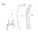
- Fig. 1 is shown an exemplary trained as a ship 1 vehicle.
- the ship 1 is here on a body of water 3 in a position 5 and moves at a speed v in the direction of travel 7 on a coast 9 to.
- ECA Emission Controlled Area 11
- a coastal area of the water body 3 is a so-called Emission Controlled Area 11 (ECA), which extends from the coast 9 over a defined distance up to a direction indicated by dashed line boundary 13.
- ECA Emission Controlled Area 11
- the ship 1 is still outside the ECA 11, but it is on its way to the ECA 11.
- In the coastal ECA 11 stricter emission regulations for the ship 1 than outside the ECA 11 on the water.
- Fig. 1 To the exhaust gas regulations in To comply with the ECA 11 and at the same time to ensure a cost - effective operation of the ship 1, has a Fig. 1 indicated by dashed lines drive means 15 of the ship 1 a control and / or control device 17 ( Fig. 2 ), by means of which the amount of pollutants of an exhaust gas (arrow 35, Fig. 2 ) of the drive device 15 can be adjusted according to the applicable local exhaust regulations accordingly.
- the drive device 15 of the ship 1 has an internal combustion engine 19, which is here coupled to a plurality of fuel tanks 21 and 23, here by way of example two.
- the fuel tank 21 in this case has a fuel with a high sulfur content, for example 1.5% to 3%, while the fuel tank 23 has a fuel with a low sulfur content, for example 15 ppm to 1000 ppm.
- a multi-way valve 25 is provided, to which both the fuel tank 23 and the internal combustion engine 19 are connected. In this case, the fuel flow from the fuel tank 21 to the internal combustion engine 19 is released in a first valve position of the multi-way valve 25, while the fuel flow from the fuel tank 23 to the internal combustion engine 19 is blocked. In a second valve position of the multi-way valve 25, the flow of fuel from the fuel tank 21 to the engine 19 is disabled while the fuel flow from the fuel tank 23 to the engine 19 is released.
- Fig. 2 further shows, the drive means 15 to an intake 27, by means of which the internal combustion engine 19 combustion air (arrow 29) is supplied.
- the intake manifold 27 is a continuously variable passage valve, here for example a throttle valve 31, arranged by means of which the supply of the combustion air 29 is controlled in the internal combustion engine 19.
- the drive device 15 optionally also has an exhaust gas recirculation 33, by means of which a part of an exhaust gas emitted by the internal combustion engine 19 can be returned to the intake tract 27.
- the exhaust gas is seen, seen in the exhaust gas flow direction, branched off downstream of the engine 19 and upstream of a bypass device 37 from an exhaust line 39 of the drive means 15 and seen in the air flow direction, downstream of the throttle valve 31 and upstream of the engine 19 in the intake 27 of the drive device 15 is initiated.
- two continuously variable passage valves 41 are provided here by way of example.
- One of the through valves 41 is, as seen in the exhaust gas flow direction downstream of the exhaust gas recirculation 33 and disposed upstream of the bypass device 37 in the exhaust line 39.
- the other one of the passage valves 41 is disposed in the exhaust gas recirculation 33.
- bypass device 37 at least part of the exhaust gas flow of the internal combustion engine 19 can be conducted past an exhaust aftertreatment system 43 of the drive device 15.
- One of the through valves 45 is, viewed in the exhaust gas flow direction, downstream of the bypass device 37 and disposed upstream of the exhaust aftertreatment system 43 in the exhaust line 39, while the other of the passage valves 45 is disposed in the bypass device 37.
- the exhaust aftertreatment system 43 here only by way of example, several components.
- the exhaust aftertreatment system 43 here, seen in the exhaust gas flow direction, arranged successively an oxidation catalyst 47, a particulate filter 49, a first SCR catalyst 51, a second SCR catalyst 53 and an ammonia barrier catalyst 55 on.
- the particle filter 49 can be regenerated in a defined adjustable frequency and over a defined adjustable time interval, for example, the particles stored in the particulate filter 49 are burned.
- a container 57 filled with a reducing agent is connected in each case.
- the reducing agent may be, for example, an aqueous urea solution.
- steplessly adjustable through valves 59 are provided here, for example.
- the already mentioned control and / or control device 17 of the drive means 15 a indicated by dashed lines location-determining system 61 by means of which the current position of the ship 1 can be determined.
- the determination of the current position can be done, for example, satellite-based using the GPS satellite system, the Galileo satellite system, the Glonass satellite system and / or the compass satellite system.
- the position of the ship 1 but also, for example, terrestrial via radio signal transmitting device, such as mobile masts or wireless LAN transmission devices are determined. From the means of the location-determining system 61 determined positions of the ship can then be determined by means of the control and / or control device 17 and the speed and the direction of travel of the ship 1.
- control and / or control device 17 here also has a transmitting and / or receiving device 63 shown with dashed lines, by means of the information on local exhaust regulations, here for example the exhaust gas regulations in the ECA 11 and the exhaust gas regulations outside the ECA 11 on the Waters 3, can be received by external information facilities, such as environmental or health authorities. The received information is then coupled to a data transmission with the transmitting and / or receiving device 63, in Fig. 2 also shown with dashed lines memory device 65 of the control and / or control device 17 is transmitted and stored there.
- a transmitting and / or receiving device 63 shown with dashed lines
- the regulating and / or control device 17 is also signal-technically coupled with the aforementioned valve devices 25, 41, 45 and 59 such that these valve devices can be controlled by means of the regulating and / or control device 17.
- the regulating and / or control device 17 is also signal-technically coupled to the particulate filter 49, so that the frequency and the duration of the regeneration of the particulate filter 49 can also be controlled by means of the regulating and / or control device 17.
- the control of said components by means of the control and / or control device 17 takes place by means of in Fig. 2 indicated with dashed lines control signals 67th
- control and / or control device 17 automatically or automatically determines the optimal time and appropriate measures, that is, a suitable control means the control signals 67, for the targeted adjustment and / or adjustment of the amount of pollutant in the emitted from the drive means 15 exhaust 35 and performs this action automatically or automatically.
Landscapes
- Engineering & Computer Science (AREA)
- Chemical & Material Sciences (AREA)
- Combustion & Propulsion (AREA)
- Mechanical Engineering (AREA)
- General Engineering & Computer Science (AREA)
- Chemical Kinetics & Catalysis (AREA)
- Toxicology (AREA)
- Health & Medical Sciences (AREA)
- Materials Engineering (AREA)
- Exhaust Gas After Treatment (AREA)
- Ocean & Marine Engineering (AREA)
- Environmental & Geological Engineering (AREA)
- General Health & Medical Sciences (AREA)
- Public Health (AREA)
- Processes For Solid Components From Exhaust (AREA)
- Exhaust-Gas Circulating Devices (AREA)
- Combined Controls Of Internal Combustion Engines (AREA)
Abstract
Description
- Die Erfindung betrifft ein Verfahren zum Betreiben eines Fahrzeugs, insbesondere eines Wasserfahrzeugs, nach dem Oberbegriff des Patentanspruches 1, eine Vorrichtung zum Betreiben eines Fahrzeugs, insbesondere eines Wasserfahrzeugs, nach dem Oberbegriff des Patentanspruches 8 sowie ein Fahrzeug, insbesondere ein Wasserfahrzeug, zur Durchführung des Verfahrens und/oder mit der Vorrichtung nach Patenanspruch 15.
- Wasserfahrzeuge, insbesondere Schiffe, überqueren regelmäßig Ländergrenzen und fahren so in Gebiete mit unterschiedlichen für die Wasserfahrzeuge geltenden Abgasvorschriften. Beispielsweise gibt es deutliche Unterschiede zwischen den auf dem offenen Meer zugelassenen Schadstoff-Emissionen und den zulässigen Schadstoff-Emissionen in küstennahen Gebieten Nordamerikas und Europas (sogenannte Emission Controlled Areas, kurz ECA). So darf beispielsweise in bestimmten ECAs aktuell nur ein Kraftstoff mit einem Schwefelgehalt von 15ppm bis 1000ppm verwendet werden, während auf dem offenen Meer ein Schwefelgehalt von 1.5% bis 3% zulässig ist. Fährt ein mit einer Brennkraftmaschine betriebenes Wasserfahrzeug in eine derartige ECA ein, wird daher üblicherweise die Kraftstoffart von hochschwefelhaltigem Kraftstoff auf niedrigschwefelhaltigem Kraftstoff umgeschaltet. Diese Umschaltung erfolgt zur Zeit manuell, das heißt durch aktiven Eingriff der Besatzung. Die manuelle Umschaltung hat jedoch zum einen eine hohe Fehlerrate aufgrund von Fehlbedienungen zur Folge. Zum anderen wird der Zeitpunkt der Umschaltung häufig nicht optimal gewählt, das heißt die Umschaltung erfolgt entweder zu früh oder zu spät. Während eine zu frühe Umschaltung beim Einfahren in eine ECA zu wirtschaftlichen Nachteilen für den Schiffsbetreiber führt, führt eine zu späte Umschaltung dazu, dass das Schiff mit zu hohen Schadstoff-Emissionen in die ECA einfährt.
- Aufgrund der immer strengeren Abgasvorschriften ist es zudem erforderlich, auch an Wasserfahrzeugen Abgasnachbehandlungssysteme vorzusehen.
- Aufgabe der Erfindung ist es, ein Verfahren und eine Vorrichtung zum Betreiben eines Fahrzeugs, insbesondere eines Wasserfahrzeugs, bereitzustellen, mittels denen die Schadstoffvorschriften auf einfache, kostengünstige und zuverlässige Weise eingehalten werden.
- Diese Aufgabe wird durch die Merkmale der unabhängigen Ansprüche gelöst. Bevorzugte Weiterbildungen sind in den Unteransprüchen offenbart.
- Die Erfindung betrifft ein Verfahren zum Betreiben eines Fahrzeugs, insbesondere eines Wasserfahrzeugs, wobei das Fahrzeug wenigstens eine, insbesondere in einem Abgas und/oder in einem Abwasser enthaltene, Schadstoffe emittierende Brennkraftmaschine aufweist, wobei mittels eines Standort-Bestimm-Systems die aktuelle Position des Fahrzeuges ermittelt wird, und wobei eine Regel- und/oder Steuereinrichtung vorgesehen ist, mittels der selbsttätig bzw. automatisch zumindest in Abhängigkeit von der ermittelten Position des Fahrzeugs und Informationen zu örtlichen Schadstoffvorschriften, insbesondere Abgas- und/oder Gewässervorschriften, die Menge wenigstens eines von der Brennkraftmaschine emittierten Schadstoffs gezielt eingestellt und/oder verstellt wird.
- Durch das erfindungsgemäße Verfahren wird die Einhaltung der Schadstoffvorschriften auf zuverlässige Weise sichergestellt, da die Menge des wenigstens einen Schadstoffs in Abhängigkeit von der Position des Fahrzeuges und den in dieser Position geltenden Schadstoffvorschriften automatisch mittels der Regel- und/oder Steuereinrichtung eingestellt und/oder verstellt wird. So kann beispielsweise eine hohe Fehlerrate bei der Einstellung bzw. Verstellung der emittierten Schadstoffmenge aufgrund von manuellen Fehlbedienungen vermieden werden. Das erfindungsgemäße Verfahren ist auch besonders kostengünstig, da die emittierte Schadstoffmenge automatisch nur dann an die üblicherweise höhere Kosten verursachenden, strengeren Schadstoffvorschriften angepasst werden, wenn dies auch erforderlich ist. Des Weiteren kann das erfindungsgemäße Verfahren auf besonders einfache Weise umgesetzt werden, da Fahrzeuge, insbesondere Wasserfahrzeuge, regelmäßig bereits ein Standort-Bestimm-System zur Ermittlung der aktuellen Position des Fahrzeuges aufweisen. Auch Systeme zur Einstellung bzw. Verstellung der emittierten Schadstoffmenge sind bereits regelmäßig an Fahrzeugen vorgesehen.
- Die Ermittlung der Position des Fahrzeuges kann dabei beispielsweise satellitengestützt, beispielsweise mittels des GPS-Satellitensystems, des Galileo-Satellitensystems, des Glonass-Satellitensystems oder des Compass-Satellitensystems erfolgen. Alternativ und/oder zusätzlich kann die Position des Fahrzeuges beispielsweise aber auch terrestrisch über Funksignal-Sendeeinrichtungen, insbesondere Mobilfunk-Sendeeinrichtungen oder W-LAN-Sendeeinrichtungen, ermittelt werden.
- In einer bevorzugten Verfahrensführung erfolgt die selbsttätige und/oder automatische Einstellung und/oder Verstellung der Schadstoff-Menge zusätzlich in Abhängig von der Ermittlung eines Geschwindigkeit-Bestimm-System ermittelten aktuellen Fahrzeug-Geschwindigkeit und der mittels eines Fahrtrichtung-Bestimm-Systems ermittelten aktuellen Fahrzeug-Fahrrichtung. Dadurch ist es, beispielswiese beim Einfahren in eine ECA, möglich, den optimalen Zeitpunkt zur gezielten Einstellung und/oder Verstellung der emittierten Schadstoffmenge zu bestimmen. So kann das Fahrzeug, beispielsweise beim Überschreiten einer ECA-Grenze, die jeweils geltenden Schadstoffvorschriften stets genau einhalten. Es werden daher die Einstellung und/oder Verstellung der emittierten Schadstoffmenge nicht zu früh und auch nicht zu spät durchgeführt. So können die geltenden Schadstoffvorschriften auf besonders kostengünstige und zuverlässige Weise eingehalten werden.
- Bevorzugt sind die Informationen zu den örtlichen Schadstoffvorschriften in der Regel- und/oder Steuereinrichtung abgespeichert, um die Informationen auf einfache und zuverlässige Weise bereitzustellen. Alternativ und/oder zusätzlich können die Informationen zu den örtlichen Schadstoffvorschriften von wenigstens einer externen Informations-Einrichtung an die Regel- und/oder Steuereinrichtung übermittelt werden. Die wenigstens eine externe Informations-Einrichtung kann dabei beispielsweise eine Umwelt- und/oder Gesundheitsbehörde sein, die beispielsweise über eine Funkverbindung datenübertragend mit der Regel- und/oder Steuereinrichtung verbunden werden kann. Durch die Übermittlung der Informationen zu den örtlichen Schadstoffvorschriften von den externen Information-Einrichtungen können auch Änderungen zu den örtlichen Schadstoffvorschriften deutlich besser berücksichtigt werden, so dass die automatische Einstellung und/oder Verstellung der emittierten Schadstoffmenge stets in Abhängigkeit von aktualisierten bzw. aktuell gültigen örtlichen Schadstoffvorschriften erfolgen kann. Sofern beispielsweise bei einer Inversionswetterlage strengere Schadstoffvorschriften in einer ECA gelten, werden diese dann automatisch von der Regel- und/oder Steuereinrichtung berücksichtigt. Bevorzugt kann zudem auch die aktuelle Schadstoffemission des Fahrzeugs von der Regel- und/oder Steuereinrichtung an eine externe Informations-Einrichtung übermittelt werden.
- Vorzugsweise kann zur gezielten Einstellung und/oder Verstellung der emittierten Schadstoffmenge mittels der Regel- und/oder Steuereinrichtung wenigstens eine die Schadstoff-Menge beeinflussende Komponente des Fahrzeuges in mehrere Betriebsmodi verstellt werden, wobei die emittierte Schadstoff-Menge des Fahrzeuges in jedem Betriebsmodus unterschiedlich ist. So kann die Schadstoff-Menge auf besonders einfache und zuverlässige Weise gezielt eingestellt und/oder verstellt werden.
- Bevorzugt wird zur Einstellung oder Verstellung der Schadstoff-Menge mittels der Regel- und/oder Steuereinrichtung wenigstens ein Parameter der Brennkraftmaschine verstellt und/oder eingestellt, um die emittierte Schadstoff-Menge einfach und effektiv zu verstellen und/oder einzustellen. Der wenigstens eine Parameter kann dabei beispielsweise das Verbrennungsluftverhältnis und/oder die Anzahl der Einspritzungen und/oder die mittels einer Abgasrückführung rückgeführte Abgasmenge und/oder der Einspritzdruck und/oder der Einspritzverlauf sein.
- Alternativ und/oder zusätzlich kann zur Einstellung und/oder Verstellung der Schadstoff-Menge mittels der Regel- und/oder Steuereinrichtung auch wenigstens ein Parameter eines Abgasnachbehandlungssystems des Fahrzeuges verstellt und/oder eingestellt werden. Auch dadurch kann die Schadstoff-Menge einfach und effektiv eingestellt und/oder verstellt werden. Der wenigstens eine Parameter des Abgasnachbehandlungssystems kann beispielsweise das Verbrennungsluftverhältnis und/oder die zugeführte Reduktionsmittel-Menge eines SCR-Katalysators des Abgasnachbehandlungssystems und/oder die Regeneration eines Partikelfilters des Abgasnachbehandlungssystems und/oder ein Abgasstrom durch eine Bypass-Einrichtung des Abgasnachbehandlungssystems sein. Zudem kann der wenigstens eine Parameter beispielsweise auch die durch einen Abgas-Wäscher geleitete Abwassermenge und/oder die vom als Wasserfahrzeug ausgebildeten Fahrzeug, insbesondere aus einem Abgas-Wäscher, ins Gewässer geleitete Abwassermenge und/oder der pM-Wert des vom als Wasserfahrzeug ausgebildeten Fahrzeug, insbesondere aus einem Abgas-Wäscher, ins Gewässer geleiteten Abwassers.
- Weiter alternativ und/oder zusätzlich kann zur Einstellung und/oder Verstellung der Schadstoff-Menge mittels der Regel- und/oder Steuereinrichtung auch die der Brennkraftmaschine zugeführte Kraftstoffart eingestellt und/oder verstellt werden.
- Zur Lösung der bereits genannten Aufgabenstellung wird ferner eine Vorrichtung zum Betreiben eines Fahrzeugs, insbesondere eines Wasserfahrzeugs vorgeschlagen, wobei das Fahrzeug wenigstens eine, insbesondere in einem Abgas und/oder in einem Abwasser enthaltene, Schadstoffe emittierende Brennkraftmaschine aufweist, wobei ein Standort-Bestimm-System vorgesehen ist, mittels dem die aktuelle Position des Fahrzeuges ermittelt werden kann, und wobei eine Regel- und/oder Steuereinrichtung vorgesehen ist, mittels der selbsttätig und/oder automatisch zumindest in Abhängigkeit von der ermittelten Position des Fahrzeugs und Informationen zu örtlichen Schadstoffvorschriften, insbesondere Abgas- und/oder Gewässervorschriften, die Menge wenigstens eines von der Brennkraftmaschine emittierten Schadstoffs gezielt eingestellt und/oder verstellt werden kann.
- Die sich durch die erfindungsgemäße Vorrichtung und die darauf rückbezogenen Unteransprüche ergebenen Vorteile sind identisch mit den bereits gewürdigten Vorteilen des erfindungsgemäßen Verfahrens, so dass diese an dieser Stelle nicht wiederholt werden.
- Ferner wird ein Fahrzeug, insbesondere ein Wasserfahrzeug, zur Durchführung des erfindungsgemäßen Verfahrens und/oder mit der erfindungsgemäßen Vorrichtung beansprucht. Die sich hieraus ergebenden Vorteile sind ebenfalls identisch mit den bereits gewürdigten Vorteilen des erfindungsgemäßen Verfahrens, so dass auch diese an dieser Stelle nicht wiederholt werden.
- Die vorstehenden erläuterten und/oder in den Unteransprüchen wiedergegebenen vorteilhaften Aus- und/oder Weiterbildungen der Erfindung können - außer zum Beispiel in den Fällen eindeutiger Abhängigkeiten oder unvereinbarer Alternativen - einzeln oder aber auch in beliebiger Kombination miteinander zur Anwendung kommen.
- Die Erfindung und ihre vorteilhaften Aus- und/oder Weiterbildungen sowie deren Vorteile werden nachfolgend anhand von Zeichnungen lediglich beispielhaft näher erläutert.
- Es zeigen:
-
Fig. 1 in einer schematischen Darstellung von oben ein auf einen Küstenbereich zufahrendes Schiff, und -
Fig. 2 in einer schematischen Darstellung ein Antriebssystem des Schiffs. - In
Fig. 1 ist ein beispielhaft als Schiff 1 ausgebildetes Fahrzeug gezeigt. Das Schiff 1 befindet sich hier auf einem Gewässer 3 in einer Position 5 und bewegt sich mit einer Geschwindigkeit v in Fahrrichtung 7 auf eine Küste 9 zu. In einem küstennahen Bereich des Gewässers 3 befindet sich eine sogenannte Emission Controlled Area 11 (ECA), die sich ausgehend von der Küste 9 über eine definierte Distanz bis hin zu einer mit gestrichelten Linie angedeuteten Begrenzung 13 erstreckt. Bei der inFig. 1 gezeigten Darstellung befindet sich das Schiff 1 noch außerhalb der ECA 11, es ist jedoch auf dem Weg in die ECA 11. In der küstennahen ECA 11 gelten strengere Abgasvorschriften für das Schiff 1 als außerhalb der ECA 11 auf dem Gewässer 3. Um die Abgasvorschriften in der ECA 11 einzuhalten und gleichzeitig auch einen kostengünstigen Betrieb des Schiffs 1 sicherzustellen, weist eine inFig. 1 mit gestrichelten Linien angedeutete Antriebseinrichtung 15 des Schiffs 1 eine Regel- und/oder Steuereinrichtung 17 (Fig. 2 ) auf, mittels der die Menge der Schadstoffe eines Abgases (Pfeil 35,Fig. 2 ) der Antriebseinrichtung 15 den geltenden örtlichen Abgasvorschriften entsprechend gezielt eingestellt werden können. - Der Aufbau und die Funktionsweise der Antriebseinrichtung 15 wird im Folgenden anhand der
Fig. 2 näher erläutert: - Wie in
Fig. 2 gezeigt ist, weist die Antriebseinrichtung 15 des Schiffs 1 eine Brennkraftmaschine 19 auf, die hier mit mehreren, hier beispielhaft zwei, Kraftstofftanks 21 und 23 gekoppelt ist. Der Kraftstofftank 21 weist dabei einen Kraftstoff mit einem hohen Schwefelgehalt, beispielsweise 1,5% bis 3%, auf, während der Kraftstofftank 23 einen Kraftstoff mit einem niedrigen Schwefelgehalt, beispielsweise 15ppm bis 1000ppm, aufweist. Zudem ist hier ein Mehrwege-Ventil 25 vorgesehen, an das sowohl die Kraftstofftanks 23 als auch die Brennkraftmaschine 19 angeschlossen sind. In einer ersten Ventilstellung des Mehrwege-Ventils 25 ist dabei der Kraftstoffstrom von dem Kraftstofftank 21 zu der Brennkraftmaschine 19 freigegeben, während der Kraftstoffstrom von dem Kraftstofftank 23 zu der Brennkraftmaschine 19 gesperrt ist. In einer zweiten Ventilstellung des Mehrwege-Ventils 25 ist der Kraftstoffstrom von dem Kraftstofftank 21 zu der Brennkraftmaschine 19 gesperrt, während der Kraftstoffstrom von dem Kraftstofftank 23 zu der Brennkraftmaschine 19 freigegeben ist. - Wie aus
Fig. 2 weiter hervorgeht, weist die Antriebseinrichtung 15 einen Ansaugtrakt 27 auf, mittels dem der Brennkraftmaschine 19 Verbrennungsluft (Pfeil 29) zugeführt wird. In dem Ansaugtrakt 27 ist ein stufenlos verstellbares Durchgangsventil, hier beispielhaft eine Drosselklappe 31, angeordnet, mittels der die Zufuhr der Verbrennungsluft 29 in die Brennkraftmaschine 19 gesteuert wird. Weiter weist die Antriebseinrichtung 15 optional auch eine Abgasrückführung 33 auf, mittels der ein Teil eines von der Brennkraftmaschine 19 emittierten Abgases in den Ansaugtrakt 27 rückgeführt werden kann. Das Abgas wird dabei, in Abgas-Strömungsrichtung gesehen, stromab der Brennkraftmaschine 19 und stromauf einer Bypass-Einrichtung 37 aus einem Abgasstrang 39 der Antriebseinrichtung 15 abgezweigt und, in Luft-Strömungsrichtung gesehen, stromab der Drosselklappe 31 und stromauf der Brennkraftmaschine 19 in den Ansaugtrakt 27 der Antriebseinrichtung 15 eingeleitet. Zur Einstellung der rückgeführten Abgasmenge sind hier beispielhaft zwei stufenlos verstellbare Durchgangsventile 41 vorgesehen. Eines der Durchgangsventile 41 ist dabei, in Abgas-Strömungsrichtung gesehen stromab der Abgasrückführung 33 und stromauf der Bypass-Einrichtung 37 in dem Abgasstrang 39 angeordnet. Das andere der Durchgangsventile 41 ist in der Abgasrückführung 33 angeordnet. - Des Weiteren kann mittels der Bypass-Einrichtung 37 zumindest ein Teil des Abgasstroms der Brennkraftmaschine 19 an einem Abgasnachbehandlungssystems 43 der Antriebseinrichtung 15 vorbeigeleitet werden. Die Einstellung der an dem Abgasnachbehandlungssystem 43 vorbeigeführten Abgasmenge erfolgt hier beispielhaft mittels zweier stufenlos verstellbarer Durchgangsventile 45. Eines der Durchgangsventile 45 ist dabei, in Abgas-Strömungsrichtung gesehen, stromab der Bypass-Einrichtung 37 und stromauf des Abgasnachbehandlungssystems 43 in dem Abgasstrang 39 angeordnet, während das andere der Durchgangsventile 45 in der Bypass-Einrichtung 37 angeordnet ist.
- Wie in
Fig. 2 weiter gezeigt ist, weist das Abgasnachbehandlungssystem 43, hier lediglich beispielhaft, mehrere Komponenten auf. So weist das Abgasnachbehandlungssystem 43 hier, in Abgas-Strömungsrichtung gesehen, nacheinander angeordnet einen Oxidationskatalysator 47, einen Partikelfilter 49, einen ersten SCR-Katalysator 51, einen zweiten SCR-Katalysator 53 und einen Ammoniak-Sperrkatalysator 55 auf. Der Partikelfilter 49 kann dabei in einer definiert einstellbaren Frequenz und über ein definiert einstellbares Zeitintervall regeneriert werden, wobei beispielsweise die in dem Partikelfilter 49 eingelagerten Partikel verbrannt werden. An die SCR-Katalysatoren 51 und 53 ist jeweils ein mit einem Reduktionsmittel befüllter Behälter 57 angeschlossen. Mittels des Reduktionsmittels können die SCR-Katalysatoren 51 und 53 die Stickoxide im Abgas 35 effektiv reduzieren. Das Reduktionsmittel kann dabei beispielsweise eine wässrige Harnstofflösung sein. Zur Einstellung der in die SCR-Katalysatoren 51 und 53 eingeleiteten Menge an Reduktionsmittel sind hier beispielweise stufenlos verstellbare Durchgangsventile 59 vorgesehen. - Weiter weist die bereits erwähnte Regel- und/oder Steuereinrichtung 17 der Antriebseinrichtung 15 ein mit gestrichelten Linien angedeutetes Standort-Bestimm-System 61 auf, mittels dem die aktuelle Position des Schiffs 1 ermittelt werden kann. Die Ermittlung der aktuellen Position kann dabei beispielsweise sattelitengestützt mit Hilfe des GPS-Satellitensystems, des Galileo-Satellitensystems, des Glonass-Satellitensystems und/oder des Kompass-Satellitensystems erfolgen. Ebenso kann die Position des Schiffs 1 aber beispielsweise auch terrestrisch über Funksignal-Sendeeinrichtung, beispielsweise Mobilfunkmasten oder W-LAN-Sendeeinrichtungen, ermittelt werden. Aus den mittels des Standort-Bestimm-Systems 61 ermittelten Positionen des Schiffs können dann mittels der Regel- und/oder Steuereinrichtung 17 auch die Geschwindigkeit und die Fahrrichtung des Schiffs 1 ermittelt werden.
- Zudem weist die Regel- und/oder Steuereinrichtung 17 hier auch eine mit gestrichelten Linien dargestellte Sende- und/oder Empfangseinrichtung 63 auf, mittels der Informationen zu örtlichen Abgasvorschriften, hier beispielhaft die Abgasvorschriften in der ECA 11 und die Abgasvorschriften außerhalb der ECA 11 auf dem Gewässer 3, von externen Informations-Einrichtungen, beispielsweise Umwelt- oder Gesundheitsbehörden, empfangen werden können. Die empfangenen Informationen werden dann an eine datenübertragend mit der Sende- und/oder Empfangseinrichtung 63 gekoppelte, in
Fig. 2 ebenfalls mit gestrichelten Linien dargestellte Speichereinrichtung 65 der Regel- und/oder Steuereinrichtung 17 übermittelt und dort abgespeichert. - Weiter ist die Regel- und/oder Steuereinrichtung 17 auch derart signaltechnisch mit den genannten Ventileinrichtungen 25, 41, 45 und 59 gekoppelt, dass diese Ventileinrichtungen mittels der Regel- und/oder Steuereinrichtung 17 gesteuert werden können. Ebenso ist die Regel- und/oder Steuereinrichtung 17 auch mit dem Partikelfilter 49 signaltechnisch gekoppelt, so dass mittels der Regel- und/oder Steuereinrichtung 17 auch die Frequenz und die Zeitdauer der Regeneration des Partikelfilters 49 gesteuert werden können. Die Steuerung der genannten Komponenten mittels der Regel- und/oder Steuereinrichtung 17 erfolgt dabei mittels in
Fig. 2 mit gestrichelten Linien angedeuteten Steuersignalen 67. - In Abhängigkeit von der Position, der Geschwindigkeit und der Fahrrichtung des Schiffs 1 und in Abhängigkeit von den Informationen zu den örtlichen Abgasvorschriften ermittelt die Regel- und/oder Steuereinrichtung 17 selbsttätig bzw. automatisch den optimalen Zeitpunkt und geeignete Maßnahmen, das heißt eine geeignete Steuerung mittels der Steuersignale 67, zur gezielten Einstellung und/oder Verstellung der Schadstoff-Menge in dem von der Antriebseinrichtung 15 emittierten Abgas 35 und führt diese Maßnahme selbsttätig bzw. automatisch aus.
-
- 1
- Schiff
- 3
- Gewässer
- 5
- Position
- 7
- Fahrrichtung
- 9
- Küste
- 11
- ECA
- 13
- Begrenzung
- 15
- Antriebseinrichtung
- 17
- Regel- und/oder Steuereinrichtung
- 19
- Brennkraftmaschine
- 21
- Kraftstofftank
- 23
- Kraftstofftank
- 25
- Mehrwege-Ventil
- 27
- Ansaugtrakt
- 29
- Verbrennungsluft
- 31
- Drosselklappe
- 33
- Abgasrückführung
- 35
- Abgas
- 37
- Bypass-Einrichtung
- 39
- Abgasstrang
- 41
- Durchgangsventil
- 43
- Abgasnachbehandlungssystem
- 45
- Durchgangsventil
- 47
- Oxidationskatalysator
- 49
- Partikelfilter
- 51
- SCR-Katalysator
- 53
- SCR-Katalysator
- 55
- Ammoniak-Sperrkatalysator
- 57
- Behälter
- 59
- Durchgangsventil
- 61
- Standort-Bestimm-System
- 63
- Sende- und/oder Empfangseinrichtung
- 65
- Speichereinrichtung
- 67
- Steuersignal
Claims (15)
- Verfahren zum Betreiben eines Fahrzeugs, insbesondere eines Wasserfahrzeugs, wobei das Fahrzeug (1) wenigstens eine, insbesondere in einem Abgas und/oder in einem Abwasser enthaltene, Schadstoffe (35) emittierende Brennkraftmaschine (19) aufweist, wobei mittels eines Standort-Bestimm-Systems (61) die aktuelle Position (5) des Fahrzeuges (1) ermittelt wird, und wobei eine Regel- und/oder Steuereinrichtung (17) vorgesehen ist, mittels der selbsttätig und/oder automatisch zumindest in Abhängigkeit von der ermittelten Position (5) des Fahrzeugs (1) und Informationen zu örtlichen Schadstoffvorschriften, insbesondere Abgas- und/oder Gewässervorschriften, die Menge wenigstens eines von der Brennkraftmaschine (19) emittierten Schadstoffs gezielt eingestellt und/oder verstellt wird.
- Verfahren nach Anspruch 1, dadurch gekennzeichnet, dass die selbsttätige und/oder automatische Einstellung und/oder Verstellung der Schadstoff-Menge zusätzlich in Abhängigkeit von der mittels eines Geschwindigkeit-Bestimm-Systems (17, 61) ermittelten aktuellen Fahrzeug-Geschwindigkeit (v) und der mittels eines Fahrrichtung-Bestimm-Systems (17, 61) ermittelten aktuellen Fahrzeug-Fahrrichtung (7) erfolgt.
- Verfahren nach Anspruch 1 oder 2, dadurch gekennzeichnet, dass die Informationen zu den örtlichen Schadstoffvorschriften in der Regel- und/oder Steuereinrichtung (17) abgespeichert sind, und/oder dass die Informationen zu den örtlichen Schadstoffvorschriften von wenigstens einer externen Informations-Einrichtung an die Regel- und/oder Steuereinrichtung (17) übermittelt werden, und/oder dass die aktuelle Schadstoffemission des Fahrzeugs von der Regel- und/oder Steuereinrichtung (17) an eine externe Informations-Einrichtung übermittelt wird.
- Verfahren nach einem der vorhergehenden Ansprüche, dadurch gekennzeichnet, dass zur gezielten Einstellung und/oder Verstellung der Schadstoff-Menge mittels der Regel- und/oder Steuereinrichtung (17) wenigstens eine, die Schadstoff-Menge der Brennkraftmaschine (19) beeinflussende Komponente des Fahrzeuges (1) in mehrere Betriebsmodi verstellt werden kann, wobei die emittierte Schadstoff-Menge der Brennkraftmaschine (19) in jedem Betriebsmodus unterschiedlich ist.
- Verfahren nach einem der vorhergehenden Ansprüche, dadurch gekennzeichnet, dass zur Einstellung und/oder Verstellung der Schadstoff-Menge mittels der Regel- und/oder Steuereinrichtung (17) wenigstens ein Parameter der Brennkraftmaschine (19) verstellt und/oder eingestellt wird, wobei bevorzugt vorgesehen ist, dass dieser Parameter das Verbrennungsluftverhältnis und/oder die Anzahl der Einspritzungen und/oder die mittels einer Abgasrückführung (33) rückgeführte Abgasmenge und/oder der Einspritzdruck und/oder der Einspritzverlauf ist.
- Verfahren nach einem der vorhergehenden Ansprüche, dadurch gekennzeichnet, dass zur Einstellung und/oder Verstellung der Schadstoff-Menge mittels der Regel- und/oder Steuereinrichtung (17) wenigstens ein Parameter eines Abgasnachbehandlungssystems (43) des Fahrzeugs (1) verstellt und/oder eingestellt wird, wobei bevorzugt vorgesehen ist, dass dieser Parameter das Verbrennungsluftverhältnis und/oder die zugeführte Reduktionsmittel-Menge eines SCR-Katalysators (51, 53) des Abgasnachbehandlungssystems (43) und/oder die Regeneration eines Partikelfilters (49) des Abgasnachbehandlungssystems (43) und/oder ein Abgasstrom durch eine Bypass-Einrichtung (37) des Abgasnachbehandlungssystems (43) und/oder die durch einen Abgas-Wäscher des Abgasnachbehandlungssystems (43) geleitete Abwassermenge und/oder die vom als Wasserfahrzeug ausgebildeten Fahrzeug, insbesondere aus einem Abgas-Wäscher, ins Gewässer geleitete Abwassermenge und/oder der pH-Wert des vom als Wasserfahrzeug ausgebildeten Fahrzeug, insbesondere aus einem Abgas-Wäscher, ins Gewässer geleiteten Abwassers ist.
- Verfahren nach einem der vorhergehenden Ansprüche, dadurch gekennzeichnet, dass zur Einstellung und/oder Verstellung der Schadstoff-Menge mittels der Regel- und/oder Steuereinrichtung (17) die der Brennkraftmaschine (19) zugeführte Kraftstoffart eingestellt und/oder verstellt wird.
- Vorrichtung zum Betreiben eines Fahrzeugs, insbesondere eines Wasserfahrzeugs und/oder zur Durchführung eines Verfahrens nach einem der vorhergehenden Ansprüche, wobei das Fahrzeug (1) wenigstens eine, insbesondere in einem Abgas und/oder in einem Abwasser enthaltene, Schadstoffe (35) emittierende Brennkraftmaschine (19) aufweist, wobei ein Standort-Bestimm-System (61) vorgesehen ist, mittels dem die aktuelle Position (5) des Fahrzeuges (1) ermittelbar ist, und wobei eine Regel- und/oder Steuereinrichtung (17) vorgesehen ist, mittels der selbsttätig und/oder automatisch zumindest in Abhängigkeit von der ermittelten Position (5) des Fahrzeugs (1) und Informationen zu örtlichen Schadstoffvorschriften, insbesondere Abgas- und/oder Gewässervorschriften, die Menge wenigstens eines von der Brennkraftmaschine (19) emittierten Schadsfoffs gezielt einstellbar und/oder verstellbar ist.
- Vorrichtung nach Anspruch 8, dadurch gekennzeichnet, dass ein Geschwindigkeit-Bestimm-System (17, 61) zur Ermittlung der Fahrzeug-Geschwindigkeit (v) und ein Fahrrichtung-Bestimm-System (17, 61) zur Ermittlung der Fahrzeug-Fahrrichtung (7) vorgesehen sind, und dass die Schadstoff-Menge zusätzlich in Abhängigkeit von der ermittelten aktuellen Fahrzeug-Geschwindigkeit (v) und der ermittelten aktuellen Fahrzeug-Fahrrichtung (7) mittels der Regel- und/oder Steuereinrichtung (17) einstellbar und/oder verstellbar ist.
- Vorrichtung nach Anspruch 8 oder 9, dadurch gekennzeichnet, dass die Regel- und/oder Steuereinrichtung (17) eine Speichereinrichtung (65) aufweist, in der die Informationen zu den örtlichen Schadstoffvorschriften abgespeichert sind, und/oder dass die Regel- und/oder Steuereinrichtung (17) eine Sende- und/oder Empfangseinrichtung (63) aufweist, mittels der die Informationen zu den örtlichen Schadstoffvorschriften von einer externen Informations-Einrichtung an die Regel- und/oder Steuereinrichtung (17) übermittelbar sind, und/oder mittels der die aktuelle Schadstoffemission des Fahrzeugs von der Regel- und/oder Steuereinrichtung (17) an eine externe Informations-Einrichtung übermittelt wird.
- Vorrichtung nach einem der Ansprüche 8 bis 10, dadurch gekennzeichnet, dass die Brennkraftmaschine (19) wenigstens eine in mehrere Stell-Positionen verlagerbare Stelleinrichtung (31) aufweist, durch deren Verlagerung wenigstens ein die Schadstoff-Menge beeinflussender Parameter der Brennkraftmaschine (19) verstellbar und/oder einstellbar ist, wobei die Verlagerung der Stelleinrichtung (31) mittels der Regel- und/oder Steuereinrichtung (17) regelbar und/oder steuerbar ist.
- Vorrichtung nach einem der Ansprüche 8 bis 11, dadurch gekennzeichnet, dass ein Abgasnachbehandlungssystem (43) des Fahrzeuges (1) wenigstens eine in mehrere Stell-Positionen verlagerbare Stelleinrichtung (41, 45, 59) aufweist, durch deren Verlagerung wenigstens ein die Schadstoff-Menge beeinflussender Parameter des Abgasnachbehandlungssystems (43) verstellbar und/oder einstellbar ist, wobei die Verlagerung der Stelleinrichtung (41, 45, 59) mittels der Regel- und/oder Steuereinrichtung (17) regelbar und/oder steuerbar ist.
- Vorrichtung nach Anspruch 12, dadurch gekennzeichnet, dass das Abgasnachbehandlungssystem (43) wenigstens eine Bypass-Einrichtung (37) aufweist, mittels der wenigstens ein Teil des Abgasstroms an wenigstens einem Abgasnachbehandlungselement (47, 49, 51, 53, 55), insbesondere an wenigstens einem SCR-Katalysator und/oder an wenigstens einer Entschwefelungs-Einrichtung, des Abgasnachbehandlungssystems (43) vorbeiführbar und/oder vorbeileitbar ist, und dass eine Ventileinrichtung (45) als Stelleinrichtung vorgesehen ist, mittels der der Abgasstrom durch die Bypass-Einrichtung (37) und durch das wenigstens eine Abgasnachbehandlungselement (47, 49, 51, 53, 55) verstellbar und/oder einstellbar ist.
- Vorrichtung nach einem der Ansprüche 8 bis 13, dadurch gekennzeichnet, dass eine in mehrere Stell-Positionen verlagerbare Stelleinrichtung (25) vorgesehen ist, durch deren Verlagerung die der Brennkraftmaschine (19) zugeführte Kraftstoffart verstellbar und/oder einstellbar ist, wobei die Verlagerung der Stelleinrichtung (25) mittels der Regel- und/oder Steuereinrichtung (17) regelbar und/oder steuerbar ist.
- Fahrzeug, insbesondere Wasserfahrzeug, zur Durchführung eines Verfahrens nach einem der Ansprüche 1 bis 7 und/oder mit einer Vorrichtung nach einem der Ansprüche 8 bis 14.
Applications Claiming Priority (1)
| Application Number | Priority Date | Filing Date | Title |
|---|---|---|---|
| DE102014017789.0A DE102014017789A1 (de) | 2014-12-03 | 2014-12-03 | Verfahren und Vorrichtung zum Betreiben eines Fahrzeugs, insbesondere eines Wasserfahrzeugs |
Publications (2)
| Publication Number | Publication Date |
|---|---|
| EP3032056A1 true EP3032056A1 (de) | 2016-06-15 |
| EP3032056B1 EP3032056B1 (de) | 2018-07-18 |
Family
ID=54359688
Family Applications (1)
| Application Number | Title | Priority Date | Filing Date |
|---|---|---|---|
| EP15003044.3A Active EP3032056B1 (de) | 2014-12-03 | 2015-10-24 | Verfahren und vorrichtung zum betreiben eines fahrzeugs, insbesondere eines wasserfahrzeugs |
Country Status (6)
| Country | Link |
|---|---|
| US (1) | US9840957B2 (de) |
| EP (1) | EP3032056B1 (de) |
| JP (1) | JP2016109134A (de) |
| KR (1) | KR102395934B1 (de) |
| CN (1) | CN105673163A (de) |
| DE (1) | DE102014017789A1 (de) |
Cited By (1)
| Publication number | Priority date | Publication date | Assignee | Title |
|---|---|---|---|---|
| EP4019112A4 (de) * | 2020-04-15 | 2022-11-16 | Fuji Electric Co., Ltd. | Abgasbehandlungsvorrichtung für ein schiff |
Families Citing this family (4)
| Publication number | Priority date | Publication date | Assignee | Title |
|---|---|---|---|---|
| JP7127796B2 (ja) * | 2018-03-26 | 2022-08-30 | 国立研究開発法人 海上・港湾・航空技術研究所 | 排ガス規制に対応した運転を行なう船舶、及び船舶の排ガス規制に対応した運転方法 |
| DE102018206350B4 (de) * | 2018-04-25 | 2021-01-07 | Ford Global Technologies, Llc | Verfahren zum Anpassen von Betriebsparametern einer Vorrichtung zur Abgasnachbehandlung |
| DE102018220715A1 (de) | 2018-11-30 | 2020-06-04 | Volkswagen Aktiengesellschaft | Abgasnachbehandlungssystem sowie Verfahren zur Abgasnachbehandlung eines Verbrennungsmotors |
| EP4463622A1 (de) * | 2022-04-01 | 2024-11-20 | Deutsches Zentrum für Luft- und Raumfahrt e.V. | Vorrichtung und verfahren zur steuerung einer verbrennungsantriebseinheit und einer oder mehreren damit verbundenen komponenten zur reinigung und/oder behandlung von deren abgasen |
Citations (5)
| Publication number | Priority date | Publication date | Assignee | Title |
|---|---|---|---|---|
| DE10143509A1 (de) * | 2001-09-05 | 2003-04-03 | Siemens Ag | Verfahren und Steuereinrichtung zur Steuerung einer Brennkraftmaschine |
| US20080178576A1 (en) * | 2006-11-28 | 2008-07-31 | Meier Diesel Filters, Inc. | Gps-activated exhaust filtration monitoring and control system |
| US20090171549A1 (en) * | 2007-12-31 | 2009-07-02 | Hyde Roderick A | Condition-sensitive exhaust control |
| EP2332826A1 (de) * | 2008-09-17 | 2011-06-15 | Yanmar Co., Ltd. | Abgasreinigungssystem für einen schiffsmotor |
| WO2014148256A1 (ja) * | 2013-03-18 | 2014-09-25 | ヤンマー株式会社 | 排気浄化システムおよびこれを備えた船舶 |
Family Cites Families (21)
| Publication number | Priority date | Publication date | Assignee | Title |
|---|---|---|---|---|
| JPH1136911A (ja) * | 1997-07-14 | 1999-02-09 | Unisia Jecs Corp | 燃料噴射量制御装置 |
| JP2001295631A (ja) * | 2000-04-12 | 2001-10-26 | Toyota Industries Corp | エンジンの排気浄化装置および排気浄化方法 |
| JP4486747B2 (ja) * | 2000-12-28 | 2010-06-23 | 株式会社堀場製作所 | 環境負荷制御システム |
| JP2004142537A (ja) * | 2002-10-23 | 2004-05-20 | Yamaha Marine Co Ltd | 船舶の操舵制御装置 |
| JP4779525B2 (ja) * | 2005-09-14 | 2011-09-28 | マツダ株式会社 | デュアルフューエルエンジンの燃料切換制御装置 |
| JP2009156046A (ja) * | 2007-12-25 | 2009-07-16 | Mitsubishi Fuso Truck & Bus Corp | エンジンの排気浄化装置 |
| JP2009221897A (ja) * | 2008-03-13 | 2009-10-01 | Fujitsu Ten Ltd | エンジン制御装置及びエンジン制御方法 |
| WO2009149603A1 (zh) * | 2008-06-13 | 2009-12-17 | Peng Sigan | 海船排烟脱硫方法及装置 |
| JP5330782B2 (ja) * | 2008-09-17 | 2013-10-30 | ヤンマー株式会社 | 船舶におけるエンジンの排気ガス浄化システム |
| JP2011106273A (ja) * | 2009-11-12 | 2011-06-02 | Mitsubishi Heavy Ind Ltd | 燃料噴射装置 |
| KR101303289B1 (ko) * | 2010-07-15 | 2013-09-03 | 주식회사 시뮬레이션테크 | 배기가스 오염물 저감시스템과 그 모니터링 방법 |
| EP2574393A1 (de) * | 2011-09-30 | 2013-04-03 | Alfa Laval Aalborg A/S | Wäschersystem und -verfahren |
| FI123737B (fi) * | 2012-02-13 | 2013-10-15 | Oy Langh Ship Ab | Menetelmä laivojen pakokaasuissa olevien epäpuhtauksien käsittelemiseksi, ja laiva, jossa pakokaasupesuri |
| JP5699099B2 (ja) * | 2012-02-28 | 2015-04-08 | 株式会社クボタ | 作業機 |
| JP5846042B2 (ja) * | 2012-05-16 | 2016-01-20 | 株式会社デンソー | リモートエンジン始動装置および車載機 |
| CN104736225B (zh) * | 2013-01-29 | 2018-05-04 | 富士电机株式会社 | 气体洗涤器的海水量控制装置、气体洗涤器的海水量控制方法、碱量控制装置及碱量控制方法 |
| ES2554112T5 (es) * | 2013-03-08 | 2023-05-22 | Alfa Laval Corp Ab | Sistema de limpieza y método para la reducción de SOx en gases de escape |
| JP5711315B2 (ja) * | 2013-07-26 | 2015-04-30 | ヤンマー株式会社 | 船舶におけるエンジンの排気ガス浄化システム |
| US20160129925A1 (en) * | 2014-11-10 | 2016-05-12 | Caterpillar Inc. | Fuel control strategy for locomotive consist |
| US9688296B2 (en) * | 2015-10-19 | 2017-06-27 | Electro-Motive Diesel, Inc. | Remote data backup for locomotive on-board equipment |
| US9828013B2 (en) * | 2015-11-09 | 2017-11-28 | Electro-Motive Diesel, Inc. | Train asset availability and reliability management system |
-
2014
- 2014-12-03 DE DE102014017789.0A patent/DE102014017789A1/de active Pending
-
2015
- 2015-10-24 EP EP15003044.3A patent/EP3032056B1/de active Active
- 2015-12-02 KR KR1020150170490A patent/KR102395934B1/ko active Active
- 2015-12-03 CN CN201510875938.2A patent/CN105673163A/zh active Pending
- 2015-12-03 JP JP2015236303A patent/JP2016109134A/ja active Pending
- 2015-12-03 US US14/957,806 patent/US9840957B2/en active Active
Patent Citations (5)
| Publication number | Priority date | Publication date | Assignee | Title |
|---|---|---|---|---|
| DE10143509A1 (de) * | 2001-09-05 | 2003-04-03 | Siemens Ag | Verfahren und Steuereinrichtung zur Steuerung einer Brennkraftmaschine |
| US20080178576A1 (en) * | 2006-11-28 | 2008-07-31 | Meier Diesel Filters, Inc. | Gps-activated exhaust filtration monitoring and control system |
| US20090171549A1 (en) * | 2007-12-31 | 2009-07-02 | Hyde Roderick A | Condition-sensitive exhaust control |
| EP2332826A1 (de) * | 2008-09-17 | 2011-06-15 | Yanmar Co., Ltd. | Abgasreinigungssystem für einen schiffsmotor |
| WO2014148256A1 (ja) * | 2013-03-18 | 2014-09-25 | ヤンマー株式会社 | 排気浄化システムおよびこれを備えた船舶 |
Cited By (1)
| Publication number | Priority date | Publication date | Assignee | Title |
|---|---|---|---|---|
| EP4019112A4 (de) * | 2020-04-15 | 2022-11-16 | Fuji Electric Co., Ltd. | Abgasbehandlungsvorrichtung für ein schiff |
Also Published As
| Publication number | Publication date |
|---|---|
| CN105673163A (zh) | 2016-06-15 |
| US9840957B2 (en) | 2017-12-12 |
| EP3032056B1 (de) | 2018-07-18 |
| JP2016109134A (ja) | 2016-06-20 |
| KR102395934B1 (ko) | 2022-05-10 |
| US20160160769A1 (en) | 2016-06-09 |
| DE102014017789A1 (de) | 2016-06-09 |
| KR20160067048A (ko) | 2016-06-13 |
Similar Documents
| Publication | Publication Date | Title |
|---|---|---|
| EP3032056B1 (de) | Verfahren und vorrichtung zum betreiben eines fahrzeugs, insbesondere eines wasserfahrzeugs | |
| DE19740702C1 (de) | Verfahren und Vorrichtung zum Betrieb einer mit Luftüberschuß arbeitenden Brennkraftmaschine | |
| DE102011006999B4 (de) | Verfahren und Motorsystem zum Abgasmischen | |
| EP3029289B1 (de) | Abgasnachbehandlungssystem für ein mit einer brennkraftmaschine betriebenes fahrzeug, insbesondere für ein wasserfahrzeug | |
| DE102012219306A1 (de) | Abgasbehandlungsverfahren und -systeme | |
| DE19926138A1 (de) | Verfahren und Vorrichtung zum Reinigen des Abgases einer Brennkraftmaschine, insbesondere einer Diesel-Brennkraftmaschine | |
| DE102015007646B4 (de) | Verfahren zum Betreiben einer Brennkraftmaschine und Steuerungseinrichtung zur Durchführung des Verfahrens | |
| DE102016222010B4 (de) | Verfahren zum Steuern einer Brennkraftmaschine mit einem Niederdruck-Abgasrückführungssystem | |
| DE102007039588A1 (de) | Vorrichtung und Verfahren zur Reinigung von Abgasen für eine Brennkraftmaschine | |
| DE102017217435A1 (de) | Abgassteuersystem für verbrennungsmotor | |
| DE102017218314B4 (de) | Verfahren zum Betreiben eines Dieselmotors und Dieselmotor mit Prüfung der NH3-Konzentration | |
| DE102018201869A1 (de) | Anordnung und Verfahren zur Behandlung eines von einem Verbrennungsmotor erzeugten Abgasstroms sowie Kraftfahrzeug | |
| DE102016209358B4 (de) | Verfahren, Vorrichtung zum Überwachen einer Stickoxidfalle, Computerprogramm und Computerprogrammprodukt | |
| DE102015219114A1 (de) | Verfahren und Vorrichtung zur Abgasnachbehandlung einer Brennkraftmaschine | |
| DE2747373B2 (de) | Verfahren und Vorrichtung zur Abgasentgiftung bei Verbrennungskraftmaschinen | |
| DE102018201870A1 (de) | Abgassystem zur Aufnahme eines von einem Verbrennungsmotor erzeugten Abgasstroms, Kraftfahrzeug und Verfahren zur Behandlung eines von einem Verbrennungsmotor erzeugten Abgasstroms | |
| DE10001310A1 (de) | Vorrichtung und Verfahren zur Steuerung einer NOx-Regeneration eines NOx-Speicherkatalysators | |
| DE102018003131B4 (de) | Verfahren, Vorrichtung und System zur Verringerung des Schadstoffausstoßes eines Kraftfahrzeugs | |
| DE102015202904B4 (de) | Betriebsverfahren und Kraftfahrzeug | |
| DE102018201868A1 (de) | Abgassystem, Kraftfahrzeug und Verfahren zur Abgasbehandlung | |
| DE102016210188A1 (de) | Verfahren und Vorrichtung zur Abgasnachbehandlung | |
| DE10038458A1 (de) | Vorrichtung und Verfahren zur Abgasreinigung | |
| DE102008045594A1 (de) | Verfahren und Vorrichtung zur Zudosierung eines Reduktionsmittels in einen Abgasstrang einer Brennkraftmaschine eines Fahrzeuges | |
| DE102018203495A1 (de) | Anordnung mit einem Dual-LNT-Katalysator und deren Verwendung, Kraftfahrzeug sowie Verfahren zur Behandlung eines Abgasstroms | |
| DE102018200452B4 (de) | Entschwefelung einzelner Stickoxidspeicherkatalysatoren in einem dualen Stickoxidspeicherkatalysator-System |
Legal Events
| Date | Code | Title | Description |
|---|---|---|---|
| PUAI | Public reference made under article 153(3) epc to a published international application that has entered the european phase |
Free format text: ORIGINAL CODE: 0009012 |
|
| AK | Designated contracting states |
Kind code of ref document: A1 Designated state(s): AL AT BE BG CH CY CZ DE DK EE ES FI FR GB GR HR HU IE IS IT LI LT LU LV MC MK MT NL NO PL PT RO RS SE SI SK SM TR |
|
| AX | Request for extension of the european patent |
Extension state: BA ME |
|
| 17P | Request for examination filed |
Effective date: 20161215 |
|
| 17Q | First examination report despatched |
Effective date: 20170412 |
|
| RIC1 | Information provided on ipc code assigned before grant |
Ipc: F02D 41/00 20060101ALI20171115BHEP Ipc: F01N 13/00 20100101ALI20171115BHEP Ipc: F02D 41/02 20060101ALI20171115BHEP Ipc: F01N 3/031 20060101ALI20171115BHEP Ipc: F01N 3/10 20060101AFI20171115BHEP Ipc: F02D 41/38 20060101ALI20171115BHEP Ipc: F01N 3/025 20060101ALI20171115BHEP Ipc: F01N 3/20 20060101ALI20171115BHEP Ipc: F02D 41/40 20060101ALI20171115BHEP Ipc: F01N 9/00 20060101ALI20171115BHEP |
|
| GRAP | Despatch of communication of intention to grant a patent |
Free format text: ORIGINAL CODE: EPIDOSNIGR1 |
|
| INTG | Intention to grant announced |
Effective date: 20180212 |
|
| GRAS | Grant fee paid |
Free format text: ORIGINAL CODE: EPIDOSNIGR3 |
|
| GRAA | (expected) grant |
Free format text: ORIGINAL CODE: 0009210 |
|
| AK | Designated contracting states |
Kind code of ref document: B1 Designated state(s): AL AT BE BG CH CY CZ DE DK EE ES FI FR GB GR HR HU IE IS IT LI LT LU LV MC MK MT NL NO PL PT RO RS SE SI SK SM TR |
|
| REG | Reference to a national code |
Ref country code: GB Ref legal event code: FG4D Free format text: NOT ENGLISH |
|
| REG | Reference to a national code |
Ref country code: CH Ref legal event code: EP Ref country code: CH Ref legal event code: NV Representative=s name: WEINMANN ZIMMERLI, CH |
|
| REG | Reference to a national code |
Ref country code: IE Ref legal event code: FG4D Free format text: LANGUAGE OF EP DOCUMENT: GERMAN |
|
| REG | Reference to a national code |
Ref country code: AT Ref legal event code: REF Ref document number: 1019614 Country of ref document: AT Kind code of ref document: T Effective date: 20180815 |
|
| REG | Reference to a national code |
Ref country code: DE Ref legal event code: R096 Ref document number: 502015005081 Country of ref document: DE |
|
| REG | Reference to a national code |
Ref country code: NL Ref legal event code: FP |
|
| REG | Reference to a national code |
Ref country code: FR Ref legal event code: PLFP Year of fee payment: 4 |
|
| REG | Reference to a national code |
Ref country code: SE Ref legal event code: TRGR |
|
| REG | Reference to a national code |
Ref country code: LT Ref legal event code: MG4D |
|
| PG25 | Lapsed in a contracting state [announced via postgrant information from national office to epo] |
Ref country code: GR Free format text: LAPSE BECAUSE OF FAILURE TO SUBMIT A TRANSLATION OF THE DESCRIPTION OR TO PAY THE FEE WITHIN THE PRESCRIBED TIME-LIMIT Effective date: 20181019 Ref country code: PL Free format text: LAPSE BECAUSE OF FAILURE TO SUBMIT A TRANSLATION OF THE DESCRIPTION OR TO PAY THE FEE WITHIN THE PRESCRIBED TIME-LIMIT Effective date: 20180718 Ref country code: RS Free format text: LAPSE BECAUSE OF FAILURE TO SUBMIT A TRANSLATION OF THE DESCRIPTION OR TO PAY THE FEE WITHIN THE PRESCRIBED TIME-LIMIT Effective date: 20180718 Ref country code: LT Free format text: LAPSE BECAUSE OF FAILURE TO SUBMIT A TRANSLATION OF THE DESCRIPTION OR TO PAY THE FEE WITHIN THE PRESCRIBED TIME-LIMIT Effective date: 20180718 Ref country code: BG Free format text: LAPSE BECAUSE OF FAILURE TO SUBMIT A TRANSLATION OF THE DESCRIPTION OR TO PAY THE FEE WITHIN THE PRESCRIBED TIME-LIMIT Effective date: 20181018 Ref country code: NO Free format text: LAPSE BECAUSE OF FAILURE TO SUBMIT A TRANSLATION OF THE DESCRIPTION OR TO PAY THE FEE WITHIN THE PRESCRIBED TIME-LIMIT Effective date: 20181018 Ref country code: IS Free format text: LAPSE BECAUSE OF FAILURE TO SUBMIT A TRANSLATION OF THE DESCRIPTION OR TO PAY THE FEE WITHIN THE PRESCRIBED TIME-LIMIT Effective date: 20181118 |
|
| PG25 | Lapsed in a contracting state [announced via postgrant information from national office to epo] |
Ref country code: AL Free format text: LAPSE BECAUSE OF FAILURE TO SUBMIT A TRANSLATION OF THE DESCRIPTION OR TO PAY THE FEE WITHIN THE PRESCRIBED TIME-LIMIT Effective date: 20180718 Ref country code: HR Free format text: LAPSE BECAUSE OF FAILURE TO SUBMIT A TRANSLATION OF THE DESCRIPTION OR TO PAY THE FEE WITHIN THE PRESCRIBED TIME-LIMIT Effective date: 20180718 Ref country code: LV Free format text: LAPSE BECAUSE OF FAILURE TO SUBMIT A TRANSLATION OF THE DESCRIPTION OR TO PAY THE FEE WITHIN THE PRESCRIBED TIME-LIMIT Effective date: 20180718 |
|
| REG | Reference to a national code |
Ref country code: DE Ref legal event code: R097 Ref document number: 502015005081 Country of ref document: DE |
|
| PG25 | Lapsed in a contracting state [announced via postgrant information from national office to epo] |
Ref country code: EE Free format text: LAPSE BECAUSE OF FAILURE TO SUBMIT A TRANSLATION OF THE DESCRIPTION OR TO PAY THE FEE WITHIN THE PRESCRIBED TIME-LIMIT Effective date: 20180718 Ref country code: ES Free format text: LAPSE BECAUSE OF FAILURE TO SUBMIT A TRANSLATION OF THE DESCRIPTION OR TO PAY THE FEE WITHIN THE PRESCRIBED TIME-LIMIT Effective date: 20180718 Ref country code: RO Free format text: LAPSE BECAUSE OF FAILURE TO SUBMIT A TRANSLATION OF THE DESCRIPTION OR TO PAY THE FEE WITHIN THE PRESCRIBED TIME-LIMIT Effective date: 20180718 Ref country code: CZ Free format text: LAPSE BECAUSE OF FAILURE TO SUBMIT A TRANSLATION OF THE DESCRIPTION OR TO PAY THE FEE WITHIN THE PRESCRIBED TIME-LIMIT Effective date: 20180718 |
|
| PLBE | No opposition filed within time limit |
Free format text: ORIGINAL CODE: 0009261 |
|
| STAA | Information on the status of an ep patent application or granted ep patent |
Free format text: STATUS: NO OPPOSITION FILED WITHIN TIME LIMIT |
|
| PG25 | Lapsed in a contracting state [announced via postgrant information from national office to epo] |
Ref country code: SK Free format text: LAPSE BECAUSE OF FAILURE TO SUBMIT A TRANSLATION OF THE DESCRIPTION OR TO PAY THE FEE WITHIN THE PRESCRIBED TIME-LIMIT Effective date: 20180718 Ref country code: DK Free format text: LAPSE BECAUSE OF FAILURE TO SUBMIT A TRANSLATION OF THE DESCRIPTION OR TO PAY THE FEE WITHIN THE PRESCRIBED TIME-LIMIT Effective date: 20180718 Ref country code: SM Free format text: LAPSE BECAUSE OF FAILURE TO SUBMIT A TRANSLATION OF THE DESCRIPTION OR TO PAY THE FEE WITHIN THE PRESCRIBED TIME-LIMIT Effective date: 20180718 |
|
| 26N | No opposition filed |
Effective date: 20190423 |
|
| REG | Reference to a national code |
Ref country code: BE Ref legal event code: MM Effective date: 20181031 |
|
| PG25 | Lapsed in a contracting state [announced via postgrant information from national office to epo] |
Ref country code: MC Free format text: LAPSE BECAUSE OF FAILURE TO SUBMIT A TRANSLATION OF THE DESCRIPTION OR TO PAY THE FEE WITHIN THE PRESCRIBED TIME-LIMIT Effective date: 20180718 Ref country code: LU Free format text: LAPSE BECAUSE OF NON-PAYMENT OF DUE FEES Effective date: 20181024 |
|
| REG | Reference to a national code |
Ref country code: IE Ref legal event code: MM4A |
|
| PG25 | Lapsed in a contracting state [announced via postgrant information from national office to epo] |
Ref country code: SI Free format text: LAPSE BECAUSE OF FAILURE TO SUBMIT A TRANSLATION OF THE DESCRIPTION OR TO PAY THE FEE WITHIN THE PRESCRIBED TIME-LIMIT Effective date: 20180718 Ref country code: BE Free format text: LAPSE BECAUSE OF NON-PAYMENT OF DUE FEES Effective date: 20181031 |
|
| REG | Reference to a national code |
Ref country code: DE Ref legal event code: R081 Ref document number: 502015005081 Country of ref document: DE Owner name: MAN TRUCK & BUS SE, DE Free format text: FORMER OWNER: MAN TRUCK & BUS AG, 80995 MUENCHEN, DE |
|
| PG25 | Lapsed in a contracting state [announced via postgrant information from national office to epo] |
Ref country code: IE Free format text: LAPSE BECAUSE OF NON-PAYMENT OF DUE FEES Effective date: 20181024 |
|
| PG25 | Lapsed in a contracting state [announced via postgrant information from national office to epo] |
Ref country code: MT Free format text: LAPSE BECAUSE OF FAILURE TO SUBMIT A TRANSLATION OF THE DESCRIPTION OR TO PAY THE FEE WITHIN THE PRESCRIBED TIME-LIMIT Effective date: 20180718 |
|
| PG25 | Lapsed in a contracting state [announced via postgrant information from national office to epo] |
Ref country code: TR Free format text: LAPSE BECAUSE OF FAILURE TO SUBMIT A TRANSLATION OF THE DESCRIPTION OR TO PAY THE FEE WITHIN THE PRESCRIBED TIME-LIMIT Effective date: 20180718 |
|
| PG25 | Lapsed in a contracting state [announced via postgrant information from national office to epo] |
Ref country code: PT Free format text: LAPSE BECAUSE OF FAILURE TO SUBMIT A TRANSLATION OF THE DESCRIPTION OR TO PAY THE FEE WITHIN THE PRESCRIBED TIME-LIMIT Effective date: 20180718 |
|
| PG25 | Lapsed in a contracting state [announced via postgrant information from national office to epo] |
Ref country code: HU Free format text: LAPSE BECAUSE OF FAILURE TO SUBMIT A TRANSLATION OF THE DESCRIPTION OR TO PAY THE FEE WITHIN THE PRESCRIBED TIME-LIMIT; INVALID AB INITIO Effective date: 20151024 Ref country code: CY Free format text: LAPSE BECAUSE OF FAILURE TO SUBMIT A TRANSLATION OF THE DESCRIPTION OR TO PAY THE FEE WITHIN THE PRESCRIBED TIME-LIMIT Effective date: 20180718 Ref country code: MK Free format text: LAPSE BECAUSE OF NON-PAYMENT OF DUE FEES Effective date: 20180718 |
|
| GBPC | Gb: european patent ceased through non-payment of renewal fee |
Effective date: 20191024 |
|
| PG25 | Lapsed in a contracting state [announced via postgrant information from national office to epo] |
Ref country code: GB Free format text: LAPSE BECAUSE OF NON-PAYMENT OF DUE FEES Effective date: 20191024 |
|
| REG | Reference to a national code |
Ref country code: AT Ref legal event code: MM01 Ref document number: 1019614 Country of ref document: AT Kind code of ref document: T Effective date: 20201024 |
|
| PG25 | Lapsed in a contracting state [announced via postgrant information from national office to epo] |
Ref country code: AT Free format text: LAPSE BECAUSE OF NON-PAYMENT OF DUE FEES Effective date: 20201024 |
|
| REG | Reference to a national code |
Ref country code: CH Ref legal event code: U11 Free format text: ST27 STATUS EVENT CODE: U-0-0-U10-U11 (AS PROVIDED BY THE NATIONAL OFFICE) Effective date: 20251101 |
|
| PGFP | Annual fee paid to national office [announced via postgrant information from national office to epo] |
Ref country code: NL Payment date: 20251024 Year of fee payment: 11 |
|
| PGFP | Annual fee paid to national office [announced via postgrant information from national office to epo] |
Ref country code: DE Payment date: 20251028 Year of fee payment: 11 |
|
| PGFP | Annual fee paid to national office [announced via postgrant information from national office to epo] |
Ref country code: FI Payment date: 20251024 Year of fee payment: 11 Ref country code: IT Payment date: 20251022 Year of fee payment: 11 |
|
| PGFP | Annual fee paid to national office [announced via postgrant information from national office to epo] |
Ref country code: FR Payment date: 20251027 Year of fee payment: 11 |
|
| PGFP | Annual fee paid to national office [announced via postgrant information from national office to epo] |
Ref country code: CH Payment date: 20251101 Year of fee payment: 11 Ref country code: SE Payment date: 20251024 Year of fee payment: 11 |