EP3032055B1 - Oil jet - Google Patents
Oil jet Download PDFInfo
- Publication number
- EP3032055B1 EP3032055B1 EP14835261.0A EP14835261A EP3032055B1 EP 3032055 B1 EP3032055 B1 EP 3032055B1 EP 14835261 A EP14835261 A EP 14835261A EP 3032055 B1 EP3032055 B1 EP 3032055B1
- Authority
- EP
- European Patent Office
- Prior art keywords
- oil
- cylinder
- pressure
- piston
- valve
- Prior art date
- Legal status (The legal status is an assumption and is not a legal conclusion. Google has not performed a legal analysis and makes no representation as to the accuracy of the status listed.)
- Not-in-force
Links
Images

Classifications
-
- F—MECHANICAL ENGINEERING; LIGHTING; HEATING; WEAPONS; BLASTING
- F01—MACHINES OR ENGINES IN GENERAL; ENGINE PLANTS IN GENERAL; STEAM ENGINES
- F01P—COOLING OF MACHINES OR ENGINES IN GENERAL; COOLING OF INTERNAL-COMBUSTION ENGINES
- F01P3/00—Liquid cooling
- F01P3/06—Arrangements for cooling pistons
- F01P3/08—Cooling of piston exterior only, e.g. by jets
-
- F—MECHANICAL ENGINEERING; LIGHTING; HEATING; WEAPONS; BLASTING
- F01—MACHINES OR ENGINES IN GENERAL; ENGINE PLANTS IN GENERAL; STEAM ENGINES
- F01M—LUBRICATING OF MACHINES OR ENGINES IN GENERAL; LUBRICATING INTERNAL COMBUSTION ENGINES; CRANKCASE VENTILATING
- F01M1/00—Pressure lubrication
- F01M1/08—Lubricating systems characterised by the provision therein of lubricant jetting means
- F01M2001/083—Lubricating systems characterised by the provision therein of lubricant jetting means for lubricating cylinders
Definitions
- the present invention relates to an oil jet that is used for cooling a piston of an internal combustion engine.
- An oil jet is an apparatus which injects oil that is supplied from the oil passage, to a piston or a gap between the piston and a cylinder bore, and which thereby cools the piston that is in a high temperature state.
- a conventional oil jet generally used has a mechanism for opening and closing its valve in accordance with oil pressure. Specifically, a body of the valve is biased in a direction acting against the oil pressure by a spring, and the valve is configured to open as a result of the body of the valve separating from a valve seat when a force of oil pressure acting on the body of the valve exceeds the force of the spring.
- the oil pressure increases with an increase in engine speed, whereas because the temperature of the piston increases with an increase in the engine speed, the above described mechanism can cool the piston by injecting oil in a situation in which the temperature of the piston becomes high and prevent the piston from being excessively cooled by stopping the injection of oil in a situation in which the temperature of the piston is not high.
- An oil jet disclosed in the following Patent Literature 1 also has a mechanism for opening and closing its valve in accordance with oil pressure.
- This oil jet has a further mechanism for changing the injection amount of oil in accordance with oil temperature.
- the mechanism corresponds to a throttle member that is disposed upstream of the valve.
- a plurality of throttle holes are formed in the throttle member. Fluid resistance of oil acts when passing through these throttle holes, and the magnitude thereof increases with an increase in the viscosity of the oil. Because of this, the flow rate of the oil passing through the throttle holes becomes smaller when the temperature of the oil is low and the viscosity of the oil is high, whereas the flow rate of the oil passing through the throttle holes becomes larger when the temperature of the oil is high and the viscosity of the oil is low.
- the injection amount of oil is suppressed because of low oil temperature if it is during the cold condition immediately after an engine start up, whereas the injection amount of oil is increased in association with an increase in oil temperature if it is after completion of a warm up.
- An oil jet which has a mechanism for opening and closing its valve in accordance with oil temperature as well as a mechanism for opening and closing the valve in accordance with oil pressure.
- An oil jet disclosed in the following Patent Literature 2 has a first mechanism for opening and closing its valve with a normal spring and a second mechanism for opening and closing its valve with a spring made of a shape-memory alloy.
- the first mechanism having the normal spring the valve is opened when a force of oil pressure acting on a body of the valve exceeds the force of the spring.
- the second mechanism having the spring made of a shape-memory alloy, the valve becomes closed during the cold condition in which the spring is compressed, whereas the valve becomes opened during the warm condition in which the spring is restored to expand. With such mechanisms, both valves are opened to inject oil only when the oil pressure is high and the oil temperature is high.
- an oil jet as with, for example, an oil jet disclosed in the following Patent Literature 3, is proposed which can electrically control the execution and stopping of oil injection by driving a body of its valve using a solenoid.
- Patent Literature 3 discloses an oil jet which can electrically control the execution and stopping of oil injection by driving a body of its valve using a solenoid.
- Each of the oil jets disclosed in Patent Literature 1 and 2 is configured such that the operational state is changed depending on oil temperature as well as oil pressure.
- the oil temperature is closely related to the temperature state of the piston as well as the oil pressure, and therefore, according to the configuration in which the operational state of the oil jet is changed also depending on the oil temperature, it is conceivable that the piston could be cooled more properly with the injection of oil, compared with a general oil jet by which its valve is opened and closed simply in accordance with the oil pressure.
- Patent Literature 1 Since the oil jet disclosed in Patent Literature 1 includes the throttle member disposed in a flow passage of oil, pressure loss is produced when oil passes through the throttle member. Although the pressure loss produced becomes smaller if the viscosity of oil decreases as a result of an increase in the oil temperature, the pressure loss is larger than that of an oil jet which does not include the throttle member. The amount of oil injected to the piston at the time of high temperature is decreased by an amount corresponding to the pressure loss. Further, since the injection amount of oil is suppressed until the oil temperature is sufficiently increased even if the oil pressure rises, there is a concern that in a case like when the internal combustion engine during the cold condition is operated at high engine speed, a sufficient amount of oil may not be injected even though the temperature of the piston is high.
- the problem described so far can be solved by changing, in accordance with the oil temperature, a valve opening pressure when a valve is opened. That is to say, a problem that each of the oil jets disclosed in Patent Literature 1 and 2 has would not occur, if the valve opening pressure could increase when the oil temperature is low, and if the valve opening pressure could decrease with an increase in the oil temperature.
- the valve opening pressure be self-regulated mechanically instead of electrically operating the opening and closing of the valve as in the oil jet disclosed in Patent Literature 3. This is because it has an advantage in terms of reliability and cost.
- valve opening pressure can be self-regulated mechanically and smoothly in accordance with the oil temperature and that injection of oil by an oil injection nozzle can be stably performed
- a configuration be adopted such that the oil that is supplied inside the oil jet can be effectively utilized.
- the present invention has been conceived in view of the above described problem, and an object of the present invention is to provide an oil jet in which a valve opening pressure is self-regulated mechanically in accordance with oil temperature and in which the oil that is supplied is effectively utilized.
- An oil jet according to the present invention includes at least a body, a piston valve, a spring, a first oil injection nozzle and a second oil injection nozzle.
- the body is a main body part of the oil jet attached to a cylinder block of an internal combustion engine, and has an oil supply port, a cylinder and an oil injection port.
- the oil supply port is formed so as to open into an oil passage in the cylinder block in a state in which the body is attached to the cylinder block.
- One end of the cylinder is communicated with the oil supply port, and another end thereof is closed.
- the oil injection port opens on a side surface of the cylinder.
- the piston valve is accommodated in the cylinder and forms a closed compartment in the cylinder.
- an orifice which makes the closed compartment being communicated with a side of the oil supply port is formed.
- the spring biases the piston valve toward a position at which the oil injection port is closed.
- the first oil injection nozzle is connected to the oil injection port and is for fixing a direction of injection of oil.
- a leak hole which allows oil to be leaked outside of the cylinder from the closed compartment is open at the side surface of the cylinder.
- the oil jet according to the present invention includes the second oil injection nozzle that is connected to the leak hole and that is for fixing a direction of injection of oil.
- the oil injection port is opened and closed by the piston valve.
- the pressure of oil flowing through the oil passage in the cylinder block acts, and at the same time, the pressure of oil in the closed compartment and a biasing force by the spring act in a direction opposite to this.
- the piston valve is pushed by the oil supplied from the oil passage to move from a position which covers the oil injection port. This allows the piston valve to be in the opened state so that the oil injection port is communicated with the oil supply port, and allows oil to be supplied to the oil injection port so that oil injection from the first oil injection nozzle is achieved.
- the oil pressure in the closed compartment varies in accordance with a relation between the flow rate of oil flowing into the closed compartment through the orifice and the flow rate of oil leaking from the closed compartment through the leak hole.
- oil density determines the flow rate. More specifically, the flow rate of the oil passing through the orifice to flow into the closed compartment from the oil injection port side is inversely proportional to the one-second power of the oil density.
- oil viscosity determines the flow rate. More specifically, the flow rate of the oil passing through the leak hole to leak outside the body from the closed compartment in the cylinder is inversely proportional to the oil viscosity.
- an important thing is that there is a large difference in the sensitivities thereof with respect to the oil temperature between the oil density and the oil viscosity.
- the oil density changes little with respect to a change in the oil temperature, and the oil density can be recognized as being nearly constant in a normal temperature range of oil in an internal combustion engine. In contrast to this, the oil viscosity changes quite greatly with respect to a change in the oil temperature.
- the oil viscosity during the cold time is more than ten times the oil viscosity after warm up. Because of this, when compared at the same pressure in the closed compartment, although the flow rate of the oil which flows into the closed compartment from the orifice does not change greatly depending on the oil temperature, the flow rate of the oil which is leaked from the leak hole increases with an increase in the oil temperature. As the flow rate of the oil which is leaked from the leak hole becomes larger, the oil pressure in the closed compartment becomes lower.
- a valve opening pressure is determined depending on the oil pressure in the closed compartment.
- the valve opening pressure is self-regulated mechanically so that the valve opening pressure becomes lower with an increase in the oil temperature and the valve opening pressure becomes higher with a decrease in the oil temperature.
- the other end of the cylinder that is closed may be positioned at a lower side in a direction of gravitational force in the cylinder.
- a distal end of the first oil injection nozzle may be directed to a back side of a piston that reciprocates in a cylinder of the internal combustion engine, and a distal end of the second oil injection nozzle may be directed to a cylinder bore of the internal combustion engine.
- the oil jet according to the present invention can self-regulate a valve opening pressure mechanically in accordance with oil temperature and in which the oil that is supplied is effectively utilized.
- an oil jet 100 includes a body 2 attached to a cylinder block 40 of an internal combustion engine.
- the attachment of the body 2 to the cylinder block 40 can be made, for example, via a plate (not shown in the drawings).
- an oil passage 42 through which oil pressurized by an oil pump (not shown in the drawings) flows is formed. Since the oil pump is driven by a power received from a crankshaft of the internal combustion engine, the oil pressure inside the oil passage 42 is low when the engine speed is low, and the oil pressure inside the oil passage 42 increases with an increase in the engine speed.
- an oil supply port 6 which opens into this oil passage 42 is formed.
- a cylinder 4 an inlet of which is the oil supply port 6 is formed.
- the cylinder 4 is formed so as to penetrate the body 2, the outlet thereof is covered by a plug 8. More specifically, the plug 8 constitutes the bottom portion of the cylinder 4. In this way, a room (a closed compartment 24 described later), one end of which is open and the other end of which is closed, is formed in the cylinder 4.
- An oil injection port 10 the diameter of which is smaller than that of the cylinder 4 is open on a side surface of the cylinder 4 and in the vicinity of the inlet thereof.
- a first oil injection nozzle 12 is joined to the body 2 by brazing or the like, and a first oil injection passage 14 that is formed inside the first oil injection nozzle 12 is communicated with the oil injection port 10.
- the distal end portion of the first oil injection passage 14 is narrowed with a decreasing diameter toward the outlet thereof, in order to increase the flow velocity of the oil that flows through the first oil injection passage 14.
- the distal end of the first oil injection nozzle 12 is directed to the back surface of a piston of the internal combustion engine. Note that, although only one first oil injection nozzle 12 is shown in Fig. 1 , a plurality of first oil injection nozzles 12 can alternatively be attached to the body 2 by forming a plurality of oil injection ports 10 in the circumferential direction of the cylinder 4.
- a piston valve 16 is accommodated so as to be able to reciprocate along the wall surface of the cylinder 4.
- a spring 18 is accommodated in the cylinder 4.
- the spring 18 is a compression coil spring and disposed between the piston valve 16 and the bottom surface (a reference surface 8a of the plug 8) of the cylinder 4.
- a stopper 20 is integrally formed with the plug 8.
- the stopper 20 has a circular cylindrical shape and is protruded into the cylinder 4 from the bottom part of the cylinder 4 (from the reference surface 8a of the plug 8) inside the spring 18.
- the moving range of the piston valve 16 is specified due to the fact that movement toward the lower side is limited by the stopper 20 and movement toward the upper side is limited by a stepped portion 22 existing between the oil supply port 6 and the cylinder 4.
- the length of the spring 18 is adjusted such that the piston valve 16 comes to a position to bump into the stepped portion 22 and to cover the oil injection port 10 in a state in which no oil pressure acts on to the piston valve 16.
- the height of the stopper 20 is set so as not to cover a leak hole 28 described later as a result of the piston valve 16 moving downward.
- the bottom part of the differential pressure room 24 is formed using the plug 8.
- the leak hole 28 for leaking the oil in the differential pressure room 24 outside the cylinder 4 is open at the side surface of the cylinder 4.
- the flow passage sectional area of the leak hole 28 is formed much smaller than the sectional area of the differential pressure room 24.
- the flow passage sectional area of the leak hole 28 is formed smaller than the flow passage sectional area of the orifice 26. Forming such leak hole 28 in the body 2 causes oil to be leaked outside the body 2 from the differential pressure room 24, and thereby, the oil pressure in the differential pressure room 24 is decreased. That is to say, a differential pressure is produced between the oil pressure in the oil passage 42 and the oil pressure in the differential pressure room 24.
- a second oil injection nozzle 30 is joined to the body 2 by brazing or the like, and a second oil injection passage 32 that is formed inside the second oil injection nozzle 30 is communicated with the leak hole 28 (that function also as a second oil injection port).
- the distal end portion of the second oil injection passage 32 is narrowed with a decreasing diameter toward the outlet thereof, in order to increase the flow velocity of the oil that flows through the second oil injection passage 32.
- the distal end of the second oil injection nozzle 30 is directed to a cylinder bore of the internal combustion engine. Note that, although only one second oil injection nozzle 30 is shown in Fig. 1 , a plurality of second oil injection nozzles 30 can alternatively be attached to the body 2 by forming a plurality of leak holes 28 in the circumferential direction of the cylinder 4.
- the closed bottom portion (plug 8) of the cylinder 4 is positioned at the lower side in the direction of gravitational force in the cylinder 4 relative to the position of opening of the leak hole 28. More specifically, the leak hole 28 is communicated with the differential pressure room 24 at the upper side relative to the lowest position (reference surface 8a of the plug 8) of the differential pressure room 24 in the vertical direction (gravitational direction). For more details, the leak hole 28 is formed in the side surface of the cylinder 4 at a portion on the upper side relative to the reference surface 8a of the plug 8 and on the lower side relative to the distal end of the stopper 20. Note that, provided that the bottom portion (stopper 20) of the cylinder 4 is positioned at the lower side in the direction of gravitational force, it is not required that the central axis direction of the cylinder 4 be exactly identical with the direction of gravitational direction.
- Fig. 2 and Fig. 3 show the flow of oil in the oil jet 100 with arrowed lines.
- the hydraulic pressure of the oil that flows through the oil passage 42 acts on the piston valve 16 from the oil supply port 6 side.
- the oil pressure in the differential pressure room 24 and a biasing force of the spring 18 act on the piston valve 16 in the opposite direction.
- the former acts on the piston valve 16 as a force in the valve opening direction, and the latter acts as a force in the valve closing direction. Consequently, if the total force of a force due to the oil pressure in the differential pressure room 24 and a biasing force of the spring 18 is greater than or equal to a force due to the oil pressure in the oil passage 42, the piston valve 16 is held at a position that covers the oil injection port 10 as shown in the exemplary diagram in Fig.
- a force due to the oil pressure in the oil passage 42 is greater than the total force of a force due to the oil pressure in the differential pressure room 24 and a biasing force of the spring 18, the piston valve 16 is pushed by the oil supplied from the oil passage 42 to move from the position that covers the oil injection port 10 as shown in the exemplary diagram in Fig. 3 .
- This allows the piston valve 16 to be in the open state so that the oil injection port 10 is communicated with the oil supply port 6, and allows oil to be supplied to the oil injection port 10 so that oil injection by use of the first oil injection nozzle 12 is achieved.
- an oil pressure in the oil passage 42 that is required to open the piston valve 16 is determined depending on the oil pressure in the differential pressure room 24.
- the oil pressure in the differential pressure room 24 varies with a relation between the flow rate of the oil which enters into the differential pressure room 24 and the flow rate of the oil which is discharged from the differential pressure room 24. Since the oil flows into the differential pressure room 24 through the orifice 26, the flow rate Q1 thereof is based on Bernoulli's theorem as represented by the following equation 1.
- the flow rate Q1 of the oil passing through the orifice 26 is proportional to the square-root of the differential pressure between the oil pressure P M/G in the oil passage 42 and the oil pressure P IN in the differential pressure room 24, and inversely proportional to the square-root of oil density p.
- C denotes a flow coefficient
- A denotes the flow passage sectional area of the orifice 26.
- the dimensions (for example, the diameter and width of flow path) of the orifice 26 are arranged so that the orifice 26 functions as a flow path that is in accordance with the aforementioned Bernoulli's theorem.
- Q 1 C ⁇ A ⁇ 2 P M / G ⁇ P IN ⁇
- the flow rate of the oil passing through the orifice 26 is affected by the oil density
- the flow rate of the oil passing through the leak hole 28 is affected by the oil viscosity.
- the oil density and the oil viscosity are both affected by the oil temperature, the sensitivities thereof greatly differ from each other. Specifically, the oil density changes little with respect to a change in the oil temperature, and the oil density is nearly constant at a temperature range used during a period from the cold time to a warm-up completion time. In contrast to this, the oil viscosity changes quite greatly with respect to a change in the oil temperature, and the oil viscosity during the cold time is about twenty times as high as the oil viscosity after the warm up.
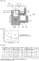
- Fig. 4 shows a graph that represents a valve opening pressure-oil temperature characteristics of the oil jet 100 according to the present embodiment, and its longitudinal axis is the oil pressure and its horizontal axis is the oil temperature.
- the valve opening pressure is self-regulated mechanically so as to be lower with an increase in the oil temperature and so as to be higher with a decrease in the oil temperature, as shown in the graph.
- the operational range of the oil jet 100 is divided into four ranges according to the oil temperature and oil pressure.
- the operation of the oil jet 100 in each operational range and the effects thereof will be described with reference to a table shown in Fig. 5 .
- the operational range (1) is a low-oil-temperature and low-oil-pressure range. This can be also said to be a low-oil-temperature and low-engine-speed range since the oil pressure changes in accordance with the engine speed.
- the oil viscosity is high at the time of low oil temperature, and therefore, the oil that has passed through the orifice 26 to flow into the differential pressure room 24 is hard to be leaked from the leak hole 28. Accordingly, the oil pressure in the differential pressure room 24 becomes high, and the valve opening pressure of the piston valve 16 becomes high.
- the piston valve 16 is not opened in a low engine speed range during which the oil pressure in the oil passage 42 is low, and no oil injection by the first oil injection nozzle 12 is performed.
- An internal combustion engine in the operational range (1) does not need cooling by the oil because the temperature of a piston in the internal combustion engine is low. Instead a stopping of oil injection from the first oil injection nozzle 12 can prevent the piston from being excessively cooled.
- the operational range (2) is a low-oil-temperature and high-oil-pressure range, that is to say, a low-oil-temperature and high-engine-speed range. A situation in which an internal combustion engine in a cold state is operated at high engine speed is included in this range, and the temperature of a piston rises to a level which needs cooling.
- the piston valve 16 is opened when the oil pressure in the oil passage 42 exceeds a valve opening pressure, and thereby, oil injection by the first oil injection nozzle 12 is performed. This allows a piston that has become high in temperature to effectively be cooled.
- the operational range (3) is a high-oil-temperature and low-oil-pressure range, that is to say, a high-oil-temperature and low-engine-speed range.
- the oil viscosity is low at the time of high oil temperature, and therefore, the oil that has passed through the orifice 26 to flow into the differential pressure room 24 is easy to be leaked from the leak hole 28. Accordingly, the oil pressure in the differential pressure room 24 becomes low, and the valve opening pressure of the piston valve 16 becomes low.
- the piston valve 16, however, is not opened because the oil pressure in the oil passage 42 is also low in a low engine speed range, and no oil injection by the first oil injection nozzle 12 is performed.
- the operational range (4) is a high-oil-temperature and high-oil-pressure range, that is to say, a high-oil-temperature and high-engine-speed range.
- the oil pressure in the oil passage 42 becomes high, whereas a valve opening pressure of the piston valve 16 becomes low because the oil becomes easy to be leaked from the leak hole 28 due to a decrease in oil viscosity. Because of this, the piston valve 16 is easily opened to perform oil injection by the first oil injection nozzle 12, and thereby, a piston that has become high in temperature is effectively cooled.
- the oil jet 100 according to the present embodiment can surely perform oil injection from the first oil injection nozzle 12 in operational ranges which need cooling of a piston of an internal combustion engine, and surely stop the oil injection in operational ranges which do not need cooling of the piston. Further, according to the oil jet 100 of the present embodiment, oil injection which is needed can be surely performed, even if a failure should occur, specifically, even if the spring 18 for moving the piston valve 16 should be broken. More specifically, since the spring 18 is biasing the piston valve 16 in a direction blocking the valve opening, a biasing force thereof disappears when the spring 18 has been broken, and thereby, the piston valve 16 is opened at a lower oil pressure. This allows oil injection for a piston to be surely performed, and therefore, an occurrence of troubles, such as seizure of the piston, due to a failure of the oil jet 100 is prevented.
- oil injection is performed toward the cylinder bore from the second oil injection nozzle 30, although there is a difference in injection momentum due to the influences of the opening and closing of the piston valve 16 and the magnitude of viscosity of the oil. Therefore, the oil that is leaked outside from the leak hole 28, which is provided for ensuring that the valve opening pressure can be self-regulated mechanically in accordance with the oil temperature, can be effectively utilized for lubrication of the cylinder bore unlike a case of simply leaking.
- the oil jet 100 includes: the first oil injection nozzle 12 that is configured to inject oil to the back side of the piston of the internal combustion engine in an operational range in which cooling of the piston is required; and the second oil injection nozzle 30 that is configured to constantly inject oil to the cylinder bore.
- the leak hole 28 and the second oil injection nozzle 30 that is connected thereto are provided at the side surface of the cylinder 4.
- the leak hole 28 can be prevented from being clogged by the foreign matter since the foreign matter moves to the bottom portion of the cylinder 4 due to the action of its own weight. Therefore, injection of the oil from the second oil injection nozzle 30 for the cylinder bore can be stably performed.
- an occurrence of trouble with respect to mechanical self-adjustment for the valve opening pressure due to the clogging of the leak hole 28 by a foreign matter can be prevented.
- the resistance to foreign matter can be improved by use of a simple configuration, without a need to install inside the oil jet 100 a member for removing a foreign matter, such as a filter.
- the second oil injection nozzle 30 is included as a member to inject oil toward the cylinder bore. If, however, another portion that is other than the cylinder bore and that constantly requires an oil supply is present due to a reason such as that oil is more likely to run short, the distal end of the second oil injection nozzle according to the present invention may be directed with respect to such portion.
Landscapes
- Engineering & Computer Science (AREA)
- Mechanical Engineering (AREA)
- General Engineering & Computer Science (AREA)
- Chemical & Material Sciences (AREA)
- Combustion & Propulsion (AREA)
- Lubrication Of Internal Combustion Engines (AREA)
Applications Claiming Priority (2)
| Application Number | Priority Date | Filing Date | Title |
|---|---|---|---|
| JP2013166806A JP6148111B2 (ja) | 2013-08-09 | 2013-08-09 | オイルジェット |
| PCT/JP2014/065216 WO2015019697A1 (ja) | 2013-08-09 | 2014-06-09 | オイルジェット |
Publications (3)
| Publication Number | Publication Date |
|---|---|
| EP3032055A1 EP3032055A1 (en) | 2016-06-15 |
| EP3032055A4 EP3032055A4 (en) | 2017-02-01 |
| EP3032055B1 true EP3032055B1 (en) | 2018-01-10 |
Family
ID=52461041
Family Applications (1)
| Application Number | Title | Priority Date | Filing Date |
|---|---|---|---|
| EP14835261.0A Not-in-force EP3032055B1 (en) | 2013-08-09 | 2014-06-09 | Oil jet |
Country Status (5)
| Country | Link |
|---|---|
| US (1) | US10233816B2 (enExample) |
| EP (1) | EP3032055B1 (enExample) |
| JP (1) | JP6148111B2 (enExample) |
| CN (1) | CN105452619B (enExample) |
| WO (1) | WO2015019697A1 (enExample) |
Families Citing this family (16)
| Publication number | Priority date | Publication date | Assignee | Title |
|---|---|---|---|---|
| DE102014005364A1 (de) * | 2014-04-11 | 2015-10-29 | Mahle International Gmbh | Baueinheit aus einem Kolben und einer Ölspritzdüse für einen Verbrennungsmotor |
| CN105545443A (zh) * | 2015-12-31 | 2016-05-04 | 潍柴动力扬州柴油机有限责任公司 | 一种活塞冷却喷嘴 |
| CN106091010B (zh) * | 2016-06-21 | 2019-03-08 | 中国航空工业集团公司沈阳发动机设计研究所 | 一种发动机燃烧室双油路喷嘴活门 |
| CN106285895A (zh) * | 2016-08-29 | 2017-01-04 | 潍柴动力股份有限公司 | 一种发动机及活塞冷却喷嘴总成 |
| DE102016219857A1 (de) * | 2016-10-12 | 2018-04-12 | Bayerische Motoren Werke Aktiengesellschaft | Vorrichtung zur Kühlung eines Kolbens einer Hubkolben-Brennkraftmaschine |
| DE102016221353A1 (de) * | 2016-10-28 | 2018-05-03 | Mahle International Gmbh | Brennkraftmaschine |
| AT519000B1 (de) * | 2016-10-31 | 2018-03-15 | Avl List Gmbh | Brennkraftmaschine |
| DE102017201905B4 (de) | 2017-02-07 | 2022-05-05 | Wagner Gmbh & Co. Kg | Steuerventil für Düsen und Düsenkopf mit dem Steuerventil |
| DE102017212547A1 (de) * | 2017-07-21 | 2019-01-24 | Bayerische Motoren Werke Aktiengesellschaft | Hubkolben-Brennkraftmaschine |
| DE102017123664A1 (de) * | 2017-10-11 | 2019-04-11 | Man Truck & Bus Ag | Ventil zum Einstellen eines Kühlfluidflusses zur Kolbenkühlung |
| US10590830B1 (en) * | 2018-10-23 | 2020-03-17 | GM Global Technology Operations LLC | Internal combustion engine including piston cooling jets |
| US11248515B2 (en) * | 2019-08-02 | 2022-02-15 | Transportation Ip Holdings, Llc | Piston cooling jet system |
| DE102020208867A1 (de) * | 2020-07-16 | 2022-01-20 | Volkswagen Aktiengesellschaft | Diagnoseverfahren für ein Kolbenkühldüsenventil, Diagnosevorrichtung, Steuergerät, Kraftfahrzeug |
| CN112031910A (zh) * | 2020-09-30 | 2020-12-04 | 广西玉柴机器股份有限公司 | 一种分级开启的喷钩布置方法及结构 |
| KR20220159159A (ko) * | 2021-05-25 | 2022-12-02 | 현대자동차주식회사 | 엔진의 피스톤 쿨링 장치 및 그 제어 방법 |
| KR20230021912A (ko) * | 2021-08-06 | 2023-02-14 | 현대자동차주식회사 | Pcj 솔레노이드밸브 진단 방법 |
Family Cites Families (40)
| Publication number | Priority date | Publication date | Assignee | Title |
|---|---|---|---|---|
| DE2546273C2 (de) * | 1975-10-16 | 1984-11-22 | Audi Nsu Auto Union Ag, 7107 Neckarsulm | Vorrichtung zur Regelung der Kolbenölkühlung für eine Kolbenbrennkraftmaschine |
| US4206726A (en) * | 1977-07-18 | 1980-06-10 | Caterpillar Tractor Co. | Double orifice piston cooling nozzle for reciprocating engines |
| US4276960A (en) * | 1979-05-17 | 1981-07-07 | Ingersoll-Rand Company | Oil distributing means |
| US4508065A (en) * | 1983-03-21 | 1985-04-02 | General Motors Corporation | Piston cooling oil delivery tube assembly |
| JPS61138816A (ja) * | 1984-12-07 | 1986-06-26 | Toyota Motor Corp | 直噴式内燃機関の燃料蒸発率制御装置 |
| JPH04121457A (ja) * | 1990-09-11 | 1992-04-22 | Zexel Corp | 自動変速装置付車輛のエンジン始動装置 |
| JP2822790B2 (ja) | 1992-07-22 | 1998-11-11 | 日産自動車株式会社 | 内燃機関のピストン冷却装置 |
| JP3447782B2 (ja) * | 1993-01-19 | 2003-09-16 | トヨタ自動車株式会社 | 内燃機関の潤滑装置 |
| JP3106058B2 (ja) * | 1994-05-20 | 2000-11-06 | 株式会社ユニシアジェックス | 内燃機関における潤滑・冷却装置 |
| JP3161282B2 (ja) | 1995-05-31 | 2001-04-25 | 日産自動車株式会社 | 内燃機関のピストン冷却装置 |
| DE19633167A1 (de) * | 1996-08-17 | 1998-02-19 | Porsche Ag | Spritzdüse für die Kolbenkühlung einer Brennkraftmaschine |
| US5819692A (en) * | 1997-05-01 | 1998-10-13 | Schafer; Timothy Vernon | Piston cooling oil control valve |
| DE19943516B4 (de) * | 1999-09-11 | 2017-01-19 | Schaeffler Technologies AG & Co. KG | Düsenventil |
| US6488479B1 (en) * | 2001-05-17 | 2002-12-03 | Ford Global Technologies, Inc. | Variable pressure oil pump |
| FR2827009B1 (fr) * | 2001-07-04 | 2003-12-12 | Bontaz Centre Sa | Gicleur de refroidissement a piston |
| FR2844003B1 (fr) * | 2002-09-02 | 2006-06-16 | Bontaz Centre Sa | Gicleur a projections multiples pour refroidissement de moteur, et moteurs equipes de tels gicleurs |
| GB2403852B (en) * | 2003-07-07 | 2006-05-31 | Electrolux Outdoor Prod Ltd | Starter |
| US7152623B2 (en) * | 2003-09-09 | 2006-12-26 | Metaldyne Company, Llc | Fluid jet for providing fluid under pressure to a desired location |
| FR2859756B1 (fr) * | 2003-09-16 | 2007-09-21 | Bontaz Centre Sa | Dispositif de refroidissement pour pistons de moteur. |
| JP2006138307A (ja) * | 2004-10-15 | 2006-06-01 | Toyota Motor Corp | 内燃機関の潤滑装置 |
| DE102005043232A1 (de) * | 2005-09-09 | 2007-03-15 | Bayerische Motoren Werke Ag | Vorrichtung zum Starten des Motors eines Kraftfahrzeugs |
| JP2007113460A (ja) * | 2005-10-19 | 2007-05-10 | Nissan Motor Co Ltd | エンジン始動制御装置およびエンジン始動制御方法。 |
| JP4333690B2 (ja) * | 2006-05-12 | 2009-09-16 | 株式会社デンソー | エンジン始動制御システム |
| DE102009006963A1 (de) * | 2009-01-31 | 2010-08-05 | Dr. Ing. H.C. F. Porsche Aktiengesellschaft | Ölversorgungseinrichtung |
| JP2011012619A (ja) * | 2009-07-03 | 2011-01-20 | Matsumoto Jukogyo Kk | オイルジェット |
| JP5312235B2 (ja) | 2009-07-06 | 2013-10-09 | 松本重工業株式会社 | オイルジェット |
| JP5190428B2 (ja) | 2009-09-18 | 2013-04-24 | 日立オートモティブシステムズ株式会社 | 内燃機関用ピストンの冷却装置 |
| US8171907B2 (en) * | 2009-11-19 | 2012-05-08 | Briggs And Stratton Corporation | Push button starting system for outdoor power equipment |
| US8707927B2 (en) * | 2011-07-20 | 2014-04-29 | GM Global Technology Operations LLC | Oil squirter |
| JP5827164B2 (ja) * | 2012-04-04 | 2015-12-02 | トヨタ自動車株式会社 | オイルジェット |
| JP5680601B2 (ja) | 2012-09-29 | 2015-03-04 | 大豊工業株式会社 | ピストンクーリングジェット |
| JP6011518B2 (ja) * | 2013-11-21 | 2016-10-19 | トヨタ自動車株式会社 | 車両用制御装置、制御方法 |
| JP6171917B2 (ja) * | 2013-12-18 | 2017-08-02 | 株式会社デンソー | エンジン始動装置 |
| US9404466B2 (en) * | 2014-06-14 | 2016-08-02 | GM Global Technology Operations LLC | Method for evaluating an engine starting system |
| US9401053B2 (en) * | 2014-09-09 | 2016-07-26 | GM Global Technology Operations LLC | Fault notifications for vehicles |
| US9790910B2 (en) * | 2015-01-13 | 2017-10-17 | Toyota Motor Engineering & Manufacturing North America, Inc. | System and method for preventing unwanted engine restarts while parking a vehicle |
| JP2016194270A (ja) * | 2015-03-31 | 2016-11-17 | トヨタ自動車株式会社 | エンジン自動制御装置 |
| JP2016200051A (ja) * | 2015-04-09 | 2016-12-01 | トヨタ自動車株式会社 | エンジン始動制御装置 |
| US9758171B2 (en) * | 2015-06-15 | 2017-09-12 | GM Global Technology Operations LLC | Method and apparatus for controlling a multi-mode powertrain system including an engine having stop/start capability |
| US9951704B2 (en) * | 2015-09-08 | 2018-04-24 | GM Global Technology Operations LLC | No start event monitoring |
-
2013
- 2013-08-09 JP JP2013166806A patent/JP6148111B2/ja not_active Expired - Fee Related
-
2014
- 2014-06-09 WO PCT/JP2014/065216 patent/WO2015019697A1/ja not_active Ceased
- 2014-06-09 CN CN201480044704.7A patent/CN105452619B/zh not_active Expired - Fee Related
- 2014-06-09 US US14/910,857 patent/US10233816B2/en active Active
- 2014-06-09 EP EP14835261.0A patent/EP3032055B1/en not_active Not-in-force
Non-Patent Citations (1)
| Title |
|---|
| None * |
Also Published As
| Publication number | Publication date |
|---|---|
| EP3032055A1 (en) | 2016-06-15 |
| US20160186642A1 (en) | 2016-06-30 |
| US10233816B2 (en) | 2019-03-19 |
| JP2015034537A (ja) | 2015-02-19 |
| CN105452619A (zh) | 2016-03-30 |
| CN105452619B (zh) | 2018-03-06 |
| WO2015019697A1 (ja) | 2015-02-12 |
| EP3032055A4 (en) | 2017-02-01 |
| JP6148111B2 (ja) | 2017-06-14 |
Similar Documents
| Publication | Publication Date | Title |
|---|---|---|
| EP3032055B1 (en) | Oil jet | |
| EP2754862B1 (en) | Oil jet | |
| US7849836B2 (en) | Cooling feature for fuel injector and fuel system using same | |
| JP5680601B2 (ja) | ピストンクーリングジェット | |
| KR950033016A (ko) | 내연 기관용 연료 분사 장치 | |
| US20150122340A1 (en) | Biased normally open check valve assembly | |
| GB2484748A (en) | Oil Supply Control for Internal Combustion Engine Pistons | |
| CN102383995B (zh) | 被动限量阀和大型柴油发动机 | |
| BR112018009703B1 (pt) | Filtro de óleo para veículo motorizado e cartucho de filtro para instalação no invólucro do filtro de óleo do filtro de óleo | |
| US6168091B1 (en) | Low noise electronically actuated oil valve and fuel injector using same | |
| JP6144750B2 (ja) | 燃料噴射器 | |
| US20130233271A1 (en) | Oil squirter with damping vent | |
| US9297343B2 (en) | Needle for needle valve | |
| JP2004068727A (ja) | 燃料噴射装置 | |
| EP3743617A1 (en) | Fuel pump | |
| JP2013217202A (ja) | オイルジェット | |
| JP6635461B2 (ja) | 潤滑システム | |
| EP2256392B1 (en) | Valve arrangement | |
| JP2014009603A (ja) | オイルジェット | |
| JP2013249742A (ja) | オイルジェット | |
| JP2014070610A (ja) | ピストンクーリングジェット | |
| KR101999908B1 (ko) | 내연 기관용 연료 분사 유닛 | |
| CN110892146A (zh) | 高压燃料泵 | |
| CN204436504U (zh) | 发动机气门驱动装置 | |
| CA2494294C (en) | Fuel injection nozzle |
Legal Events
| Date | Code | Title | Description |
|---|---|---|---|
| PUAI | Public reference made under article 153(3) epc to a published international application that has entered the european phase |
Free format text: ORIGINAL CODE: 0009012 |
|
| 17P | Request for examination filed |
Effective date: 20160209 |
|
| AK | Designated contracting states |
Kind code of ref document: A1 Designated state(s): AL AT BE BG CH CY CZ DE DK EE ES FI FR GB GR HR HU IE IS IT LI LT LU LV MC MK MT NL NO PL PT RO RS SE SI SK SM TR |
|
| AX | Request for extension of the european patent |
Extension state: BA ME |
|
| DAX | Request for extension of the european patent (deleted) | ||
| A4 | Supplementary search report drawn up and despatched |
Effective date: 20170105 |
|
| RIC1 | Information provided on ipc code assigned before grant |
Ipc: F01P 3/08 20060101ALI20161223BHEP Ipc: F01M 1/08 20060101AFI20161223BHEP |
|
| GRAP | Despatch of communication of intention to grant a patent |
Free format text: ORIGINAL CODE: EPIDOSNIGR1 |
|
| INTG | Intention to grant announced |
Effective date: 20170802 |
|
| GRAS | Grant fee paid |
Free format text: ORIGINAL CODE: EPIDOSNIGR3 |
|
| GRAA | (expected) grant |
Free format text: ORIGINAL CODE: 0009210 |
|
| AK | Designated contracting states |
Kind code of ref document: B1 Designated state(s): AL AT BE BG CH CY CZ DE DK EE ES FI FR GB GR HR HU IE IS IT LI LT LU LV MC MK MT NL NO PL PT RO RS SE SI SK SM TR |
|
| REG | Reference to a national code |
Ref country code: CH Ref legal event code: EP Ref country code: AT Ref legal event code: REF Ref document number: 962653 Country of ref document: AT Kind code of ref document: T Effective date: 20180115 |
|
| REG | Reference to a national code |
Ref country code: IE Ref legal event code: FG4D |
|
| REG | Reference to a national code |
Ref country code: DE Ref legal event code: R096 Ref document number: 602014019935 Country of ref document: DE |
|
| REG | Reference to a national code |
Ref country code: FR Ref legal event code: PLFP Year of fee payment: 5 |
|
| REG | Reference to a national code |
Ref country code: NL Ref legal event code: MP Effective date: 20180110 |
|
| REG | Reference to a national code |
Ref country code: AT Ref legal event code: MK05 Ref document number: 962653 Country of ref document: AT Kind code of ref document: T Effective date: 20180110 |
|
| PG25 | Lapsed in a contracting state [announced via postgrant information from national office to epo] |
Ref country code: NL Free format text: LAPSE BECAUSE OF FAILURE TO SUBMIT A TRANSLATION OF THE DESCRIPTION OR TO PAY THE FEE WITHIN THE PRESCRIBED TIME-LIMIT Effective date: 20180110 |
|
| PG25 | Lapsed in a contracting state [announced via postgrant information from national office to epo] |
Ref country code: HR Free format text: LAPSE BECAUSE OF FAILURE TO SUBMIT A TRANSLATION OF THE DESCRIPTION OR TO PAY THE FEE WITHIN THE PRESCRIBED TIME-LIMIT Effective date: 20180110 Ref country code: LT Free format text: LAPSE BECAUSE OF FAILURE TO SUBMIT A TRANSLATION OF THE DESCRIPTION OR TO PAY THE FEE WITHIN THE PRESCRIBED TIME-LIMIT Effective date: 20180110 Ref country code: ES Free format text: LAPSE BECAUSE OF FAILURE TO SUBMIT A TRANSLATION OF THE DESCRIPTION OR TO PAY THE FEE WITHIN THE PRESCRIBED TIME-LIMIT Effective date: 20180110 Ref country code: CY Free format text: LAPSE BECAUSE OF FAILURE TO SUBMIT A TRANSLATION OF THE DESCRIPTION OR TO PAY THE FEE WITHIN THE PRESCRIBED TIME-LIMIT Effective date: 20180110 Ref country code: FI Free format text: LAPSE BECAUSE OF FAILURE TO SUBMIT A TRANSLATION OF THE DESCRIPTION OR TO PAY THE FEE WITHIN THE PRESCRIBED TIME-LIMIT Effective date: 20180110 Ref country code: NO Free format text: LAPSE BECAUSE OF FAILURE TO SUBMIT A TRANSLATION OF THE DESCRIPTION OR TO PAY THE FEE WITHIN THE PRESCRIBED TIME-LIMIT Effective date: 20180410 |
|
| PG25 | Lapsed in a contracting state [announced via postgrant information from national office to epo] |
Ref country code: AT Free format text: LAPSE BECAUSE OF FAILURE TO SUBMIT A TRANSLATION OF THE DESCRIPTION OR TO PAY THE FEE WITHIN THE PRESCRIBED TIME-LIMIT Effective date: 20180110 Ref country code: RS Free format text: LAPSE BECAUSE OF FAILURE TO SUBMIT A TRANSLATION OF THE DESCRIPTION OR TO PAY THE FEE WITHIN THE PRESCRIBED TIME-LIMIT Effective date: 20180110 Ref country code: BG Free format text: LAPSE BECAUSE OF FAILURE TO SUBMIT A TRANSLATION OF THE DESCRIPTION OR TO PAY THE FEE WITHIN THE PRESCRIBED TIME-LIMIT Effective date: 20180410 Ref country code: PL Free format text: LAPSE BECAUSE OF FAILURE TO SUBMIT A TRANSLATION OF THE DESCRIPTION OR TO PAY THE FEE WITHIN THE PRESCRIBED TIME-LIMIT Effective date: 20180110 Ref country code: GR Free format text: LAPSE BECAUSE OF FAILURE TO SUBMIT A TRANSLATION OF THE DESCRIPTION OR TO PAY THE FEE WITHIN THE PRESCRIBED TIME-LIMIT Effective date: 20180411 Ref country code: LV Free format text: LAPSE BECAUSE OF FAILURE TO SUBMIT A TRANSLATION OF THE DESCRIPTION OR TO PAY THE FEE WITHIN THE PRESCRIBED TIME-LIMIT Effective date: 20180110 Ref country code: IS Free format text: LAPSE BECAUSE OF FAILURE TO SUBMIT A TRANSLATION OF THE DESCRIPTION OR TO PAY THE FEE WITHIN THE PRESCRIBED TIME-LIMIT Effective date: 20180510 Ref country code: SE Free format text: LAPSE BECAUSE OF FAILURE TO SUBMIT A TRANSLATION OF THE DESCRIPTION OR TO PAY THE FEE WITHIN THE PRESCRIBED TIME-LIMIT Effective date: 20180110 |
|
| REG | Reference to a national code |
Ref country code: DE Ref legal event code: R097 Ref document number: 602014019935 Country of ref document: DE |
|
| PG25 | Lapsed in a contracting state [announced via postgrant information from national office to epo] |
Ref country code: AL Free format text: LAPSE BECAUSE OF FAILURE TO SUBMIT A TRANSLATION OF THE DESCRIPTION OR TO PAY THE FEE WITHIN THE PRESCRIBED TIME-LIMIT Effective date: 20180110 Ref country code: RO Free format text: LAPSE BECAUSE OF FAILURE TO SUBMIT A TRANSLATION OF THE DESCRIPTION OR TO PAY THE FEE WITHIN THE PRESCRIBED TIME-LIMIT Effective date: 20180110 Ref country code: EE Free format text: LAPSE BECAUSE OF FAILURE TO SUBMIT A TRANSLATION OF THE DESCRIPTION OR TO PAY THE FEE WITHIN THE PRESCRIBED TIME-LIMIT Effective date: 20180110 Ref country code: IT Free format text: LAPSE BECAUSE OF FAILURE TO SUBMIT A TRANSLATION OF THE DESCRIPTION OR TO PAY THE FEE WITHIN THE PRESCRIBED TIME-LIMIT Effective date: 20180110 |
|
| PLBE | No opposition filed within time limit |
Free format text: ORIGINAL CODE: 0009261 |
|
| STAA | Information on the status of an ep patent application or granted ep patent |
Free format text: STATUS: NO OPPOSITION FILED WITHIN TIME LIMIT |
|
| PG25 | Lapsed in a contracting state [announced via postgrant information from national office to epo] |
Ref country code: SK Free format text: LAPSE BECAUSE OF FAILURE TO SUBMIT A TRANSLATION OF THE DESCRIPTION OR TO PAY THE FEE WITHIN THE PRESCRIBED TIME-LIMIT Effective date: 20180110 Ref country code: DK Free format text: LAPSE BECAUSE OF FAILURE TO SUBMIT A TRANSLATION OF THE DESCRIPTION OR TO PAY THE FEE WITHIN THE PRESCRIBED TIME-LIMIT Effective date: 20180110 Ref country code: SM Free format text: LAPSE BECAUSE OF FAILURE TO SUBMIT A TRANSLATION OF THE DESCRIPTION OR TO PAY THE FEE WITHIN THE PRESCRIBED TIME-LIMIT Effective date: 20180110 Ref country code: CZ Free format text: LAPSE BECAUSE OF FAILURE TO SUBMIT A TRANSLATION OF THE DESCRIPTION OR TO PAY THE FEE WITHIN THE PRESCRIBED TIME-LIMIT Effective date: 20180110 |
|
| 26N | No opposition filed |
Effective date: 20181011 |
|
| REG | Reference to a national code |
Ref country code: CH Ref legal event code: PL |
|
| PG25 | Lapsed in a contracting state [announced via postgrant information from national office to epo] |
Ref country code: SI Free format text: LAPSE BECAUSE OF FAILURE TO SUBMIT A TRANSLATION OF THE DESCRIPTION OR TO PAY THE FEE WITHIN THE PRESCRIBED TIME-LIMIT Effective date: 20180110 |
|
| REG | Reference to a national code |
Ref country code: BE Ref legal event code: MM Effective date: 20180630 |
|
| REG | Reference to a national code |
Ref country code: IE Ref legal event code: MM4A |
|
| PG25 | Lapsed in a contracting state [announced via postgrant information from national office to epo] |
Ref country code: LU Free format text: LAPSE BECAUSE OF NON-PAYMENT OF DUE FEES Effective date: 20180609 Ref country code: MC Free format text: LAPSE BECAUSE OF FAILURE TO SUBMIT A TRANSLATION OF THE DESCRIPTION OR TO PAY THE FEE WITHIN THE PRESCRIBED TIME-LIMIT Effective date: 20180110 |
|
| PG25 | Lapsed in a contracting state [announced via postgrant information from national office to epo] |
Ref country code: LI Free format text: LAPSE BECAUSE OF NON-PAYMENT OF DUE FEES Effective date: 20180630 Ref country code: CH Free format text: LAPSE BECAUSE OF NON-PAYMENT OF DUE FEES Effective date: 20180630 Ref country code: IE Free format text: LAPSE BECAUSE OF NON-PAYMENT OF DUE FEES Effective date: 20180609 |
|
| PG25 | Lapsed in a contracting state [announced via postgrant information from national office to epo] |
Ref country code: BE Free format text: LAPSE BECAUSE OF NON-PAYMENT OF DUE FEES Effective date: 20180630 |
|
| PG25 | Lapsed in a contracting state [announced via postgrant information from national office to epo] |
Ref country code: MT Free format text: LAPSE BECAUSE OF NON-PAYMENT OF DUE FEES Effective date: 20180609 |
|
| PG25 | Lapsed in a contracting state [announced via postgrant information from national office to epo] |
Ref country code: TR Free format text: LAPSE BECAUSE OF FAILURE TO SUBMIT A TRANSLATION OF THE DESCRIPTION OR TO PAY THE FEE WITHIN THE PRESCRIBED TIME-LIMIT Effective date: 20180110 |
|
| PG25 | Lapsed in a contracting state [announced via postgrant information from national office to epo] |
Ref country code: PT Free format text: LAPSE BECAUSE OF FAILURE TO SUBMIT A TRANSLATION OF THE DESCRIPTION OR TO PAY THE FEE WITHIN THE PRESCRIBED TIME-LIMIT Effective date: 20180110 |
|
| PG25 | Lapsed in a contracting state [announced via postgrant information from national office to epo] |
Ref country code: MK Free format text: LAPSE BECAUSE OF NON-PAYMENT OF DUE FEES Effective date: 20180110 Ref country code: HU Free format text: LAPSE BECAUSE OF FAILURE TO SUBMIT A TRANSLATION OF THE DESCRIPTION OR TO PAY THE FEE WITHIN THE PRESCRIBED TIME-LIMIT; INVALID AB INITIO Effective date: 20140609 |
|
| PGFP | Annual fee paid to national office [announced via postgrant information from national office to epo] |
Ref country code: GB Payment date: 20220428 Year of fee payment: 9 Ref country code: FR Payment date: 20220510 Year of fee payment: 9 Ref country code: DE Payment date: 20220505 Year of fee payment: 9 |
|
| REG | Reference to a national code |
Ref country code: DE Ref legal event code: R119 Ref document number: 602014019935 Country of ref document: DE |
|
| GBPC | Gb: european patent ceased through non-payment of renewal fee |
Effective date: 20230609 |
|
| PG25 | Lapsed in a contracting state [announced via postgrant information from national office to epo] |
Ref country code: DE Free format text: LAPSE BECAUSE OF NON-PAYMENT OF DUE FEES Effective date: 20240103 Ref country code: GB Free format text: LAPSE BECAUSE OF NON-PAYMENT OF DUE FEES Effective date: 20230609 |
|
| PG25 | Lapsed in a contracting state [announced via postgrant information from national office to epo] |
Ref country code: FR Free format text: LAPSE BECAUSE OF NON-PAYMENT OF DUE FEES Effective date: 20230630 |