EP3031602A1 - Transparentes laminat und schützendes werkzeug damit - Google Patents
Transparentes laminat und schützendes werkzeug damit Download PDFInfo
- Publication number
- EP3031602A1 EP3031602A1 EP14834273.6A EP14834273A EP3031602A1 EP 3031602 A1 EP3031602 A1 EP 3031602A1 EP 14834273 A EP14834273 A EP 14834273A EP 3031602 A1 EP3031602 A1 EP 3031602A1
- Authority
- EP
- European Patent Office
- Prior art keywords
- transparent laminate
- filmy
- adhesive
- overlapped
- structures
- Prior art date
- Legal status (The legal status is an assumption and is not a legal conclusion. Google has not performed a legal analysis and makes no representation as to the accuracy of the status listed.)
- Granted
Links
Images


Classifications
-
- B—PERFORMING OPERATIONS; TRANSPORTING
- B32—LAYERED PRODUCTS
- B32B—LAYERED PRODUCTS, i.e. PRODUCTS BUILT-UP OF STRATA OF FLAT OR NON-FLAT, e.g. CELLULAR OR HONEYCOMB, FORM
- B32B7/00—Layered products characterised by the relation between layers; Layered products characterised by the relative orientation of features between layers, or by the relative values of a measurable parameter between layers, i.e. products comprising layers having different physical, chemical or physicochemical properties; Layered products characterised by the interconnection of layers
- B32B7/04—Interconnection of layers
- B32B7/06—Interconnection of layers permitting easy separation
-
- B—PERFORMING OPERATIONS; TRANSPORTING
- B32—LAYERED PRODUCTS
- B32B—LAYERED PRODUCTS, i.e. PRODUCTS BUILT-UP OF STRATA OF FLAT OR NON-FLAT, e.g. CELLULAR OR HONEYCOMB, FORM
- B32B3/00—Layered products comprising a layer with external or internal discontinuities or unevennesses, or a layer of non-planar shape; Layered products comprising a layer having particular features of form
- B32B3/26—Layered products comprising a layer with external or internal discontinuities or unevennesses, or a layer of non-planar shape; Layered products comprising a layer having particular features of form characterised by a particular shape of the outline of the cross-section of a continuous layer; characterised by a layer with cavities or internal voids ; characterised by an apertured layer
- B32B3/30—Layered products comprising a layer with external or internal discontinuities or unevennesses, or a layer of non-planar shape; Layered products comprising a layer having particular features of form characterised by a particular shape of the outline of the cross-section of a continuous layer; characterised by a layer with cavities or internal voids ; characterised by an apertured layer characterised by a layer formed with recesses or projections, e.g. hollows, grooves, protuberances, ribs
-
- A—HUMAN NECESSITIES
- A42—HEADWEAR
- A42B—HATS; HEAD COVERINGS
- A42B3/00—Helmets; Helmet covers ; Other protective head coverings
- A42B3/04—Parts, details or accessories of helmets
- A42B3/18—Face protection devices
- A42B3/22—Visors
-
- B—PERFORMING OPERATIONS; TRANSPORTING
- B32—LAYERED PRODUCTS
- B32B—LAYERED PRODUCTS, i.e. PRODUCTS BUILT-UP OF STRATA OF FLAT OR NON-FLAT, e.g. CELLULAR OR HONEYCOMB, FORM
- B32B7/00—Layered products characterised by the relation between layers; Layered products characterised by the relative orientation of features between layers, or by the relative values of a measurable parameter between layers, i.e. products comprising layers having different physical, chemical or physicochemical properties; Layered products characterised by the interconnection of layers
- B32B7/04—Interconnection of layers
- B32B7/12—Interconnection of layers using interposed adhesives or interposed materials with bonding properties
-
- G—PHYSICS
- G02—OPTICS
- G02B—OPTICAL ELEMENTS, SYSTEMS OR APPARATUS
- G02B1/00—Optical elements characterised by the material of which they are made; Optical coatings for optical elements
- G02B1/10—Optical coatings produced by application to, or surface treatment of, optical elements
- G02B1/11—Anti-reflection coatings
- G02B1/118—Anti-reflection coatings having sub-optical wavelength surface structures designed to provide an enhanced transmittance, e.g. moth-eye structures
-
- B—PERFORMING OPERATIONS; TRANSPORTING
- B32—LAYERED PRODUCTS
- B32B—LAYERED PRODUCTS, i.e. PRODUCTS BUILT-UP OF STRATA OF FLAT OR NON-FLAT, e.g. CELLULAR OR HONEYCOMB, FORM
- B32B2307/00—Properties of the layers or laminate
- B32B2307/40—Properties of the layers or laminate having particular optical properties
- B32B2307/412—Transparent
-
- B—PERFORMING OPERATIONS; TRANSPORTING
- B32—LAYERED PRODUCTS
- B32B—LAYERED PRODUCTS, i.e. PRODUCTS BUILT-UP OF STRATA OF FLAT OR NON-FLAT, e.g. CELLULAR OR HONEYCOMB, FORM
- B32B2437/00—Clothing
- B32B2437/04—Caps, helmets
-
- B—PERFORMING OPERATIONS; TRANSPORTING
- B32—LAYERED PRODUCTS
- B32B—LAYERED PRODUCTS, i.e. PRODUCTS BUILT-UP OF STRATA OF FLAT OR NON-FLAT, e.g. CELLULAR OR HONEYCOMB, FORM
- B32B2571/00—Protective equipment
Definitions
- This invention relates to a transparent laminate characterized in that, e.g., plural filmy members are pasted and overlapped with a space between the overlapped members at least at a part area of the filmy member, which is formed with a plurality of structures arranged with a pitch not greater than a visible light wave length on at least one side of a flexible base, and to a protection tool using the same.
- a surface of a conventional shield for a helmet used for motorcycle racing and motor racing may be suffer from dirtiness in a short time, thereby disturbing the vision field occasionally.
- a protection google for painting used during painting work may receive e.g., scattered paint during the painting work, so that the surface of the google may get dirty as to disturb the vision field.
- a surface of a medical glass or a face shield may get dirty from blood scattered from a patient during the operation.
- Patent Document # 1 is a protection device for a shield portion of a helmet attaching a plurality of sheet like protection covers, or namely, a disposable visor, so as to cover the shield portion of the helmet.
- the protection device is configured to simply have an overlapping structure of protection films, however, reflections may occur at boundaries between layers where overlapped. There also raises a problem such that the transparency is simply lowered as the overlapping number increases, or namely the overlapping sheet number may be limited.
- transparent plastic films can be used generally.
- plastic films generally used are films having a refractive index of 1.4 to 1.6, having a light reflection of 4% to 5% on each of the double sides of the film, and having an entire transmittance of 90% to 92%.
- a single film has a transmittance of around 90%, but 81% when two films are overlapped, and 73% when three films are overlapped, so that there raises a problem lowering the light transmittance to make visibility worse as the sheet number of the films increases.
- Such a moth-eye structure has an advantage that the color tone may not change when an object is viewed through the moth-eye structure because of corresponding to the entire wavelength basically as different from antireflection films used for liquid crystal displays corresponding to particular wavelength or wavelengths.
- Patent Document #3 discloses a low reflection transparent plate and a display casing using the plate realizing a low reflectance from a moth-eye effect provided from the surface fine structure.
- the optical property may be lowered from breakdown or the like of the structure due to friction as nature of the resin where the moth-eye structure is obtained with the ultraviolet curable resin.
- a shield of a helmet, a google, and a protection glass it is therefore not desirable to wipe off stains where such stains disturbing visual recognition are attached onto the surface thereof.
- This invention is made in consideration of solving the above technical problems as described above. It is an object of the invention to provide a transparent laminate and a protection tool using the same, with overlapping filmy members having a moth-eye structure, to prevent the reflectance from becoming higher and the transmittance from becoming lower, not to lose instantaneousness of peeling and easiness, to improve mold releasing property of an adhesive by limiting an adhering area such as forming with, e.g., a narrower width, to avoid occurrences of deformation of the adhesive thickness, and to ensure the visual recognition property.
- a transparent laminate according to a first aspect of the invention includes a plurality of filmy members each configured to be formed on at least one side of a base with structures having protrusions and recesses whose pitch is equal to or less than visible light wavelength, wherein the filmy members are overlapped via an adhesive layer at least at an end thereof, and wherein the overlapped filmy members are provided with a space arranged between the structures facing each other.
- a protection tool according to a second aspect of the invention is formed with the transparent laminate at a visual recognition area.
- the transparent laminate and the protection tool using the same according to the invention can prevent the reflectance from becoming higher and the transmittance from becoming lower, not lose instantaneousness of peeling and easiness, improve mold releasing property of an adhesive by limiting an adhering area such as forming with, e.g., a narrower width, avoid occurrences of deformation of the adhesive thickness, and ensure the visual recognition property.
- a structure is formed on double sides of a flexible base with a pitch not more than visible light wavelength.
- the fine protrusion and recess structure having an antireflection function is hereinafter called to as "moth-eye structure.”
- a space can be produced between the filmy members when the plural filmy members are overlapped.
- An adhering area of the adhesive layer of the filmy members can be designed properly to form the prescribed space between the structures.
- the adhesive layer is formed only at an end or ends; the adhesive layer can be formed in lines or dots, and further formed in both of lines and dots.
- the adhesive layer may be formed not only at the ends of the filmy member, including an arrangement extending the entire surface, and in this case, peeling property may be different between the ends and areas other than the ends. Areas other than the ends are desirably required to have a weaker peeling property than the ends.
- the end of the filmy member or a part of the end may be physically secured and overlapped.
- securing or immobilizing can be made with pins or in engagement with immobilized pins or hooks, in a state that the filmy members are overlapped.
- the secured portion formed at the end or a part of the end is required to be made as to settle the transparent laminate.
- a part of the filmy member may be fabricated with such as a cut.
- the laminate may be secured by using an ultraviolet melting method or a heating melting method.
- the filmy members having the moth-eye structure are overlapped in this invention. Because problems of lowered transmittance and reflection on a back side of the filmy member occur with the overlapping structure of the filmy member having the moth-eye structure on only one side, the transparent laminate is structured with the filmy members having the moth-eye structure on the double sides. This makes an overlapping shield structure free from lowering of transmittance, and the overlapping number can be increases because the transparency is improved.
- the laminate having the moth-eye structure on one side is not excluded.
- Securing can be made easily where overlapping is made with the adhesive layer of, e.g., adhesive. It is desirable to form the adhesive at an outer peripheral portion, which extends outside the viewing field when attached. Where the adhesive is not formed across the entire surface of the filmy member, conditions satisfying both of feature and cost such as i) peeling property improvement of the filmy member itself, ii) peeling property improvement of the adhesive (avoiding view recognition from lowering due to residues), and iii) avoidance of deformation occurrences due to the thickness of the adhesive, can be found easily.
- the laminate in which the entire surface is adhered by the adhesive layer is not excluded.
- the protection tool with a shield can enjoy higher usability because causes for lowering the visual recognition property and all can be eliminated by peeling the filmy member when necessary even where stains make the visual recognition property low.
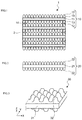
- Fig. 1 is a structural view of a transparent laminate according to an embodiment of the invention.
- a transparent laminate 1 is structured of plural filmy members 10 as optical devices, which are jointed by adhesive layers 2 made of such as adhesive.
- Each filmy member 10 has structures 12 on double sides of a base 11 via a bottom layer 13.
- the filmy member 10 serving as the optical device has the double sides, a front side and a back side, opposite to each other, which is with an antireflection function.
- the filmy member 10 includes the base 11 having the front side and back side, the bottom layers 13 overlapped on the front side and the back side of the base 11, and plural structures 12 formed via the bottom layers 13.
- the plural structures 12 are arranged regularly as to form plural lines on the bottom layer 13 on the front side and the back side of the base 11.
- the front side and the back side of the filmy member 10 have a shape of protrusions and recesses of moth-eye structures made of the plural structures 12.
- the structure 12 can be formed only on the front side.
- the front side and the back side of the filmy member 10 are surfaces of protrusions and recesses made of the moth-eye structures having the plural structures in a pitch equal to or less than the visible light wavelength.
- optical adjustment function indicates the optical adjustment function of transparency feature and reflection feature.
- the filmy member 10 serving as the optical device has a transparency with respect to, e.g., visible light, and preferably has a refraction index in a range, preferably not less than 1.30 and not more than 2.00, and more preferably not less than 1.34 and not more than 2.00. It is not limited to these ranges.
- the refraction index of the structure 12 is preferably, substantially the same as the refraction index of the adhesive layer 2 and the base 11. This is because the index can suppress interior reflections and can improve the contrast.
- the bottom layer 13 plays a role to improve adherence of the structure 12 to the base 11.
- the bottom layer 13 is an optical layer formed in a united body with the structure 12 on the bottom side of the structure 12, has a transparency, and may be formed by curing e.g., an energy ray curable resin component substantially the same as the structure 12.
- a filmy member 20 may be formed directly with the moth-eye structure made of plural structures 22 on a base 21, without any bottom layer 13.
- the base and the structures can be formed in a united body as shown in, e.g., Fig. 3 . That is, with the situation of the structure shown in Fig. 3 , the structures 32 are formed on the double sides of the base 31 in a united body to constitute a filmy member 30.
- the base 11 is further referred herein.
- the base 11 is, e.g., a transparent base having a transparency. Exemplified as a material for the base 11 are what are having a plastic material having a transparency as a main component, but the base 11 is not limited to being made of those materials.
- a primer layer not shown may be further formed from a surface process to improve surface energy, coating property, slidablity, and flatness on the surface of the plastic material.
- Exemplified as the primer layer are, e.g., organoalkoxy metal compound, polyester, acrylic-modified polyester, and polyurethane.
- a corona discharge processing or a ultraviolet radiation processing may be made to the surface of the base 11.
- the base 11 is a plastic film
- the base 11 can be made from, e.g., methods drawing the resin described above or making the resin into a film after diluting the resin in a solvent t and then drying the film.
- the thickness of the base 11 is preferably chosen according to usage of the transparent laminate 1, and can be, e.g., around not less than 50 microns and not more than 500 microns.
- the shape of the base 11 exemplified are film shape, plate shape, etc., but the shape of the base 11 is not limited to these shapes. It is to be noted that the film includes a sheet.
- a material for the base 11 exemplified are, e.g., methyl methacrylate (co)polymer, polycarbonate, styrene (co)polymer, methyl methacrylate-styrene copolymer, cellulose diacetate, cellulose triacetate, cellulose acetate butyrate, polyester, polyamide, polyimide, polyether sulfone, polysulfone, polypropylene, ploymethylpentene, polyvinyl chloride, polyvinyl acetal, polyether ketone, polyurethane, glass, etc. but the material is not limited to these.
- the wavelength range of the visible light is from 360 nm to 830 nm, and in this embodiment, the structure 12 is regularly arranged with a size not more than the wavelength range of the visible light. From this viewpoint, the arrangement pitch of the structure 12 does not exceed 350 nm.
- the structure 12 can be in various shapes such as, e.g., prism shapes, pillar shapes, and needle shapes.
- the structure 12 is formed by curing, e.g., energy ray curable resin component.
- the energy ray curable resin component forming the structure 12 may have different material features between the double sides of the base 11. For example, by using water repellant feature and hydrophilic feature differently according to the usage, a particular surface may have, e.g., an antifogging function.
- the energy ray curable resin component it is preferable to use ultraviolet curable resin component.
- the energy ray curable resin component may include fillers or functional additives as needed.
- the ultraviolet curable resin component includes, e.g., acrylate and initiator.
- the ultraviolet curable resin component includes, e.g., monofunctional monomers, bifunctional monomers, and polyfunctional monomers, and more specifically, includes a single material or a mixture of plural materials shown below.
- monomers are, e.g., carboxylic acids (acrylic acid), hydroxyls (2-hydroxyethyl acrylate, 2-hydroxylpropyl acrylate, 4-hydroxylbutyl acrylate), alkyls, alicyclic (isobutyl acrylate, t-butyl acrylate, isooctyl acrylate, lauryl acrylate, stearyl acrylate, isobonyl acrylate, cyclohexyl acrylate), and other functional monomers (2-methoxyethyl acrylate, methoxyethylene glycol acrylate, 2-etokyethyl acrylate, tetrahydrofurfuryl acrylate, benzyl acrylate, ethyl carbitol acrylate, phenoxy ethyl acrylate, N, N-dimethyl aminoethyl acrylate, N, N-dimethyl aminoprop
- bifunctional monomers exemplified are, e.g., tri(propylene glycol) diacrylate, trimethylolepropane, diallyl ether, and urethane acrylate.
- polyfunctional monomers exemplified are, e.g., trimethylolpropane triacrylate, dipentaerythritol penta(hexa)acrylate, and ditrimethyolpropane tetraacrylate.
- initiator exemplified are, e.g., 2,3-dimetoxy-1,2-diphenylethan-1-one, 1-hydroxy-cyclohexilphenylkenoton, and 2-hydroxy-2-methyl-1-phenylpropane-1-one.
- filler usable are any of inorganic particles and organic particles.
- inorganic particles exemplified are, e.g., metal oxide fine particles such as SiO 2 , TiO 2 , ZrO 2 , SnO 2 , and Al 2 O 3 .
- ком ⁇ онент exemplified are, e.g., leveling agent, surface adjusting agent, and defoaming agent.
- the transparent laminate according to this embodiment includes a plurality of filmy members 10 in which the moth-eye structures made of the structures 12 of protrusions and recesses with the pitch no more than the visible light wavelength are formed on double sides of the base 11, and at least the ends of the filmy members 10 are overlapped with the adhesive layer 2 such as an adhesive.
- the space 14 is formed between the structures 12 between the overlapped filmy members 10. As patterns of the space 14, various patterns are conceivable, but some examples are shown in Figs. 4(a) to 4(c) .
- the space 14 can be made of a resin such as an adhesive. That is, the space 14 can be an air layer as well as a resin layer.
- Fig. 4(a) shows a situation that the air layer is formed as the facing structures 12 are not in contact with each other according to the thickness of the adhesive layer 2.
- Fig. 4(b) shows a situation that the air layer is made at the recesses because the structures 12 are continuations of the protrusions and the recesses though the tips of the structures 12 facing each other are in point contact with each other.
- Fig. 4(c) shows a situation that, although the tip of the structure 12 encroaches the recess of the opposite structure 12, a prescribed air layer is formed, because the tip does not enter into the recess completely. In those situations, each air layer exists as the space. It is to be noted that the space is not limited to the air layer, and for example, where the entire surface of the structure 12 is adhered with the adhesive layer 2, the adhesive layer 2 may include the space or spaces in a broad sense as a matter of course.
- the structures 12 are arranged in a regular manner and keep regularity even when viewed in a row direction as well as a column direction, overlapping can be done well.
- the adhesive layer 2 is formed at an outer peripheral portion as to be out of the viewing field when attached, in this embodiment. That is, it is arranged at an area other than the viewing field.
- the structures 12 of the filmy member 10 may be jointed partly with the adhesive layer 2 at the four corners of the filmy members 10 or at areas extending in a shorter side direction in a prescribed width and a prescribed length at right and left ends of the filmy member 10.
- the adhesive layer 2 is not formed on the entire surface of the filmy members 10, thereby improving the peelability of the filmy member 10 itself, improving the mold releasing property of the adhesive as the adhesive layer 2 or namely avoidance of the visible recognition reduction due to residues, and avoiding deformations from occurring due to thickness of the adhesive as the adhesive layer 2. It is to be noted that if the transmittance feature is made as the top priority, it is as a matter of course to adhere the entire surface with an adhesive or the like. In this case, resin composites may be selected properly as to make good the refraction index to improve the visual recognition property.
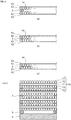
- the transparent laminate 1 according to this embodiment is an overlapped body having the moth-eye structure realizing the antireflection function provided on the double sides; the plural filmy members serving as the optical device are jointed with the plural adhesive layers; as shown in Fig. 5 , the transparent laminate 1 is adhered via a sticking layer 3 to an adherend 4.
- adherend exemplified are, e.g., visors of helmets, medical face shields, medical displays, and protection glasses for painting.
- the invention is not limited to those, and includes various optical tools used in an environment such that no one can predict arrivals of such contaminants and that immediate recovery of the vision field is required when contaminated, or in an environment such that contaminants are dangerous objects by themselves and contact to the objects is risky.
- the transparent laminate according to the embodiment can be adhered onto an antireflection film.
- the aherend 4 to which the transparent laminate 1 shown in Fig. 5 is adhered is corresponding to an example of the protection tool of the embodiment.
- the sticking layer 3 can be made of an adhesive such as rubber and silicone, it is desirable to use acrylic adhesive to realize transparency.
- the adhesive can be formed of (meth)acrylic ester based copolymer having a weight-average molecular weight of 200,000 to 2,000,000, preferably of 500,000 to 2,000,000, and the copolymer may have a profile of weight-average molecular weight no more than 50,000 is equal to or less than 5%. In this situation, even where the sticking layer 3 is extended across the entire surface of the film, there will be no practical problem because of good peelability.
- the transparent laminate according to the embodiment of the invention is formed of the plural filmy members 10 configured to be formed in an overlapping adhered manner with the plural structures 12 having the pitch is equal to or less than visible light wavelength on the double sides of the base 11 serving as a flexible transparent base, while a part of the area of the filmy members 10 is made as the space between the members.
- the dirty or contaminated filmy member 10 can be peeled sheet by sheet even where no one has an extra time to wipe off the contaminants during. e.g., car racing or where contacting is risky because the contaminants are dangerous objects during, e.g., surgical operation, so that the viewing field can be recovered immediately, and so that nobody has to contact dangerous objects.
- the moth-eye structure By arranging the moth-eye structure from the regular arrangement of the plural structures 12 on the double sides of the filmy member 10, where the plural filmy members 10 are overlapped and jointed with the adhesive layers 2 such as the adhesive agent, the transparency is prevented from lowering even where a space is formed between the moth-eye structures, and the antireflection function can be realized as reducing reflections at boundaries.
- Such a moth-eye structure basically corresponds to all wavelengths as different from the antireflection film corresponding to a specific wavelength used for, e.g., liquid crystal displays, thereby bringing an advantage to make color tone unchanged when the object is viewed through the moth-eye structure.
- the structure under an environment such that the luminance rapidly increases or that it takes a time for human eyes to get used to the luminance difference.
- the filmy member 10 can be peeled off with light force when peeled because only the part of the area is adhered.
- the most area in the viewing field to be the area not having the adhesive layer 2
- glue residues of the adhesive layer 2 may not be generated in the viewing field where stocked or used in a high temperature, so that good viewing field is obtainable.
- the adhesive layer is provided in a broad area, the reason why the peeling force is made different between the end and the viewing recognition area is not to disturb the good peelability by the light force described above
- the transparent laminate and the protection tool using the same can be provided, by overlapping the filmy members with the moth-eye structure, in preventing increased reflectance and reduced transparency, not losing promptness and easiness of peeling, improving mold releasing property of the adhesive, avoiding deformation due to the thickness of the adhesive from occurring, and ensuring the visual recognition property.
- the structure formed on the back side of the filmy member is hydrophilic whereas the structure formed on the front side is water-repellent
- the adhesive remains on the surface after peeling by forming the transparent laminate so that the adhesive layer such as the adhesive remains on the side of the peeled filmy member, thereby preventing a situation to promote attachments of arriving contaminants from occurring.
- the filmy members can be structured as to be peeled alternatively from the right side and then from the left side after the filmy member is removed from the left side.
- the tabs may have respective indications of the sheet number so as to make understandable the remaining sheet number of the filmy members 10.
- the adherend to which the transparent laminate according to the embodiment is applicable exemplified are, e.g., visors of helmets, medical face shields, medical displays, and protection glasses for painting, but the adherend can include what is expectable for an effect on human eyes, and optical equipments such as cameras and telescopes.
- the transparent laminate may be required to have a corresponding feature such as filling a resin because the optical sense such as refractive index is directly different from the sense of human being.
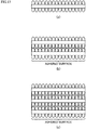
- the filmy members thus obtained were overlapped using, e.g., an adhesive as the adhesive layer, thereby obtaining three types of the transparent laminates including single layer, and two layers, three layers as well, which were overlapped respectively. That is, Fig. 6(a) shows the structure of the transparent laminate of the single layer; Fig. 6(b) shows that of the two overlapped layers; Fig. 6(c) shows that of the three overlapped layers, respectively.
- the adhesive layer is formed only at the end of the filmy member, so that the space is divided into an adhered surface and a non-adhered surface.
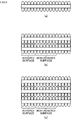
- Fig. 7(a) shows the structure of the transparent laminate of the single layer; Fig. 7(b) shows that of the two overlapped layers; Fig. 7(c) shows that of the three overlapped layers, respectively.
- the adhesive layer is formed only at the end of the filmy member, so that the space is divided into an adhered surface and a non-adhered surface.
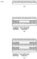
- an optical PET (polyethylene terephthalate) film available in the market was used with, e.g., adhesive serving the adhesive layer to overlap two layer and three layers, thereby obtaining three types of the transparent laminates including the single layer. That is, Fig. 8(a) shows the structure of the transparent laminate of the single layer; Fig. 8(b) shows that of the two overlapped layers; Fig. 8(c) shows that of the three overlapped layers, respectively.
- the adhesive layer is formed only at the end of the optical PET film, so that the space is divided into an adhered surface and a non-adhered surface.
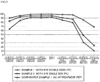
- Reflection spectrum and transmittance spectrum of the transparent laminates of Examples 1, 2 and the transparent laminate of Comparative Example 1 were measured using an ultraviolet visible light spectrophotometer (made by JASCO Corporation, Product Name V-500).
- FIG. 11 A state showing the consequences is shown in Fig. 11 .
- the transmittance of n-layer can be a transmittance of the single layer multiplied by the n-th power.
- Example 1 from Table 1 and Fig. 9 , the transmittance was very high even where three sheets are overlapped, and it turned out that the transmittance was ensured to be not less than the transmittance of the single layer of Example 2, and Comparative Example 1.
- the transmittance of the single layer in Example 2 was 95.29%, while in Example 1, at the adhered surface, two sheets overlapped have a transmittance of 99.13 % whereas three sheets overlapped have a transmittance of 98.85 %, and twenty sheets overlapped have that of 95.74%, and at the non-adhered surface, two sheets overlapped have a transmittance of 98.36 % whereas three sheets overlapped have a transmittance of 97.60 %. Those exceed the value of the single layer of Example 2, and Comparative Example 1, and it was turned out that the transmittance was maintained at the good state.
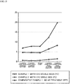
- the required eye sensed transmittance of the JIS (Japanese Industry Standard) standard (JIS T8147 protection glass) is 85% or more, but as shown in Fig. 10 , with Example 1, this required eye sensed transmittance was satisfied even in the case of 20 sheets overlapped. This means that the application range for standard products is wide.
- the reflectance as shown in Table 2 and Fig. 11 , the good result less than 4% was obtained even in the cases of two sheets overlapped and thee sheets overlapped, with the adhered surface as well as the non-adhered surface.
- Example 2 As shown in Table 1, and Figs. 9 , 10 , at the adhered surface, the transmittance equal to or more than the transmittance of the single layer of Comparative Example 1 was ensured even in the cases of the two sheets overlapped, the three sheets overlapped, and the twenty sheets overlapped. In Example 2, however, the transmittance of the non-adhered surface was dropped about 4% as one sheet increases, and influence from reflection on a surface having no fine structure can be seen more or less.
- Comparative Example 1 influences from the reflection at both boundaries of the film appeared, and the transmittance of the three sheets overlapped state was 79% on the non-adhered surface. This does not satisfy the required eye sensed transmittance 85% of the JIS standard (JIS T8147 protection glass), and it is apparent that there are adverse effects to the viewing field when the film is applied to the real shield.
- an approximate overlapping sheet number may be calculated by the transmittance of the single layer multiplied by the n-th power of the n-sheets overlapped.
- an ultraviolet curable resin having a post-cured refractive index of 1.53 was coated 4 microns with a bar coater on a surface of the polycarbonate (PC) support (having a refractive index of 1.58 and a thickness of 100 microns, and then, where a mold for the nano structure having a dot pitch of 230 nm and a dot interval between adjacent dots of 153 nm for protrusions and recesses of 220 nm, was engaged, the ultraviolet light was radiated from the PC base side to cure the resin, thereby obtaining a sheet having the nano structure on the surface.
- PC polycarbonate
- a toluene solution was added to an adhesive obtained from living radical polymerization as a main component to make a solid content 25%, and Coronate HX made of Nippon Polyurethane Industry Co., Ltd. of 20 part by weight was added as a crosslinking agent.
- the material was coated on a light-release processed PET film, dried, and sandwiched with a light-release processed polypropylene film (OPP), thereby obtaining the adhesive after stored for one week at a room temperature.
- the solid content was 25% upon adding the toluene solution.
- the main component is as follows.
- a corona processing is made on a surface to which the nano structure is not formed through the production A, and the light-release polypropylene film of the adhesive resin produced through the production B was peeled to stick the adhesive resin to the surface.
- a transparent laminate was obtained form adhering the material onto the surface of the nano structure obtained by another production A.
- Fig. 12(a) shows the structure of a transparent laminate of a single layer;
- Fig. 12(b) shows that of two sheets overlapped;
- Fig. 12(c) shows that of three sheets overlapped.
- the adhesive used for overlapping the plural layers were formed across the entire surface of the filmy members.
- Examples 4 to 8 were produced in substantially the same way as that for Example 3 except that Examples 4 to 8 have different resin composites as described above in detail.
- An adhesive was made in substantially the same way as those with the composite of Example 3 except that a resin not living polymerized but solution polymerized was used, thereby producing the transparent laminate in substantially the same way as Example 3.
- Tt The total light transmittance (Tt) was measured (JIS-K-7361) with a haze meter made of Murakami Color Research Laboratory.
- the components of a weight-average molecular weight and the components of a profile of weight-average molecular weight no more than 50,000 were measured by a liquid chromatography.
- Table 3 Initial characteristics (Transparent laminate) Nano structure characteristics after stored 10 days 40 degrees Celsius 90%RH Total light transmittance Adhesive characteristics to nano structure Appearance Total light transmittance Adhesive characteristics to nano structure Appearance % N/25 mm % N/25 mm Example 3 95.0 0.4 Normal 94.5 0.7 Normal Example 4 95.2 0.3 Normal 94.7 0.6 Normal Example 5 95.1 0.1 Normal 94.6 0.4 Normal Example 6 95.2 0.2 Normal 94.7 0.5 Normal Example 7 95.0 0.2 Normal 94.5 0.4 Normal Example 8 95.1 0.5 Normal 94.6 0.8 Normal Comparative Example 3 95.0 0.5 Normal 94.5 1.8 Irregularity
- the contents of the adhesives used for the transparent laminates of Examples 3 to 8, and the kinds of the crosslinking agents are shown in Table 4. It is to be noted that the adhesive includes the crosslinking agent or agents.
- Fig. 13(a) to Fig. 13(c) are views showing another structure of a transparent laminate, serving as an overlapped structure with adhesive layers, having filmy members having a moth-eye shape on double sides, made through the same method as that for the first example of the invention. That is, Fig. 13(a) shows the structure of the transparent laminate of the single layer; Fig. 13(b) shows that of the two overlapped layers; Fig. 13(c) shows that of the three overlapped layers, respectively.
- the adhesive used when overlapping the plural sheets are formed across the entire surface of the filmy members.
- the transparent laminate is formed by overlapping, with the adhesive, the transparent support, the base formed on at least one side with the plural structures whose pitch is equal to or less than visible light wavelength, and another base, it is desirable that the (meth)acrylic acid ester based copolymer having the weight-average molecular weight of 200,000 to 2,000,000 is used, and that the profile of weight-average molecular weight no more than 50,000 is 5% or less.
- the transparent laminate can suppress glue residues to the nano structure and changes of peeling force with the lapse of time.
- the filmy members are laminated in a plural sheet number, while the space is formed between the filmy members at a part of the area of the filmy members, and the plural filmy members are laminated with the adhesive capable of peeling at the remaining area between the filmy members.
- the low molecular weight component of the weight-average molecular weight no more than 50,000 can be 2 part by weight or less.
- the filmy member can be laminated in a plural sheet number using an ultrasound melting method or a heating melting method.
- the transparent laminate can be realized with no glue remaining and no deterioration of adhesive characteristics.
Landscapes
- Physics & Mathematics (AREA)
- General Physics & Mathematics (AREA)
- Optics & Photonics (AREA)
- Laminated Bodies (AREA)
- Helmets And Other Head Coverings (AREA)
Applications Claiming Priority (3)
| Application Number | Priority Date | Filing Date | Title |
|---|---|---|---|
| JP2013165708 | 2013-08-09 | ||
| JP2014069558A JP6493900B2 (ja) | 2013-08-09 | 2014-03-28 | 透明積層体、及びそれを用いた保護具 |
| PCT/JP2014/002980 WO2015019529A1 (ja) | 2013-08-09 | 2014-06-04 | 透明積層体、及びそれを用いた保護具 |
Publications (3)
| Publication Number | Publication Date |
|---|---|
| EP3031602A1 true EP3031602A1 (de) | 2016-06-15 |
| EP3031602A4 EP3031602A4 (de) | 2017-04-26 |
| EP3031602B1 EP3031602B1 (de) | 2020-12-30 |
Family
ID=52460893
Family Applications (1)
| Application Number | Title | Priority Date | Filing Date |
|---|---|---|---|
| EP14834273.6A Active EP3031602B1 (de) | 2013-08-09 | 2014-06-04 | Transparentes laminat und schützendes werkzeug damit |
Country Status (4)
| Country | Link |
|---|---|
| US (1) | US10000037B2 (de) |
| EP (1) | EP3031602B1 (de) |
| JP (1) | JP6493900B2 (de) |
| WO (1) | WO2015019529A1 (de) |
Cited By (2)
| Publication number | Priority date | Publication date | Assignee | Title |
|---|---|---|---|---|
| EP3878643A4 (de) * | 2018-11-08 | 2022-08-03 | Dexerials Corporation | Schichtkörper, verfahren zur herstellung eines schichtkörpers, verfahren zur herstellung eines optischen körpers und kameramodulmontagevorrichtung |
| US11708150B2 (en) | 2021-02-09 | 2023-07-25 | Safran Landing Systems Canada Inc. | Hybrid main landing gear fitting with detachable drag arm |
Families Citing this family (9)
| Publication number | Priority date | Publication date | Assignee | Title |
|---|---|---|---|---|
| JP6684046B2 (ja) * | 2014-07-30 | 2020-04-22 | デクセリアルズ株式会社 | 透明積層体 |
| US11585962B2 (en) * | 2018-10-19 | 2023-02-21 | Racing Optics, Inc. | Transparent covering having anti-reflective coatings |
| US11635622B1 (en) * | 2018-12-07 | 2023-04-25 | Meta Platforms Technologies, Llc | Nanovided spacer materials and corresponding systems and methods |
| JP7669705B2 (ja) | 2021-01-28 | 2025-04-30 | 大日本印刷株式会社 | 透明積層フィルム、保護フィルム付き透明積層フィルムおよびフェイスシールド |
| WO2022054933A1 (ja) * | 2020-09-11 | 2022-03-17 | 大日本印刷株式会社 | 透明積層フィルム、保護フィルム付き透明積層フィルムおよびフェイスシールド |
| US11307329B1 (en) | 2021-07-27 | 2022-04-19 | Racing Optics, Inc. | Low reflectance removable lens stack |
| US12140781B2 (en) | 2021-07-27 | 2024-11-12 | Laminated Film Llc | Low reflectance removable lens stack |
| JP7791771B2 (ja) | 2022-05-19 | 2025-12-24 | デクセリアルズ株式会社 | フィルム積層体、フィルム積層体の製造方法、保護具、保護具の製造方法 |
| JP2023170535A (ja) | 2022-05-19 | 2023-12-01 | デクセリアルズ株式会社 | フィルム積層体、フィルム積層体の製造方法、保護具、保護具の製造方法 |
Family Cites Families (35)
| Publication number | Priority date | Publication date | Assignee | Title |
|---|---|---|---|---|
| US2511329A (en) * | 1946-12-26 | 1950-06-13 | Craig Edward | Lens shield |
| US3904281A (en) * | 1969-12-08 | 1975-09-09 | Optical Sciences Group Inc | Flexible refracting membrane adhered to spectacle lens |
| US5002326A (en) | 1990-01-22 | 1991-03-26 | Westfield William R | Automotive windshield laminated protector |
| JP2698799B2 (ja) * | 1991-09-20 | 1998-01-19 | セイコープレシジョン株式会社 | インクジェットヘッド |
| US5502516A (en) * | 1994-03-11 | 1996-03-26 | Elterman; Warren B. | Disposable/reusable sun filter |
| US5592698A (en) | 1995-06-30 | 1997-01-14 | Woods; Marlen M. | Tear-off lens for transparent eye and face shield |
| JPH0966606A (ja) * | 1995-08-31 | 1997-03-11 | Seikosha Co Ltd | インクジェットヘッドの製造方法 |
| WO1999048339A1 (en) * | 1998-03-17 | 1999-09-23 | Seiko Epson Corporation | Substrate for patterning thin film and surface treatment thereof |
| JP3870562B2 (ja) * | 1998-07-16 | 2007-01-17 | セイコーエプソン株式会社 | パターン形成方法、およびパターン形成基板の製造方法 |
| US6461709B1 (en) * | 1998-10-28 | 2002-10-08 | 3M Innovative Properties Company | Graffiti and/or environmental protective article having removable sheets, substrates protected therewith, and a method of use |
| JP2000192322A (ja) | 1998-12-24 | 2000-07-11 | Teac Corp | ヘルメットのシールド部分の保護装置 |
| US20020159159A1 (en) * | 1999-11-24 | 2002-10-31 | Bart Wilson | Optical stack of laminated removable lenses |
| US6536045B1 (en) * | 1999-11-24 | 2003-03-25 | Racing Optics | Tear-off optical stack having peripheral seal mount |
| US8054416B2 (en) * | 2000-08-15 | 2011-11-08 | Reflexite Corporation | Light polarizer |
| JP2003222701A (ja) * | 2002-01-29 | 2003-08-08 | Seiko Epson Corp | 光学部品及びその製造方法 |
| JP4269769B2 (ja) | 2003-05-07 | 2009-05-27 | ソニー株式会社 | バッテリパック及び電子機器 |
| US7540039B2 (en) * | 2003-06-19 | 2009-06-02 | Reaux Brian K | Face and eye covering device |
| CA2602821C (en) * | 2005-03-24 | 2014-05-27 | Stryker Corporation | Personal protection system including a helmet with a fan and duct system that direct air onto the neck of the wearer |
| KR100831558B1 (ko) * | 2005-11-18 | 2008-05-21 | 주식회사 엘지화학 | 편광판용 아크릴계 점착제 조성물 |
| JP5170495B2 (ja) * | 2006-03-20 | 2013-03-27 | 日産自動車株式会社 | 反射防止微細構造及び反射防止構造体 |
| JP2010048902A (ja) | 2008-08-19 | 2010-03-04 | The Inctec Inc | 低反射透明板及びそれを用いた展示用ケース |
| CN101938899B (zh) * | 2008-12-25 | 2013-04-10 | 夏普株式会社 | 贮液槽、液中观察器具及光学膜 |
| JP5244976B2 (ja) * | 2009-08-05 | 2013-07-24 | シャープ株式会社 | 板状部材及び観察窓付き構造物 |
| JP4626721B1 (ja) * | 2009-09-02 | 2011-02-09 | ソニー株式会社 | 透明導電性電極、タッチパネル、情報入力装置、および表示装置 |
| TWI467214B (zh) * | 2009-09-02 | 2015-01-01 | Dexerials Corp | A conductive optical element, a touch panel, an information input device, a display device, a solar cell, and a conductive optical element |
| WO2011149948A1 (en) * | 2010-05-24 | 2011-12-01 | Astic Signals Defenses Llc | Transparent, biodegradable, protective screens and uses thereof |
| JP4849183B1 (ja) * | 2010-08-05 | 2012-01-11 | 大日本印刷株式会社 | 反射防止フィルム製造用金型の製造方法 |
| JP5895335B2 (ja) | 2010-10-22 | 2016-03-30 | ソニー株式会社 | 積層体、成型素子、および光学素子 |
| GB2485522B (en) * | 2010-10-11 | 2012-10-31 | Fu-Yi Hsu | Screen protective sticker structure |
| JP2012212080A (ja) * | 2011-03-31 | 2012-11-01 | Sumitomo Chemical Co Ltd | 偏光板 |
| TWI537357B (zh) * | 2011-06-11 | 2016-06-11 | Toagosei Co Ltd | Plastic film or sheet with active high-energy radiation hardening adhesive composition (b) |
| CN104483721B (zh) * | 2011-12-02 | 2016-09-07 | 夏普株式会社 | 层叠体 |
| JP2013195579A (ja) * | 2012-03-16 | 2013-09-30 | Sony Corp | 積層体およびその製造方法、透明基材、表示装置、入力装置ならびに電子機器 |
| JP3178509U (ja) * | 2012-06-26 | 2012-09-20 | 章 富岡 | 使い捨て透明フィルム付きメガネ |
| JP2014155689A (ja) * | 2013-01-17 | 2014-08-28 | Dexerials Corp | 顔面保護用光学素子 |
-
2014
- 2014-03-28 JP JP2014069558A patent/JP6493900B2/ja active Active
- 2014-06-04 US US14/910,598 patent/US10000037B2/en active Active
- 2014-06-04 EP EP14834273.6A patent/EP3031602B1/de active Active
- 2014-06-04 WO PCT/JP2014/002980 patent/WO2015019529A1/ja not_active Ceased
Non-Patent Citations (1)
| Title |
|---|
| See references of WO2015019529A1 * |
Cited By (3)
| Publication number | Priority date | Publication date | Assignee | Title |
|---|---|---|---|---|
| EP3878643A4 (de) * | 2018-11-08 | 2022-08-03 | Dexerials Corporation | Schichtkörper, verfahren zur herstellung eines schichtkörpers, verfahren zur herstellung eines optischen körpers und kameramodulmontagevorrichtung |
| US12399303B2 (en) | 2018-11-08 | 2025-08-26 | Dexerials Corporation | Laminate, method of producing laminate, method of forming optical body, and camera module-equipped device |
| US11708150B2 (en) | 2021-02-09 | 2023-07-25 | Safran Landing Systems Canada Inc. | Hybrid main landing gear fitting with detachable drag arm |
Also Published As
| Publication number | Publication date |
|---|---|
| US10000037B2 (en) | 2018-06-19 |
| JP2015057317A (ja) | 2015-03-26 |
| JP6493900B2 (ja) | 2019-04-03 |
| WO2015019529A1 (ja) | 2015-02-12 |
| EP3031602A4 (de) | 2017-04-26 |
| US20160193808A1 (en) | 2016-07-07 |
| EP3031602B1 (de) | 2020-12-30 |
Similar Documents
| Publication | Publication Date | Title |
|---|---|---|
| EP3031602B1 (de) | Transparentes laminat und schützendes werkzeug damit | |
| JP6234970B2 (ja) | 透明な粘着剤層を有する透明導電層付カバー部材 | |
| EP3165358B1 (de) | Transparente folie für gesichtsschutzschild | |
| CN108230900B (zh) | 图像显示装置 | |
| EP3141944B1 (de) | Brillenschutzvorrichtung | |
| JP6609402B2 (ja) | 光学フィルム及びその製造方法 | |
| JP2016122163A (ja) | 光学フィルム及びその製造方法 | |
| KR101840992B1 (ko) | 투명한 점착제층을 갖는 도전성 필름 적층체 | |
| KR20130099957A (ko) | 영상 표시 장치 제조 방법 | |
| JP6858912B2 (ja) | フレキシブル画像表示装置およびそれに用いる光学積層体 | |
| JP6655239B2 (ja) | 透明積層体、及びそれを用いた保護具 | |
| JPWO2014069542A1 (ja) | 積層体および表示装置 | |
| JP2013218118A (ja) | 情報表示面用の両面粘着シート,情報表示面の保護シート,及び前記両面粘着シート及び保護シートの製造方法 | |
| JP2024161034A (ja) | 反射防止フィルム積層体、それを備える物品及び反射防止フィルム積層体の製造方法 | |
| KR101798759B1 (ko) | 곡면부를 가진 휴대기기에 부착되는 보호시트 모듈, 이를 이용한 보호시트 제조방법 및 그에 의해 제조된 보호시트 | |
| JP2013195579A (ja) | 積層体およびその製造方法、透明基材、表示装置、入力装置ならびに電子機器 | |
| KR101819437B1 (ko) | 투명한 점착제층을 갖는 도전성 필름 적층체 | |
| KR20090110635A (ko) | 양면 점착 시트, 이를 이용한 표시 장치 및 그 제조 방법 | |
| KR20210084438A (ko) | 가식 부착 적층체, 광학 적층체 및 플렉서블 화상 표시 장치 | |
| JP3707263B2 (ja) | ディスプレイ用前面板 | |
| KR20220148728A (ko) | 표면 보호 필름 및 그것이 첩착된 광학 부품 | |
| KR20240032202A (ko) | 플렉시블 커버 윈도우 제조 방법 및 이에 의한 플렉시블 커버 윈도우 | |
| JP2013026326A (ja) | アース取り出し部を有する電磁波遮蔽シートの製造方法 | |
| JP2018187927A (ja) | 成形体及びそれを用いた表示装置 |
Legal Events
| Date | Code | Title | Description |
|---|---|---|---|
| PUAI | Public reference made under article 153(3) epc to a published international application that has entered the european phase |
Free format text: ORIGINAL CODE: 0009012 |
|
| 17P | Request for examination filed |
Effective date: 20160308 |
|
| AK | Designated contracting states |
Kind code of ref document: A1 Designated state(s): AL AT BE BG CH CY CZ DE DK EE ES FI FR GB GR HR HU IE IS IT LI LT LU LV MC MK MT NL NO PL PT RO RS SE SI SK SM TR |
|
| AX | Request for extension of the european patent |
Extension state: BA ME |
|
| DAX | Request for extension of the european patent (deleted) | ||
| A4 | Supplementary search report drawn up and despatched |
Effective date: 20170324 |
|
| RIC1 | Information provided on ipc code assigned before grant |
Ipc: A42B 3/22 20060101ALI20170320BHEP Ipc: B32B 7/12 20060101ALI20170320BHEP Ipc: B32B 7/06 20060101ALI20170320BHEP Ipc: B32B 3/30 20060101AFI20170320BHEP Ipc: G02B 1/118 20150101ALI20170320BHEP |
|
| RIN1 | Information on inventor provided before grant (corrected) |
Inventor name: NISHIMURA, KIMITAKA Inventor name: OHTA, EIJI Inventor name: MATSUMURA, SHINICHI Inventor name: OHKAWARA, SHIGEHISA Inventor name: YOSHIDA, EMI |
|
| STAA | Information on the status of an ep patent application or granted ep patent |
Free format text: STATUS: EXAMINATION IS IN PROGRESS |
|
| 17Q | First examination report despatched |
Effective date: 20180814 |
|
| GRAP | Despatch of communication of intention to grant a patent |
Free format text: ORIGINAL CODE: EPIDOSNIGR1 |
|
| STAA | Information on the status of an ep patent application or granted ep patent |
Free format text: STATUS: GRANT OF PATENT IS INTENDED |
|
| INTG | Intention to grant announced |
Effective date: 20200714 |
|
| GRAS | Grant fee paid |
Free format text: ORIGINAL CODE: EPIDOSNIGR3 |
|
| GRAA | (expected) grant |
Free format text: ORIGINAL CODE: 0009210 |
|
| STAA | Information on the status of an ep patent application or granted ep patent |
Free format text: STATUS: THE PATENT HAS BEEN GRANTED |
|
| AK | Designated contracting states |
Kind code of ref document: B1 Designated state(s): AL AT BE BG CH CY CZ DE DK EE ES FI FR GB GR HR HU IE IS IT LI LT LU LV MC MK MT NL NO PL PT RO RS SE SI SK SM TR |
|
| REG | Reference to a national code |
Ref country code: GB Ref legal event code: FG4D |
|
| REG | Reference to a national code |
Ref country code: AT Ref legal event code: REF Ref document number: 1349512 Country of ref document: AT Kind code of ref document: T Effective date: 20210115 |
|
| REG | Reference to a national code |
Ref country code: DE Ref legal event code: R096 Ref document number: 602014073851 Country of ref document: DE |
|
| REG | Reference to a national code |
Ref country code: IE Ref legal event code: FG4D |
|
| REG | Reference to a national code |
Ref country code: NL Ref legal event code: FP |
|
| PG25 | Lapsed in a contracting state [announced via postgrant information from national office to epo] |
Ref country code: RS Free format text: LAPSE BECAUSE OF FAILURE TO SUBMIT A TRANSLATION OF THE DESCRIPTION OR TO PAY THE FEE WITHIN THE PRESCRIBED TIME-LIMIT Effective date: 20201230 Ref country code: FI Free format text: LAPSE BECAUSE OF FAILURE TO SUBMIT A TRANSLATION OF THE DESCRIPTION OR TO PAY THE FEE WITHIN THE PRESCRIBED TIME-LIMIT Effective date: 20201230 Ref country code: NO Free format text: LAPSE BECAUSE OF FAILURE TO SUBMIT A TRANSLATION OF THE DESCRIPTION OR TO PAY THE FEE WITHIN THE PRESCRIBED TIME-LIMIT Effective date: 20210330 Ref country code: GR Free format text: LAPSE BECAUSE OF FAILURE TO SUBMIT A TRANSLATION OF THE DESCRIPTION OR TO PAY THE FEE WITHIN THE PRESCRIBED TIME-LIMIT Effective date: 20210331 |
|
| REG | Reference to a national code |
Ref country code: AT Ref legal event code: MK05 Ref document number: 1349512 Country of ref document: AT Kind code of ref document: T Effective date: 20201230 |
|
| PG25 | Lapsed in a contracting state [announced via postgrant information from national office to epo] |
Ref country code: SE Free format text: LAPSE BECAUSE OF FAILURE TO SUBMIT A TRANSLATION OF THE DESCRIPTION OR TO PAY THE FEE WITHIN THE PRESCRIBED TIME-LIMIT Effective date: 20201230 Ref country code: LV Free format text: LAPSE BECAUSE OF FAILURE TO SUBMIT A TRANSLATION OF THE DESCRIPTION OR TO PAY THE FEE WITHIN THE PRESCRIBED TIME-LIMIT Effective date: 20201230 Ref country code: BG Free format text: LAPSE BECAUSE OF FAILURE TO SUBMIT A TRANSLATION OF THE DESCRIPTION OR TO PAY THE FEE WITHIN THE PRESCRIBED TIME-LIMIT Effective date: 20210330 |
|
| PG25 | Lapsed in a contracting state [announced via postgrant information from national office to epo] |
Ref country code: HR Free format text: LAPSE BECAUSE OF FAILURE TO SUBMIT A TRANSLATION OF THE DESCRIPTION OR TO PAY THE FEE WITHIN THE PRESCRIBED TIME-LIMIT Effective date: 20201230 |
|
| REG | Reference to a national code |
Ref country code: LT Ref legal event code: MG9D |
|
| PG25 | Lapsed in a contracting state [announced via postgrant information from national office to epo] |
Ref country code: PT Free format text: LAPSE BECAUSE OF FAILURE TO SUBMIT A TRANSLATION OF THE DESCRIPTION OR TO PAY THE FEE WITHIN THE PRESCRIBED TIME-LIMIT Effective date: 20210430 Ref country code: RO Free format text: LAPSE BECAUSE OF FAILURE TO SUBMIT A TRANSLATION OF THE DESCRIPTION OR TO PAY THE FEE WITHIN THE PRESCRIBED TIME-LIMIT Effective date: 20201230 Ref country code: SK Free format text: LAPSE BECAUSE OF FAILURE TO SUBMIT A TRANSLATION OF THE DESCRIPTION OR TO PAY THE FEE WITHIN THE PRESCRIBED TIME-LIMIT Effective date: 20201230 Ref country code: LT Free format text: LAPSE BECAUSE OF FAILURE TO SUBMIT A TRANSLATION OF THE DESCRIPTION OR TO PAY THE FEE WITHIN THE PRESCRIBED TIME-LIMIT Effective date: 20201230 Ref country code: EE Free format text: LAPSE BECAUSE OF FAILURE TO SUBMIT A TRANSLATION OF THE DESCRIPTION OR TO PAY THE FEE WITHIN THE PRESCRIBED TIME-LIMIT Effective date: 20201230 Ref country code: CZ Free format text: LAPSE BECAUSE OF FAILURE TO SUBMIT A TRANSLATION OF THE DESCRIPTION OR TO PAY THE FEE WITHIN THE PRESCRIBED TIME-LIMIT Effective date: 20201230 |
|
| PG25 | Lapsed in a contracting state [announced via postgrant information from national office to epo] |
Ref country code: AT Free format text: LAPSE BECAUSE OF FAILURE TO SUBMIT A TRANSLATION OF THE DESCRIPTION OR TO PAY THE FEE WITHIN THE PRESCRIBED TIME-LIMIT Effective date: 20201230 Ref country code: PL Free format text: LAPSE BECAUSE OF FAILURE TO SUBMIT A TRANSLATION OF THE DESCRIPTION OR TO PAY THE FEE WITHIN THE PRESCRIBED TIME-LIMIT Effective date: 20201230 |
|
| PG25 | Lapsed in a contracting state [announced via postgrant information from national office to epo] |
Ref country code: IS Free format text: LAPSE BECAUSE OF FAILURE TO SUBMIT A TRANSLATION OF THE DESCRIPTION OR TO PAY THE FEE WITHIN THE PRESCRIBED TIME-LIMIT Effective date: 20210430 |
|
| REG | Reference to a national code |
Ref country code: DE Ref legal event code: R097 Ref document number: 602014073851 Country of ref document: DE |
|
| PG25 | Lapsed in a contracting state [announced via postgrant information from national office to epo] |
Ref country code: AL Free format text: LAPSE BECAUSE OF FAILURE TO SUBMIT A TRANSLATION OF THE DESCRIPTION OR TO PAY THE FEE WITHIN THE PRESCRIBED TIME-LIMIT Effective date: 20201230 |
|
| PLBE | No opposition filed within time limit |
Free format text: ORIGINAL CODE: 0009261 |
|
| STAA | Information on the status of an ep patent application or granted ep patent |
Free format text: STATUS: NO OPPOSITION FILED WITHIN TIME LIMIT |
|
| PG25 | Lapsed in a contracting state [announced via postgrant information from national office to epo] |
Ref country code: ES Free format text: LAPSE BECAUSE OF FAILURE TO SUBMIT A TRANSLATION OF THE DESCRIPTION OR TO PAY THE FEE WITHIN THE PRESCRIBED TIME-LIMIT Effective date: 20201230 Ref country code: DK Free format text: LAPSE BECAUSE OF FAILURE TO SUBMIT A TRANSLATION OF THE DESCRIPTION OR TO PAY THE FEE WITHIN THE PRESCRIBED TIME-LIMIT Effective date: 20201230 |
|
| 26N | No opposition filed |
Effective date: 20211001 |
|
| PG25 | Lapsed in a contracting state [announced via postgrant information from national office to epo] |
Ref country code: MC Free format text: LAPSE BECAUSE OF FAILURE TO SUBMIT A TRANSLATION OF THE DESCRIPTION OR TO PAY THE FEE WITHIN THE PRESCRIBED TIME-LIMIT Effective date: 20201230 |
|
| REG | Reference to a national code |
Ref country code: CH Ref legal event code: PL |
|
| PG25 | Lapsed in a contracting state [announced via postgrant information from national office to epo] |
Ref country code: SI Free format text: LAPSE BECAUSE OF FAILURE TO SUBMIT A TRANSLATION OF THE DESCRIPTION OR TO PAY THE FEE WITHIN THE PRESCRIBED TIME-LIMIT Effective date: 20201230 |
|
| REG | Reference to a national code |
Ref country code: BE Ref legal event code: MM Effective date: 20210630 |
|
| PG25 | Lapsed in a contracting state [announced via postgrant information from national office to epo] |
Ref country code: LU Free format text: LAPSE BECAUSE OF NON-PAYMENT OF DUE FEES Effective date: 20210604 |
|
| PG25 | Lapsed in a contracting state [announced via postgrant information from national office to epo] |
Ref country code: LI Free format text: LAPSE BECAUSE OF NON-PAYMENT OF DUE FEES Effective date: 20210630 Ref country code: IE Free format text: LAPSE BECAUSE OF NON-PAYMENT OF DUE FEES Effective date: 20210604 Ref country code: CH Free format text: LAPSE BECAUSE OF NON-PAYMENT OF DUE FEES Effective date: 20210630 |
|
| PG25 | Lapsed in a contracting state [announced via postgrant information from national office to epo] |
Ref country code: IS Free format text: LAPSE BECAUSE OF FAILURE TO SUBMIT A TRANSLATION OF THE DESCRIPTION OR TO PAY THE FEE WITHIN THE PRESCRIBED TIME-LIMIT Effective date: 20210430 |
|
| PG25 | Lapsed in a contracting state [announced via postgrant information from national office to epo] |
Ref country code: BE Free format text: LAPSE BECAUSE OF NON-PAYMENT OF DUE FEES Effective date: 20210630 |
|
| PG25 | Lapsed in a contracting state [announced via postgrant information from national office to epo] |
Ref country code: HU Free format text: LAPSE BECAUSE OF FAILURE TO SUBMIT A TRANSLATION OF THE DESCRIPTION OR TO PAY THE FEE WITHIN THE PRESCRIBED TIME-LIMIT; INVALID AB INITIO Effective date: 20140604 |
|
| PG25 | Lapsed in a contracting state [announced via postgrant information from national office to epo] |
Ref country code: CY Free format text: LAPSE BECAUSE OF FAILURE TO SUBMIT A TRANSLATION OF THE DESCRIPTION OR TO PAY THE FEE WITHIN THE PRESCRIBED TIME-LIMIT Effective date: 20201230 |
|
| PG25 | Lapsed in a contracting state [announced via postgrant information from national office to epo] |
Ref country code: SM Free format text: LAPSE BECAUSE OF FAILURE TO SUBMIT A TRANSLATION OF THE DESCRIPTION OR TO PAY THE FEE WITHIN THE PRESCRIBED TIME-LIMIT Effective date: 20201230 |
|
| PG25 | Lapsed in a contracting state [announced via postgrant information from national office to epo] |
Ref country code: MK Free format text: LAPSE BECAUSE OF FAILURE TO SUBMIT A TRANSLATION OF THE DESCRIPTION OR TO PAY THE FEE WITHIN THE PRESCRIBED TIME-LIMIT Effective date: 20201230 |
|
| PG25 | Lapsed in a contracting state [announced via postgrant information from national office to epo] |
Ref country code: TR Free format text: LAPSE BECAUSE OF FAILURE TO SUBMIT A TRANSLATION OF THE DESCRIPTION OR TO PAY THE FEE WITHIN THE PRESCRIBED TIME-LIMIT Effective date: 20201230 |
|
| PG25 | Lapsed in a contracting state [announced via postgrant information from national office to epo] |
Ref country code: MT Free format text: LAPSE BECAUSE OF FAILURE TO SUBMIT A TRANSLATION OF THE DESCRIPTION OR TO PAY THE FEE WITHIN THE PRESCRIBED TIME-LIMIT Effective date: 20201230 |
|
| PGFP | Annual fee paid to national office [announced via postgrant information from national office to epo] |
Ref country code: NL Payment date: 20250516 Year of fee payment: 12 |
|
| PGFP | Annual fee paid to national office [announced via postgrant information from national office to epo] |
Ref country code: DE Payment date: 20250429 Year of fee payment: 12 |
|
| PGFP | Annual fee paid to national office [announced via postgrant information from national office to epo] |
Ref country code: GB Payment date: 20250501 Year of fee payment: 12 |
|
| PGFP | Annual fee paid to national office [announced via postgrant information from national office to epo] |
Ref country code: IT Payment date: 20250522 Year of fee payment: 12 |
|
| PGFP | Annual fee paid to national office [announced via postgrant information from national office to epo] |
Ref country code: FR Payment date: 20250508 Year of fee payment: 12 |