EP3030210B1 - Vibrationstherapievorrichtung mit auflageflächen und einer lineare lateralschwingungen erzeugenden schwingungserzeugungseinrichtung - Google Patents
Vibrationstherapievorrichtung mit auflageflächen und einer lineare lateralschwingungen erzeugenden schwingungserzeugungseinrichtung Download PDFInfo
- Publication number
- EP3030210B1 EP3030210B1 EP14749775.4A EP14749775A EP3030210B1 EP 3030210 B1 EP3030210 B1 EP 3030210B1 EP 14749775 A EP14749775 A EP 14749775A EP 3030210 B1 EP3030210 B1 EP 3030210B1
- Authority
- EP
- European Patent Office
- Prior art keywords
- support surface
- therapy device
- vibration therapy
- vibration
- oscillation
- Prior art date
- Legal status (The legal status is an assumption and is not a legal conclusion. Google has not performed a legal analysis and makes no representation as to the accuracy of the status listed.)
- Active
Links
Images


Classifications
-
- A—HUMAN NECESSITIES
- A61—MEDICAL OR VETERINARY SCIENCE; HYGIENE
- A61H—PHYSICAL THERAPY APPARATUS, e.g. DEVICES FOR LOCATING OR STIMULATING REFLEX POINTS IN THE BODY; ARTIFICIAL RESPIRATION; MASSAGE; BATHING DEVICES FOR SPECIAL THERAPEUTIC OR HYGIENIC PURPOSES OR SPECIFIC PARTS OF THE BODY
- A61H1/00—Apparatus for passive exercising; Vibrating apparatus; Chiropractic devices, e.g. body impacting devices, external devices for briefly extending or aligning unbroken bones
- A61H1/005—Moveable platforms, e.g. vibrating or oscillating platforms for standing, sitting, laying or leaning
-
- A—HUMAN NECESSITIES
- A61—MEDICAL OR VETERINARY SCIENCE; HYGIENE
- A61H—PHYSICAL THERAPY APPARATUS, e.g. DEVICES FOR LOCATING OR STIMULATING REFLEX POINTS IN THE BODY; ARTIFICIAL RESPIRATION; MASSAGE; BATHING DEVICES FOR SPECIAL THERAPEUTIC OR HYGIENIC PURPOSES OR SPECIFIC PARTS OF THE BODY
- A61H1/00—Apparatus for passive exercising; Vibrating apparatus; Chiropractic devices, e.g. body impacting devices, external devices for briefly extending or aligning unbroken bones
- A61H1/02—Stretching or bending or torsioning apparatus for exercising
- A61H1/0237—Stretching or bending or torsioning apparatus for exercising for the lower limbs
- A61H1/0244—Hip
-
- A—HUMAN NECESSITIES
- A61—MEDICAL OR VETERINARY SCIENCE; HYGIENE
- A61H—PHYSICAL THERAPY APPARATUS, e.g. DEVICES FOR LOCATING OR STIMULATING REFLEX POINTS IN THE BODY; ARTIFICIAL RESPIRATION; MASSAGE; BATHING DEVICES FOR SPECIAL THERAPEUTIC OR HYGIENIC PURPOSES OR SPECIFIC PARTS OF THE BODY
- A61H1/00—Apparatus for passive exercising; Vibrating apparatus; Chiropractic devices, e.g. body impacting devices, external devices for briefly extending or aligning unbroken bones
- A61H1/02—Stretching or bending or torsioning apparatus for exercising
- A61H1/0292—Stretching or bending or torsioning apparatus for exercising for the spinal column
-
- A—HUMAN NECESSITIES
- A61—MEDICAL OR VETERINARY SCIENCE; HYGIENE
- A61H—PHYSICAL THERAPY APPARATUS, e.g. DEVICES FOR LOCATING OR STIMULATING REFLEX POINTS IN THE BODY; ARTIFICIAL RESPIRATION; MASSAGE; BATHING DEVICES FOR SPECIAL THERAPEUTIC OR HYGIENIC PURPOSES OR SPECIFIC PARTS OF THE BODY
- A61H1/00—Apparatus for passive exercising; Vibrating apparatus; Chiropractic devices, e.g. body impacting devices, external devices for briefly extending or aligning unbroken bones
- A61H1/02—Stretching or bending or torsioning apparatus for exercising
- A61H1/0292—Stretching or bending or torsioning apparatus for exercising for the spinal column
- A61H1/0296—Neck
-
- A—HUMAN NECESSITIES
- A61—MEDICAL OR VETERINARY SCIENCE; HYGIENE
- A61H—PHYSICAL THERAPY APPARATUS, e.g. DEVICES FOR LOCATING OR STIMULATING REFLEX POINTS IN THE BODY; ARTIFICIAL RESPIRATION; MASSAGE; BATHING DEVICES FOR SPECIAL THERAPEUTIC OR HYGIENIC PURPOSES OR SPECIFIC PARTS OF THE BODY
- A61H23/00—Percussion or vibration massage, e.g. using supersonic vibration; Suction-vibration massage; Massage with moving diaphragms
- A61H23/02—Percussion or vibration massage, e.g. using supersonic vibration; Suction-vibration massage; Massage with moving diaphragms with electric or magnetic drive
- A61H23/0254—Percussion or vibration massage, e.g. using supersonic vibration; Suction-vibration massage; Massage with moving diaphragms with electric or magnetic drive with rotary motor
- A61H23/0263—Percussion or vibration massage, e.g. using supersonic vibration; Suction-vibration massage; Massage with moving diaphragms with electric or magnetic drive with rotary motor using rotating unbalanced masses
-
- A—HUMAN NECESSITIES
- A61—MEDICAL OR VETERINARY SCIENCE; HYGIENE
- A61H—PHYSICAL THERAPY APPARATUS, e.g. DEVICES FOR LOCATING OR STIMULATING REFLEX POINTS IN THE BODY; ARTIFICIAL RESPIRATION; MASSAGE; BATHING DEVICES FOR SPECIAL THERAPEUTIC OR HYGIENIC PURPOSES OR SPECIFIC PARTS OF THE BODY
- A61H2201/00—Characteristics of apparatus not provided for in the preceding codes
- A61H2201/01—Constructive details
- A61H2201/0107—Constructive details modular
-
- A—HUMAN NECESSITIES
- A61—MEDICAL OR VETERINARY SCIENCE; HYGIENE
- A61H—PHYSICAL THERAPY APPARATUS, e.g. DEVICES FOR LOCATING OR STIMULATING REFLEX POINTS IN THE BODY; ARTIFICIAL RESPIRATION; MASSAGE; BATHING DEVICES FOR SPECIAL THERAPEUTIC OR HYGIENIC PURPOSES OR SPECIFIC PARTS OF THE BODY
- A61H2201/00—Characteristics of apparatus not provided for in the preceding codes
- A61H2201/01—Constructive details
- A61H2201/0119—Support for the device
- A61H2201/0138—Support for the device incorporated in furniture
- A61H2201/0142—Beds
-
- A—HUMAN NECESSITIES
- A61—MEDICAL OR VETERINARY SCIENCE; HYGIENE
- A61H—PHYSICAL THERAPY APPARATUS, e.g. DEVICES FOR LOCATING OR STIMULATING REFLEX POINTS IN THE BODY; ARTIFICIAL RESPIRATION; MASSAGE; BATHING DEVICES FOR SPECIAL THERAPEUTIC OR HYGIENIC PURPOSES OR SPECIFIC PARTS OF THE BODY
- A61H2201/00—Characteristics of apparatus not provided for in the preceding codes
- A61H2201/14—Special force transmission means, i.e. between the driving means and the interface with the user
- A61H2201/1436—Special crank assembly
-
- A—HUMAN NECESSITIES
- A61—MEDICAL OR VETERINARY SCIENCE; HYGIENE
- A61H—PHYSICAL THERAPY APPARATUS, e.g. DEVICES FOR LOCATING OR STIMULATING REFLEX POINTS IN THE BODY; ARTIFICIAL RESPIRATION; MASSAGE; BATHING DEVICES FOR SPECIAL THERAPEUTIC OR HYGIENIC PURPOSES OR SPECIFIC PARTS OF THE BODY
- A61H2201/00—Characteristics of apparatus not provided for in the preceding codes
- A61H2201/14—Special force transmission means, i.e. between the driving means and the interface with the user
- A61H2201/1481—Special movement conversion means
- A61H2201/149—Special movement conversion means rotation-linear or vice versa
-
- A—HUMAN NECESSITIES
- A61—MEDICAL OR VETERINARY SCIENCE; HYGIENE
- A61H—PHYSICAL THERAPY APPARATUS, e.g. DEVICES FOR LOCATING OR STIMULATING REFLEX POINTS IN THE BODY; ARTIFICIAL RESPIRATION; MASSAGE; BATHING DEVICES FOR SPECIAL THERAPEUTIC OR HYGIENIC PURPOSES OR SPECIFIC PARTS OF THE BODY
- A61H2201/00—Characteristics of apparatus not provided for in the preceding codes
- A61H2201/16—Physical interface with patient
- A61H2201/1602—Physical interface with patient kind of interface, e.g. head rest, knee support or lumbar support
- A61H2201/1604—Head
-
- A—HUMAN NECESSITIES
- A61—MEDICAL OR VETERINARY SCIENCE; HYGIENE
- A61H—PHYSICAL THERAPY APPARATUS, e.g. DEVICES FOR LOCATING OR STIMULATING REFLEX POINTS IN THE BODY; ARTIFICIAL RESPIRATION; MASSAGE; BATHING DEVICES FOR SPECIAL THERAPEUTIC OR HYGIENIC PURPOSES OR SPECIFIC PARTS OF THE BODY
- A61H2201/00—Characteristics of apparatus not provided for in the preceding codes
- A61H2201/16—Physical interface with patient
- A61H2201/1602—Physical interface with patient kind of interface, e.g. head rest, knee support or lumbar support
- A61H2201/1623—Back
-
- A—HUMAN NECESSITIES
- A61—MEDICAL OR VETERINARY SCIENCE; HYGIENE
- A61H—PHYSICAL THERAPY APPARATUS, e.g. DEVICES FOR LOCATING OR STIMULATING REFLEX POINTS IN THE BODY; ARTIFICIAL RESPIRATION; MASSAGE; BATHING DEVICES FOR SPECIAL THERAPEUTIC OR HYGIENIC PURPOSES OR SPECIFIC PARTS OF THE BODY
- A61H2201/00—Characteristics of apparatus not provided for in the preceding codes
- A61H2201/16—Physical interface with patient
- A61H2201/1602—Physical interface with patient kind of interface, e.g. head rest, knee support or lumbar support
- A61H2201/1628—Pelvis
-
- A—HUMAN NECESSITIES
- A61—MEDICAL OR VETERINARY SCIENCE; HYGIENE
- A61H—PHYSICAL THERAPY APPARATUS, e.g. DEVICES FOR LOCATING OR STIMULATING REFLEX POINTS IN THE BODY; ARTIFICIAL RESPIRATION; MASSAGE; BATHING DEVICES FOR SPECIAL THERAPEUTIC OR HYGIENIC PURPOSES OR SPECIFIC PARTS OF THE BODY
- A61H2201/00—Characteristics of apparatus not provided for in the preceding codes
- A61H2201/16—Physical interface with patient
- A61H2201/1602—Physical interface with patient kind of interface, e.g. head rest, knee support or lumbar support
- A61H2201/164—Feet or leg, e.g. pedal
-
- A—HUMAN NECESSITIES
- A61—MEDICAL OR VETERINARY SCIENCE; HYGIENE
- A61H—PHYSICAL THERAPY APPARATUS, e.g. DEVICES FOR LOCATING OR STIMULATING REFLEX POINTS IN THE BODY; ARTIFICIAL RESPIRATION; MASSAGE; BATHING DEVICES FOR SPECIAL THERAPEUTIC OR HYGIENIC PURPOSES OR SPECIFIC PARTS OF THE BODY
- A61H2201/00—Characteristics of apparatus not provided for in the preceding codes
- A61H2201/16—Physical interface with patient
- A61H2201/1657—Movement of interface, i.e. force application means
- A61H2201/1664—Movement of interface, i.e. force application means linear
-
- A—HUMAN NECESSITIES
- A61—MEDICAL OR VETERINARY SCIENCE; HYGIENE
- A61H—PHYSICAL THERAPY APPARATUS, e.g. DEVICES FOR LOCATING OR STIMULATING REFLEX POINTS IN THE BODY; ARTIFICIAL RESPIRATION; MASSAGE; BATHING DEVICES FOR SPECIAL THERAPEUTIC OR HYGIENIC PURPOSES OR SPECIFIC PARTS OF THE BODY
- A61H2203/00—Additional characteristics concerning the patient
- A61H2203/04—Position of the patient
- A61H2203/0443—Position of the patient substantially horizontal
- A61H2203/0456—Supine
Definitions
- the invention relates to a vibration therapy device with a lying surface for a human body which is arranged along a longitudinal axis and which comprises a plurality of supporting surfaces and is at least partially designed as a vibrating support, a trunk module which supports a trunk supporting surface, a leg module which supports a lower leg supporting surface, and a vibration generating device.
- a vibration therapy device is from the EP 0 267 546 A2 known.
- Vibration therapy devices of the type mentioned have been known for a long time. They were originally only used for vibration massage, but are nowadays used more and more for the treatment of disorders or diseases of the musculoskeletal system and the bone skeleton. For this, combines the from the already mentioned EP 0 267 546 A2 known device a circular vibration of a support surface in the support plane with a perpendicular up and down vibration of the support surface. Both vibrations are positively coupled.
- a very similar vibration therapy device is from the DE 200 20 607 U1 known.
- a device for promoting sleep in the form of a bed in which a mattress rests on a spring arrangement.
- the spring arrangement has a frame which can be set into lateral vibrations by means of a vibration excitation device.
- the invention has for its object to provide an improved vibration therapy device that enables a more effective treatment and is particularly suitable for the treatment of the spine, pelvis and lower extremities than known vibration therapy devices.
- Conventional vibration therapy devices generate vibrations in the plane of the lying surface, which although they have lateral, ie transverse to the longitudinal axis of the lying surface, vibration components, but which also contain many non-lateral vibration components, including even those that are directed in the direction of the longitudinal axis of the lying surface.
- the invention is based on the finding that non-lateral vibrations can reduce the success of a treatment and can even have a counterproductive effect in that they Constant compression and extension of certain areas, such as the intervertebral discs, may exacerbate existing complaints.
- Such negative side effects do not occur with the linear lateral vibrations generated by the vibration generating device of the vibration therapy device according to the invention transversely to the longitudinal axis of the lying surface and in the plane of the lying surface.
- linear lateral vibrations are much better suited to loosening the spine and the pelvic area than the vibrations previously used.
- the term "linear lateral vibrations” here means vibrations which are directed exclusively or at least essentially laterally in the plane of the lying surface and which have no or only a negligible proportion of other directed vibrations in the plane of the lying surface. A possible slight up and down movement of the lying surface perpendicular to the linear lateral oscillation is possible and does not affect the desired treatment success.
- the vibration generation device has a plurality of vibration drives for generating lateral vibrations, in particular at least one vibration drive for the trunk module and at least one vibration drive for the leg module.
- the trunk and lower extremities can be treated separately and, above all, more specifically.
- Separate vibratory drives for the trunk module and the leg module also enable more effective vibration combinations for whole-body treatment, for example by swinging the lower leg support surface in the opposite direction to the trunk support surface and, if desired, with a different amplitude.
- the trunk support surface is subdivided into an upper body support surface and a pelvic support surface, and the upper body support surface and the pelvic support surface are decoupled from one another in terms of vibration technology. It is thus possible according to the invention to generate a desired vibration only between the shoulder and the pelvis, for example. Such vibrations are particularly suitable for spinal therapy, for example, because they lead to a lateral deflection of the spine that loosens the spine without applying compression or extension loads.
- the aforementioned vibrations can already be generated if a vibratory drive for generating lateral vibrations is present either for the upper body support surface or for the pelvic support surface, it is particularly advantageous if the vibration generating device each has an oscillation drive Lateral vibration generation for the upper body support surface and the pelvic support surface has.
- the device according to the invention is preferably designed in such a way that the amplitude and / or the frequency of each oscillating drive can be adjusted.
- a linear motor for example, or a drive motor with an eccentric, the eccentric movement of which is converted into the desired lateral oscillation, can be used as the oscillating drive for generating the linear lateral vibrations provided according to the invention.
- the vibration generating device for, for example, the lower leg support surface is designed such that a first vibratory drive for generating lateral vibrations with a small amplitude and a second vibratory drive for generating lateral vibrations with a significantly greater amplitude is provided.
- the first vibratory drive can have a drive motor with an eccentric and the second vibratory drive can have a linear motor.
- the second oscillating drive can also comprise a drive motor with an eccentric.
- the first and the second vibratory drive can act on the same support surface, for example the lower leg support surface, they are connected via a freewheel to the corresponding support surface, which allows an optional coupling of the first vibratory drive or the second vibratory drive to the support surface, while the other vibratory drive then is decoupled by the freewheel.
- the first vibratory drive is used to generate lateral vibrations with an amplitude in the range from 1 to 4 mm and the second vibratory drive is used to generate lateral vibrations with an amplitude in the range from 20 to 30 mm.
- Lateral vibrations with a larger amplitude, for example in the specified range of 20 to 30 mm are particularly suitable for treatments in which the legs are in an angled position. Often the lower legs are raised compared to the pelvis.
- Each vibratory drive can be designed as an exchangeable module, so that one and the same vibratory drive in a vibration therapy device according to the invention can optionally set the trunk support surface or the lower leg support surface in linear lateral vibrations by being in the relevant module Commitment comes.
- a vibration drive module can also be used at different positions within a module - for example the fuselage module.
- Such a vibratory drive module can be designed to be pluggable for easy interchangeability.
- a vibration therapy device contains a plurality of vibration drives, these are advantageously designed such that each vibration drive assigned to a support surface, which is not used for a specific use of the vibration therapy device, does not hinder a lateral vibration of this support surface. In this way, a bearing surface that is not directly excited to lateral vibrations can also follow a body vibration that results from a lateral vibration excitation elsewhere.
- the vibration therapy device can also have contact surfaces without a vibratory drive. These contact surfaces are preferably also designed in such a way that they can vibrate freely laterally in order to be able to follow body vibrations which result from a lateral vibration excitation at another point.
- the trunk module and the leg module can be adjusted and / or tilted independently of one another in order to set a comfortable and at the same time optimal therapy-effective position of the human body to be treated.
- a head support surface is preferably provided, which can be adjusted in all directions for optimal adaptation to the patient.
- the upper body support surface and / or the pelvic support surface and / or the lower leg support surface are each part of a rocking rocker, on which the oscillating drive acts to generate the lateral vibrations.
- a rocker is, for example, well suited to interact with an oscillating drive in the form of an eccentric drive, which can be formed, for example, by the drive motor with eccentric mentioned above.
- the upper body support surface is and / or the pelvic support surface and / or the lower leg support surface are mounted elastically with respect to the element which is set into linear lateral vibrations by the oscillating drive.
- this element can be a rocker.
- the elastic support of the respective support surface makes it possible to introduce further vibrations directly into the support surface, for example vibrations which support the desired treatment success through their massage effect.
- preferred embodiments of the vibration therapy device each have an unbalance motor which acts directly on the upper body support surface and / or the pelvic support surface and / or the lower leg support surface. This unbalance motor or these unbalance motors can be switched on as required and thus make it possible to apply the additional vibrations together with the linear lateral vibrations or also without them. In the latter case, the vibration therapy device can be used as a pure vibration massage device.
- the Figures 1 and 2 show a vibration therapy device generally designated 10 from the side ( Fig. 1 ) and from above ( Fig. 2 ).
- the device 10 has one Lying surface 12 for a human body, which is arranged along a longitudinal axis A and comprises a plurality of contact surfaces 14, 16.
- a trunk support surface 14 for the upper body and the pelvis is supported by a trunk module 18, while a leg module 20 supports a lower leg support surface 16.
- a headrest 22 with a head support surface 24, which is adjustable for adaptation, is connected to the fuselage module 18.
- the trunk module 18 and the leg module 20 are fastened on a common base 26 which supports the entire device 10. Both the trunk module 18 and the leg module 20 can be adjusted in height by means of an associated lifting device 28 or 30, as indicated by double arrows. The height of the leg module 20 can be adjusted relative to the trunk module 18 to such an extent that therapy with angled legs is possible (not shown). By means of assigned tilting devices 32, 34, both the trunk module 18 and the leg module 20 can also be tilted downwards and upwards in order to achieve an optimal lying position of the human body for a given therapy.
- the body support surface 14 is clearly divided into an upper body support surface 36 and a pelvic support surface 38.
- the device 10 is equipped with a vibration generating device which can apply linear lateral vibrations to the lying surface 12.
- linear lateral vibrations are meant those vibrations which run in the plane of the lying surface 12 or in the plane of the bearing surfaces 16, 36 and 38 transversely to the longitudinal axis A of the lying surface 12 or each bearing surface 16, 36 and 38.
- the fuselage module 18 in the exemplary embodiment shown is provided with at least two oscillating drives, one of which acts on the upper body support surface 36 and another on the pelvic support surface 38.
- the leg module 20 is provided with at least one oscillating drive, which acts on the lower leg support surface 16.
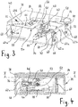
- the basic structure of such a vibratory drive can be the same and is described below together with its function using the 3 to 5 explained in more detail.
- a vibratory drive 40 for generating linear lateral vibrations is shown using the example of the vibratory drive which acts on the pelvic support surface 38.
- the heart of the oscillating drive 40 is a motor 42, the Output shaft 44 drives an eccentric 46.
- the eccentric 46 is in a longitudinal slot-like guide 48 of a bell crank 50 (see in particular Fig. 4 ) arranged, which has an axis of rotation 52 and above the axis of rotation 52 at 53 with an oscillating rocker 54 in an articulated connection.
- the rocker rocker 54 has a backbone 56 arranged transversely to the longitudinal axis A, from the ends of which two arms 58 each extend in the longitudinal direction on both sides.
- the backbone 56 and the four arms 58 are located in one and the same plane parallel to and somewhat below the pelvic support surface 38.
- Each two arms 58 extending from one side of the backbone 56 end in a side cheek 60a, 60b, which extends at right angles downward from the plane of the arms 58.
- Each side cheek 60a, 60b has two feet 62a, 62b and 64a, 64b, the free end of which is connected in an articulated manner to one end of an oscillating bracket 68 by means of an axis 66 in each case.
- the other end of each swing bracket 68 is rotatably supported by a further axis 70 in a side wall 72 of a housing 74, which receives the entire swing drive 40 and is accommodated in the fuselage module 18.
- the deflection lever 50 As soon as the motor 42 sets the eccentric 46 in rotation, the deflection lever 50 is continuously raised and lowered due to the eccentric 46 rotating in its guide 48. Because the axis of rotation 52 of the deflection lever 50 is laterally offset with respect to the eccentric 46, the deflection lever 50 carries out an oscillating movement about the axis of rotation 52, which is transmitted to the rocker rocker 54 via the articulation point 53 above the axis of rotation 52 and thereby in an essentially linear manner Lateral movement is converted.
- the rocker rocker 54 which is movably mounted to and fro in the housing 74 by means of the rocker brackets 68, thus swings back and forth transversely to the longitudinal axis A in accordance with the speed of the motor 42.
- the lateral oscillation is exactly linear in the plan view of the respective contact surface, however, the rocking rocker 54 is raised and lowered slightly in the course of the oscillating movement, which, however, does not interfere in practical use.
- the pelvic support surface 38 is connected to the rocker rocker 54 by connecting elements 76 and therefore follows its rocking movement.
- the motor 42 is mounted on a linear guide 78, by means of which it runs transversely to the longitudinal axis A. is displaceable in a range which is predetermined by the length of the longitudinal slot-like guide 48 in the bell crank 50. Due to the change in the translation of the deflection lever 50 when the motor 42 is displaced by means of the linear guide 78, the oscillation path of the oscillation rocker 54 also changes and thus the amplitude of the lateral oscillation.
- another motor 80 is used to move the motor 42, which can move the linear guide 78 back and forth by means of a worm.
- the connecting elements 76 are designed as elastic elements, as a result of which the pelvic support surface 38 is somewhat decoupled from the rocker rocker 54 in order to be able to apply a massage vibration to the pelvic support surface 38 in addition to the lateral oscillation.
- an unbalance motor 82 is screwed directly to a support plate 84 of the pool support surface 38 and can be switched on as required or in addition to the motor 42. Vibration therapy can be supported by the possible superposition of lateral vibrations and massage vibrations.
- Similar vibratory drives are also provided for the upper body support surface 36 and the lower leg support surface 16.
- the upper body support surface 36 and the pelvic support surface 38 are both supported on the fuselage module 18, the lateral vibration generation is carried out by means of separate oscillation drives in such a way that the upper body support surface 36 and the pelvic support surface 38 can oscillate independently and without being influenced by one another.
- each vibratory drive can have an amplitude adjustment regardless of its type of drive.
- each oscillation drive will generally also have a frequency adjustment, so that both the oscillation amplitude and the oscillation frequency can be adapted to a desired vibration therapy.
- a first vibratory drive and a second vibratory drive can be provided for all of the bearing surfaces 16, 36 and 38, but in particular for the lower leg support surface 16, of which the first vibratory drive for generating lateral vibrations with a relatively small amplitude and the second vibratory drive for generating lateral vibrations significantly larger amplitude is used (not shown).
- a first vibratory drive for the lower leg support surface 16 can have lateral vibrations with an amplitude in the range from 1 to 4 mm and a second vibratory drive with lateral vibrations with an amplitude in the range of Generate 20 to 30 mm.
- Both vibratory drives can act on the rocker rocker 54 and are connected to one another via a freewheel, which allows an optional coupling of the first vibratory drive or the second vibratory drive to the respective contact surface, here the lower leg contact surface 16.
- Both the first vibratory drive and the second vibratory drive can have an amplitude adjustment, but the second vibratory drive can also work with a fixed amplitude.
- the illustrated embodiment of the oscillating drive 40 is only an example; instead of an eccentric drive, for example, a linear motor can also be used.
- a linear motor can also be used.
- the only decisive factor is that the respective contact surface 16, 36, 38 can be set into linear lateral vibrations.
- the illustrated vibration therapy device 10 enables a wide variety of vibration treatments.
- the support surfaces 16, 36 and 38 can be set individually or in combination in lateral vibrations, the vibration frequencies and vibration amplitudes being able to be the same or different depending on the therapy selected.
- the individual vibration drives of the vibration generation device can be connected to a control device, for example in the form of a control computer, and can process predetermined treatment cycles in a program-controlled manner.
- the vibration therapy device 10 can also be optimally adapted to new forms of therapy.
Landscapes
- Health & Medical Sciences (AREA)
- Epidemiology (AREA)
- Pain & Pain Management (AREA)
- Physical Education & Sports Medicine (AREA)
- Rehabilitation Therapy (AREA)
- Life Sciences & Earth Sciences (AREA)
- Animal Behavior & Ethology (AREA)
- General Health & Medical Sciences (AREA)
- Public Health (AREA)
- Veterinary Medicine (AREA)
- Engineering & Computer Science (AREA)
- Biomedical Technology (AREA)
- Neurology (AREA)
- Orthopedic Medicine & Surgery (AREA)
- Percussion Or Vibration Massage (AREA)
Description
- Die Erfindung betrifft eine Vibrationstherapievorrichtung mit einer entlang einer Längsachse angeordneten Liegefläche für einen menschlichen Körper, die mehrere Auflageflächen umfasst und wenigstens teilweise als Schwingauflage ausgebildet ist, einem Rumpfmodul, das eine Rumpfauflagefläche abstützt, einem Beinmodul, das eine Unterschenkelauflagefläche abstützt, und einer Schwingungserzeugungseinrichtung. Eine solche Vibrationstherapievorrichtung ist aus der
EP 0 267 546 A2 bekannt. - Vibrationstherapievorrichtungen der genannten Art sind seit längerer Zeit bekannt. Sie wurden ursprünglich nur zur Vibrationsmassage eingesetzt, werden heutzutage aber mehr und mehr zur Therapie von Störungen oder Erkrankungen des Muskelapparats und des Knochenskeletts verwendet. Hierzu kombiniert die aus der bereits erwähnten
EP 0 267 546 A2 bekannte Vorrichtung eine kreisförmige Schwingung einer Auflagefläche in der Auflageebene mit einer dazu senkrechten Auf- und Abwärtsschwingung der Auflagefläche. Beide Schwingungen sind zwangsangekoppelt. Eine ganz ähnliche Vibrationstherapievorrichtung ist aus derDE 200 20 607 U1 bekannt. - Aus der
US 4 412 533 ist eine Vorrichtung zur Förderung des Einschlafens in Form eines Bettes bekannt, bei dem eine Matratze auf einer Federanordnung aufliegt. Die Federanordnung hat einen Rahmen, der mittels einer Schwingungsanregungsvorrichtung in Lateralschwingungen versetzbar ist. - Aus der
US 6 319 213 B1 ist eine Therapievorrichtung für den menschlichen Körper bekannt, die es ermöglicht, die Wirbelsäule durch Überlagerung von Longitudinalschwingungen mit zyklischen Neigebewegungen dazu zu veranlassen, einem schraubenförmigen Weg zu folgen. - Der Erfindung liegt die Aufgabe zugrunde, eine verbesserte Vibrationstherapievorrichtung anzugeben, die eine wirkungsvollere Behandlung ermöglicht und insbesondere zur Behandlung der Wirbelsäule, des Beckens und der unteren Extremitäten besser geeignet ist als bekannte Vibrationstherapievorrichtungen.
- Ausgehend von einer Vibrationstherapievorrichtung der eingangs genannten Art ist diese Aufgabe erfindungsgemäß gelöst durch eine Vibrationstherapievorrichtung mit den Merkmalen des Anspruchs 1.
- Herkömmliche Vibrationstherapievorrichtungen erzeugen in der Ebene der Liegefläche Schwingungen, die zwar laterale, d.h. quer zur Längsachse der Liegefläche gerichtete Schwingungskomponenten aufweisen, die darüber hinaus jedoch noch viele nicht-laterale Schwingungskomponenten enthalten, darunter sogar solche, die in Richtung der Längsachse der Liegefläche gerichtet sind. Der Erfindung liegt die Erkenntnis zugrunde, dass nicht-laterale Schwingungen einen Behandlungserfolg schmälern können und sich sogar kontraproduktiv auswirken können, indem sie durch eine ständige Kompression und Extension bestimmter Bereiche, beispielsweise der Bandscheiben, bereits vorhandene Beschwerden unter Umständen noch verstärken. Bei den von der Schwingungserzeugungseinrichtung der erfindungsgemäßen Vibrationstherapievorrichtung erzeugten, linearen Lateralschwingungen quer zur Längsachse der Liegefläche und in der Ebene der Liegefläche treten solche negativen Begleiterscheinungen nicht auf. Darüber hinaus sind diese linearen Lateralschwingungen wesentlich besser zur Lockerung der Wirbelsäule und des Beckenbereiches geeignet als die bisher verwendeten Schwingungen. Mit dem Begriff "lineare Lateralschwingungen" sind hier solche Schwingungen gemeint, die in der Ebene der Liegefläche ausschließlich oder zumindest im Wesentlichen lateral gerichtet sind und in der Ebene der Liegefläche keine oder nur einen vernachlässigbaren Anteil anders gerichteter Schwingungen aufweisen. Eine eventuelle, leichte Auf- und Abbewegung der Liegefläche senkrecht zur linearen Lateralschwingung ist möglich und beeinträchtigt den gewünschten Behandlungserfolg nicht.
- Bei einer bevorzugten Ausführungsform der Vibrationstherapievorrichtung weist die Schwingungserzeugungseinrichtung mehrere Schwingantriebe zur Lateralschwingungserzeugung auf, insbesondere wenigstens einen Schwingantrieb für das Rumpfmodul und wenigstens einen Schwingantrieb für das Beinmodul. Auf diese Weise lassen sich der Rumpf und die unteren Extremitäten separat voneinander und vor allem gezielter behandeln. Separate Schwingantriebe für das Rumpfmodul und das Beinmodul ermöglichen zudem wirkungsvollere Schwingungskombinationen zur Ganzkörperbehandlung, beispielsweise indem die Unterschenkelauflagefläche gegenläufig zur Rumpfauflagefläche und, falls gewünscht, mit anderer Amplitude schwingt.
- Bei besonders bevorzugten Ausführungsformen der Vibrationstherapievorrichtung ist die Rumpfauflagefläche in eine Oberkörperauflagefläche und eine Beckenauflagefläche unterteilt und die Oberkörperauflagefläche und die Beckenauflagefläche sind schwingungstechnisch voneinander entkoppelt. Damit ist es erfindungsgemäß möglich, eine gewünschte Schwingung z.B. nur zwischen Schulter und Becken zu erzeugen. Solche Schwingungen sind beispielsweise zur Wirbelsäulentherapie besonders geeignet, weil sie zu einer die Wirbelsäule lockernden, seitlichen Auslenkung der Wirbelsäule führen, ohne Kompressions- oder Extensionsbelastungen aufzubringen. Zwar lassen sich die vorgenannten Schwingungen schon erzeugen, wenn ein Schwingantrieb zur Lateralschwingungserzeugung entweder für die Oberkörperauflagefläche oder für die Beckenauflagefläche vorhanden ist, jedoch ist es besonders vorteilhaft, wenn die Schwingungserzeugungseinrichtung je einen Schwingantrieb zur Lateralschwingungserzeugung für die Oberkörperauflagefläche und die Beckenauflagefläche aufweist.
- Im Sinne einer möglichst gut angepassten Vibrationstherapie ist die erfindungsgemäße Vorrichtung vorzugsweise so ausgestaltet, dass die Amplitude und/oder die Frequenz jedes Schwingantriebs verstellbar ist. Als Schwingantrieb zur Erzeugung der erfindungsgemäß vorgesehenen, linearen Lateralschwingungen kann beispielsweise ein Linearmotor eingesetzt werden, oder auch ein Antriebsmotor mit einem Exzenter, dessen Exzenterbewegung in die gewünschte Lateralschwingung umgesetzt wird.
- Gemäß einer Ausführungsform der Vibrationstherapievorrichtung ist die Schwingungserzeugungseinrichtung für beispielsweise die Unterschenkelauflagefläche so ausgeführt, dass ein erster Schwingantrieb zur Erzeugung von Lateralschwingungen mit kleiner Amplitude und ein zweiter Schwingantrieb zur Erzeugung von Lateralschwingungen mit deutlich größerer Amplitude vorgesehen ist. Bei dieser Ausführungsform kann der erste Schwingantrieb einen Antriebsmotor mit Exzenter und der zweite Schwingantrieb einen Linearmotor aufweisen. Alternativ kann auch der zweite Schwingantrieb einen Antriebsmotor mit Exzenter umfassen. Damit der erste und der zweite Schwingantrieb auf dieselbe Auflagefläche wirken können, beispielsweise die Unterschenkelauflagefläche, sind sie über einen Freilauf mit der entsprechenden Auflagefläche verbunden, der eine wahlweise Kopplung des ersten Schwingantriebs oder des zweiten Schwingantriebs mit der Auflagefläche gestattet, während der jeweils andere Schwingantrieb dann durch den Freilauf entkoppelt ist. Bei einem Ausführungsbeispiel, bei dem ein erster Schwingantrieb und ein zweiter Schwingantrieb auf die Unterschenkelauflagefläche einwirken können, ist der erste Schwingantrieb zur Erzeugung von Lateralschwingungen mit einer Amplitude im Bereich von 1 bis 4 mm und der zweite Schwingantrieb zur Erzeugung von Lateralschwingungen mit einer Amplitude im Bereich von 20 bis 30 mm ausgeführt. Lateralschwingungen mit einer größeren Amplitude, beispielsweise in dem angegebenen Bereich von 20 bis 30 mm, eignen sich besonders für Behandlungen, bei denen die Beine eine abgewinkelte Stellung einnehmen. Häufig sind dabei die Unterschenkel gegenüber dem Becken erhöht gelagert.
- Jeder Schwingantrieb kann als ein wechselbares Modul ausgebildet sein, so dass ein und derselbe Schwingantrieb bei einer erfindungsgemäßen Vibrationstherapievorrichtung wahlweise die Rumpfauflagefläche oder die Unterschenkelauflagefläche in lineare Lateralschwingungen versetzen kann, indem er in dem betreffenden Modul zum Einsatz kommt. Auch innerhalb eines Moduls - beispielsweise des Rumpfmoduls - kann ein solches Schwingantriebsmodul an verschiedenen Positionen zum Einsatz kommen. Zur einfachen Wechselbarkeit kann ein solches Schwingantriebsmodul steckbar ausgeführt sein.
- Wenn eine erfindungsgemäße Vibrationstherapievorrichtung mehrere Schwingantriebe enthält, dann sind diese vorteilhaft so ausgestaltet, dass jeder einer Auflagefläche zugeordnete Schwingantrieb, der bei einem bestimmten Gebrauch der Vibrationstherapievorrichtung nicht zum Einsatz gelangt, eine Lateralschwingung dieser Auflagefläche nicht behindert. Auf diese Weise kann auch eine nicht unmittelbar zu Lateralschwingungen angeregte Auflagefläche einer Körperschwingung folgen, die sich aus einer Lateralschwingungsanregung an anderer Stelle ergibt.
- Die erfindungsgemäße Vibrationstherapievorrichtung kann auch Auflageflächen ohne einen Schwingantrieb aufweisen. Diese Auflageflächen sind vorzugsweise ebenfalls so ausgeführt, dass sie lateral frei schwingen können, um Körperschwingungen folgen zu können, die sich aus einer Lateralschwingungsanregung an anderer Stelle ergeben.
- Zur Einstellung einer bequemen und zugleich optimal therapiewirksamen Lage des zu behandelnden menschlichen Körpers sind bei bevorzugten Ausführungsformen der Vibrationstherapievorrichtung das Rumpfmodul und das Beinmodul unabhängig voneinander höhenverstellbar und/oder neigbar. Des Weiteren ist vorzugsweise eine Kopfauflagefläche vorhanden, die zur optimalen Anpassung an den Patienten in allen Richtungen verstellbar ist.
- Bei bestimmten Ausführungsformen der Vibrationstherapievorrichtung ist die Oberkörperauflagefläche und/oder die Beckenauflagefläche und/oder die Unterschenkelauflagefläche jeweils Teil einer Schwingwippe, auf die der Schwingantrieb zur Erzeugung der Lateralschwingungen wirkt. Eine solche Schwingwippe eignet sich beispielsweise gut zum Zusammenwirken mit einem Schwingantrieb in Gestalt eines Exzenterantriebs, der beispielsweise durch den zuvor schon erwähnten Antriebsmotor mit Exzenter gebildet sein kann. Eine solche Ausführung ermöglicht eine kompakte und damit platzsparende Bauweise.
- Unabhängig davon, ob eine Auflagefläche Teil einer Schwingwippe ist oder nicht, ist bei bevorzugten Ausführungsformen der Vibrationstherapievorrichtung die Oberkörperauflagefläche und/oder die Beckenauflagefläche und/oder die Unterschenkelauflagefläche bezüglich des Elements elastisch gelagert, welches vom Schwingantrieb in lineare Lateralschwingungen versetzt wird. Dieses Element kann wie zuvor erläutert eine Schwingwippe sein. Die genannte, elastische Lagerung der jeweiligen Auflagefläche ermöglicht es, unmittelbar in die Auflagefläche noch weitere Schwingungen einzuleiten, beispielsweise Schwingungen, die durch ihre Massagewirkung den angestrebten Behandlungserfolg unterstützen. Zur Erzeugung solcher weiterer Schwingungen weisen bevorzugte Ausführungsformen der Vibrationstherapievorrichtung jeweils einen Unwuchtmotor auf, der unmittelbar auf die Oberkörperauflagefläche und/oder die Beckenauflagefläche und/oder die Unterschenkelauflagefläche einwirkt. Dieser Unwuchtmotor bzw. diese Unwuchtmotoren können je nach Bedarf eingeschaltet werden und ermöglichen es somit, die zusätzlichen Schwingungen zusammen mit den linearen Lateralschwingungen aufzubringen oder auch ohne diese. In letzterem Fall ist die Vibrationstherapievorrichtung als reine Vibrationsmassageeinrichtung verwendbar.
- Ein derzeit bevorzugtes Ausführungsbeispiel einer erfindungsgemäßen Vibrationstherapievorrichtung wird im Folgenden anhand der beigefügten, schematischen Zeichnungen zusammen mit weiteren Vorteilen näher erläutert. Es zeigt:
- Fig. 1
- eine Seitenansicht einer erfindungsgemäßen Vibrationstherapievorrichtung,
- Fig. 2
- eine Draufsicht der in
Fig. 1 wiedergegebenen Vibrationstherapievorrichtung, - Fig. 3
- eine räumliche, teilweise aufgebrochene Darstellung eines Schwingantriebes zur Erzeugung von linearen Lateralschwingungen für eine Beckenauflagefläche,
- Fig. 4
- einen Querschnitt durch den in
Fig. 3 gezeigten Schwingantrieb entlang einer Linie IV-IV inFig. 5 ; und - Fig. 5
- den Schnitt V-V aus
Fig. 4 . - Die
Figuren 1 und 2 zeigen eine allgemein mit 10 bezeichnete Vibrationstherapievorrichtung von der Seite (Fig. 1 ) und von oben (Fig. 2 ). Die Vorrichtung 10 hat eine Liegefläche 12 für einen menschlichen Körper, die entlang einer Längsachse A angeordnet ist und mehrere Auflageflächen 14, 16 umfasst. Eine Rumpfauflagefläche 14 für den Oberkörper und das Becken wird von einem Rumpfmodul 18 abgestützt, während ein Beinmodul 20 eine Unterschenkelauflagefläche 16 abstützt. Eine zur Anpassung vielseitig verstellbare Kopfstütze 22 mit einer Kopfauflagefläche 24 ist mit dem Rumpfmodul 18 verbunden. - Das Rumpfmodul 18 und das Beinmodul 20 sind auf einer gemeinsamen, die gesamte Vorrichtung 10 tragenden Basis 26 befestigt. Sowohl das Rumpfmodul 18 als auch das Beinmodul 20 ist mittels einer zugeordneten Hubeinrichtung 28 bzw. 30 höhenverstellbar, wie durch Doppelpfeile angedeutet. Das Beinmodul 20 kann relativ zum Rumpfmodul 18 in der Höhe so weit verstellt werden, dass eine Therapie mit abgewinkelten Beinen möglich ist (nicht gezeigt). Mittels zugeordneter Kippeinrichtungen 32, 34 können darüber hinaus sowohl das Rumpfmodul 18 als auch das Beinmodul 20 nach unten und nach oben geneigt werden, um für eine gegebene Therapie eine optimale Liegeposition des menschlichen Körpers zu erreichen.
- Wie insbesondere aus
Fig. 2 gut zu erkennen, ist die Rumpfauflagefläche 14 in eine Oberkörperauflagefläche 36 und eine Beckenauflagefläche 38 unterteilt. Um eine Vibrationstherapie durchführen zu können, ist die Vorrichtung 10 mit einer Schwingungserzeugungseinrichtung ausgestattet, die auf die Liegefläche 12 lineare Lateralschwingungen aufbringen kann. Mit "linearen Lateralschwingungen" sind solche Schwingungen gemeint, die in der Ebene der Liegefläche 12 bzw. in der Ebene der Auflageflächen 16, 36 und 38 quer zur Längsachse A der Liegefläche 12 bzw. jeder Auflagefläche 16, 36 und 38 verlaufen. - Zur Erzeugung der linearen Lateralschwingungen ist im gezeigten Ausführungsbeispiel das Rumpfmodul 18 mit wenigstens zwei Schwingantrieben versehen, von denen einer auf die Oberkörperauflagefläche 36 und ein anderer auf die Beckenauflagefläche 38 wirkt. Ferner ist das Beinmodul 20 mit wenigstens einem Schwingantrieb versehen, der auf die Unterschenkelauflagefläche 16 wirkt. Der grundsätzliche Aufbau eines solchen Schwingantriebs kann der gleiche sein und wird im Folgenden zusammen mit seiner Funktion anhand der
Fig. 3 bis 5 näher erläutert. - In den
Fig. 3 bis 5 ist ein Schwingantrieb 40 zur Erzeugung linearer Lateralschwingungen am Beispiel desjenigen Schwingantriebs dargestellt, der auf die Beckenauflagefläche 38 wirkt. Kernstück des Schwingantriebs 40 ist ein Motor 42, dessen Ausgangswelle 44 einen Exzenter 46 drehantreibt. Der Exzenter 46 ist in einer längsschlitzartigen Führung 48 eines Umlenkhebels 50 (siehe insbesondereFig. 4 ) angeordnet, der eine Drehachse 52 hat und oberhalb der Drehachse 52 bei 53 mit einer Schwingwippe 54 in gelenkiger Verbindung steht. - Die Schwingwippe 54 hat ein quer zur Längsachse A angeordnetes Rückgrat 56, von dessen Enden sich beidseits jeweils zwei Arme 58 in Längsrichtung erstrecken. Das Rückgrat 56 und die vier Arme 58 (siehe
Fig. 5 , inFig. 3 sind aus Gründen einer besseren Übersichtlichkeit nur zwei Arme 58 gezeigt) befinden sich in ein und derselben Ebene parallel zu und etwas unterhalb der Beckenauflagefläche 38. Jeweils zwei sich von einer Seite des Rückgrats 56 erstreckende Arme 58 enden in einer Seitenwange 60a, 60b, die sich aus der Ebene der Arme 58 rechtwinklig nach unten erstreckt. Jede Seitenwange 60a, 60b hat zwei Füße 62a, 62b und 64a, 64b, deren freies Ende mittels jeweils einer Achse 66 gelenkig mit einem Ende einer Schwinglasche 68 verbunden ist. Das andere Ende jeder Schwinglasche 68 ist mittels einer weiteren Achse 70 drehbar in einer Seitenwand 72 eines Gehäuses 74 gelagert, welches den gesamten Schwingantrieb 40 aufnimmt und im Rumpfmodul 18 untergebracht ist. - Sobald der Motor 42 den Exzenter 46 in Drehung versetzt, wird der Umlenkhebel 50 aufgrund des sich in seiner Führung 48 drehenden Exzenters 46 kontinuierlich angehoben und abgesenkt. Weil die Drehachse 52 des Umlenkhebels 50 gegenüber dem Exzenter 46 seitlich versetzt angeordnet ist, vollführt der Umlenkhebel 50 eine um die Drehachse 52 oszillierende Schwenkbewegung, die über den oberhalb der Drehachse 52 gelegenen Anlenkpunkt 53 auf die Schwingwippe 54 übertragen und dabei in eine im Wesentlichen lineare Lateralbewegung umgewandelt wird. Die mittels der Schwinglaschen 68 hin und her beweglich im Gehäuse 74 gelagerte Schwingwippe 54 schwingt somit entsprechend der Drehzahl des Motors 42 quer zur Längsachse A hin und her. Durch den im Ausführungsbeispiel gewählten Exzenterantrieb ist die Lateralschwingung zwar in der Draufsicht auf die jeweilige Auflagefläche exakt linear, jedoch wird die Schwingwippe 54 im Verlaufe der Schwingbewegung leicht angehoben und abgesenkt, was im praktischen Einsatz allerdings nicht stört. Die Beckenauflagefläche 38 ist durch Verbindungselemente 76 mit der Schwingwippe 54 verbunden und folgt deshalb ihrer Schwingbewegung.
- Um die Amplitude der erzeugten Lateralschwingung verändern zu können, ist der Motor 42 auf einer Linearführung 78 gelagert, mittels der er quer zur Längsachse A in einem Bereich verschiebbar ist, der durch die Länge der längsschlitzartigen Führung 48 im Umlenkhebel 50 vorgegeben ist. Aufgrund der sich bei einer Verschiebung des Motors 42 mittels der Linearführung 78 ändernden Übersetzung des Umlenkhebels 50 ändert sich auch der Schwingweg der Schwingwippe 54 und damit die Amplitude der Lateralschwingung. Zum Verschieben des Motors 42 dient im gezeigten Ausführungsbeispiel ein weiterer Motor 80, der die Linearführung 78 mittels einer Schnecke hin und her bewegen kann.
- Die Verbindungselemente 76 sind im gezeigten Beispiel als elastische Elemente ausgeführt, wodurch die Beckenauflagefläche 38 etwas von der Schwingwippe 54 entkoppelt wird, um zusätzlich zur Lateralschwingung eine Massageschwingung auf die Beckenauflagefläche 38 aufbringen zu können. Hierzu ist ein Unwuchtmotor 82 unmittelbar mit einer Trägerplatte 84 der Beckenauflagefläche 38 verschraubt und kann nach Bedarf für sich oder zusätzlich zum Motor 42 eingeschaltet werden. Durch die damit mögliche Überlagerung von Lateralschwingungen und Massageschwingungen kann die Vibrationstherapie unterstützt werden.
- Ähnliche Schwingantriebe sind auch für die Oberkörperauflagefläche 36 und die Unterschenkelauflagefläche 16 vorgesehen. Zwar sind die Oberkörperauflagefläche 36 und die Beckenauflagefläche 38 beide auf dem Rumpfmodul 18 abgestützt, jedoch ist die Lateralschwingungserzeugung mittels getrennter Schwingantriebe so ausgeführt, dass die Oberkörperauflagefläche 36 und die Beckenauflagefläche 38 unabhängig und unbeeinflusst voneinander schwingen können. Wie oben bereits erläutert, kann jeder Schwingantrieb unabhängig von seiner Antriebsart eine Amplitudenverstellung aufweisen. Darüber hinaus wird jeder Schwingantrieb in der Regel auch eine Frequenzverstellung aufweisen, so dass sich sowohl die Schwingungsamplitude als auch die Schwingungsfrequenz an eine gewünschte Vibrationstherapie anpassen lässt.
- Für alle Auflageflächen 16, 36 und 38, insbesondere jedoch für die Unterschenkelauflagefläche 16, können jeweils ein erster Schwingantrieb und ein zweiter Schwingantrieb vorgesehen sein, von denen der erste Schwingantrieb zur Erzeugung von Lateralschwingungen mit relativ kleiner Amplitude und der zweite Schwingantrieb zur Erzeugung von Lateralschwingungen mit deutlich größerer Amplitude dient (nicht gezeigt). Beispielsweise kann ein erster Schwingantrieb für die Unterschenkelauflagefläche 16 Lateralschwingungen mit einer Amplitude im Bereich von 1 bis 4 mm und ein zweiter Schwingantrieb Lateralschwingungen mit einer Amplitude im Bereich von 20 bis 30 mm erzeugen. Beide Schwingantriebe können auf die Schwingwippe 54 wirken und sind über einen Freilauf miteinander verbunden, der eine wahlweise Kopplung des ersten Schwingantriebs oder des zweiten Schwingantriebs mit der jeweiligen Auflagefläche, hier der Unterschenkelauflagefläche 16, gestattet. Sowohl der erste Schwingantrieb als auch der zweite Schwingantrieb können eine Amplitudenverstellung aufweisen, jedoch kann der zweite Schwingantrieb auch mit einer fixen Amplitude arbeiten.
- Die dargestellte Ausführungsform des Schwingantriebs 40 ist lediglich exemplarisch, statt eines Exzenterantriebs kann beispielsweise auch ein Linearmotor verwendet werden. Noch andere Lösungen sind ebenfalls denkbar, entscheidend ist lediglich, dass die jeweilige Auflagefläche 16, 36, 38 in lineare Lateralschwingungen versetzbar ist.
- Die dargestellte Vibrationstherapievorrichtung 10 ermöglicht Vibrationsbehandlungen vielfältigster Art. Die Auflageflächen 16, 36 und 38 können einzeln oder in Kombination in Lateralschwingungen versetzt werden, wobei die Schwingungsfrequenzen und Schwingungsamplituden je nach gewählter Therapie gleich oder unterschiedlich sein können. Die einzelnen Schwingantriebe der Schwingungserzeugungseinrichtung können mit einem Steuergerät, beispielsweise in Form eines Steuercomputers, verbunden sein und vorgegebene Behandlungszyklen programmgesteuert abarbeiten. Dadurch lässt sich die Vibrationstherapievorrichtung 10 auch an neue Therapieformen optimal anpassen.
Claims (14)
- Vibrationstherapievorrichtung (10), mit:- einer entlang einer Längsachse (A) angeordneten Liegefläche (12) für einen menschlichen Körper, die mehrere Auflageflächen (14, 16) umfasst und wenigstens teilweise als Schwingauflage ausgebildet ist,- einem Rumpfmodul (18), das eine Rumpfauflagefläche (14) abstützt,- einem Beinmodul (20), das eine Unterschenkelauflagefläche (16) abstützt, und- einer Schwingungserzeugungseinrichtung,dadurch gekennzeichnet, dass die Schwingungserzeugungseinrichtung lineare Lateralschwingungen quer zur Längsachse (A) in der Ebene der Liegefläche (12) erzeugt und mit der Rumpfauflagefläche (14) und/oder der Unterschenkelauflagefläche (16) zur Übertragung der Lateralschwingungen zwangsgekoppelt ist, wobei mindestens eine nicht angetriebene Auflagefläche (14, 16) dazu ausgestaltet ist, lateral frei schwingen zu können.
- Vibrationstherapievorrichtung nach Anspruch 1,
dadurch gekennzeichnet, dass die Schwingungserzeugungseinrichtung mehrere Schwingantriebe (40) zur Lateralschwingungserzeugung aufweist, insbesondere wenigstens einen Schwingantrieb für das Rumpfmodul (18) und wenigstens einen Schwingantrieb für das Beinmodul (20). - Vibrationstherapievorrichtung nach Anspruch 1 oder 2,
dadurch gekennzeichnet, dass die Rumpfauflagefläche (14) in eine Oberkörperauflagefläche (36) und eine Beckenauflagefläche (38) unterteilt ist, wobei die Oberkörperauflagefläche (36) und die Beckenauflagefläche (38) schwingungstechnisch voneinander entkoppelt sind. - Vibrationstherapievorrichtung nach Anspruch 3,
dadurch gekennzeichnet, dass die Schwingungserzeugungseinrichtung je einen Schwingantrieb (40) zur Lateralschwingungserzeugung für die Oberkörperauflagefläche (36) und die Beckenauflagefläche (38) aufweist. - Vibrationstherapievorrichtung nach einem der Ansprüche 2 bis 4,
dadurch gekennzeichnet, dass die Amplitude und/oder die Frequenz jedes Schwingantriebs verstellbar ist. - Vibrationstherapievorrichtung nach einem der Ansprüche 2 bis 5,
dadurch gekennzeichnet, dass jeder Schwingantrieb einen Linearmotor oder einen Antriebsmotor mit Exzenter aufweist. - Vibrationstherapievorrichtung nach einem der Ansprüche 1 bis 6,
dadurch gekennzeichnet, dass die Schwingungserzeugungseinrichtung für die Unterschenkelauflagefläche (16) einen ersten Schwingantrieb zur Erzeugung von Lateralschwingungen mit einer Amplitude im Bereich von 1 bis 4 mm und einen zweiten Schwingantrieb zur Erzeugung von Lateralschwingungen mit einer Amplitude im Bereich von 20 bis 30 mm aufweist und dass der erste Schwingantrieb und der zweite Schwingantrieb über einen Freilauf mit der Unterschenkelauflagefläche (16) verbunden sind, der eine wahlweise Kopplung des ersten Schwingantriebs oder des zweiten Schwingantriebs mit der Unterschenkelauflagefläche (16) gestattet. - Vibrationstherapievorrichtung nach einem der vorhergehenden Ansprüche,
dadurch gekennzeichnet, dass das Rumpfmodul (18) und das Beinmodul (20) unabhängig voneinander höhenverstellbar und/oder neigbar sind. - Vibrationstherapievorrichtung nach einem der Ansprüche 3 bis 8,
dadurch gekennzeichnet, dass die Oberkörperauflagefläche (36) und/oder die Beckenauflagefläche (38) und/oder die Unterschenkelauflagefläche (16) jeweils Teil einer Schwingwippe (54) ist. - Vibrationstherapievorrichtung nach Anspruch 9,
dadurch gekennzeichnet, dass die Oberkörperauflagefläche (36) und/oder die Beckenauflagefläche (38) und/oder die Unterschenkelauflagefläche (16) bezüglich der zugehörigen Schwingwippe (54) elastisch gelagert ist. - Vibrationstherapievorrichtung nach Anspruch 10,
dadurch gekennzeichnet, dass jeweils ein Unwuchtmotor (82) unmittelbar auf die Oberkörperauflagefläche (36) und/oder die Beckenauflagefläche (38) und/oder die Unterschenkelauflagefläche (16) einwirkt. - Vibrationstherapievorrichtung nach einem der vorhergehenden Ansprüche,
dadurch gekennzeichnet, dass wenigstens ein Schwingantrieb als ein Wechselmodul ausgeführt ist. - Vibrationstherapievorrichtung nach einem der vorhergehenden Ansprüche,
dadurch gekennzeichnet, dass jeder im Betrieb der Vibrationstherapievorrichtung nicht zur Erzeugung linearer Lateralschwingungen verwendete Schwingantrieb eine freie Lateralschwingung einer ihm zugeordneten Auflagefläche gestattet. - Vibrationstherapievorrichtung nach einem der vorhergehenden Ansprüche,
dadurch gekennzeichnet, dass Auflageflächen ohne Lateralschwingungsantrieb lateral frei schwingen können.
Applications Claiming Priority (2)
| Application Number | Priority Date | Filing Date | Title |
|---|---|---|---|
| DE102013013180.4A DE102013013180B4 (de) | 2013-08-07 | 2013-08-07 | Vibrationstherapievorrichtung |
| PCT/EP2014/066768 WO2015018810A1 (de) | 2013-08-07 | 2014-08-05 | Vibrationstherapievorrichtung mit auflageflächen und einer lineare lateralschwingungen erzeugenden schwingungserzeugungseinrichtung |
Publications (2)
| Publication Number | Publication Date |
|---|---|
| EP3030210A1 EP3030210A1 (de) | 2016-06-15 |
| EP3030210B1 true EP3030210B1 (de) | 2020-04-15 |
Family
ID=51300729
Family Applications (1)
| Application Number | Title | Priority Date | Filing Date |
|---|---|---|---|
| EP14749775.4A Active EP3030210B1 (de) | 2013-08-07 | 2014-08-05 | Vibrationstherapievorrichtung mit auflageflächen und einer lineare lateralschwingungen erzeugenden schwingungserzeugungseinrichtung |
Country Status (3)
| Country | Link |
|---|---|
| EP (1) | EP3030210B1 (de) |
| DE (1) | DE102013013180B4 (de) |
| WO (1) | WO2015018810A1 (de) |
Families Citing this family (2)
| Publication number | Priority date | Publication date | Assignee | Title |
|---|---|---|---|---|
| DE202016105235U1 (de) * | 2016-09-20 | 2016-11-03 | Svetozar Grbic | Gerät zur Durchführung eines Vibrationstrainings |
| CN106361534A (zh) * | 2016-10-28 | 2017-02-01 | 马天驰 | 人体练椎床 |
Citations (1)
| Publication number | Priority date | Publication date | Assignee | Title |
|---|---|---|---|---|
| US6319213B1 (en) * | 1994-01-19 | 2001-11-20 | Stephan Tomac | Device for passive-motion treatment of the human body |
Family Cites Families (7)
| Publication number | Priority date | Publication date | Assignee | Title |
|---|---|---|---|---|
| US4412533A (en) * | 1981-12-31 | 1983-11-01 | Callahan Doris S | Sleep-inducing device |
| DE8419209U1 (de) * | 1984-06-27 | 1984-11-29 | Eksner, Gerhard, 7470 Albstadt | Massageliege |
| DE8630104U1 (de) | 1986-11-10 | 1987-01-02 | Schipke, Norbert, 8450 Amberg | Vorrichtung zur Vibrationstherapie |
| DE29823109U1 (de) * | 1998-12-28 | 1999-04-08 | Krautmann Bernhard | Antriebsvorrichtung für einen Massagestuhl |
| DE20020607U1 (de) * | 2000-12-04 | 2001-03-01 | Probst, Bernd, 96317 Kronach | Behandlungsliege zur Vibrationstherapie |
| DE10304494B4 (de) * | 2003-02-05 | 2006-10-12 | Bernd Probst | Schwingungserzeugungseinrichtung für eine Vorrichtung zur Vibrationstherapie |
| US20110040218A1 (en) * | 2008-05-01 | 2011-02-17 | Fka Distributing Co. D/B/A Homedics, Inc. | Removable massage assembly |
-
2013
- 2013-08-07 DE DE102013013180.4A patent/DE102013013180B4/de not_active Expired - Fee Related
-
2014
- 2014-08-05 WO PCT/EP2014/066768 patent/WO2015018810A1/de not_active Ceased
- 2014-08-05 EP EP14749775.4A patent/EP3030210B1/de active Active
Patent Citations (1)
| Publication number | Priority date | Publication date | Assignee | Title |
|---|---|---|---|---|
| US6319213B1 (en) * | 1994-01-19 | 2001-11-20 | Stephan Tomac | Device for passive-motion treatment of the human body |
Also Published As
| Publication number | Publication date |
|---|---|
| DE102013013180A1 (de) | 2015-02-12 |
| DE102013013180B4 (de) | 2017-10-12 |
| WO2015018810A1 (de) | 2015-02-12 |
| EP3030210A1 (de) | 2016-06-15 |
Similar Documents
| Publication | Publication Date | Title |
|---|---|---|
| DE69022915T2 (de) | Osteosynthetische Zusammenstellung mit tordierter Befestigungsplatte. | |
| EP2568854B1 (de) | Sitzvorrichtung | |
| EP2010121B1 (de) | Trainingsgerät | |
| DE2212454B2 (de) | Massagevorrichtung für den menschlichen Körper | |
| AT521673A4 (de) | Stopfaggregat zum Unterstopfen von Schwellen eines Gleises | |
| DE8319792U1 (de) | Buerostuhl | |
| EP0267546B1 (de) | Vorrichtung zur Vibrationstherapie | |
| DE102013013180B4 (de) | Vibrationstherapievorrichtung | |
| DE602004001175T2 (de) | Kernspintomograph | |
| EP2131777A1 (de) | Schwingungs-koppeleinheit | |
| DE3638359A1 (de) | Vorrichtung zur vibrationstherapie | |
| DE102013105158A1 (de) | Massageliege | |
| DE102008032232A1 (de) | Behandlungsliege | |
| EP1732494B1 (de) | Massagearm | |
| DE69522466T2 (de) | Vorrichtung zur passiven bewegungsbehandlung des menschlichen körpers | |
| DE102004018621B4 (de) | Elastisches Element zur Verwendung in Stabilisierungseinrichtungen für Knochen oder Wirbel und Herstellungsverfahren für ein solches elastisches Element | |
| DE29915914U1 (de) | Behandlungsliege | |
| DE29901078U1 (de) | Vorrichtung zur Klangtherapie | |
| DE1566498C3 (de) | Vibrationsanordnung fur Massagegerate | |
| DE4442262A1 (de) | Rüttler für ein Labor, insbesondere für ein medizinisches oder dentales Labor | |
| EP0800810B1 (de) | Therapieliege | |
| DE8419209U1 (de) | Massageliege | |
| DE696032C (de) | ||
| EP3791754B1 (de) | Wandelbares sofa | |
| WO2006097523A1 (de) | Behandlungsliege mit kniestütze |
Legal Events
| Date | Code | Title | Description |
|---|---|---|---|
| PUAI | Public reference made under article 153(3) epc to a published international application that has entered the european phase |
Free format text: ORIGINAL CODE: 0009012 |
|
| 17P | Request for examination filed |
Effective date: 20160122 |
|
| AK | Designated contracting states |
Kind code of ref document: A1 Designated state(s): AL AT BE BG CH CY CZ DE DK EE ES FI FR GB GR HR HU IE IS IT LI LT LU LV MC MK MT NL NO PL PT RO RS SE SI SK SM TR |
|
| AX | Request for extension of the european patent |
Extension state: BA ME |
|
| DAX | Request for extension of the european patent (deleted) | ||
| STAA | Information on the status of an ep patent application or granted ep patent |
Free format text: STATUS: EXAMINATION IS IN PROGRESS |
|
| 17Q | First examination report despatched |
Effective date: 20171005 |
|
| GRAP | Despatch of communication of intention to grant a patent |
Free format text: ORIGINAL CODE: EPIDOSNIGR1 |
|
| STAA | Information on the status of an ep patent application or granted ep patent |
Free format text: STATUS: GRANT OF PATENT IS INTENDED |
|
| INTG | Intention to grant announced |
Effective date: 20191111 |
|
| RIN1 | Information on inventor provided before grant (corrected) |
Inventor name: KAMPITSCH, DAVID Inventor name: PAPOUSEK, HANNES Inventor name: KAMPITSCH, KLAUS Inventor name: ISAK, NORBERT Inventor name: CZALOUN, OLIVER |
|
| GRAS | Grant fee paid |
Free format text: ORIGINAL CODE: EPIDOSNIGR3 |
|
| GRAA | (expected) grant |
Free format text: ORIGINAL CODE: 0009210 |
|
| STAA | Information on the status of an ep patent application or granted ep patent |
Free format text: STATUS: THE PATENT HAS BEEN GRANTED |
|
| AK | Designated contracting states |
Kind code of ref document: B1 Designated state(s): AL AT BE BG CH CY CZ DE DK EE ES FI FR GB GR HR HU IE IS IT LI LT LU LV MC MK MT NL NO PL PT RO RS SE SI SK SM TR |
|
| REG | Reference to a national code |
Ref country code: CH Ref legal event code: EP |
|
| REG | Reference to a national code |
Ref country code: DE Ref legal event code: R096 Ref document number: 502014013995 Country of ref document: DE |
|
| REG | Reference to a national code |
Ref country code: IE Ref legal event code: FG4D Free format text: LANGUAGE OF EP DOCUMENT: GERMAN |
|
| REG | Reference to a national code |
Ref country code: AT Ref legal event code: REF Ref document number: 1256440 Country of ref document: AT Kind code of ref document: T Effective date: 20200515 |
|
| REG | Reference to a national code |
Ref country code: NL Ref legal event code: MP Effective date: 20200415 |
|
| REG | Reference to a national code |
Ref country code: LT Ref legal event code: MG4D |
|
| PG25 | Lapsed in a contracting state [announced via postgrant information from national office to epo] |
Ref country code: NL Free format text: LAPSE BECAUSE OF FAILURE TO SUBMIT A TRANSLATION OF THE DESCRIPTION OR TO PAY THE FEE WITHIN THE PRESCRIBED TIME-LIMIT Effective date: 20200415 Ref country code: SE Free format text: LAPSE BECAUSE OF FAILURE TO SUBMIT A TRANSLATION OF THE DESCRIPTION OR TO PAY THE FEE WITHIN THE PRESCRIBED TIME-LIMIT Effective date: 20200415 Ref country code: LT Free format text: LAPSE BECAUSE OF FAILURE TO SUBMIT A TRANSLATION OF THE DESCRIPTION OR TO PAY THE FEE WITHIN THE PRESCRIBED TIME-LIMIT Effective date: 20200415 Ref country code: FI Free format text: LAPSE BECAUSE OF FAILURE TO SUBMIT A TRANSLATION OF THE DESCRIPTION OR TO PAY THE FEE WITHIN THE PRESCRIBED TIME-LIMIT Effective date: 20200415 Ref country code: GR Free format text: LAPSE BECAUSE OF FAILURE TO SUBMIT A TRANSLATION OF THE DESCRIPTION OR TO PAY THE FEE WITHIN THE PRESCRIBED TIME-LIMIT Effective date: 20200716 Ref country code: NO Free format text: LAPSE BECAUSE OF FAILURE TO SUBMIT A TRANSLATION OF THE DESCRIPTION OR TO PAY THE FEE WITHIN THE PRESCRIBED TIME-LIMIT Effective date: 20200715 Ref country code: IS Free format text: LAPSE BECAUSE OF FAILURE TO SUBMIT A TRANSLATION OF THE DESCRIPTION OR TO PAY THE FEE WITHIN THE PRESCRIBED TIME-LIMIT Effective date: 20200815 Ref country code: PT Free format text: LAPSE BECAUSE OF FAILURE TO SUBMIT A TRANSLATION OF THE DESCRIPTION OR TO PAY THE FEE WITHIN THE PRESCRIBED TIME-LIMIT Effective date: 20200817 |
|
| PG25 | Lapsed in a contracting state [announced via postgrant information from national office to epo] |
Ref country code: LV Free format text: LAPSE BECAUSE OF FAILURE TO SUBMIT A TRANSLATION OF THE DESCRIPTION OR TO PAY THE FEE WITHIN THE PRESCRIBED TIME-LIMIT Effective date: 20200415 Ref country code: HR Free format text: LAPSE BECAUSE OF FAILURE TO SUBMIT A TRANSLATION OF THE DESCRIPTION OR TO PAY THE FEE WITHIN THE PRESCRIBED TIME-LIMIT Effective date: 20200415 Ref country code: RS Free format text: LAPSE BECAUSE OF FAILURE TO SUBMIT A TRANSLATION OF THE DESCRIPTION OR TO PAY THE FEE WITHIN THE PRESCRIBED TIME-LIMIT Effective date: 20200415 Ref country code: BG Free format text: LAPSE BECAUSE OF FAILURE TO SUBMIT A TRANSLATION OF THE DESCRIPTION OR TO PAY THE FEE WITHIN THE PRESCRIBED TIME-LIMIT Effective date: 20200715 |
|
| PG25 | Lapsed in a contracting state [announced via postgrant information from national office to epo] |
Ref country code: AL Free format text: LAPSE BECAUSE OF FAILURE TO SUBMIT A TRANSLATION OF THE DESCRIPTION OR TO PAY THE FEE WITHIN THE PRESCRIBED TIME-LIMIT Effective date: 20200415 |
|
| REG | Reference to a national code |
Ref country code: DE Ref legal event code: R097 Ref document number: 502014013995 Country of ref document: DE |
|
| PG25 | Lapsed in a contracting state [announced via postgrant information from national office to epo] |
Ref country code: RO Free format text: LAPSE BECAUSE OF FAILURE TO SUBMIT A TRANSLATION OF THE DESCRIPTION OR TO PAY THE FEE WITHIN THE PRESCRIBED TIME-LIMIT Effective date: 20200415 Ref country code: CZ Free format text: LAPSE BECAUSE OF FAILURE TO SUBMIT A TRANSLATION OF THE DESCRIPTION OR TO PAY THE FEE WITHIN THE PRESCRIBED TIME-LIMIT Effective date: 20200415 Ref country code: ES Free format text: LAPSE BECAUSE OF FAILURE TO SUBMIT A TRANSLATION OF THE DESCRIPTION OR TO PAY THE FEE WITHIN THE PRESCRIBED TIME-LIMIT Effective date: 20200415 Ref country code: EE Free format text: LAPSE BECAUSE OF FAILURE TO SUBMIT A TRANSLATION OF THE DESCRIPTION OR TO PAY THE FEE WITHIN THE PRESCRIBED TIME-LIMIT Effective date: 20200415 Ref country code: DK Free format text: LAPSE BECAUSE OF FAILURE TO SUBMIT A TRANSLATION OF THE DESCRIPTION OR TO PAY THE FEE WITHIN THE PRESCRIBED TIME-LIMIT Effective date: 20200415 Ref country code: SM Free format text: LAPSE BECAUSE OF FAILURE TO SUBMIT A TRANSLATION OF THE DESCRIPTION OR TO PAY THE FEE WITHIN THE PRESCRIBED TIME-LIMIT Effective date: 20200415 |
|
| PLBE | No opposition filed within time limit |
Free format text: ORIGINAL CODE: 0009261 |
|
| STAA | Information on the status of an ep patent application or granted ep patent |
Free format text: STATUS: NO OPPOSITION FILED WITHIN TIME LIMIT |
|
| PG25 | Lapsed in a contracting state [announced via postgrant information from national office to epo] |
Ref country code: PL Free format text: LAPSE BECAUSE OF FAILURE TO SUBMIT A TRANSLATION OF THE DESCRIPTION OR TO PAY THE FEE WITHIN THE PRESCRIBED TIME-LIMIT Effective date: 20200415 Ref country code: SK Free format text: LAPSE BECAUSE OF FAILURE TO SUBMIT A TRANSLATION OF THE DESCRIPTION OR TO PAY THE FEE WITHIN THE PRESCRIBED TIME-LIMIT Effective date: 20200415 |
|
| 26N | No opposition filed |
Effective date: 20210118 |
|
| PG25 | Lapsed in a contracting state [announced via postgrant information from national office to epo] |
Ref country code: MC Free format text: LAPSE BECAUSE OF FAILURE TO SUBMIT A TRANSLATION OF THE DESCRIPTION OR TO PAY THE FEE WITHIN THE PRESCRIBED TIME-LIMIT Effective date: 20200415 |
|
| PG25 | Lapsed in a contracting state [announced via postgrant information from national office to epo] |
Ref country code: LU Free format text: LAPSE BECAUSE OF NON-PAYMENT OF DUE FEES Effective date: 20200805 |
|
| REG | Reference to a national code |
Ref country code: BE Ref legal event code: MM Effective date: 20200831 |
|
| PG25 | Lapsed in a contracting state [announced via postgrant information from national office to epo] |
Ref country code: SI Free format text: LAPSE BECAUSE OF FAILURE TO SUBMIT A TRANSLATION OF THE DESCRIPTION OR TO PAY THE FEE WITHIN THE PRESCRIBED TIME-LIMIT Effective date: 20200415 |
|
| PG25 | Lapsed in a contracting state [announced via postgrant information from national office to epo] |
Ref country code: IE Free format text: LAPSE BECAUSE OF NON-PAYMENT OF DUE FEES Effective date: 20200805 Ref country code: BE Free format text: LAPSE BECAUSE OF NON-PAYMENT OF DUE FEES Effective date: 20200831 |
|
| PG25 | Lapsed in a contracting state [announced via postgrant information from national office to epo] |
Ref country code: TR Free format text: LAPSE BECAUSE OF FAILURE TO SUBMIT A TRANSLATION OF THE DESCRIPTION OR TO PAY THE FEE WITHIN THE PRESCRIBED TIME-LIMIT Effective date: 20200415 Ref country code: MT Free format text: LAPSE BECAUSE OF FAILURE TO SUBMIT A TRANSLATION OF THE DESCRIPTION OR TO PAY THE FEE WITHIN THE PRESCRIBED TIME-LIMIT Effective date: 20200415 Ref country code: CY Free format text: LAPSE BECAUSE OF FAILURE TO SUBMIT A TRANSLATION OF THE DESCRIPTION OR TO PAY THE FEE WITHIN THE PRESCRIBED TIME-LIMIT Effective date: 20200415 |
|
| PG25 | Lapsed in a contracting state [announced via postgrant information from national office to epo] |
Ref country code: MK Free format text: LAPSE BECAUSE OF FAILURE TO SUBMIT A TRANSLATION OF THE DESCRIPTION OR TO PAY THE FEE WITHIN THE PRESCRIBED TIME-LIMIT Effective date: 20200415 |
|
| PGFP | Annual fee paid to national office [announced via postgrant information from national office to epo] |
Ref country code: IT Payment date: 20230831 Year of fee payment: 10 Ref country code: GB Payment date: 20230725 Year of fee payment: 10 Ref country code: CH Payment date: 20230902 Year of fee payment: 10 Ref country code: AT Payment date: 20230818 Year of fee payment: 10 |
|
| PGFP | Annual fee paid to national office [announced via postgrant information from national office to epo] |
Ref country code: FR Payment date: 20230725 Year of fee payment: 10 Ref country code: DE Payment date: 20230829 Year of fee payment: 10 |
|
| REG | Reference to a national code |
Ref country code: DE Ref legal event code: R119 Ref document number: 502014013995 Country of ref document: DE |
|
| REG | Reference to a national code |
Ref country code: CH Ref legal event code: PL |
|
| REG | Reference to a national code |
Ref country code: AT Ref legal event code: MM01 Ref document number: 1256440 Country of ref document: AT Kind code of ref document: T Effective date: 20240805 |
|
| GBPC | Gb: european patent ceased through non-payment of renewal fee |
Effective date: 20240805 |
|
| PG25 | Lapsed in a contracting state [announced via postgrant information from national office to epo] |
Ref country code: AT Free format text: LAPSE BECAUSE OF NON-PAYMENT OF DUE FEES Effective date: 20240805 Ref country code: CH Free format text: LAPSE BECAUSE OF NON-PAYMENT OF DUE FEES Effective date: 20240831 |
|
| PG25 | Lapsed in a contracting state [announced via postgrant information from national office to epo] |
Ref country code: DE Free format text: LAPSE BECAUSE OF NON-PAYMENT OF DUE FEES Effective date: 20250301 |
|
| PG25 | Lapsed in a contracting state [announced via postgrant information from national office to epo] |
Ref country code: GB Free format text: LAPSE BECAUSE OF NON-PAYMENT OF DUE FEES Effective date: 20240805 |
|
| PG25 | Lapsed in a contracting state [announced via postgrant information from national office to epo] |
Ref country code: IT Free format text: LAPSE BECAUSE OF NON-PAYMENT OF DUE FEES Effective date: 20240805 |
|
| PG25 | Lapsed in a contracting state [announced via postgrant information from national office to epo] |
Ref country code: FR Free format text: LAPSE BECAUSE OF NON-PAYMENT OF DUE FEES Effective date: 20240831 |