EP3028886B1 - Ensemble formant rouleau - Google Patents
Ensemble formant rouleau Download PDFInfo
- Publication number
- EP3028886B1 EP3028886B1 EP14195589.8A EP14195589A EP3028886B1 EP 3028886 B1 EP3028886 B1 EP 3028886B1 EP 14195589 A EP14195589 A EP 14195589A EP 3028886 B1 EP3028886 B1 EP 3028886B1
- Authority
- EP
- European Patent Office
- Prior art keywords
- rollo
- stiffener
- parts
- hinge
- assembly according
- Prior art date
- Legal status (The legal status is an assumption and is not a legal conclusion. Google has not performed a legal analysis and makes no representation as to the accuracy of the status listed.)
- Active
Links
- 239000003351 stiffener Substances 0.000 claims description 134
- 238000004804 winding Methods 0.000 claims description 33
- 239000004744 fabric Substances 0.000 claims description 25
- 239000000463 material Substances 0.000 claims description 8
- 238000005304 joining Methods 0.000 claims description 5
- 238000000034 method Methods 0.000 claims description 5
- 238000000465 moulding Methods 0.000 claims description 4
- 230000003287 optical effect Effects 0.000 claims description 4
- 238000004026 adhesive bonding Methods 0.000 claims description 3
- 238000003466 welding Methods 0.000 claims description 3
- 239000002184 metal Substances 0.000 claims description 2
- 238000010276 construction Methods 0.000 description 2
- 238000001125 extrusion Methods 0.000 description 2
- 238000007373 indentation Methods 0.000 description 1
- 238000004519 manufacturing process Methods 0.000 description 1
- 230000007246 mechanism Effects 0.000 description 1
- 239000005445 natural material Substances 0.000 description 1
- 238000003825 pressing Methods 0.000 description 1
- 239000002023 wood Substances 0.000 description 1
- 230000037303 wrinkles Effects 0.000 description 1
Images


Classifications
-
- B—PERFORMING OPERATIONS; TRANSPORTING
- B60—VEHICLES IN GENERAL
- B60J—WINDOWS, WINDSCREENS, NON-FIXED ROOFS, DOORS, OR SIMILAR DEVICES FOR VEHICLES; REMOVABLE EXTERNAL PROTECTIVE COVERINGS SPECIALLY ADAPTED FOR VEHICLES
- B60J7/00—Non-fixed roofs; Roofs with movable panels, e.g. rotary sunroofs
- B60J7/02—Non-fixed roofs; Roofs with movable panels, e.g. rotary sunroofs of sliding type, e.g. comprising guide shoes
- B60J7/06—Non-fixed roofs; Roofs with movable panels, e.g. rotary sunroofs of sliding type, e.g. comprising guide shoes with non-rigid element or elements
- B60J7/067—Non-fixed roofs; Roofs with movable panels, e.g. rotary sunroofs of sliding type, e.g. comprising guide shoes with non-rigid element or elements sliding and winding up
-
- B—PERFORMING OPERATIONS; TRANSPORTING
- B60—VEHICLES IN GENERAL
- B60J—WINDOWS, WINDSCREENS, NON-FIXED ROOFS, DOORS, OR SIMILAR DEVICES FOR VEHICLES; REMOVABLE EXTERNAL PROTECTIVE COVERINGS SPECIALLY ADAPTED FOR VEHICLES
- B60J1/00—Windows; Windscreens; Accessories therefor
- B60J1/20—Accessories, e.g. wind deflectors, blinds
- B60J1/2011—Blinds; curtains or screens reducing heat or light intensity
- B60J1/2013—Roller blinds
- B60J1/2036—Roller blinds characterised by structural elements
- B60J1/2041—Blind sheets, e.g. shape of sheets, reinforcements in sheets, materials therefor
-
- B—PERFORMING OPERATIONS; TRANSPORTING
- B60—VEHICLES IN GENERAL
- B60J—WINDOWS, WINDSCREENS, NON-FIXED ROOFS, DOORS, OR SIMILAR DEVICES FOR VEHICLES; REMOVABLE EXTERNAL PROTECTIVE COVERINGS SPECIALLY ADAPTED FOR VEHICLES
- B60J7/00—Non-fixed roofs; Roofs with movable panels, e.g. rotary sunroofs
- B60J7/0007—Non-fixed roofs; Roofs with movable panels, e.g. rotary sunroofs moveable head-liners, screens, curtains or blinds for ceilings
- B60J7/0015—Non-fixed roofs; Roofs with movable panels, e.g. rotary sunroofs moveable head-liners, screens, curtains or blinds for ceilings roller blind
-
- B—PERFORMING OPERATIONS; TRANSPORTING
- B60—VEHICLES IN GENERAL
- B60J—WINDOWS, WINDSCREENS, NON-FIXED ROOFS, DOORS, OR SIMILAR DEVICES FOR VEHICLES; REMOVABLE EXTERNAL PROTECTIVE COVERINGS SPECIALLY ADAPTED FOR VEHICLES
- B60J7/00—Non-fixed roofs; Roofs with movable panels, e.g. rotary sunroofs
- B60J7/0007—Non-fixed roofs; Roofs with movable panels, e.g. rotary sunroofs moveable head-liners, screens, curtains or blinds for ceilings
- B60J7/0023—Non-fixed roofs; Roofs with movable panels, e.g. rotary sunroofs moveable head-liners, screens, curtains or blinds for ceilings flexible and foldable
Definitions
- the invention relates to a rollo assembly in accordance with the preamble of the main claim.
- Such a rollo assembly is known from FR 2 925 102 A1 in which the stiffener parts are connected by flexible connectors allowing the stiffeners to conform to the diameter of the winding shaft.
- Such a rollo assembly often is used in a vehicle for shading a roof opening of an open roof construction.
- the curved shape in said transverse direction is used for conforming the shape of the rollo screen (when wound off from the winding shaft) to a curved shape of an interior side (headliner) of the vehicle roof.
- each stiffener further comprises a hinge member extending in said transverse direction and joining said facing edges and defining at least one hinge axis for, starting from an operative position in which the stiffener assumes said curved shape, allowing the stiffener parts to rotate relative to each other while generating forces for straightening the stiffener parts.
- the bias forces the stiffener parts into their curved shape (conforming, for example, to the inner shape of a vehicle roof).
- the hinge member also assumes the same curved shape.
- the stiffener parts also are curved in said longitudinal direction.
- Such a curvature in the longitudinal direction meaning that the stiffener parts are curved when seen in a cross section extending in the longitudinal direction, in contrast to the curved shape in the transverse direction which can be seen in a cross section extending in the transverse direction) may enhance the stiffness of the stiffener parts which is required for maintaining the rollo screen in the desired shape when wound off from the winding shaft.
- the stiffener parts have a curvature in said longitudinal direction with such an orientation and with such a radius of curvature that the stiffener parts closely conform to the effective outer curved shape of the winding shaft when wound thereon.
- the rollo screen with stiffeners can be wound onto the winding shaft in a very dense manner, keeping the dimensions of the winding shaft with rollo screen wound thereon as limited as possible.
- the rollo screen when rolled over the stiffeners, faces less obstructions which could lead to wrinkles and indentations.
- said curvature in the longitudinal direction may be different for different stiffeners because the effective outer curved shape of the winding shaft depends upon the amount of rollo screen with stiffeners wound thereon.
- the hinge member extends substantially continuously in said transverse direction over the entire length of the stiffener parts. This means that the stiffener parts are connected to each other by the hinge member over their entire length (as seen in the transverse direction).
- the hinge member comprises a number of discrete transversally spaced hinge parts, such that the stiffener parts are connected to each other at some places only and not continuously over their entire length.
- the hinge member may comprise two outer hinge parts close to the opposite sides of the rollo screen (in the region of the longitudinal guides) and an intermediate hinge part between said outer hinge parts.
- the function of the hinge member is to assure that during rotation of the stiffener parts relative to each other the forces are generated to straighten the stiffener parts.
- the hinge member may define only one or a number of hinge axes and in both cases the desired result will be obtained.
- the hinge member comprises a central hinge body and two spaced hinge axes each defining a hinged connection between the central hinge body and a corresponding one of the stiffener parts.
- two hinge axes are defined which together allow the stiffener parts to rotate as required while generating the forces for straightening the stiffener parts (at the same time both hinge axes are transformed from a curved shape into a straight shape).
- the hinge member may define the hinge axis or axes in many different manners.
- the two stiffener parts may be integrally interconnected by an interconnecting part and wherein in said interconnecting part at least one living hinge is defined for realising a hinged connection.
- the hinge member comprises said interconnecting part which defines at least one living hinge.
- a hinge member may define living hinges.
- other hinge mechanisms may be applied, for example with cooperating parts connected by a physical hinge shaft.
- the stiffener parts have free edges remote from their facing edges, which free edges in a position in which said stiffener parts are not wound onto the winding shaft, are spaced from the rollo screen. This may prevent visible markings (e.g. depressions) in such a position which could negatively influence the appearance of the rollo screen.
- At least one of the stiffener parts and the hinge member may be attached to the rollo screen, for example only both stiffener parts or only the hinge member.
- the stiffener parts of a stiffener each are received in one of a pair of pockets provided on the rollo screen, wherein the pockets are defined by a flexible cloth part connected to the rollo screen and wherein said cloth part comprises a central cloth part located between the adjacent stiffener parts and attached to the rollo screen, which central cloth part is sufficiently stiff to prevent a substantial collapse of said cloth part in the longitudinal direction.
- the central cloth part defines the hinge member which, because of its stiffness, is capable of generating the required forces for straightening the stiffener parts when the rollo is wound onto the winding shaft (if the central cloth part would not be sufficiently stiff, the curved stiffener parts would be allowed to rotate relative to each other while maintaining a curved shape; the central cloth part then simply would deform for allowing such a movement).
- the flexible rollo screen at each stiffener is divided into two adjacent rollo screen parts each having edge parts which are folded back and connected to each other at respective folding lines extending in the transverse direction and which are attached to corresponding ones of the stiffener parts and wherein the hinge member is defined by said folding lines.
- the place where the two rollo screen parts meet (and are provided with folding lines) will act as the hinge member which as such (because these rollo screen parts are part of the rollo screen) is connected to the rollo screen.
- the manner in which the stiffener parts are connected to the rollo screen parts may vary in many ways.
- each stiffener part at its opposite ends is provided with slide shoes for cooperation with the respective longitudinal guides. This is an alternative for embodiments in which the opposite sides of the rollo screen directly engage such guides.
- the slide shoes of two stiffener parts of the same stiffener that cooperate with the same longitudinal guide should be interconnected by a hinge which is located substantially in line with the hinge member joining said stiffener parts. This ensures that the stiffener parts are kept in an optimal relative position while still allowing them to be rotated relative to each other when the rollo screen is wound onto the winding shaft.
- the stiffener parts to be used in a rollo assembly according to the present invention may have many different designs. Without the intention to provide a complete overview of possible embodiments, the following specific configurations may be mentioned: a profiled member (for example manufactured by extrusion); a hollow member (for which extrusion also is a convenient method for manufacturing); a member made of a single material (for example plastic, metal or even a natural material such as wood); a member made of at least two different materials (wherein the two parts of different material may be manufactured simultaneously, for example by coextrusion or a 2K moulding process, or may be manufactured separately and joined afterwards).
- a profiled member for example manufactured by extrusion
- a hollow member for which extrusion also is a convenient method for manufacturing
- a member made of a single material for example plastic, metal or even a natural material such as wood
- a member made of at least two different materials wherein the two parts of different material may be manufactured simultaneously, for example by coextrusion or a 2K moulding process,
- any of the following methods may be used (without limiting the possibilities to only these methods): gluing, stitching, welding, moulding.
- the flexible rollo screen comprises a main layer substantially defining the mechanical characteristics of the rollo screen and having a surface to which the stiffeners are attached, and an optical layer attached to an opposite surface of said main layer.
- the main layer substantially provides the strength, resistance, flexibility and other mechanical characteristics to the rollo screen as needed in any particular use; the optical layer may provide other characteristics which are not directly responsible for the mechanical characteristics. Although these characteristics mainly will comprise visible features (such as colour and pattern), they also may comprise other characteristics, such as the feel of the rollo screen (for example soft or rough).
- a stiffener in order to be capable of assuming the desired curved shape in the transverse direction should be sufficiently flexible in said direction.
- first direction which again with respect to the stiffener itself is a transverse direction and which is referred to below as second direction
- the stiffener should be sufficiently stiff such that it can withstand forces generated during the rotation of the two stiffener parts relative to each other without collapsing or deforming.
- the stiffness will be less than the stiffness in said second direction.
- the main field of use of the rollo assembly will be vehicles, especially open roof constructions of vehicles; however, also other fields of use (for example domestic) are conceivable.
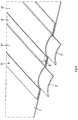
- a rollo assembly As its essential parts it comprises a flexible rollo screen 1, a rotatable winding shaft 2 to which a first end of the rollo screen 1 is attached for being wound on or off said winding shaft 2 and two opposite longitudinal guides 3 (only represented partially) extending in a longitudinal direction perpendicularly to the winding shaft for guiding opposite sides 4 of the rollo screen 1.
- the rollo screen 1 further is provided with longitudinally spaced elongate stiffeners 5 which extend substantially in a transverse direction in parallel to the winding shaft 2 between the opposite sides 4 of the rollo screen 1 and which are attached to the flexible rollo screen 1 (in a manner to be described later). These stiffeners 5 are biased for assuming a curved shape in said transverse direction (for example in correspondence with the shape of an inner side or headliner of a roof part of a vehicle).
- the rollo screen 1 may be provided by a pull beam 18 for manually operating the rollo assembly (as is generally known).
- the ends of the pull beam 18 as well as slide shoes 14 (elucidated below with respect to figures 8a and 8b ) at opposite ends of the stiffeners 5 may be guided in the guides 3
- each stiffener 5 comprises two stiffener parts 5' which comprise facing edges which are joined by a hinge member 6 extending in said transverse direction.
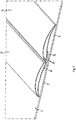
- Figure 2 shows a detail of an embodiment of the rollo assembly, in which the stiffener parts 5' in addition also are curved in said longitudinal direction. This allows them to be wound onto the winding shaft in a dense configuration, specifically when the stiffener parts 5' have a curvature in said longitudinal direction with such an orientation and with such a radius of curvature that the stiffener parts 5' closely conform to the effective outer curved shape of the winding shaft 2 (as defined by the winding shaft 2 and any amount of rollo screen 1 and stiffeners 5 wound thereon).
- FIG 2 too illustrates an embodiment of the hinge member 6 which comprises a central hinge body 7 connected to the rollo screen 1 (in any known matter, for example gluing, stitching, welding, moulding) and two spaced hinge axes 8 (shown in chain lines) each defining a hinged connection between the central hinge body 7 and a corresponding one of the stiffener parts 5'.
- the hinge axes 8 for example may comprise living hinges.
- Said hinge axes 8 may be defined as a part of the central hinge body 7, but in another embodiment the two stiffener parts 5' are integrally interconnected by an interconnecting part (for example said central hinge body 7) which is connected to the rollo screen 1 and wherein in said interconnecting part at least one living hinge is defined for realising a hinged connection.
- an interconnecting part for example said central hinge body 7
- said interconnecting part at least one living hinge is defined for realising a hinged connection.
- the hinge member 6 may extend substantially continuously in said transverse direction over the entire length of the stiffener parts 5' (as illustrated for example in figure 2 ).
- Figure 3 illustrates the possibility that the hinge member comprises a number of discrete transversally spaced hinge parts, in this case specifically two outer hinge parts 6' close to the opposite sides 4 of the rollo screen 1 and an intermediate hinge part 6" between said outer hinge parts 5'.
- Each of these hinge parts 6' ,6" may define one or more hinge axes.
- stiffener parts 5' have free edges 9 remote from their facing edges (the latter in this case substantially being defined by the parts of the stiffener parts 5' at the location of the hinge axes 8), which free edges 9 in the illustrated position in which said stiffener parts 5' are not wound onto the winding shaft 2, are spaced from the rollo screen 1.
- Figure 2 also shows that the flexible rollo screen 1 comprises a main layer 1' substantially defining the mechanical characteristics of the rollo screen 1 and having a surface (in this specific embodiment an upper surface) to which the stiffeners 5 are, indirectly through the hinge member, attached and an optical layer 1" attached to an opposite (lower) surface of said main layer 1'.
- Figure 4 illustrates an embodiment in which the stiffener parts 5' and the hinge member 6 have cooperating parts (generally indicated as 10) with matching shapes for defining the hinge axes 8.
- FIG 6 shows an embodiment in which the stiffener parts 5' of a stiffener 5 each are received in one of a pair of cloth pockets 11" provided on the rollo screen 1.
- the cloth pockets 11" are defined by a flexible cloth part 11 connected to the rollo screen 1.
- Said cloth part 11 comprises a central cloth part 11' that is located between the adjacent stiffener parts 5' (or, in other words, between the cloth pockets 11" defined by the cloth part 11) and that is attached to the rollo screen 1 (again in any convenient manner).
- the central cloth part 11' is sufficiently stiff to prevent a substantial collapse of said cloth part 11' in the longitudinal direction; as a result hinge axes 8 are defined where the central cloth part 11' meets the cloth pockets 11".
- the flexible rollo screen 1 at each stiffener is divided into two adjacent rollo screen parts 1' each having edge parts 12 which are folded back and connected to each other at respective folding lines 13 extending in the transverse direction.
- the edge parts 12 are attached to corresponding ones of the stiffener parts 5' and the hinge member is defined by said folding lines 13 (or at least a region of the rollo screen parts 1' in the vicinity of said folding lines 13).
- each stiffener part 5' at its opposite ends is provided with slide shoes 14 for cooperation with the respective longitudinal guides 3 (here illustrated in broken lines).
- the slide shoes 14 of two stiffener parts 5' of the same stiffener that cooperate with the same longitudinal guide 3 are interconnected by a hinge 15 which is located substantially in line (as illustrated schematically by a chain line in figure 8a ) with the hinge member 6 joining said stiffener parts 5'.
- said hinge member 6 defines two hinge axes 8 and the hinge 15 is located substantially halfway between these hinge axes 8; if the hinge member 6 would define only one hinge axis 8 (as, for example, in figure 5 ) the hinge 15 substantially would be aligned with said hinge axis 8.
- Figure 9 shows hollow stiffener parts 5'
- figure 10 shows stiffener parts 5' comprising each two parts 16,17 made of different materials. These are only examples for illustrating some of the possibilities for designing the stiffener parts 5'.
- the hinge member connecting adjacent stiffener parts may comprise a physical part, but also may be defined by a connection between said stiffener parts.
- the connection between the stiffener parts 5' and the rollo screen 1 may occur directly or indirectly.
Claims (16)
- Ensemble rouleau, comprenant un écran rouleau flexible (1), un arbre d'enroulement rotatif (2) sur lequel une première extrémité de l'écran rouleau (1) est attachée pour être enroulée ou déroulée dudit arbre d'enroulement (2) et deux guides longitudinaux opposés (3) s'étendant dans une direction longitudinale de façon perpendiculaire à l'arbre d'enroulement (2) pour guider des côtés opposés (4) de l'écran rouleau (1), dans lequel l'écran rouleau (1) est en outre pourvu de raidisseurs allongés espacés longitudinalement (5) s'étendant sensiblement dans une direction transversale en parallèle à l'arbre d'enroulement (2) entre les côtés opposés (4) de l'écran rouleau (1) et attachés à l'écran rouleau flexible (1), lesquels raidisseurs (5) sont sollicités pour adopter une forme incurvée dans ladite direction transversale, dans lequel chaque raidisseur (5) comprend deux parties de raidisseur (5') jointes au niveau de bords en regard de celles-ci, caractérisé en ce que chaque raidisseur (5) comprend en outre un organe d'articulation (6) s'étendant dans ladite direction transversale et joignant lesdits bords en regard et définissant au moins un axe d'articulation (8) pour, en partant d'une position opérationnelle dans laquelle le raidisseur (5) adopte ladite forme incurvée, permettre aux parties de raidisseur (5') de tourner l'une par rapport à l'autre tout en générant des forces pour redresser les parties de raidisseur.
- Ensemble rouleau selon la revendication 1, dans lequel les parties de raidisseur (5') sont également incurvées dans ladite direction longitudinale.
- Ensemble rouleau selon la revendication 2, dans lequel les parties de raidisseur (5') ont une courbure dans ladite direction longitudinale avec une orientation et un rayon de courbure tels que les parties de raidisseur (5') se conforment étroitement à la forme incurvée extérieure effective de l'arbre d'enroulement (2) lorsqu'elles sont enroulées dessus.
- Ensemble rouleau selon l'une quelconque des revendications précédentes, dans lequel l'organe d'articulation (6) s'étend sensiblement en continu dans ladite direction transversale sur toute la longueur des parties de raidisseur (5').
- Ensemble rouleau selon l'une quelconque des revendications 1 à 3, dans lequel l'organe d'articulation (6) comprend un certain nombre de parties d'articulation espacées transversalement discrètes (6', 6").
- Ensemble rouleau selon l'une quelconque des revendications précédentes, dans lequel l'organe d'articulation (6) comprend un corps d'articulation central (7) et deux axes d'articulation espacés (8) définissant chacun un raccordement articulé entre le corps d'articulation central (7) et une partie correspondante des parties de raidisseur (5').
- Ensemble rouleau selon l'une quelconque des revendications précédentes, dans lequel les deux parties de raidisseur (5') sont reliées d'un seul tenant par une partie de liaison (7) et dans lequel dans ladite partie de liaison (7) au moins une articulation souple (8) est définie pour réaliser un raccordement articulé.
- Ensemble rouleau selon l'une quelconque des revendications précédentes, dans lequel les parties de raidisseur (5') ont des bords libres (9) à distance de leurs bords en regard, lesquels bords libres (9) dans une position dans laquelle lesdites parties de raidisseur (5') ne sont pas enroulées sur l'arbre d'enroulement (2), sont espacés de l'écran rouleau (1).
- Ensemble rouleau selon l'une quelconque des revendications précédentes, dans lequel au moins l'une des deux parties de raidisseur (5') et de l'organe d'articulation (6) est attachée à l'écran rouleau (1).
- Ensemble rouleau selon l'une quelconque des revendications 1 à 5, dans lequel les parties de raidisseur (5') d'un raidisseur (5) sont reçues chacune dans une paire de poches (11") prévues sur l'écran rouleau (1), dans lequel les poches (11") sont définies par une partie en étoffe flexible (11) raccordée à l'écran rouleau (1) et dans lequel ladite partie en étoffe (11) comprend une partie en étoffe centrale (11') située entre les parties de raidisseur (5') adjacentes et attachée à l'écran rouleau (1), laquelle partie en étoffe centrale (11') est suffisamment raide pour empêcher un affaissement sensible de ladite partie en étoffe (11') dans la direction longitudinale, de sorte que des axes d'articulation (8) soient définis là où la partie en étoffe centrale (11') rencontre les poches (11").
- Ensemble rouleau selon l'une quelconque des revendications 1 à 5, dans lequel l'écran rouleau flexible (1) au niveau de chaque raidisseur (5) est divisé en deux parties d'écran rouleau adjacentes (1') ayant chacune des parties de bord (12) qui sont repliées et raccordées l'une à l'autre au niveau de lignes de pliure (13) respectives s'étendant dans la direction transversale et qui sont attachées à des parties correspondantes des parties de raidisseur (5') et dans lequel l'organe d'articulation est défini par lesdites lignes de pliure (13).
- Ensemble rouleau selon l'une quelconque des revendications précédentes, dans lequel chaque partie de raidisseur (5') au niveau de ses extrémités opposées est pourvue de patins coulissants (14) pour coopérer avec les guides longitudinaux (3) respectifs.
- Ensemble rouleau selon la revendication 12, dans lequel les patins coulissants (14) de deux parties de raidisseur (5') du même raidisseur (5) qui coopèrent avec le même guide longitudinal (3) sont reliés par une articulation (15) qui est située sensiblement alignée sur l'organe d'articulation (6) joignant lesdites parties de raidisseur (5').
- Ensemble rouleau selon l'une quelconque des revendications précédentes, dans lequel les parties de raidisseur (5') ont au moins l'une des configurations suivantes : un organe profilé, un organe creux, un organe réalisé en un seul matériau, un organe réalisé en au moins deux matériaux (16, 17), un organe en métal, un organe en plastique.
- Ensemble rouleau selon l'une quelconque des revendications précédentes, dans lequel les raidisseurs allongés (5) sont attachés à l'écran rouleau flexible (1) par l'une quelconque des méthodes suivantes : collage, piquage, soudage, moulage.
- Ensemble rouleau selon l'une quelconque des revendications précédentes, dans lequel l'écran rouleau flexible (1) comprend une couche principale (1') définissant sensiblement les caractéristiques mécaniques de l'écran rouleau (1) et ayant une surface sur laquelle sont attachés les raidisseurs (5), et une couche optique (1") attachée à une surface opposée de ladite couche principale (1').
Priority Applications (3)
| Application Number | Priority Date | Filing Date | Title |
|---|---|---|---|
| EP14195589.8A EP3028886B1 (fr) | 2014-12-01 | 2014-12-01 | Ensemble formant rouleau |
| CN201510808623.6A CN105644327B (zh) | 2014-12-01 | 2015-11-20 | 卷帘组件 |
| US14/952,561 US10017034B2 (en) | 2014-12-01 | 2015-11-25 | Rollo assembly |
Applications Claiming Priority (1)
| Application Number | Priority Date | Filing Date | Title |
|---|---|---|---|
| EP14195589.8A EP3028886B1 (fr) | 2014-12-01 | 2014-12-01 | Ensemble formant rouleau |
Publications (2)
| Publication Number | Publication Date |
|---|---|
| EP3028886A1 EP3028886A1 (fr) | 2016-06-08 |
| EP3028886B1 true EP3028886B1 (fr) | 2019-09-04 |
Family
ID=52013860
Family Applications (1)
| Application Number | Title | Priority Date | Filing Date |
|---|---|---|---|
| EP14195589.8A Active EP3028886B1 (fr) | 2014-12-01 | 2014-12-01 | Ensemble formant rouleau |
Country Status (3)
| Country | Link |
|---|---|
| US (1) | US10017034B2 (fr) |
| EP (1) | EP3028886B1 (fr) |
| CN (1) | CN105644327B (fr) |
Families Citing this family (4)
| Publication number | Priority date | Publication date | Assignee | Title |
|---|---|---|---|---|
| CN106795738A (zh) * | 2014-09-10 | 2017-05-31 | 亨特道格拉斯公司 | 用于建筑开口的卷帘覆盖物以及相关方法、系统和装置 |
| CA3000499A1 (fr) | 2017-04-13 | 2018-10-13 | Hunter Douglas Inc. | Revetement enrouleur a battant |
| CN110481290B (zh) * | 2019-09-04 | 2020-11-10 | 江苏铁锚明信交通科技有限公司 | 汽车天窗可调节降噪顶棚装置 |
| CN112282496B (zh) * | 2020-10-26 | 2022-05-17 | 国网新疆电力有限公司吐鲁番供电公司 | 变电站现场施工用围栏装置 |
Family Cites Families (19)
| Publication number | Priority date | Publication date | Assignee | Title |
|---|---|---|---|---|
| US675955A (en) * | 1901-03-29 | 1901-06-11 | William Raymond Kinnear | Fireproof blind. |
| US3653092A (en) * | 1970-07-27 | 1972-04-04 | Corning Glass Works | Hinge clip assembly |
| US4560245A (en) * | 1984-03-02 | 1985-12-24 | Sarver Patricia I | Vehicular windshield curtain for inhibiting heat transfer |
| DE8521854U1 (de) * | 1985-07-30 | 1985-09-12 | Seuster, Kurt, 5990 Altena | Rolltor |
| US4825921A (en) * | 1986-05-07 | 1989-05-02 | Rigter Steven M | Blinds, screens, partitions and doors |
| DE8909038U1 (fr) * | 1989-07-26 | 1989-11-23 | Henkenjohann, Johann, 4837 Verl, De | |
| FR2683582A1 (fr) * | 1991-11-07 | 1993-05-14 | Nergeco Sa | Panneau isolant deformable pour portes de manutention et portes correspondantes. |
| FR2770576B1 (fr) * | 1997-10-31 | 1999-12-24 | Nergeco Sa | Dispositif de securite et de protection pour une porte industrielle et/ou de manutention du type a relevage, munie d'au moins une sangle |
| US6207092B1 (en) * | 1999-05-28 | 2001-03-27 | K. Jabat, Inc. | Process for making a drag shield for a power mower |
| DE102005024657C5 (de) * | 2004-11-19 | 2016-04-21 | Webasto Ag | Rolloanordnung für ein Fahrzeug |
| FR2881463B1 (fr) * | 2005-01-31 | 2007-04-20 | Webasto Systemes Carrosserie S | Dispositif d'occultation a rideau enrouleur pour panneau permeable a la lumiere |
| FR2891495B1 (fr) | 2005-09-30 | 2007-11-30 | Wagon Sas | Dispositif d'occultation d'une surface vitree d'un vehicule automobile, a baleines a section en arc de cercle, et vehicule correspondant. |
| FR2925102B1 (fr) * | 2007-12-17 | 2011-07-01 | Peugeot Citroen Automobiles Sa | Dispositif d'occultation presentant un enrouleur galbe pour vitre ou panneau transparent, notamment pour vehicule automobile |
| US7945995B1 (en) * | 2008-03-27 | 2011-05-24 | Philips Electronics Ltd. | Metal living hinge |
| US10405936B2 (en) * | 2008-04-11 | 2019-09-10 | The Regents Of The University Of Michigan | Parallel kinematic mechanisms with decoupled rotational motions |
| US8261807B2 (en) * | 2008-04-28 | 2012-09-11 | Hunter Douglas Inc. | Dual fabric covering for architectural openings |
| JP2012240500A (ja) * | 2011-05-17 | 2012-12-10 | Aisin Seiki Co Ltd | 車両用ロールシェード装置 |
| NL2007194C2 (en) * | 2011-07-28 | 2013-01-29 | Unilux Nederland B V | Retractable and extendable covering device. |
| EP2783888B1 (fr) * | 2013-03-26 | 2016-11-02 | Inalfa Roof Systems Group B.V. | Ensemble store à enrouleur |
-
2014
- 2014-12-01 EP EP14195589.8A patent/EP3028886B1/fr active Active
-
2015
- 2015-11-20 CN CN201510808623.6A patent/CN105644327B/zh active Active
- 2015-11-25 US US14/952,561 patent/US10017034B2/en active Active
Non-Patent Citations (1)
| Title |
|---|
| None * |
Also Published As
| Publication number | Publication date |
|---|---|
| US10017034B2 (en) | 2018-07-10 |
| CN105644327B (zh) | 2020-01-17 |
| CN105644327A (zh) | 2016-06-08 |
| EP3028886A1 (fr) | 2016-06-08 |
| US20160152125A1 (en) | 2016-06-02 |
Similar Documents
| Publication | Publication Date | Title |
|---|---|---|
| EP3028886B1 (fr) | Ensemble formant rouleau | |
| US11370282B2 (en) | Guide and sunshade assembly provided therewith | |
| CN105936207A (zh) | 遮阳组件以及设有遮阳组件的天窗结构 | |
| US4160052A (en) | Corner for decorative and protective molding strip | |
| EP1917173B1 (fr) | Procede de fabrication d'un volant de direction et volant de direction fabrique a l'aide du procede | |
| ES2311937T3 (es) | Elemento de rigidizacion y procedimiento para la fabricacion de elemento de rigidizacion. | |
| DE60320022T2 (de) | Sonnenblende und dazugehörige befestigungsmethode für deren bezug | |
| DE2941176A1 (de) | Versteifungselement fuer profilleisten | |
| ES2541856T3 (es) | Perfil de material termoplástico para junta de estanqueidad o adorno para vehículos automóviles y procedimiento de fabricación de los perfiles | |
| US9956853B2 (en) | Glass pane having a profiled joint and trim, trim and production method for the glass pane | |
| EP2269856A1 (fr) | Pièce de formage pour renforcer la structure d'un déflecteur d'air d'un véhicule automobile | |
| WO2008017866A8 (fr) | Tuyau renforcé | |
| DE19634776C2 (de) | Dichtungsanordnung für eine Fensterscheibe eines Kraftfahrzeugs | |
| US11661792B2 (en) | Rolling shutter slat | |
| EP1698500B1 (fr) | Ensemble paresoleil | |
| US2273182A (en) | Sealing strip | |
| EP2979908A1 (fr) | Dispositif d'ombrage pour une partie plate transparente d'un vehicule automobile | |
| EP1927493B1 (fr) | Arceau pour un véhicule cabriolet | |
| CN203267735U (zh) | 遮挡卷帘设备 | |
| ES2526969T3 (es) | Techo interior con un canto superior periférico conformado | |
| WO2012076158A2 (fr) | Pièce composite à liaison par soudure | |
| CN110040078B (zh) | 用于实施具有复合式覆盖层的包覆元件的实施方法 | |
| EP2039966B1 (fr) | Dispositif de soufflet | |
| JP3890031B2 (ja) | 手摺等の継手部材 | |
| JP2010195333A (ja) | ガラスラン |
Legal Events
| Date | Code | Title | Description |
|---|---|---|---|
| PUAI | Public reference made under article 153(3) epc to a published international application that has entered the european phase |
Free format text: ORIGINAL CODE: 0009012 |
|
| AK | Designated contracting states |
Kind code of ref document: A1 Designated state(s): AL AT BE BG CH CY CZ DE DK EE ES FI FR GB GR HR HU IE IS IT LI LT LU LV MC MK MT NL NO PL PT RO RS SE SI SK SM TR |
|
| AX | Request for extension of the european patent |
Extension state: BA ME |
|
| STAA | Information on the status of an ep patent application or granted ep patent |
Free format text: STATUS: REQUEST FOR EXAMINATION WAS MADE |
|
| 17P | Request for examination filed |
Effective date: 20161206 |
|
| RBV | Designated contracting states (corrected) |
Designated state(s): AL AT BE BG CH CY CZ DE DK EE ES FI FR GB GR HR HU IE IS IT LI LT LU LV MC MK MT NL NO PL PT RO RS SE SI SK SM TR |
|
| RIC1 | Information provided on ipc code assigned before grant |
Ipc: B60J 7/00 20060101AFI20190411BHEP Ipc: B60J 1/20 20060101ALI20190411BHEP |
|
| GRAP | Despatch of communication of intention to grant a patent |
Free format text: ORIGINAL CODE: EPIDOSNIGR1 |
|
| STAA | Information on the status of an ep patent application or granted ep patent |
Free format text: STATUS: GRANT OF PATENT IS INTENDED |
|
| INTG | Intention to grant announced |
Effective date: 20190517 |
|
| GRAS | Grant fee paid |
Free format text: ORIGINAL CODE: EPIDOSNIGR3 |
|
| GRAA | (expected) grant |
Free format text: ORIGINAL CODE: 0009210 |
|
| STAA | Information on the status of an ep patent application or granted ep patent |
Free format text: STATUS: THE PATENT HAS BEEN GRANTED |
|
| AK | Designated contracting states |
Kind code of ref document: B1 Designated state(s): AL AT BE BG CH CY CZ DE DK EE ES FI FR GB GR HR HU IE IS IT LI LT LU LV MC MK MT NL NO PL PT RO RS SE SI SK SM TR |
|
| REG | Reference to a national code |
Ref country code: GB Ref legal event code: FG4D |
|
| REG | Reference to a national code |
Ref country code: CH Ref legal event code: EP |
|
| REG | Reference to a national code |
Ref country code: AT Ref legal event code: REF Ref document number: 1174868 Country of ref document: AT Kind code of ref document: T Effective date: 20190915 |
|
| REG | Reference to a national code |
Ref country code: DE Ref legal event code: R096 Ref document number: 602014052884 Country of ref document: DE |
|
| REG | Reference to a national code |
Ref country code: IE Ref legal event code: FG4D |
|
| REG | Reference to a national code |
Ref country code: NL Ref legal event code: MP Effective date: 20190904 |
|
| REG | Reference to a national code |
Ref country code: LT Ref legal event code: MG4D |
|
| PG25 | Lapsed in a contracting state [announced via postgrant information from national office to epo] |
Ref country code: BG Free format text: LAPSE BECAUSE OF FAILURE TO SUBMIT A TRANSLATION OF THE DESCRIPTION OR TO PAY THE FEE WITHIN THE PRESCRIBED TIME-LIMIT Effective date: 20191204 Ref country code: SE Free format text: LAPSE BECAUSE OF FAILURE TO SUBMIT A TRANSLATION OF THE DESCRIPTION OR TO PAY THE FEE WITHIN THE PRESCRIBED TIME-LIMIT Effective date: 20190904 Ref country code: HR Free format text: LAPSE BECAUSE OF FAILURE TO SUBMIT A TRANSLATION OF THE DESCRIPTION OR TO PAY THE FEE WITHIN THE PRESCRIBED TIME-LIMIT Effective date: 20190904 Ref country code: LT Free format text: LAPSE BECAUSE OF FAILURE TO SUBMIT A TRANSLATION OF THE DESCRIPTION OR TO PAY THE FEE WITHIN THE PRESCRIBED TIME-LIMIT Effective date: 20190904 Ref country code: FI Free format text: LAPSE BECAUSE OF FAILURE TO SUBMIT A TRANSLATION OF THE DESCRIPTION OR TO PAY THE FEE WITHIN THE PRESCRIBED TIME-LIMIT Effective date: 20190904 Ref country code: NO Free format text: LAPSE BECAUSE OF FAILURE TO SUBMIT A TRANSLATION OF THE DESCRIPTION OR TO PAY THE FEE WITHIN THE PRESCRIBED TIME-LIMIT Effective date: 20191204 |
|
| PG25 | Lapsed in a contracting state [announced via postgrant information from national office to epo] |
Ref country code: AL Free format text: LAPSE BECAUSE OF FAILURE TO SUBMIT A TRANSLATION OF THE DESCRIPTION OR TO PAY THE FEE WITHIN THE PRESCRIBED TIME-LIMIT Effective date: 20190904 Ref country code: ES Free format text: LAPSE BECAUSE OF FAILURE TO SUBMIT A TRANSLATION OF THE DESCRIPTION OR TO PAY THE FEE WITHIN THE PRESCRIBED TIME-LIMIT Effective date: 20190904 Ref country code: LV Free format text: LAPSE BECAUSE OF FAILURE TO SUBMIT A TRANSLATION OF THE DESCRIPTION OR TO PAY THE FEE WITHIN THE PRESCRIBED TIME-LIMIT Effective date: 20190904 Ref country code: RS Free format text: LAPSE BECAUSE OF FAILURE TO SUBMIT A TRANSLATION OF THE DESCRIPTION OR TO PAY THE FEE WITHIN THE PRESCRIBED TIME-LIMIT Effective date: 20190904 Ref country code: GR Free format text: LAPSE BECAUSE OF FAILURE TO SUBMIT A TRANSLATION OF THE DESCRIPTION OR TO PAY THE FEE WITHIN THE PRESCRIBED TIME-LIMIT Effective date: 20191205 |
|
| REG | Reference to a national code |
Ref country code: AT Ref legal event code: MK05 Ref document number: 1174868 Country of ref document: AT Kind code of ref document: T Effective date: 20190904 |
|
| PG25 | Lapsed in a contracting state [announced via postgrant information from national office to epo] |
Ref country code: PT Free format text: LAPSE BECAUSE OF FAILURE TO SUBMIT A TRANSLATION OF THE DESCRIPTION OR TO PAY THE FEE WITHIN THE PRESCRIBED TIME-LIMIT Effective date: 20200106 Ref country code: IT Free format text: LAPSE BECAUSE OF FAILURE TO SUBMIT A TRANSLATION OF THE DESCRIPTION OR TO PAY THE FEE WITHIN THE PRESCRIBED TIME-LIMIT Effective date: 20190904 Ref country code: RO Free format text: LAPSE BECAUSE OF FAILURE TO SUBMIT A TRANSLATION OF THE DESCRIPTION OR TO PAY THE FEE WITHIN THE PRESCRIBED TIME-LIMIT Effective date: 20190904 Ref country code: NL Free format text: LAPSE BECAUSE OF FAILURE TO SUBMIT A TRANSLATION OF THE DESCRIPTION OR TO PAY THE FEE WITHIN THE PRESCRIBED TIME-LIMIT Effective date: 20190904 Ref country code: AT Free format text: LAPSE BECAUSE OF FAILURE TO SUBMIT A TRANSLATION OF THE DESCRIPTION OR TO PAY THE FEE WITHIN THE PRESCRIBED TIME-LIMIT Effective date: 20190904 Ref country code: PL Free format text: LAPSE BECAUSE OF FAILURE TO SUBMIT A TRANSLATION OF THE DESCRIPTION OR TO PAY THE FEE WITHIN THE PRESCRIBED TIME-LIMIT Effective date: 20190904 Ref country code: EE Free format text: LAPSE BECAUSE OF FAILURE TO SUBMIT A TRANSLATION OF THE DESCRIPTION OR TO PAY THE FEE WITHIN THE PRESCRIBED TIME-LIMIT Effective date: 20190904 |
|
| PG25 | Lapsed in a contracting state [announced via postgrant information from national office to epo] |
Ref country code: IS Free format text: LAPSE BECAUSE OF FAILURE TO SUBMIT A TRANSLATION OF THE DESCRIPTION OR TO PAY THE FEE WITHIN THE PRESCRIBED TIME-LIMIT Effective date: 20200224 Ref country code: SK Free format text: LAPSE BECAUSE OF FAILURE TO SUBMIT A TRANSLATION OF THE DESCRIPTION OR TO PAY THE FEE WITHIN THE PRESCRIBED TIME-LIMIT Effective date: 20190904 Ref country code: SM Free format text: LAPSE BECAUSE OF FAILURE TO SUBMIT A TRANSLATION OF THE DESCRIPTION OR TO PAY THE FEE WITHIN THE PRESCRIBED TIME-LIMIT Effective date: 20190904 Ref country code: CZ Free format text: LAPSE BECAUSE OF FAILURE TO SUBMIT A TRANSLATION OF THE DESCRIPTION OR TO PAY THE FEE WITHIN THE PRESCRIBED TIME-LIMIT Effective date: 20190904 |
|
| REG | Reference to a national code |
Ref country code: DE Ref legal event code: R097 Ref document number: 602014052884 Country of ref document: DE |
|
| PLBE | No opposition filed within time limit |
Free format text: ORIGINAL CODE: 0009261 |
|
| STAA | Information on the status of an ep patent application or granted ep patent |
Free format text: STATUS: NO OPPOSITION FILED WITHIN TIME LIMIT |
|
| PG2D | Information on lapse in contracting state deleted |
Ref country code: IS |
|
| PG25 | Lapsed in a contracting state [announced via postgrant information from national office to epo] |
Ref country code: DK Free format text: LAPSE BECAUSE OF FAILURE TO SUBMIT A TRANSLATION OF THE DESCRIPTION OR TO PAY THE FEE WITHIN THE PRESCRIBED TIME-LIMIT Effective date: 20190904 Ref country code: IS Free format text: LAPSE BECAUSE OF FAILURE TO SUBMIT A TRANSLATION OF THE DESCRIPTION OR TO PAY THE FEE WITHIN THE PRESCRIBED TIME-LIMIT Effective date: 20200105 |
|
| REG | Reference to a national code |
Ref country code: CH Ref legal event code: PL |
|
| 26N | No opposition filed |
Effective date: 20200605 |
|
| REG | Reference to a national code |
Ref country code: BE Ref legal event code: MM Effective date: 20191231 |
|
| PG25 | Lapsed in a contracting state [announced via postgrant information from national office to epo] |
Ref country code: MC Free format text: LAPSE BECAUSE OF FAILURE TO SUBMIT A TRANSLATION OF THE DESCRIPTION OR TO PAY THE FEE WITHIN THE PRESCRIBED TIME-LIMIT Effective date: 20190904 Ref country code: SI Free format text: LAPSE BECAUSE OF FAILURE TO SUBMIT A TRANSLATION OF THE DESCRIPTION OR TO PAY THE FEE WITHIN THE PRESCRIBED TIME-LIMIT Effective date: 20190904 |
|
| GBPC | Gb: european patent ceased through non-payment of renewal fee |
Effective date: 20191204 |
|
| PG25 | Lapsed in a contracting state [announced via postgrant information from national office to epo] |
Ref country code: LU Free format text: LAPSE BECAUSE OF NON-PAYMENT OF DUE FEES Effective date: 20191201 Ref country code: IE Free format text: LAPSE BECAUSE OF NON-PAYMENT OF DUE FEES Effective date: 20191201 Ref country code: GB Free format text: LAPSE BECAUSE OF NON-PAYMENT OF DUE FEES Effective date: 20191204 |
|
| PG25 | Lapsed in a contracting state [announced via postgrant information from national office to epo] |
Ref country code: LI Free format text: LAPSE BECAUSE OF NON-PAYMENT OF DUE FEES Effective date: 20191231 Ref country code: CH Free format text: LAPSE BECAUSE OF NON-PAYMENT OF DUE FEES Effective date: 20191231 Ref country code: BE Free format text: LAPSE BECAUSE OF NON-PAYMENT OF DUE FEES Effective date: 20191231 |
|
| PG25 | Lapsed in a contracting state [announced via postgrant information from national office to epo] |
Ref country code: CY Free format text: LAPSE BECAUSE OF FAILURE TO SUBMIT A TRANSLATION OF THE DESCRIPTION OR TO PAY THE FEE WITHIN THE PRESCRIBED TIME-LIMIT Effective date: 20190904 |
|
| PG25 | Lapsed in a contracting state [announced via postgrant information from national office to epo] |
Ref country code: HU Free format text: LAPSE BECAUSE OF FAILURE TO SUBMIT A TRANSLATION OF THE DESCRIPTION OR TO PAY THE FEE WITHIN THE PRESCRIBED TIME-LIMIT; INVALID AB INITIO Effective date: 20141201 Ref country code: MT Free format text: LAPSE BECAUSE OF FAILURE TO SUBMIT A TRANSLATION OF THE DESCRIPTION OR TO PAY THE FEE WITHIN THE PRESCRIBED TIME-LIMIT Effective date: 20190904 |
|
| PG25 | Lapsed in a contracting state [announced via postgrant information from national office to epo] |
Ref country code: TR Free format text: LAPSE BECAUSE OF FAILURE TO SUBMIT A TRANSLATION OF THE DESCRIPTION OR TO PAY THE FEE WITHIN THE PRESCRIBED TIME-LIMIT Effective date: 20190904 |
|
| PG25 | Lapsed in a contracting state [announced via postgrant information from national office to epo] |
Ref country code: MK Free format text: LAPSE BECAUSE OF FAILURE TO SUBMIT A TRANSLATION OF THE DESCRIPTION OR TO PAY THE FEE WITHIN THE PRESCRIBED TIME-LIMIT Effective date: 20190904 |
|
| PGFP | Annual fee paid to national office [announced via postgrant information from national office to epo] |
Ref country code: DE Payment date: 20221228 Year of fee payment: 9 |
|
| PGFP | Annual fee paid to national office [announced via postgrant information from national office to epo] |
Ref country code: FR Payment date: 20231227 Year of fee payment: 10 |