EP3021982B1 - Air caps with face geometry inserts for liquid spray guns - Google Patents
Air caps with face geometry inserts for liquid spray guns Download PDFInfo
- Publication number
- EP3021982B1 EP3021982B1 EP14742701.7A EP14742701A EP3021982B1 EP 3021982 B1 EP3021982 B1 EP 3021982B1 EP 14742701 A EP14742701 A EP 14742701A EP 3021982 B1 EP3021982 B1 EP 3021982B1
- Authority
- EP
- European Patent Office
- Prior art keywords
- air
- face geometry
- base member
- geometry insert
- air cap
- Prior art date
- Legal status (The legal status is an assumption and is not a legal conclusion. Google has not performed a legal analysis and makes no representation as to the accuracy of the status listed.)
- Active
Links
Images


Classifications
-
- B—PERFORMING OPERATIONS; TRANSPORTING
- B05—SPRAYING OR ATOMISING IN GENERAL; APPLYING FLUENT MATERIALS TO SURFACES, IN GENERAL
- B05B—SPRAYING APPARATUS; ATOMISING APPARATUS; NOZZLES
- B05B7/00—Spraying apparatus for discharge of liquids or other fluent materials from two or more sources, e.g. of liquid and air, of powder and gas
- B05B7/02—Spray pistols; Apparatus for discharge
- B05B7/08—Spray pistols; Apparatus for discharge with separate outlet orifices, e.g. to form parallel jets, i.e. the axis of the jets being parallel, to form intersecting jets, i.e. the axis of the jets converging but not necessarily intersecting at a point
- B05B7/0807—Spray pistols; Apparatus for discharge with separate outlet orifices, e.g. to form parallel jets, i.e. the axis of the jets being parallel, to form intersecting jets, i.e. the axis of the jets converging but not necessarily intersecting at a point to form intersecting jets
- B05B7/0815—Spray pistols; Apparatus for discharge with separate outlet orifices, e.g. to form parallel jets, i.e. the axis of the jets being parallel, to form intersecting jets, i.e. the axis of the jets converging but not necessarily intersecting at a point to form intersecting jets with at least one gas jet intersecting a jet constituted by a liquid or a mixture containing a liquid for controlling the shape of the latter
-
- B—PERFORMING OPERATIONS; TRANSPORTING
- B05—SPRAYING OR ATOMISING IN GENERAL; APPLYING FLUENT MATERIALS TO SURFACES, IN GENERAL
- B05B—SPRAYING APPARATUS; ATOMISING APPARATUS; NOZZLES
- B05B7/00—Spraying apparatus for discharge of liquids or other fluent materials from two or more sources, e.g. of liquid and air, of powder and gas
- B05B7/02—Spray pistols; Apparatus for discharge
- B05B7/06—Spray pistols; Apparatus for discharge with at least one outlet orifice surrounding another approximately in the same plane
- B05B7/062—Spray pistols; Apparatus for discharge with at least one outlet orifice surrounding another approximately in the same plane with only one liquid outlet and at least one gas outlet
- B05B7/066—Spray pistols; Apparatus for discharge with at least one outlet orifice surrounding another approximately in the same plane with only one liquid outlet and at least one gas outlet with an inner liquid outlet surrounded by at least one annular gas outlet
-
- B—PERFORMING OPERATIONS; TRANSPORTING
- B05—SPRAYING OR ATOMISING IN GENERAL; APPLYING FLUENT MATERIALS TO SURFACES, IN GENERAL
- B05B—SPRAYING APPARATUS; ATOMISING APPARATUS; NOZZLES
- B05B7/00—Spraying apparatus for discharge of liquids or other fluent materials from two or more sources, e.g. of liquid and air, of powder and gas
- B05B7/02—Spray pistols; Apparatus for discharge
- B05B7/08—Spray pistols; Apparatus for discharge with separate outlet orifices, e.g. to form parallel jets, i.e. the axis of the jets being parallel, to form intersecting jets, i.e. the axis of the jets converging but not necessarily intersecting at a point
- B05B7/0807—Spray pistols; Apparatus for discharge with separate outlet orifices, e.g. to form parallel jets, i.e. the axis of the jets being parallel, to form intersecting jets, i.e. the axis of the jets converging but not necessarily intersecting at a point to form intersecting jets
- B05B7/0861—Spray pistols; Apparatus for discharge with separate outlet orifices, e.g. to form parallel jets, i.e. the axis of the jets being parallel, to form intersecting jets, i.e. the axis of the jets converging but not necessarily intersecting at a point to form intersecting jets with one single jet constituted by a liquid or a mixture containing a liquid and several gas jets
-
- B—PERFORMING OPERATIONS; TRANSPORTING
- B05—SPRAYING OR ATOMISING IN GENERAL; APPLYING FLUENT MATERIALS TO SURFACES, IN GENERAL
- B05B—SPRAYING APPARATUS; ATOMISING APPARATUS; NOZZLES
- B05B7/00—Spraying apparatus for discharge of liquids or other fluent materials from two or more sources, e.g. of liquid and air, of powder and gas
- B05B7/02—Spray pistols; Apparatus for discharge
- B05B7/08—Spray pistols; Apparatus for discharge with separate outlet orifices, e.g. to form parallel jets, i.e. the axis of the jets being parallel, to form intersecting jets, i.e. the axis of the jets converging but not necessarily intersecting at a point
- B05B7/0807—Spray pistols; Apparatus for discharge with separate outlet orifices, e.g. to form parallel jets, i.e. the axis of the jets being parallel, to form intersecting jets, i.e. the axis of the jets converging but not necessarily intersecting at a point to form intersecting jets
- B05B7/0815—Spray pistols; Apparatus for discharge with separate outlet orifices, e.g. to form parallel jets, i.e. the axis of the jets being parallel, to form intersecting jets, i.e. the axis of the jets converging but not necessarily intersecting at a point to form intersecting jets with at least one gas jet intersecting a jet constituted by a liquid or a mixture containing a liquid for controlling the shape of the latter
- B05B7/0838—Spray pistols; Apparatus for discharge with separate outlet orifices, e.g. to form parallel jets, i.e. the axis of the jets being parallel, to form intersecting jets, i.e. the axis of the jets converging but not necessarily intersecting at a point to form intersecting jets with at least one gas jet intersecting a jet constituted by a liquid or a mixture containing a liquid for controlling the shape of the latter comprising a single means controlling simultaneously the flow rates of shaping and spraying gas jets
Definitions
- This disclosure relates to air caps for liquid spray head assemblies and/or for liquid spray guns.
- molded air caps with face geometry inserts are molded air caps with face geometry inserts. Face geometry inserts provided herein may be effective to provide symmetrical and balanced spray patterns.
- Spray guns are known for use in the application of liquids such as paints (and other coatings) across many industries.
- Such spray guns commonly include a gun body, a trigger, a spray head assembly, a reservoir for holding a liquid to be sprayed, and an air source to assist in atomizing and propelling the liquid onto a surface to be coated.
- the liquid may accumulate on the exterior and interior surfaces of the spray guns.
- spray guns were fabricated from metal and for a long-use life, which included reuse after cleaning and/or maintenance.
- face geometry inserts In order to address ensuring individual parts fabricated for spray guns are aligned to deliver desired spray patterns, face geometry inserts have been developed. Specifically provided herein are molded air caps with face geometry inserts for use with liquid spray head assemblies and/or for liquid spray guns.
- Each aperture of the pair of shaping air apertures may be symmetric with respect to the spray axis.
- the face geometry insert may further comprise a center frame opening such that the center frame opening is concentric with the nozzle tip opening.
- the face geometry insert may further comprise at least one pair of capping features.
- the base member may further comprise at least one pair of capping features.
- the face geometry insert may further comprise at least one pair of auxiliary air holes.
- the face geometry insert may comprise at least one hinge. Or, the face geometry insert may comprise a non-planar body and no hinges.
- the face geometry insert is removable from the base member body.
- the face geometry insert may snap-fit into the base member body.
- the face geometry insert may bend-fit into the base member body.
- the face geometry insert is welded to the base member body.
- All embodiments may further comprise a nozzle tip affixed to the face geometry insert.
- the nozzle tip may be removably affixed to the center frame of the face geometry insert.
- the nozzle tip may be integral to the face geometry insert.
- An included angle ⁇ with respect to the relation among the spray axis and a plane of each surface of the pair of shaping air apertures is in the range of 25° to 85°.
- kits comprising a plurality of air caps as disclosed herein with one or more features of various sizes.
- the pairs of shaping air apertures of at least two of the face geometry inserts may have different configurations and/or the center frame openings of at least two of the face geometry inserts may have different dimensions and/or nozzle tips of different dimensions may be included.
- the face geometry insert may be fabricated by molding or stamping.
- the face geometry insert may be moved from an initial position to an assembled position upon assembly with the base member.
- the face geometry insert and the base member independently comprise a metal, a polymer, a ceramic, a filled material, or combinations thereof.
- Another aspect is a spray head assembly for attachment to a liquid spray gun, the spray head assembly comprising a barrel and any of the air caps disclosed herein along with a nozzle tip.
- Liquid spray guns are also provided, which comprise: spray head assembly as disclosed herein assembled with a liquid spray gun body.
- air caps for liquid spray head assemblies and/or for liquid spray guns are provided.
- molded air caps with face geometry inserts are effective to provide a refined spray pattern, which is a spray pattern suitable for a desired application that is balanced, symmetrical, and has smooth transitions in coating spray density within the pattern. For smooth transitions, there are no excessively sharp changes in coating amount/density.
- current methods used to manufacture these components may involve casting or machining where creating pathways for air and/or liquid flow, and in particular for atomization, usually requires using labor and/or capitol intensive secondary operations, such as precision drilling. The secondary operations are susceptible to variations in the size and positioning of critical air outlets.
- the face geometry inserts are components wherein the location, size, and spacing of critical air and/or liquid openings are already aligned/designed into a single piece
- a face geometry insert is retained to a base member to form an air cap.
- the base member may be the larger of the two pieces, and it is fabricated easily as one piece without a need for precisely aligned features, such as primary/shaping air apertures/holes.
- the face geometry insert may be the smaller of the two pieces and its manufacture and the features therein may be precisely controlled with minimal variation in dimensions that are critical to correct operation.
- the base member may be fabricated as needed, as one part or a combination of parts.
- Face geometry inserts may be color-coded with base members and/or barrels for quick recognition of material/job specified combinations.
- the face geometry inserts described herein can be designed to achieve a variety of patterns as desired. Indeed, customized face geometry inserts may be combined (assembled) with a universal base member body in order to create a wide range of air cap configurations.
- spray patterns are produced by liquid exiting a liquid nozzle port (also referred to as a fluid tip) of a barrel/nozzle, the port being centrally located within the center hole of an air cap and as such is surrounded by a center annular air outlet that channels compressed air and a pair of opposed inwardly directed shaping air apertures that also channel compressed air arranged on opposite sides and spaced forwardly of the center annular air outlet.
- a liquid nozzle port also referred to as a fluid tip
- the port being centrally located within the center hole of an air cap and as such is surrounded by a center annular air outlet that channels compressed air and a pair of opposed inwardly directed shaping air apertures that also channel compressed air arranged on opposite sides and spaced forwardly of the center annular air outlet.
- Air streams or jets from the shaping air apertures may be adjustable to adapt the spray nozzle for dispensing different liquids and/or change the geometry of the spray pattern. Air streams from the auxiliary air holes in the air cap may further atomize the liquid and/or interact with the shaping air streams to further refine the spray pattern.
- Face geometry inserts and base members may be fabricated by molding or stamping or other methods related to manipulating/processing plastics and/or metals known in the art. They may be fabricated in the same way or differently, by the same materials or different ones.
- the fabrication methods include introducing first and second materials in their molten state to first and second molds, respectively, to create formed molten materials, and then cooling the formed molten materials.
- Suitable materials independently include, but are not limited to, metals, polymers, ceramics, and other materials such as glass, filled-materials, and ceramics.
- Suitable metals include, but are not limited to, aluminum, copper, or steel, including combinations and/or alloys thereof.
- Suitable polymers independently include, but are not limited to, polyurethanes, polyolefins (e.g., polypropylenes), polyamides (e.g., nylons including amorphous nylons), polyesters, fluoropolymers, and polycarbonates), and others.
- the polymers may be opaque, translucent, or transparent as suitable for the application.
- Exemplary filled-material is glass-filled polypropylene.
- the molds can be designed with features, such as steel core pins that form resulting openings in the molded parts, the openings including but not being limited to shaping air apertures, auxiliary air holes, and center frame openings, and overall geometries as desired.
- the face geometry insert is formed in one-step, including formation of its openings.
- openings may be drilled, for example by laser drilling, in a separate step, Face geometry inserts may contain other features as desired to direct air.
- Face geometry inserts may also be fabricated by stamping, for example by metal stamping.
- photolithographic methods that involve additive processes like metal plating and/or subtractive processes like chemical etching may be suitable for forming face geometry inserts and/or their features.
- the face geometry insert may be changeable, flexible, and/or deformable as needed to permit it to go from an initial position to an assembled position upon assembly with or fitting into the base member.
- Flex it is contemplated that the face geometry insert is sufficiently flexible to bend over a least some portion of its length and is sufficient to achieve an included angle between shaping air streams of up to 85 degrees. That is, materials of construction have adequate elasticity and/or plasticity to allow change from an initial position to an assembled position.
- the presence of hinges may facilitate assembly of the face geometry insert with the base member or the ability to deliberately distort the face geometry insert from its initial position, which is an unassembled configuration, into an assembled configuration by bending the face geometry insert at one or two or more predefined locations.
- the face geometry insert may be snap-fit, bend-fit, welded, bonded, or otherwise retained to a base member such that a substantially tight seal is achieved.
- the seal may be air tight, or it may tolerate some venting. In this way, air exits the air caps through designed openings, including but not limited to a nozzle tip opening, shaping air apertures, and optional auxiliary air holes.
- the face geometry insert may, for example, be snap-fit onto or into the top side or underside of the base member. With snap-fit assembly, the face geometry insert may be removable; with welding, the face geometry insert usually is not removable. For welding, one method is ultrasonics, where an energy director may be present to ensure that the parts are correctly adhered to one another.
- the base member has one or more receiving features such as a slight recess, groove, and/or other locating feature that cooperates with the face geometry insert.
- the face geometry insert With respect to aligning and registering parts, the face geometry insert, with its openings pre-designed and already precisely aligned onto a single piece, receipt into the base member ensures that the registration continues to be maintained upon assembly.
- the face geometry insert is removable from the base member. In one or more other embodiments, the face geometry insert is non-removable.
- the face geometry insert may be shaped as needed. other embodiments, the body of the face geometry insert may be disc-shaped, circular, oval, or even square.
- the face geometry insert comprises openings located in a bridging portion, which means the bridging portion is the material between the various openings including but not limited to shaping air apertures.
- the face geometry insert may contain as many openings or pairs of openings as needed. Some embodiments provide 2, 3, 4, 5, or more openings. It is understood that a base member of the air cap will be configured to deliver air as needed to the openings of the face geometry insert.
- the exit air openings may be formed, for example, through a surface of the body of the base member. As an exit air structure at least one pair of air horns is provided. The at least one pair of air horns may be attached to or received by or integral with the base member body.
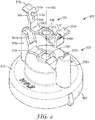
- an air cap 100 comprises a base member 102 and a face geometry insert 104.
- the face geometry insert 104 comprises a bridging portion 105, one or more pairs of shaping air apertures 110a, 110b and 110c, 110d and is retained to the base member 102.
- the face geometry insert 104 may also comprise a center frame 113 and a center frame opening 112. Air flow surface 115 defines how air flows through the center frame opening 112. Upon assembly with into a spray head assembly, a liquid nozzle port will reside within and preferably concentrically with the center frame opening 112. As will be discussed with respect to FIGS.
- air will flow through the annulus formed between the air flow surface 115 (315, 415) and the outside diameter of the liquid nozzle port (352, 452).
- the air flow surface 115 may be designed in any angle, depth, shape, or otherwise to achieve a spray pattern suitable for a particular application. Upon assembly with a liquid spray gun, positioning of the pair of shaping air apertures and the center frame opening is effective to provide a refined spray pattern from the liquid spray gun.
- Optional auxiliary air holes 117 may be formed in the face geometry insert 104.
- the base member 102 is configured as needed to supply/channel air to the auxiliary air holes 117 in the face member insert 104.
- the base member 102 comprises at least one pair of air horns 108 each comprising an exit air opening 107, a base member body 116, and a nozzle tip opening 106.
- the exit air openings in this embodiment are formed through an exit air structure, such as at least one pair of air horns 108a, 108b as exemplified in FIG. 1 .
- the base member further comprises a receiving feature 114 for receiving the face geometry insert 104.
- the base member 102 may optionally further comprise one or more capping features 120a, 120b to facilitate affixing and/or registering the face geometry insert 104 to base member 102. While the embodiment of FIG.
- the center frame opening 112 of the face geometry insert 104 may be axially and/or concentrically aligned with the nozzle tip opening 106. Both openings may be independently shaped as desired. In some embodiments the openings are independently circular or oval, or indeed other alternative shapes and / or geometries.
- a spray axis 150 extends through the center of the nozzle tip opening 106 and the center frame opening 112. When a liquid nozzle port is present, the spray axis extends through the liquid nozzle port center also.
- each aperture of the pair of shaping air apertures is located on an opposite side of the spray axis 150. That is, shaping air aperture 110a is on an opposite side of spray axis 150 as compared to shaping air aperture 110b.
- shaping air aperture 110c is on an opposite side of spray axis 150 as compared to shaping air aperture 110d.
- the shaping air apertures 110a, 110b and/or 110c, 110d are symmetric with respect to the spray axis 150.
- pairs of apertures 110a, 110b and 110c, 110d are symmetric with respect to the spray axis 150.
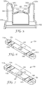
- FIG. 2 which is an exploded perspective view of an air cap according to another embodiment; FIG. 3 , which is a side view; FIG. 4 , which is a perspective view; and FIG. 5 , which is a cross-section view; the air cap 500 comprises a base member 502 and a face geometry insert 504.
- the capping features 520a, 520b are part of the face geometry insert 504.
- the face geometry insert 504 also comprises a bridging portion 505 and one or more pairs of shaping air apertures 510a, 510b and 510c, 510d and is retained to the base member 502.
- the face geometry insert 504 may also comprise a center frame 513 and a center frame opening 512.
- Air flow surface 515 defines how air flows through the center frame opening 512.
- a liquid nozzle port Upon assembly with into a spray gun assembly, a liquid nozzle port will reside in the center frame opening 512. Air will flow through the annulus formed between the air flow surface 515 and the outside diameter of the liquid nozzle port.
- the air flow surface 515 may be designed in any angle, depth, shape, or otherwise overall geometry to achieve a spray pattern suitable for a particular application.
- positioning of the pair of shaping air apertures and the center frame opening is effective to provide a symmetrical spray pattern from the liquid spray gun.
- the base member 502 comprises at least one pair of exit air openings 507a, 507b, a base member body 516, and a nozzle tip opening 506.
- the base member further comprises a receiving feature 514 for receiving the face geometry insert 504.
- the center frame opening 512 of the face geometry insert 504 may be axially and/or concentrically with the nozzle tip opening 506. Both openings may be independently shaped as desired. In some embodiments the openings are independently circular or oval or non-circular.
- a spray axis 550 extends through the center of the nozzle tip opening 506 and the center frame opening 512. When a liquid nozzle tip is present, the spray axis extends through the center of the liquid nozzle port also.
- each aperture of the pair of shaping air apertures is located on an opposite side of the spray axis 550. That is, shaping air aperture 510a is on an opposite side of spray axis 550 as compared to shaping air aperture 510b.
- shaping air aperture 510c is on an opposite side of spray axis 150 as compared to shaping air aperture 510d.
- the air apertures 510a, 510b and/or 510c, 510d are symmetric with respect to the spray axis 550.
- the pair of apertures 510a, 510b (not shown in Figure 2 ) and/or 510c, 510d are symmetric with respect to the spray axis 550.
- the air cap of FIG. 5 with markings to show an exemplary alignment of features. That is, the markings provide a way to determine included angles with respect to the spray axis 50 and one or both pairs of shaping air apertures 510a & 510b and/or 510c & 510b.
- An included angle ⁇ which is defined by AB & BC (also may be referred to as angle ABC) may range from 25° to 85°. In the embodiment of FIG. 14 , the included angle ⁇ is 33.7°.
- the pairs of apertures as shown in the non-limiting embodiment of FIG. 14 are slightly angled relative to one another and are of different diameters. Relation of the pairs of apertures can be designed as needed. In other embodiments, they may be parallel and/or the same diameter.
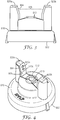
- FIG. 6 is a perspective view of an exemplary face geometry insert and FIG. 7 is a perspective view of the face geometry insert of FIG. 6 further comprising auxiliary air holes.
- Face geometry insert 104 is formed in a substantially flat configuration and has hinges 118a, 118b to permit shaping it to fit into a base member.
- the pairs of shaping air apertures 110a, 110b and 110c, 110d and the center frame opening 112 are aligned as a result of the mold design.
- Air flow surface 115 is shaped as desired.
- Optional auxiliary air holes 117 are located in the body of the face geometry insert 104.
- air jets exiting the auxiliary air holes interact with the shaping air jets to shape and refine the liquid spray further in addition to the air exiting a center air outlet, which is the annulus between the air flow surface 115 and the outside surface or diameter of a liquid nozzle port. Additionally, the forwardly projecting air jets from the auxiliary air holes help prevent or reduce the accumulation of spray on the air cap that can be caused by the impinging flows in front of the air cap.
- Location of the auxiliary air holes is not limited, but usually they are arranged symmetrically about the center frame 513 or center frame opening 512.
- FIG. 8 is a perspective view of another exemplary face geometry insert and FIG. 9 is a perspective view of the face geometry insert of FIG. 8 further comprising auxiliary air holes.
- Face geometry insert 504 may be formed in its final desired shape for fitting into a base member.
- the pairs of shaping air apertures 510a, 510b and 510c, 510d and the center frame opening 512 are aligned as a result of the mold design.
- Center frame 513 is present.
- Air flow surface 515 is shaped as desired.
- Capping features 520a, 520b facilitate assembly and/or registration of the face geometry insert 504 with respect to a base member.
- Optional auxiliary air holes 517 are located in the body of the face geometry insert 504.
- Air jets exiting the auxiliary air holes interact with the shaping air jets to shape and refine the liquid spray further in addition to the air exiting a center air outlet, which is the gap between the air flow surface 515 and the outside surface or diameter of a liquid nozzle port. Additionally, air jets from the auxiliary air holes help prevent or reduce the accumulation of spray on the air cap that can be caused by the turbulent air flow in front of the air cap.
- Location of the auxiliary air holes is not limited, but usually they are arranged symmetrically about the central frame opening.
- FIG. 10 provides a perspective view of another exemplary face geometry insert 204 which may be formed in its final desired shape without hinges for fitting into a base member.
- the pairs of shaping air apertures 210a, 210b and 210c, 210d and the center frame opening 212 are aligned as a result of the mold design.
- Center frame 213 is present.
- Air flow surface 215 is shaped as desired.
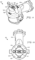
- FIG. 11 provides a perspective view of an exemplary spray head assembly
- FIG. 12 is a top view of FIG. 11
- FIG. 15 is a close up of FIG. 11
- Spray head assembly 301 has a barrel 330 to which the air cap 300 attaches.
- the air cap may have stops that limit rotation of the air cap on the barrel due to the presence of tabs or other such features on the barrel. This may permit rotation through a desired angle (e.g., 90 degrees) between first and second relative positions.
- the air cap 300 comprises face geometry insert 304 and base member 302.
- a liquid nozzle port 352 resides in the center frame opening (not numbered) defined by center frame 313.
- Air will flow through the annulus formed between the air flow surface 315 and the outside diameter 351 of the liquid nozzle port 352 during operation of a liquid spray gun.
- the air flow surface 315 may be designed in any angle, depth, shape, or otherwise to achieve a spray pattern suitable for a particular application.
- nozzle tips may be attached onto the liquid nozzle port 352 and/or face geometry insert 304.
- Exemplary nozzle tips are provided in WO2012/109298 , which are commonly assigned. Positioning of the pair of shaping air apertures, the center frame opening, and the nozzle tip may be effective to provide a refined spray pattern from the liquid spray gun.
- a nozzle tip 660 is attached to face geometry insert 604. Liquid nozzle port 652 is also shown.
- FIG. 17 shows an exploded perspective view of an air cap 600 and the face geometry insert 604 with the nozzle tip 600 attached.
- the face geometry insert 604 comprises a bridging portion 605, one or more pairs of air apertures (not numbered) and is retained to the base member 602.
- the face geometry insert 604 may also comprise a center frame 113 and its center frame opening (not numbered) has nozzle tip 660 and nozzle port 652 residing therein. Air flows through the annulus formed by air flow surface 615 and the outside diameter of liquid nozzle port 652.
- the base member 602 comprises at least one pair of exit air openings 607a, 607b, a base member body 616, and a nozzle tip opening 606. Air horns 608a and 608b are exemplified in FIG. 17 .
- FIG. 13 is a perspective view of the spray head assembly of FIG. 11 with the base member removed to show detail of the arrangement and position of the face geometry insert with respect to the liquid nozzle port of the barrel.
- Barrel 430 has a front wall 436 having openings 434, a fan air barrel passage 447, a liquid nozzle port 452, and liquid passageway 471.
- the face geometry insert 404 has shaping air apertures 410a, 410b (not shown), 410c, and 410d, center frame 413, and air flow surface 415. Liquid supplied by a reservoir of a spray gun travels through the liquid passageway 471 and out the liquid nozzle port 452.
- An air passageway from the spray gun supplies air through the openings 434 to a center air outlet (not numbered), which is the gap between the air flow surface 415 and the outside surface or diameter of the liquid nozzle port 452. Air also exits the shaping air apertures 410a, 410c, and 410d (aperture 410b is not shown) and the fan air barrel passage 447.
- the face geometry insert 404 permits the formation of a single molded piece that contains various exit openings whose sizes and positions can be precisely defined so that resulting spray patterns are reliably and consistently produced.
Landscapes
- Nozzles (AREA)
Applications Claiming Priority (2)
| Application Number | Priority Date | Filing Date | Title |
|---|---|---|---|
| US201361846309P | 2013-07-15 | 2013-07-15 | |
| PCT/US2014/045544 WO2015009475A1 (en) | 2013-07-15 | 2014-07-07 | Air caps with face geometry inserts for liquid spray guns |
Publications (2)
| Publication Number | Publication Date |
|---|---|
| EP3021982A1 EP3021982A1 (en) | 2016-05-25 |
| EP3021982B1 true EP3021982B1 (en) | 2020-02-26 |
Family
ID=51225090
Family Applications (1)
| Application Number | Title | Priority Date | Filing Date |
|---|---|---|---|
| EP14742701.7A Active EP3021982B1 (en) | 2013-07-15 | 2014-07-07 | Air caps with face geometry inserts for liquid spray guns |
Country Status (10)
| Country | Link |
|---|---|
| US (1) | US10493473B2 (enExample) |
| EP (1) | EP3021982B1 (enExample) |
| JP (1) | JP6449874B2 (enExample) |
| KR (1) | KR20160030989A (enExample) |
| CN (1) | CN105392568B (enExample) |
| AU (1) | AU2014290641B2 (enExample) |
| CA (1) | CA2918141A1 (enExample) |
| MX (1) | MX2016000552A (enExample) |
| RU (1) | RU2638399C2 (enExample) |
| WO (1) | WO2015009475A1 (enExample) |
Families Citing this family (15)
| Publication number | Priority date | Publication date | Assignee | Title |
|---|---|---|---|---|
| ES2620017T3 (es) | 2009-01-26 | 2017-06-27 | 3M Innovative Properties Company | Pistola pulverizadora de líquido, plataforma de pistola pulverizadora y unidad de cabezal de pulverización |
| CN103370139B (zh) | 2011-02-09 | 2017-09-05 | 3M创新有限公司 | 用于液体喷枪的喷嘴头和喷头组件 |
| CN103889586B (zh) | 2011-10-12 | 2016-10-12 | 3M创新有限公司 | 用于液体喷枪的喷雾头组件 |
| JP6185940B2 (ja) | 2012-03-06 | 2017-08-23 | スリーエム イノベイティブ プロパティズ カンパニー | 内部ブースト通路を有するスプレーガン |
| KR20190092421A (ko) | 2016-12-06 | 2019-08-07 | 쓰리엠 이노베이티브 프로퍼티즈 컴파니 | 스프레이 건 및 노즐 조립체 부착 |
| KR20190092420A (ko) | 2016-12-06 | 2019-08-07 | 쓰리엠 이노베이티브 프로퍼티즈 컴파니 | 스프레이 건 에어 캡 유지 수단 |
| WO2018104826A1 (en) | 2016-12-06 | 2018-06-14 | 3M Innovative Properties Company | Paint spray gun coating liquid connector |
| US11154884B2 (en) | 2016-12-12 | 2021-10-26 | 3M Innovative Properties Company | Spray gun and nozzle assembly attachment |
| US11154894B2 (en) | 2016-12-12 | 2021-10-26 | 3M Innovative Properties Company | Spray gun and nozzle assembly attachment |
| US11666934B2 (en) | 2016-12-12 | 2023-06-06 | 3M Innovative Properties Company | Spray gun and nozzle assembly attachment |
| USD913418S1 (en) * | 2018-07-10 | 2021-03-16 | Nordson Corporation | Powder spray gun component |
| USD891578S1 (en) * | 2019-04-05 | 2020-07-28 | Graco Minnesota Inc. | Electrostatic spray gun air cap |
| EP4019142A3 (en) | 2020-07-14 | 2022-09-14 | Techtronic Cordless GP | Powered sprayer |
| US20240295392A1 (en) * | 2023-03-03 | 2024-09-05 | Graco Minnesota Inc. | Alignment tool for a spray gun |
| USD1069044S1 (en) * | 2023-06-15 | 2025-04-01 | Graco Minnesota Inc. | Air cap |
Family Cites Families (229)
| Publication number | Priority date | Publication date | Assignee | Title |
|---|---|---|---|---|
| US1299290A (en) | 1916-04-21 | 1919-04-01 | Reidar Berg | Air-brush. |
| US1539536A (en) * | 1922-11-24 | 1925-05-26 | Peerless Pneumatic Systems Inc | Spray gun |
| US1748440A (en) * | 1925-03-30 | 1930-02-25 | Burdick Charles Laurence | Spraying apparatus |
| US2059706A (en) | 1931-07-16 | 1936-11-03 | Jens A Paasche | Air painting device |
| GB425382A (en) | 1933-11-30 | 1935-03-13 | Stanley Dewsnap Hill | Improvements in or relating to spraying nozzles |
| US2042746A (en) * | 1934-01-18 | 1936-06-02 | Vilbiss Co | Spray head |
| US2126888A (en) | 1936-05-26 | 1938-08-16 | Alexander F Jenkins | Spray gun nozzle |
| US2362946A (en) | 1940-07-31 | 1944-11-14 | Fmc Corp | Spray gun |
| US2303280A (en) * | 1940-09-09 | 1942-11-24 | Alexander F Jenkins | Spray gun |
| US2497625A (en) | 1944-08-03 | 1950-02-14 | Henrietta M Norwick | Spray gun |
| US2904262A (en) | 1954-11-04 | 1959-09-15 | Vilbiss Co | Spray gun |
| NL205691A (enExample) | 1955-03-30 | |||
| US2820670A (en) | 1956-04-13 | 1958-01-21 | Metallizing Engineering Co Inc | Valve arrangement for heat-fusible material spray guns |
| GB829370A (en) | 1956-04-13 | 1960-03-02 | Metallizing Engineering Co Inc | Improvements in or relating to heat-fusible material spray guns |
| US2991940A (en) * | 1957-07-11 | 1961-07-11 | Gen Motors Corp | Paint spray gun with detachable head |
| US3062453A (en) | 1959-07-14 | 1962-11-06 | Lucerne Products Inc | Spray gun |
| US5110011A (en) | 1990-06-29 | 1992-05-05 | Minnesota Mining And Manufacturing Company | Non-releasable spray head and dip tube assembly |
| US3168250A (en) * | 1961-11-24 | 1965-02-02 | Jens A Paasche | Airbrush mechanism |
| SU172206A1 (ru) | 1963-01-29 | 1965-07-26 | В. Ф. Попов | Пневматический пистолет-распылитель вязких жидкостей, красок и паст |
| US3157360A (en) | 1963-02-25 | 1964-11-17 | William L Heard | Spray gun having valved flexible liner |
| US3236459A (en) | 1963-12-16 | 1966-02-22 | Thomas P Mcritchie | Apparatus for spraying materials |
| US3270920A (en) | 1964-12-03 | 1966-09-06 | Charles G Nessler | Apparatus for pressure dispensing liquids |
| US3425625A (en) | 1967-08-11 | 1969-02-04 | Ramsburg Electro Coating Corp | Electrostatic spray device |
| US3515354A (en) | 1967-08-21 | 1970-06-02 | Donald R Presson | Spray nozzle |
| GB1293341A (en) | 1968-08-23 | 1972-10-18 | Power Sprays Ltd | Spray guns |
| US3623669A (en) | 1969-07-10 | 1971-11-30 | Billy L Woods | Spray gun |
| US3633828A (en) | 1970-01-19 | 1972-01-11 | Graco Inc | Spray gun |
| US3581998A (en) | 1970-07-29 | 1971-06-01 | Maurice F Roche | Soap dispensing means |
| FR2114289A5 (enExample) | 1970-11-18 | 1972-06-30 | Secmer Sa | |
| US3942680A (en) | 1973-07-31 | 1976-03-09 | Seeley Larry E | Spray paint container and attachment therefor |
| US3876150A (en) | 1973-10-24 | 1975-04-08 | Black & Decker Mfg Co | Paint spray nozzle |
| DE2653981C3 (de) | 1976-11-27 | 1979-08-16 | J. Wagner Gmbh, 7990 Friedrichshafen | Spritzpistole |
| IT1138756B (it) | 1980-04-29 | 1986-09-17 | Ihmels Manfred | Pistola a spruzzo azionata a pressione |
| DE3118207A1 (de) | 1981-05-08 | 1982-11-25 | Lang Apparatebau GmbH, 8227 Siegsdorf | "spruehgeraet" |
| US4392617A (en) | 1981-06-29 | 1983-07-12 | International Business Machines Corporation | Spray head apparatus |
| US4478370A (en) * | 1982-03-19 | 1984-10-23 | Nordson Corporation | Air atomizing nozzle assembly |
| US4537357A (en) | 1982-05-03 | 1985-08-27 | Binks Manufacturing Company | Spray guns |
| US4513913A (en) | 1982-11-10 | 1985-04-30 | Binks Manufacturing Company | Reversible airless spray nozzle |
| US4529126A (en) | 1983-03-14 | 1985-07-16 | Frank Ives | External mixing spray gun |
| DE3346165C2 (de) | 1983-12-21 | 1987-04-30 | Hartmut 2905 Edewecht Ihmels | Sprühmitteleinsatz für Sprühpistolen |
| US4660774A (en) | 1985-05-23 | 1987-04-28 | Graco Inc. | Fluid nozzle locking mechanism |
| US4615485A (en) | 1985-06-10 | 1986-10-07 | Graco Inc. | Paint circulation adapter and coupler |
| US4830281A (en) | 1985-08-16 | 1989-05-16 | Asm Corporation | Spray tip with seal ejector |
| US4657184A (en) | 1986-01-31 | 1987-04-14 | Champion Spark Plug Company | Fluid tip and air cap assembly |
| JPS6339448A (ja) | 1986-07-31 | 1988-02-19 | Fujitsu General Ltd | 電動機におけるロ−タ位置検出素子の取付装置 |
| US4712739A (en) | 1986-10-03 | 1987-12-15 | Champion Spark Plug Company | Spray gun nozzle assembly retainer clip and spray gun nozzle assembly |
| US4738401A (en) | 1987-02-24 | 1988-04-19 | Spraying Systems Co. | Quick disconnect nozzle assembly with twist-on spray tip |
| US4817872A (en) | 1987-05-22 | 1989-04-04 | Mattson Roy D | Adjustable fluid spray gun |
| US4815666A (en) | 1987-09-21 | 1989-03-28 | Nordson Corporation | Powder spray gun for quick color changes systems |
| US4993642A (en) | 1987-09-28 | 1991-02-19 | Accuspray, Inc. | Paint spray gun |
| US4760962A (en) | 1987-10-30 | 1988-08-02 | The Devilbiss Company | Spray gun paint cup and lid assembly |
| DE3815327C2 (de) | 1988-05-05 | 1996-11-07 | Rathor Ag | Vorrichtung zum Verarbeiten des Substrates von Druckdosen, insbesondere von Polyurethanschäumen |
| US4925101A (en) | 1988-08-26 | 1990-05-15 | Nordson Corporation | Wax spray gun and nozzle |
| US4971251A (en) | 1988-11-28 | 1990-11-20 | Minnesota Mining And Manufacturing Company | Spray gun with disposable liquid handling portion |
| DE3904437A1 (de) | 1989-02-14 | 1990-08-16 | Gema Ransburg Ag | Spruehpistole zum elektrostatischen spruehbeschichten |
| DE4027421A1 (de) | 1990-08-30 | 1992-03-05 | Bromhaar Marinus Johan Grootte | Handspritzgeraet |
| IT222968Z2 (it) | 1990-12-20 | 1995-05-12 | A N I Spa Off Mec | Struttura di tappo particolarmente per contenitori di liquidi nebulizzabili. |
| US5119992A (en) | 1991-02-11 | 1992-06-09 | Ransburg Corporation | Spray gun with regulated pressure feed paint cup |
| CA2039086A1 (en) | 1991-03-26 | 1992-09-27 | Thomas Barty | Spray gun nozzle head |
| US5209405A (en) | 1991-04-19 | 1993-05-11 | Ransburg Corporation | Baffle for hvlp paint spray gun |
| US5242115A (en) | 1991-04-22 | 1993-09-07 | Fomo Products, Inc. | Apparatus and method for mixing and dispensing and mixing nozzle therefore |
| US5178330A (en) | 1991-05-17 | 1993-01-12 | Ransburg Corporation | Electrostatic high voltage, low pressure paint spray gun |
| US5279461A (en) * | 1991-09-03 | 1994-01-18 | Apollo Sprayers International, Inc. | Spray gun |
| RU2014906C1 (ru) | 1992-01-27 | 1994-06-30 | Фирма "Коммерция-транспорт-комплекс" | Устройство для нанесения покрытий |
| JPH0734880B2 (ja) | 1992-02-03 | 1995-04-19 | 有限会社ミナリ | 塗装ガン |
| US5280853A (en) | 1992-10-15 | 1994-01-25 | Asm Company, Inc. | Single piece spray tip |
| US5322221A (en) | 1992-11-09 | 1994-06-21 | Graco Inc. | Air nozzle |
| JP2769962B2 (ja) * | 1993-04-21 | 1998-06-25 | アロイ工器株式会社 | 塗装に適する空気添加型噴霧装置 |
| US5344078A (en) * | 1993-04-22 | 1994-09-06 | Ransburg Corporation | Nozzle assembly for HVLP spray gun |
| US5332156A (en) | 1993-10-25 | 1994-07-26 | Ransburg Corporation | Spray gun with removable cover and method for securing a cover to a spray gun |
| US5395046A (en) | 1993-10-25 | 1995-03-07 | Nordson Corporation | Hand-held spray gun with replaceable handle |
| US5456414A (en) | 1993-10-28 | 1995-10-10 | Ransburg Corporation | Suction feed nozzle assembly for HVLP spray gun |
| US5474450A (en) | 1994-02-08 | 1995-12-12 | Chronister; Stephen H. | Dental instrument |
| JP2530574B2 (ja) | 1994-03-30 | 1996-09-04 | 旭サナック株式会社 | エア―スプレイガン用アタッチメント |
| US5454517A (en) | 1994-03-30 | 1995-10-03 | Naemura; William H. | Air brush with removable and rotatable nozzle head |
| CA2143277C (en) | 1994-04-19 | 2000-05-16 | Michael J. Kosmyna | Hand held paint spray gun with top mounted paint cup |
| DE4416939A1 (de) | 1994-05-13 | 1995-11-16 | Bruno Jesswein Kunststofftechn | Spritzpistole |
| DE9416015U1 (de) | 1994-10-05 | 1994-11-17 | Sata-Farbspritztechnik GmbH & Co., 70806 Kornwestheim | Düsenanordnung für eine Farbspritzpistole |
| GB9420375D0 (en) | 1994-10-10 | 1994-11-23 | Itw Ltd | An improved nozzle and aircap for spray guns |
| DE19503495A1 (de) | 1995-02-03 | 1996-08-08 | Amv Autom Montage Vertrieb Fa | Spritzpistole mit ansetzbaren Düsenelementen |
| US5609302A (en) | 1995-04-19 | 1997-03-11 | Smith; William C. | Removable spray gun fluid flow assembly |
| DE19605227A1 (de) | 1996-02-13 | 1997-08-14 | Hk Haag & Kurz Gmbh | Anschlußverbindung zwischen einer Spritzpistole und einem Ausgabeteil |
| JP3148646B2 (ja) | 1996-07-12 | 2001-03-19 | アネスト岩田株式会社 | 塗付材料循環供給型スプレーガン |
| US5765753A (en) | 1996-07-18 | 1998-06-16 | Wagner Spray Tech Corporation | Reversible spray tip |
| US5711421A (en) | 1996-09-12 | 1998-01-27 | Guo; Wen Li | Spray gun assembly |
| US6820824B1 (en) | 1998-01-14 | 2004-11-23 | 3M Innovative Properties Company | Apparatus for spraying liquids, disposable containers and liners suitable for use therewith |
| JPH10314628A (ja) | 1997-05-19 | 1998-12-02 | B B Ritsuchi:Kk | エアーブラシ |
| US6019294A (en) | 1997-05-23 | 2000-02-01 | Graco Inc | Interchangeable feed airspray/HVLP spray gun |
| JP3412746B2 (ja) | 1997-10-14 | 2003-06-03 | 株式会社ビービーリッチ | エアーブラシ |
| US20030071144A1 (en) | 1997-10-14 | 2003-04-17 | Naemura William H. | Air brush with removable and rotatable nozzle head |
| JPH11114458A (ja) | 1997-10-15 | 1999-04-27 | Mesakku:Kk | 塗装ガン |
| US6056213A (en) | 1998-01-30 | 2000-05-02 | 3M Innovative Properties Company | Modular system for atomizing a liquid |
| US6062493A (en) | 1998-02-26 | 2000-05-16 | Abplanalp; Robert Henry | Sprayer for liquids and nozzle insert |
| US6085996A (en) | 1998-03-05 | 2000-07-11 | Coating Atomization Technologies, Llc | Two-piece spray nozzle |
| JP2002506724A (ja) | 1998-03-17 | 2002-03-05 | マルセル・レイシ | スプレーヘッド |
| US6012651A (en) | 1998-04-10 | 2000-01-11 | Spitznagel; Max W. A. | Gravity-fed spray gun assembly |
| US6050504A (en) * | 1998-05-06 | 2000-04-18 | Emson, Inc. | Spray dispensing device using swirl passages and using the Bernoulli effect |
| US5979797A (en) | 1998-08-14 | 1999-11-09 | Castellano; Michael A. | Handheld pressurized hopper gun and method |
| US6460787B1 (en) | 1998-10-22 | 2002-10-08 | Nordson Corporation | Modular fluid spray gun |
| US6068203A (en) | 1999-02-04 | 2000-05-30 | Campbell Hausfeld/Scott Fetzer Company | Selective venting sprayer |
| US6098902A (en) | 1999-05-14 | 2000-08-08 | Coating Atomization Technologies, Llc | Spray gun for atomizing and applying liquid coatings having interchangeable nozzle assemblies |
| AU4394399A (en) | 1999-06-30 | 2001-01-22 | Anest Iwata Corporation | Low-pressure atomizing spray gun |
| CN1280885A (zh) | 1999-07-14 | 2001-01-24 | 李旺根 | 喷枪组 |
| US6536687B1 (en) | 1999-08-16 | 2003-03-25 | 3M Innovative Properties Company | Mixing cup adapting assembly |
| FR2797787B1 (fr) | 1999-08-30 | 2002-02-22 | Sames Sa | Dispositif de projection de produit de revetement comprenant au moins un projecteur et un reservoir a piston |
| USD429794S (en) | 1999-09-30 | 2000-08-22 | Griffin Llc | Sprayer collar |
| US6345776B1 (en) | 1999-12-23 | 2002-02-12 | Fomo Products Inc. | Two-component dispensing gun |
| US6520426B2 (en) * | 2000-01-26 | 2003-02-18 | Spraying Systems Co. | Sanitary spray nozzle for spray guns |
| US6702198B2 (en) | 2000-02-29 | 2004-03-09 | Graco Minnesota Inc. | Reversible airless spray tip assembly |
| US6375096B1 (en) | 2000-03-01 | 2002-04-23 | Cleveland State University | Two component spray gun and nozzle attachment |
| JP4450344B2 (ja) | 2000-06-26 | 2010-04-14 | 旭サナック株式会社 | 塗装用エアースプレイガン |
| CN2431971Y (zh) | 2000-07-05 | 2001-05-30 | 赵惠珍 | 快速更换喷水头的喷水枪 |
| US6450422B1 (en) | 2000-09-07 | 2002-09-17 | Richard A. Maggio | Spray gun |
| US6471144B1 (en) | 2000-10-23 | 2002-10-29 | Tiao-Hsiang Huang | Structure of spray gun air guide nozzle with dual pressure reduction |
| EP1201317B1 (fr) | 2000-10-24 | 2008-05-14 | L'oreal | Dispositif de pulvérisation comportant au moins deux orifices de sortie de gaz vecteur |
| US6685106B1 (en) | 2000-11-28 | 2004-02-03 | Efc Systems, Inc. | Paint spraying device |
| US6502763B1 (en) | 2001-01-17 | 2003-01-07 | American Spray Parts | Removable multiple orifice spray tip |
| GB2372465B (en) | 2001-02-26 | 2004-07-14 | Itw Ltd | A spray gun |
| US20030015604A1 (en) * | 2001-07-18 | 2003-01-23 | Kobayashi William Thoru | Nozzle to promote flat fluid stream |
| DE10135104C1 (de) * | 2001-07-19 | 2002-09-12 | Sata Farbspritztechnik | Farbspritzpistole |
| US6854667B2 (en) | 2001-09-06 | 2005-02-15 | Graco Minnesota Inc. | Spray gun having indexing air cap with quick release retaining ring |
| GB0122208D0 (en) * | 2001-09-14 | 2001-11-07 | Vincent Ltd G | Spray gun |
| JP3737731B2 (ja) | 2001-10-03 | 2006-01-25 | 株式会社明治機械製作所 | エアスプレーガン用の塗料ノズル金具、およびそれを用いたエアスプレーガン |
| US7083115B2 (en) * | 2001-10-04 | 2006-08-01 | Spraying Systems Co. | Spray gun with removable heat jacket |
| KR100435685B1 (ko) | 2001-10-23 | 2004-06-12 | 현대자동차주식회사 | 도장용 스프레이건 |
| US6543705B1 (en) | 2001-11-27 | 2003-04-08 | Chena Liao | Mold spray gun structure |
| SE524216C2 (sv) | 2001-12-14 | 2004-07-13 | Haakan Emilsson | Spruthuvud med konvext välvd frontsköld med luftmunstycken |
| US6764026B2 (en) | 2001-12-18 | 2004-07-20 | Bayer Polymers Llc | Process for spraying one-component compositions with air-assisted, low pressure equipment having an improved spray nozzle |
| DE10208861B4 (de) | 2002-03-01 | 2015-07-23 | J. Wagner Gmbh | Spritzpistole |
| US6793155B2 (en) * | 2002-03-14 | 2004-09-21 | Tiao-Hsiang Huang | Spray gun pressure stabilizer |
| FR2839663B1 (fr) | 2002-05-16 | 2004-07-23 | Itw Surfaces & Finitions | Tete de pulverisation d'un produit tel que de la peinture |
| US20050173561A1 (en) | 2002-05-28 | 2005-08-11 | John Cotter | Spray nozzle assembly |
| US20040089742A1 (en) | 2002-07-26 | 2004-05-13 | Antonucci Louis A. | Drywall texture gun |
| US6808122B2 (en) | 2002-08-19 | 2004-10-26 | Illinois Tool Works, Inc. | Spray gun with improved pre-atomization fluid mixing and breakup |
| US7762476B2 (en) * | 2002-08-19 | 2010-07-27 | Illinois Tool Works Inc. | Spray gun with improved atomization |
| US6874702B2 (en) | 2002-10-08 | 2005-04-05 | Micron Technology, Inc. | Modular spray gun apparatus and methods |
| US20060097070A1 (en) * | 2002-10-15 | 2006-05-11 | Spraying Systems Co. | External mix air assisted spray nozzle assembly |
| US6805306B1 (en) | 2002-10-23 | 2004-10-19 | Huang Jung-Kun | Cylinder rapid engagement device in an electrical spray gun |
| US6953155B2 (en) | 2002-10-24 | 2005-10-11 | 3M Innovative Properties Company | Pressure assisted liquid supply assembly |
| GB0224698D0 (en) | 2002-10-24 | 2002-12-04 | 3M Innovative Properties Co | Easy clean spray gun |
| GB0224697D0 (en) | 2002-10-24 | 2002-12-04 | 3M Innovative Properties Co | Easy clean spray gun |
| US7484676B2 (en) | 2002-10-24 | 2009-02-03 | 3M Innovative Properties Company | Easy clean spray gun |
| EP1808235B1 (de) | 2002-12-10 | 2012-02-29 | Martin Ruda | Spritzpistolenbecher mit wiederverschliessbarer Druckausgleichsöffnung |
| DE10315426A1 (de) | 2002-12-10 | 2004-06-24 | Martin Ruda | Spritzpistolenbecher und Verfahren zum Herstellen eines Deckels |
| US6601782B1 (en) | 2002-12-23 | 2003-08-05 | Plas-Pak Industries, Inc. | Disposable spray nozzle assembly |
| DE20319574U1 (de) | 2003-02-11 | 2004-05-13 | Zijad, Jakupović | Spritzpistole für dickflüssige Materien |
| NL1024774C1 (nl) | 2003-02-18 | 2004-03-22 | Rudolphus Johannes Cornelissen | Verfspuit voorzien van een verfbeker, alsmede verfbeker voor toepassing in de verfspuit. |
| US6935577B2 (en) | 2003-02-28 | 2005-08-30 | Illinois Tool Works Inc. | One-piece fluid nozzle |
| US20040195401A1 (en) * | 2003-02-28 | 2004-10-07 | Strong Christopher L. | Repeatable mounting unit for automatic spray device |
| US7837131B2 (en) | 2003-03-27 | 2010-11-23 | Spraying Systems Co. | Modular automatic spray gun manifold |
| WO2004087328A1 (en) | 2003-03-27 | 2004-10-14 | Spraying Systems Co. | Modular spray gun with multiple control modules |
| DE112004000284D2 (de) | 2003-04-03 | 2005-10-27 | Martin Ruda | Adapter und Verfahren zum Aufnehmen eines Spritzpistolenbechers |
| GB0307902D0 (en) | 2003-04-05 | 2003-05-14 | 3M Innovative Properties Co | Spray gun with rotatable reservoir |
| DE10323256A1 (de) | 2003-05-23 | 2004-12-16 | Walther Spritz- Und Lackiersysteme Gmbh | Spritzpistole |
| US20040245673A1 (en) | 2003-06-09 | 2004-12-09 | Allsop Robert J. | Wear components in powder coating system |
| DE102004027789B4 (de) | 2003-06-11 | 2011-12-08 | Martin Ruda | Austauschbare Lackiermittelleiteinrichtung und Spritzpistole |
| US7798061B2 (en) | 2003-07-24 | 2010-09-21 | Carolin Dilou | Portable airbrush with improved paint mechanism and stencil assembly |
| US20050045741A1 (en) | 2003-08-27 | 2005-03-03 | Brown Daniel P. | Nozzle spray tip |
| US20050035220A1 (en) | 2003-08-11 | 2005-02-17 | Brown Daniel P. | Multi-component fluid nozzle assembly with detachable nozzle spray tip |
| US7083119B2 (en) | 2003-09-25 | 2006-08-01 | 3M Innovative Properties Company | Security clip for spray gun connector |
| CN1859951B (zh) | 2003-10-22 | 2010-09-01 | 贸易联合公司 | 模块化的喷枪装置和方法 |
| US7396376B2 (en) | 2003-12-22 | 2008-07-08 | Donaldson Company, Inc. | Seal arrangement for filter element; filter element assembly; and, methods |
| US7032839B2 (en) | 2003-12-30 | 2006-04-25 | 3M Innovative Properties Company | Liquid spray gun with manually separable portions |
| US7201336B2 (en) | 2003-12-30 | 2007-04-10 | 3M Innovative Properties Company | Liquid spray gun with non-circular horn air outlet passageways and apertures |
| US6971590B2 (en) * | 2003-12-30 | 2005-12-06 | 3M Innovative Properties Company | Liquid spray gun with manually rotatable frictionally retained air cap |
| US7165732B2 (en) | 2004-01-16 | 2007-01-23 | Illinois Tool Works Inc. | Adapter assembly for a fluid supply assembly |
| JP2005211699A (ja) | 2004-01-27 | 2005-08-11 | Susumu Iwakura | スプレーガンのノズルチップ |
| TW200536612A (en) * | 2004-03-26 | 2005-11-16 | Graco Minnesota Inc | Air spray gun improvements in nozzle and aircap |
| US6860438B1 (en) | 2004-04-06 | 2005-03-01 | Tiao-Hsiang Huang | Spray gun |
| US7237727B2 (en) | 2004-04-13 | 2007-07-03 | Hsing-Tzu Wang | Paint spray gun |
| US20050242207A1 (en) * | 2004-05-03 | 2005-11-03 | Ramon Tejeda | Spray gun coupled with a quick connect ring nut and a spring-loaded air diverter and a method for assembling the same |
| DE102004044475B4 (de) | 2004-05-07 | 2008-10-16 | Bayerische Motoren Werke Aktiengesellschaft | Kupplungsstück |
| US7757972B2 (en) | 2004-06-03 | 2010-07-20 | Illinois Tool Works Inc. | Conversion adapter for a fluid supply assembly |
| US7883026B2 (en) | 2004-06-30 | 2011-02-08 | Illinois Tool Works Inc. | Fluid atomizing system and method |
| FR2872717B1 (fr) * | 2004-07-12 | 2006-09-15 | Itw Surfaces & Finitions Sa | Pistolet de pulverisation automatique comprenant un corps de pulverisation monte sur une embase d'alimentation |
| TWM275032U (en) * | 2004-07-23 | 2005-09-11 | Chia Chung Prec Ind Co Ltd | Head structure of jetting gun |
| GB0422388D0 (en) | 2004-10-08 | 2004-11-10 | 3M Innovative Properties Co | Locking ring for spray gun connector |
| EP1817112B1 (en) | 2004-11-12 | 2010-08-04 | MT Industries, Inc. | Electrostatic spray nozzle system |
| US20060102550A1 (en) | 2004-11-18 | 2006-05-18 | Joseph Stephen C P | Liquid supply and filter assembly |
| US20060202060A1 (en) * | 2004-12-06 | 2006-09-14 | Alexander Kevin L | Dispensing device handle assembly |
| US7410106B2 (en) | 2005-02-08 | 2008-08-12 | 3M Innovative Properties Company | Pressurized liquid supply assembly |
| NL1028575C2 (nl) | 2005-03-18 | 2006-09-20 | Emm Productions B V | Wegwerpbeker voor een verfspuit en verfspuit voorzien daarvan. |
| US7757973B2 (en) | 2005-04-04 | 2010-07-20 | Illinois Tool Works Inc. | Hand-held coating dispensing device |
| USD552715S1 (en) | 2005-07-28 | 2007-10-09 | Sata Gmbh & Co. Kg | Paint spray gun |
| DE102005038162A1 (de) | 2005-08-12 | 2007-02-15 | Kriesmair, Bernd, Dipl.-Ing. | Vorrichtung zum Aufsprühen von pigmentierten Flüssigkeiten |
| USD538886S1 (en) | 2005-08-23 | 2007-03-20 | Kuan Chang Co., Ltd. | Spray gun body |
| US7097118B1 (en) | 2005-09-15 | 2006-08-29 | Kuan Chang Co., Ltd. | Spray paint gun with shunt control |
| US20070095943A1 (en) | 2005-10-28 | 2007-05-03 | Turnbull William N | Liquid reservoir, and kit, spray assembly and method using same |
| JP2009515096A (ja) | 2005-11-09 | 2009-04-09 | ドナルドソン カンパニー,インコーポレイティド | フィルタエレメントのシール構造、フィルタエレメントアッセンブリ及び方法 |
| US7328853B2 (en) | 2005-11-09 | 2008-02-12 | Tritech Industries Inc. | Reversible spray tip unit |
| USD542375S1 (en) | 2005-11-30 | 2007-05-08 | 3M Innovative Properites Company | Spray gun platform mounting |
| USD542376S1 (en) | 2005-11-30 | 2007-05-08 | 3M Innovative Properties Company | Spray gun nozzle and air cap assembly |
| JP5026701B2 (ja) | 2005-12-28 | 2012-09-19 | 俊治 久田 | 塗装用スプレーガン |
| GB0605105D0 (en) | 2006-03-14 | 2006-04-26 | Bwi Plc | Spray gun heads |
| US8684281B2 (en) * | 2006-03-24 | 2014-04-01 | Finishing Brands Holdings Inc. | Spray device having removable hard coated tip |
| CN1827231A (zh) | 2006-03-31 | 2006-09-06 | 褚孟品 | 一种喷枪 |
| DE102007012989B4 (de) | 2006-04-18 | 2012-05-16 | Martin Ruda | Lösbare Lackiermittelleiteinrichtung |
| US20070262169A1 (en) | 2006-05-01 | 2007-11-15 | Chia Chung Precision Industrial Co., Ltd. | Spray head structure of a spray gun |
| US7891588B2 (en) | 2006-05-31 | 2011-02-22 | Wagner Spray Tech Corporation | Quick disconnect for wetted parts in a paint spray gun |
| KR200428831Y1 (ko) | 2006-07-26 | 2006-10-13 | 정점숙 | 분사기 |
| US20080078849A1 (en) | 2006-09-30 | 2008-04-03 | Fox Jeffrey D | Disposable spray gun cartridge |
| US20090121048A1 (en) | 2007-01-30 | 2009-05-14 | Shunji Noshima | Spray gun |
| DE102007053855A1 (de) | 2007-02-27 | 2008-09-04 | Martin Ruda | Farbspritzpistole mit einem Grundkörper, auswechselbare Farbleiteinrichtung und Anordnung aus einer Farbspritzpistole, einer auswechselbaren Farbleiteinrichtung und einem Farbspritzpistolenbecher |
| US20080272213A1 (en) | 2007-05-02 | 2008-11-06 | Ting Chin-Ming | Spray Gun |
| US7789327B2 (en) | 2007-05-31 | 2010-09-07 | Illinois Tool Works Inc. | Modular spray gun with replaceable components |
| US8360345B2 (en) | 2007-05-31 | 2013-01-29 | Micheli Paul R | Airless spray gun having overhead valve and removable head |
| US20090026288A1 (en) * | 2007-07-25 | 2009-01-29 | Hsien-Chao Shih | Double Atomization Paint Spray Gun |
| US7922107B2 (en) | 2007-07-25 | 2011-04-12 | Fox Jeffrey D | Spray gun with paint cartridge |
| USD572343S1 (en) | 2007-12-10 | 2008-07-01 | Kuan Chang Co., Ltd. | Spray gun head |
| US8313047B2 (en) | 2007-12-10 | 2012-11-20 | Micheli Paul R | Spray gun having adjustable handle |
| US8870097B2 (en) | 2008-05-12 | 2014-10-28 | Finishing Brands Holdings Inc. | Airless spray gun having a removable valve cartridge and protective insert |
| US8899501B2 (en) | 2008-07-23 | 2014-12-02 | Sata Gmbh & Co. Kg | Spray gun with paint cartridge |
| EP2177273A1 (en) * | 2008-10-16 | 2010-04-21 | Urea Casale S.A. | Spraying method and nozzle for atomization of a liquid |
| EP2181773A1 (de) | 2008-11-03 | 2010-05-05 | J. Wagner GmbH | Spritz-Vorrichtung |
| EP2189226B1 (de) | 2008-11-19 | 2013-09-11 | J. Wagner GmbH | Luftkappe mit separat ausgeformtem Luftrichter und deren Herstellungsverfahren mittels Spritzgießen |
| US7971806B2 (en) | 2008-12-30 | 2011-07-05 | Graco Minnesota Inc. | Poppet check valve for air-assisted spray gun |
| US8066205B2 (en) | 2008-12-30 | 2011-11-29 | Campbell Hausfeld/Scott Fetzer Company | Pressure-siphon switch for pneumatic spray gun |
| ES2620017T3 (es) * | 2009-01-26 | 2017-06-27 | 3M Innovative Properties Company | Pistola pulverizadora de líquido, plataforma de pistola pulverizadora y unidad de cabezal de pulverización |
| US7946510B2 (en) | 2009-02-19 | 2011-05-24 | Huang Jung-Kun | Nozzle assembly for spray guns |
| US8807454B2 (en) * | 2009-04-28 | 2014-08-19 | Finishing Brands Holdings Inc. | Methods and systems for delivering fluid through horns for applying multiple component material |
| USD616527S1 (en) * | 2009-09-18 | 2010-05-25 | Wagner Spray Tech Corporation | Spray gun |
| DE202010007355U1 (de) * | 2010-05-28 | 2011-10-20 | Sata Gmbh & Co. Kg | Düsenkopf für eine Spritzvorrichtung |
| CN103370139B (zh) | 2011-02-09 | 2017-09-05 | 3M创新有限公司 | 用于液体喷枪的喷嘴头和喷头组件 |
| DE202011050102U1 (de) | 2011-05-11 | 2011-08-01 | Kegham Armen | Spritzmittelleiteinrichtung für eine Spritzpistole sowie Spritzpistole mit einer Spritzmittelleiteinrichtung |
| ES2845618T3 (es) | 2011-07-28 | 2021-07-27 | 3M Innovative Properties Co | Unidad de cabezal de pulverización con tapón/boquilla para el aire integrado/a para una pistola pulverizadora de líquido |
| CN103889586B (zh) | 2011-10-12 | 2016-10-12 | 3M创新有限公司 | 用于液体喷枪的喷雾头组件 |
| JP6185940B2 (ja) | 2012-03-06 | 2017-08-23 | スリーエム イノベイティブ プロパティズ カンパニー | 内部ブースト通路を有するスプレーガン |
| US9302278B2 (en) * | 2014-05-29 | 2016-04-05 | Tsung Mao Industrial Co., Ltd. | Nozzle of spray gun |
| CA159961S (en) * | 2014-07-31 | 2015-07-17 | Sata Gmbh & Co Kg | Spray gun |
-
2014
- 2014-07-07 US US14/904,234 patent/US10493473B2/en active Active
- 2014-07-07 AU AU2014290641A patent/AU2014290641B2/en not_active Ceased
- 2014-07-07 CN CN201480039944.8A patent/CN105392568B/zh active Active
- 2014-07-07 CA CA2918141A patent/CA2918141A1/en not_active Abandoned
- 2014-07-07 MX MX2016000552A patent/MX2016000552A/es unknown
- 2014-07-07 JP JP2016526974A patent/JP6449874B2/ja active Active
- 2014-07-07 WO PCT/US2014/045544 patent/WO2015009475A1/en not_active Ceased
- 2014-07-07 RU RU2016101015A patent/RU2638399C2/ru not_active IP Right Cessation
- 2014-07-07 KR KR1020167003587A patent/KR20160030989A/ko not_active Withdrawn
- 2014-07-07 EP EP14742701.7A patent/EP3021982B1/en active Active
Non-Patent Citations (1)
| Title |
|---|
| None * |
Also Published As
| Publication number | Publication date |
|---|---|
| CA2918141A1 (en) | 2015-01-22 |
| US10493473B2 (en) | 2019-12-03 |
| WO2015009475A1 (en) | 2015-01-22 |
| JP2016525011A (ja) | 2016-08-22 |
| AU2014290641A1 (en) | 2016-02-11 |
| RU2638399C2 (ru) | 2017-12-13 |
| US20160151797A1 (en) | 2016-06-02 |
| MX2016000552A (es) | 2016-04-11 |
| CN105392568A (zh) | 2016-03-09 |
| CN105392568B (zh) | 2018-02-13 |
| KR20160030989A (ko) | 2016-03-21 |
| JP6449874B2 (ja) | 2019-01-09 |
| EP3021982A1 (en) | 2016-05-25 |
| RU2016101015A (ru) | 2017-08-18 |
| AU2014290641B2 (en) | 2017-07-06 |
Similar Documents
| Publication | Publication Date | Title |
|---|---|---|
| EP3021982B1 (en) | Air caps with face geometry inserts for liquid spray guns | |
| EP2673094B1 (en) | Nozzle tips and spray head assemblies for liquid spray guns | |
| EP3797873B1 (en) | Spray head assembly with integrated air cap/nozzle for a liquid spray gun | |
| EP4234102B1 (en) | Atomiser and showerhead | |
| CN106944279B (zh) | 用于喷枪的空气帽和喷嘴组件以及喷枪 | |
| DK2879805T3 (en) | nozzle arrangement | |
| CN107660163B (zh) | 具有辅助开孔的喷嘴组件 | |
| JP2018515336A5 (enExample) | ||
| WO2012127647A1 (ja) | ノズルの先端部材及びそれを用いたノズル | |
| US20230405618A1 (en) | Device for spraying media on the inner sides of medical products | |
| CN105579146B (zh) | 涂装装置及涂装方法 | |
| AU2012286837B2 (en) | Spray head assembly with integrated air cap/nozzle for a liquid spray gun | |
| JP2004255224A (ja) | 霧化式スプレーガン |
Legal Events
| Date | Code | Title | Description |
|---|---|---|---|
| PUAI | Public reference made under article 153(3) epc to a published international application that has entered the european phase |
Free format text: ORIGINAL CODE: 0009012 |
|
| 17P | Request for examination filed |
Effective date: 20160113 |
|
| AK | Designated contracting states |
Kind code of ref document: A1 Designated state(s): AL AT BE BG CH CY CZ DE DK EE ES FI FR GB GR HR HU IE IS IT LI LT LU LV MC MK MT NL NO PL PT RO RS SE SI SK SM TR |
|
| AX | Request for extension of the european patent |
Extension state: BA ME |
|
| DAX | Request for extension of the european patent (deleted) | ||
| GRAP | Despatch of communication of intention to grant a patent |
Free format text: ORIGINAL CODE: EPIDOSNIGR1 |
|
| STAA | Information on the status of an ep patent application or granted ep patent |
Free format text: STATUS: GRANT OF PATENT IS INTENDED |
|
| RIC1 | Information provided on ipc code assigned before grant |
Ipc: B05B 7/08 20060101AFI20190307BHEP Ipc: B05B 7/06 20060101ALI20190307BHEP |
|
| INTG | Intention to grant announced |
Effective date: 20190409 |
|
| GRAS | Grant fee paid |
Free format text: ORIGINAL CODE: EPIDOSNIGR3 |
|
| GRAJ | Information related to disapproval of communication of intention to grant by the applicant or resumption of examination proceedings by the epo deleted |
Free format text: ORIGINAL CODE: EPIDOSDIGR1 |
|
| GRAL | Information related to payment of fee for publishing/printing deleted |
Free format text: ORIGINAL CODE: EPIDOSDIGR3 |
|
| STAA | Information on the status of an ep patent application or granted ep patent |
Free format text: STATUS: REQUEST FOR EXAMINATION WAS MADE |
|
| GRAP | Despatch of communication of intention to grant a patent |
Free format text: ORIGINAL CODE: EPIDOSNIGR1 |
|
| STAA | Information on the status of an ep patent application or granted ep patent |
Free format text: STATUS: GRANT OF PATENT IS INTENDED |
|
| INTC | Intention to grant announced (deleted) | ||
| INTG | Intention to grant announced |
Effective date: 20190905 |
|
| RIN1 | Information on inventor provided before grant (corrected) |
Inventor name: QIBLAWI, JAMEEL R. Inventor name: SCHEIBNER, JOHN B. Inventor name: JOSEPH, STEPHEN C. P. |
|
| GRAA | (expected) grant |
Free format text: ORIGINAL CODE: 0009210 |
|
| STAA | Information on the status of an ep patent application or granted ep patent |
Free format text: STATUS: THE PATENT HAS BEEN GRANTED |
|
| AK | Designated contracting states |
Kind code of ref document: B1 Designated state(s): AL AT BE BG CH CY CZ DE DK EE ES FI FR GB GR HR HU IE IS IT LI LT LU LV MC MK MT NL NO PL PT RO RS SE SI SK SM TR |
|
| REG | Reference to a national code |
Ref country code: GB Ref legal event code: FG4D |
|
| REG | Reference to a national code |
Ref country code: CH Ref legal event code: EP |
|
| REG | Reference to a national code |
Ref country code: AT Ref legal event code: REF Ref document number: 1236991 Country of ref document: AT Kind code of ref document: T Effective date: 20200315 |
|
| REG | Reference to a national code |
Ref country code: IE Ref legal event code: FG4D |
|
| REG | Reference to a national code |
Ref country code: DE Ref legal event code: R096 Ref document number: 602014061517 Country of ref document: DE |
|
| PG25 | Lapsed in a contracting state [announced via postgrant information from national office to epo] |
Ref country code: FI Free format text: LAPSE BECAUSE OF FAILURE TO SUBMIT A TRANSLATION OF THE DESCRIPTION OR TO PAY THE FEE WITHIN THE PRESCRIBED TIME-LIMIT Effective date: 20200226 Ref country code: RS Free format text: LAPSE BECAUSE OF FAILURE TO SUBMIT A TRANSLATION OF THE DESCRIPTION OR TO PAY THE FEE WITHIN THE PRESCRIBED TIME-LIMIT Effective date: 20200226 Ref country code: NO Free format text: LAPSE BECAUSE OF FAILURE TO SUBMIT A TRANSLATION OF THE DESCRIPTION OR TO PAY THE FEE WITHIN THE PRESCRIBED TIME-LIMIT Effective date: 20200526 |
|
| REG | Reference to a national code |
Ref country code: NL Ref legal event code: MP Effective date: 20200226 |
|
| REG | Reference to a national code |
Ref country code: LT Ref legal event code: MG4D |
|
| PG25 | Lapsed in a contracting state [announced via postgrant information from national office to epo] |
Ref country code: HR Free format text: LAPSE BECAUSE OF FAILURE TO SUBMIT A TRANSLATION OF THE DESCRIPTION OR TO PAY THE FEE WITHIN THE PRESCRIBED TIME-LIMIT Effective date: 20200226 Ref country code: IS Free format text: LAPSE BECAUSE OF FAILURE TO SUBMIT A TRANSLATION OF THE DESCRIPTION OR TO PAY THE FEE WITHIN THE PRESCRIBED TIME-LIMIT Effective date: 20200626 Ref country code: GR Free format text: LAPSE BECAUSE OF FAILURE TO SUBMIT A TRANSLATION OF THE DESCRIPTION OR TO PAY THE FEE WITHIN THE PRESCRIBED TIME-LIMIT Effective date: 20200527 Ref country code: LV Free format text: LAPSE BECAUSE OF FAILURE TO SUBMIT A TRANSLATION OF THE DESCRIPTION OR TO PAY THE FEE WITHIN THE PRESCRIBED TIME-LIMIT Effective date: 20200226 Ref country code: SE Free format text: LAPSE BECAUSE OF FAILURE TO SUBMIT A TRANSLATION OF THE DESCRIPTION OR TO PAY THE FEE WITHIN THE PRESCRIBED TIME-LIMIT Effective date: 20200226 Ref country code: BG Free format text: LAPSE BECAUSE OF FAILURE TO SUBMIT A TRANSLATION OF THE DESCRIPTION OR TO PAY THE FEE WITHIN THE PRESCRIBED TIME-LIMIT Effective date: 20200526 |
|
| PG25 | Lapsed in a contracting state [announced via postgrant information from national office to epo] |
Ref country code: NL Free format text: LAPSE BECAUSE OF FAILURE TO SUBMIT A TRANSLATION OF THE DESCRIPTION OR TO PAY THE FEE WITHIN THE PRESCRIBED TIME-LIMIT Effective date: 20200226 |
|
| PG25 | Lapsed in a contracting state [announced via postgrant information from national office to epo] |
Ref country code: CZ Free format text: LAPSE BECAUSE OF FAILURE TO SUBMIT A TRANSLATION OF THE DESCRIPTION OR TO PAY THE FEE WITHIN THE PRESCRIBED TIME-LIMIT Effective date: 20200226 Ref country code: RO Free format text: LAPSE BECAUSE OF FAILURE TO SUBMIT A TRANSLATION OF THE DESCRIPTION OR TO PAY THE FEE WITHIN THE PRESCRIBED TIME-LIMIT Effective date: 20200226 Ref country code: SK Free format text: LAPSE BECAUSE OF FAILURE TO SUBMIT A TRANSLATION OF THE DESCRIPTION OR TO PAY THE FEE WITHIN THE PRESCRIBED TIME-LIMIT Effective date: 20200226 Ref country code: ES Free format text: LAPSE BECAUSE OF FAILURE TO SUBMIT A TRANSLATION OF THE DESCRIPTION OR TO PAY THE FEE WITHIN THE PRESCRIBED TIME-LIMIT Effective date: 20200226 Ref country code: PT Free format text: LAPSE BECAUSE OF FAILURE TO SUBMIT A TRANSLATION OF THE DESCRIPTION OR TO PAY THE FEE WITHIN THE PRESCRIBED TIME-LIMIT Effective date: 20200719 Ref country code: LT Free format text: LAPSE BECAUSE OF FAILURE TO SUBMIT A TRANSLATION OF THE DESCRIPTION OR TO PAY THE FEE WITHIN THE PRESCRIBED TIME-LIMIT Effective date: 20200226 Ref country code: EE Free format text: LAPSE BECAUSE OF FAILURE TO SUBMIT A TRANSLATION OF THE DESCRIPTION OR TO PAY THE FEE WITHIN THE PRESCRIBED TIME-LIMIT Effective date: 20200226 Ref country code: SM Free format text: LAPSE BECAUSE OF FAILURE TO SUBMIT A TRANSLATION OF THE DESCRIPTION OR TO PAY THE FEE WITHIN THE PRESCRIBED TIME-LIMIT Effective date: 20200226 Ref country code: DK Free format text: LAPSE BECAUSE OF FAILURE TO SUBMIT A TRANSLATION OF THE DESCRIPTION OR TO PAY THE FEE WITHIN THE PRESCRIBED TIME-LIMIT Effective date: 20200226 |
|
| REG | Reference to a national code |
Ref country code: AT Ref legal event code: MK05 Ref document number: 1236991 Country of ref document: AT Kind code of ref document: T Effective date: 20200226 |
|
| REG | Reference to a national code |
Ref country code: DE Ref legal event code: R097 Ref document number: 602014061517 Country of ref document: DE |
|
| PLBE | No opposition filed within time limit |
Free format text: ORIGINAL CODE: 0009261 |
|
| STAA | Information on the status of an ep patent application or granted ep patent |
Free format text: STATUS: NO OPPOSITION FILED WITHIN TIME LIMIT |
|
| PG25 | Lapsed in a contracting state [announced via postgrant information from national office to epo] |
Ref country code: IT Free format text: LAPSE BECAUSE OF FAILURE TO SUBMIT A TRANSLATION OF THE DESCRIPTION OR TO PAY THE FEE WITHIN THE PRESCRIBED TIME-LIMIT Effective date: 20200226 Ref country code: AT Free format text: LAPSE BECAUSE OF FAILURE TO SUBMIT A TRANSLATION OF THE DESCRIPTION OR TO PAY THE FEE WITHIN THE PRESCRIBED TIME-LIMIT Effective date: 20200226 |
|
| 26N | No opposition filed |
Effective date: 20201127 |
|
| PG25 | Lapsed in a contracting state [announced via postgrant information from national office to epo] |
Ref country code: SI Free format text: LAPSE BECAUSE OF FAILURE TO SUBMIT A TRANSLATION OF THE DESCRIPTION OR TO PAY THE FEE WITHIN THE PRESCRIBED TIME-LIMIT Effective date: 20200226 Ref country code: PL Free format text: LAPSE BECAUSE OF FAILURE TO SUBMIT A TRANSLATION OF THE DESCRIPTION OR TO PAY THE FEE WITHIN THE PRESCRIBED TIME-LIMIT Effective date: 20200226 Ref country code: MC Free format text: LAPSE BECAUSE OF FAILURE TO SUBMIT A TRANSLATION OF THE DESCRIPTION OR TO PAY THE FEE WITHIN THE PRESCRIBED TIME-LIMIT Effective date: 20200226 |
|
| REG | Reference to a national code |
Ref country code: CH Ref legal event code: PL |
|
| GBPC | Gb: european patent ceased through non-payment of renewal fee |
Effective date: 20200707 |
|
| REG | Reference to a national code |
Ref country code: BE Ref legal event code: MM Effective date: 20200731 |
|
| PG25 | Lapsed in a contracting state [announced via postgrant information from national office to epo] |
Ref country code: LU Free format text: LAPSE BECAUSE OF NON-PAYMENT OF DUE FEES Effective date: 20200707 Ref country code: FR Free format text: LAPSE BECAUSE OF NON-PAYMENT OF DUE FEES Effective date: 20200731 Ref country code: CH Free format text: LAPSE BECAUSE OF NON-PAYMENT OF DUE FEES Effective date: 20200731 Ref country code: LI Free format text: LAPSE BECAUSE OF NON-PAYMENT OF DUE FEES Effective date: 20200731 Ref country code: GB Free format text: LAPSE BECAUSE OF NON-PAYMENT OF DUE FEES Effective date: 20200707 Ref country code: IE Free format text: LAPSE BECAUSE OF NON-PAYMENT OF DUE FEES Effective date: 20200707 |
|
| PG25 | Lapsed in a contracting state [announced via postgrant information from national office to epo] |
Ref country code: BE Free format text: LAPSE BECAUSE OF NON-PAYMENT OF DUE FEES Effective date: 20200731 |
|
| PG25 | Lapsed in a contracting state [announced via postgrant information from national office to epo] |
Ref country code: TR Free format text: LAPSE BECAUSE OF FAILURE TO SUBMIT A TRANSLATION OF THE DESCRIPTION OR TO PAY THE FEE WITHIN THE PRESCRIBED TIME-LIMIT Effective date: 20200226 Ref country code: MT Free format text: LAPSE BECAUSE OF FAILURE TO SUBMIT A TRANSLATION OF THE DESCRIPTION OR TO PAY THE FEE WITHIN THE PRESCRIBED TIME-LIMIT Effective date: 20200226 Ref country code: CY Free format text: LAPSE BECAUSE OF FAILURE TO SUBMIT A TRANSLATION OF THE DESCRIPTION OR TO PAY THE FEE WITHIN THE PRESCRIBED TIME-LIMIT Effective date: 20200226 |
|
| PG25 | Lapsed in a contracting state [announced via postgrant information from national office to epo] |
Ref country code: MK Free format text: LAPSE BECAUSE OF FAILURE TO SUBMIT A TRANSLATION OF THE DESCRIPTION OR TO PAY THE FEE WITHIN THE PRESCRIBED TIME-LIMIT Effective date: 20200226 Ref country code: AL Free format text: LAPSE BECAUSE OF FAILURE TO SUBMIT A TRANSLATION OF THE DESCRIPTION OR TO PAY THE FEE WITHIN THE PRESCRIBED TIME-LIMIT Effective date: 20200226 |
|
| P01 | Opt-out of the competence of the unified patent court (upc) registered |
Effective date: 20230530 |
|
| PGFP | Annual fee paid to national office [announced via postgrant information from national office to epo] |
Ref country code: DE Payment date: 20250620 Year of fee payment: 12 |