US10493473B2 - Air caps with face geometry inserts for liquid spray guns - Google Patents
Air caps with face geometry inserts for liquid spray guns Download PDFInfo
- Publication number
- US10493473B2 US10493473B2 US14/904,234 US201414904234A US10493473B2 US 10493473 B2 US10493473 B2 US 10493473B2 US 201414904234 A US201414904234 A US 201414904234A US 10493473 B2 US10493473 B2 US 10493473B2
- Authority
- US
- United States
- Prior art keywords
- air
- face geometry
- base member
- air cap
- geometry insert
- Prior art date
- Legal status (The legal status is an assumption and is not a legal conclusion. Google has not performed a legal analysis and makes no representation as to the accuracy of the status listed.)
- Active, expires
Links
Images


Classifications
-
- B—PERFORMING OPERATIONS; TRANSPORTING
- B05—SPRAYING OR ATOMISING IN GENERAL; APPLYING FLUENT MATERIALS TO SURFACES, IN GENERAL
- B05B—SPRAYING APPARATUS; ATOMISING APPARATUS; NOZZLES
- B05B7/00—Spraying apparatus for discharge of liquids or other fluent materials from two or more sources, e.g. of liquid and air, of powder and gas
- B05B7/02—Spray pistols; Apparatus for discharge
- B05B7/08—Spray pistols; Apparatus for discharge with separate outlet orifices, e.g. to form parallel jets, i.e. the axis of the jets being parallel, to form intersecting jets, i.e. the axis of the jets converging but not necessarily intersecting at a point
- B05B7/0807—Spray pistols; Apparatus for discharge with separate outlet orifices, e.g. to form parallel jets, i.e. the axis of the jets being parallel, to form intersecting jets, i.e. the axis of the jets converging but not necessarily intersecting at a point to form intersecting jets
- B05B7/0815—Spray pistols; Apparatus for discharge with separate outlet orifices, e.g. to form parallel jets, i.e. the axis of the jets being parallel, to form intersecting jets, i.e. the axis of the jets converging but not necessarily intersecting at a point to form intersecting jets with at least one gas jet intersecting a jet constituted by a liquid or a mixture containing a liquid for controlling the shape of the latter
-
- B—PERFORMING OPERATIONS; TRANSPORTING
- B05—SPRAYING OR ATOMISING IN GENERAL; APPLYING FLUENT MATERIALS TO SURFACES, IN GENERAL
- B05B—SPRAYING APPARATUS; ATOMISING APPARATUS; NOZZLES
- B05B7/00—Spraying apparatus for discharge of liquids or other fluent materials from two or more sources, e.g. of liquid and air, of powder and gas
- B05B7/02—Spray pistols; Apparatus for discharge
- B05B7/06—Spray pistols; Apparatus for discharge with at least one outlet orifice surrounding another approximately in the same plane
- B05B7/062—Spray pistols; Apparatus for discharge with at least one outlet orifice surrounding another approximately in the same plane with only one liquid outlet and at least one gas outlet
- B05B7/066—Spray pistols; Apparatus for discharge with at least one outlet orifice surrounding another approximately in the same plane with only one liquid outlet and at least one gas outlet with an inner liquid outlet surrounded by at least one annular gas outlet
-
- B—PERFORMING OPERATIONS; TRANSPORTING
- B05—SPRAYING OR ATOMISING IN GENERAL; APPLYING FLUENT MATERIALS TO SURFACES, IN GENERAL
- B05B—SPRAYING APPARATUS; ATOMISING APPARATUS; NOZZLES
- B05B7/00—Spraying apparatus for discharge of liquids or other fluent materials from two or more sources, e.g. of liquid and air, of powder and gas
- B05B7/02—Spray pistols; Apparatus for discharge
- B05B7/08—Spray pistols; Apparatus for discharge with separate outlet orifices, e.g. to form parallel jets, i.e. the axis of the jets being parallel, to form intersecting jets, i.e. the axis of the jets converging but not necessarily intersecting at a point
- B05B7/0807—Spray pistols; Apparatus for discharge with separate outlet orifices, e.g. to form parallel jets, i.e. the axis of the jets being parallel, to form intersecting jets, i.e. the axis of the jets converging but not necessarily intersecting at a point to form intersecting jets
- B05B7/0861—Spray pistols; Apparatus for discharge with separate outlet orifices, e.g. to form parallel jets, i.e. the axis of the jets being parallel, to form intersecting jets, i.e. the axis of the jets converging but not necessarily intersecting at a point to form intersecting jets with one single jet constituted by a liquid or a mixture containing a liquid and several gas jets
-
- B—PERFORMING OPERATIONS; TRANSPORTING
- B05—SPRAYING OR ATOMISING IN GENERAL; APPLYING FLUENT MATERIALS TO SURFACES, IN GENERAL
- B05B—SPRAYING APPARATUS; ATOMISING APPARATUS; NOZZLES
- B05B7/00—Spraying apparatus for discharge of liquids or other fluent materials from two or more sources, e.g. of liquid and air, of powder and gas
- B05B7/02—Spray pistols; Apparatus for discharge
- B05B7/08—Spray pistols; Apparatus for discharge with separate outlet orifices, e.g. to form parallel jets, i.e. the axis of the jets being parallel, to form intersecting jets, i.e. the axis of the jets converging but not necessarily intersecting at a point
- B05B7/0807—Spray pistols; Apparatus for discharge with separate outlet orifices, e.g. to form parallel jets, i.e. the axis of the jets being parallel, to form intersecting jets, i.e. the axis of the jets converging but not necessarily intersecting at a point to form intersecting jets
- B05B7/0815—Spray pistols; Apparatus for discharge with separate outlet orifices, e.g. to form parallel jets, i.e. the axis of the jets being parallel, to form intersecting jets, i.e. the axis of the jets converging but not necessarily intersecting at a point to form intersecting jets with at least one gas jet intersecting a jet constituted by a liquid or a mixture containing a liquid for controlling the shape of the latter
- B05B7/0838—Spray pistols; Apparatus for discharge with separate outlet orifices, e.g. to form parallel jets, i.e. the axis of the jets being parallel, to form intersecting jets, i.e. the axis of the jets converging but not necessarily intersecting at a point to form intersecting jets with at least one gas jet intersecting a jet constituted by a liquid or a mixture containing a liquid for controlling the shape of the latter comprising a single means controlling simultaneously the flow rates of shaping and spraying gas jets
Definitions
- This disclosure relates to air caps for liquid spray head assemblies and/or for liquid spray guns.
- molded air caps with face geometry inserts are molded air caps with face geometry inserts. Face geometry inserts provided herein may be effective to provide symmetrical and balanced spray patterns.
- Spray guns are known for use in the application of liquids such as paints (and other coatings) across many industries.
- Such spray guns commonly include a gun body, a trigger, a spray head assembly, a reservoir for holding a liquid to be sprayed, and an air source to assist in atomizing and propelling the liquid onto a surface to be coated.
- the liquid may accumulate on the exterior and interior surfaces of the spray guns.
- spray guns were fabricated from metal and for a long-use life, which included reuse after cleaning and/or maintenance.
- face geometry inserts In order to address ensuring individual parts fabricated for spray guns are aligned to deliver desired spray patterns, face geometry inserts have been developed. Specifically provided herein are molded air caps with face geometry inserts for use with liquid spray head assemblies and/or for liquid spray guns.
- air caps for a liquid spray gun comprising: a base member comprising: a base member body, at least one pair of exit air openings, and a nozzle tip opening; and a face geometry insert comprising a bridging portion and a pair of shaping air apertures and being retained to the base member body; wherein each aperture of the pair of shaping air apertures is located on an opposite side of a spray axis of the air cap.
- Each aperture of the pair of shaping air apertures may be symmetric with respect to the spray axis.
- the face geometry insert may further comprise a center frame opening such that the center frame opening is concentric with the nozzle tip opening.
- the face geometry insert may further comprise at least one pair of capping features.
- the base member may further comprise at least one pair of capping features.
- the face geometry insert may further comprise at least one pair of auxiliary air holes.
- the base member may further comprise at least one pair of air horns that have the at least one pair of exit air openings.
- the face geometry insert may comprise at least one hinge. Or, the face geometry insert may comprise a non-planar body and no hinges.
- the face geometry insert is removable from the base member body.
- the face geometry insert may snap-fit into the base member body.
- the face geometry insert may bend-fit into the base member body.
- the face geometry insert is welded to the base member body.
- All embodiments may further comprise a nozzle tip affixed to the face geometry insert.
- the nozzle tip may be removably affixed to the center frame of the face geometry insert.
- the nozzle tip may be integral to the face geometry insert.
- An included angle ⁇ with respect to the relation among the spray axis and a plane of each surface of the pair of shaping air apertures is in the range of 25° to 85°.
- kits comprising a plurality of air caps as disclosed herein with one or more features of various sizes.
- the pairs of shaping air apertures of at least two of the face geometry inserts may have different configurations and/or the center frame openings of at least two of the face geometry inserts may have different dimensions and/or nozzle tips of different dimensions may be included.
- Another aspect is a spray head assembly for attachment to a liquid spray gun, the spray head assembly comprising a barrel and any of the air caps disclosed herein along with a nozzle tip.
- Liquid spray guns are also provided, which comprise: spray head assembly as disclosed herein assembled with a liquid spray gun body.
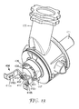
- FIG. 1 is an exploded perspective view of an air cap according to an embodiment
- FIG. 2 is an exploded perspective view of an air cap according to another embodiment
- FIG. 3 is a side view of the air cap of FIG. 2 ;
- FIG. 4 is a perspective view of the air cap of FIG. 2 ;
- FIG. 5 is a cross-section view of the air cap of FIG. 2 ;
- FIG. 6 is a perspective view of an exemplary face geometry insert
- FIG. 7 is a perspective view of the face geometry insert of FIG. 6 further comprising auxiliary air holes;
- FIG. 8 is a perspective view of another exemplary face geometry insert
- FIG. 9 is a perspective view of the face geometry insert of FIG. 8 further comprising auxiliary air holes;
- FIG. 10 is a perspective view of another exemplary face geometry insert
- FIG. 11 is a perspective view of an exemplary spray head assembly
- FIG. 12 is a top view of the spray head assembly of FIG. 11 ;
- FIG. 13 is a perspective view of the spray head assembly of FIG. 11 with the base member removed to show detail of the barrel and face member insert 404 ;
- FIG. 14 is a version of the air cap of FIG. 5 with markings to show an exemplary alignment of features
- FIG. 15 is a close-up of FIG. 11 ;
- FIG. 16 is a perspective view of another exemplary face geometry insert with a nozzle tip attached.
- FIG. 17 is an exploded perspective view of an air cap according to an embodiment where a nozzle tip is attached to a face geometry insert.
- air caps for liquid spray head assemblies and/or for liquid spray guns are provided.
- molded air caps with face geometry inserts are effective to provide a refined spray pattern, which is a spray pattern suitable for a desired application that is balanced, symmetrical, and has smooth transitions in coating spray density within the pattern. For smooth transitions, there are no excessively sharp changes in coating amount/density.
- current methods used to manufacture these components may involve casting or machining where creating pathways for air and/or liquid flow, and in particular for atomization, usually requires using labor and/or capitol intensive secondary operations, such as precision drilling. The secondary operations are susceptible to variations in the size and positioning of critical air outlets.
- the face geometry inserts are components wherein the location, size, and spacing of critical air and/or liquid openings are already aligned/designed into a single piece
- a face geometry insert is retained to a base member to form an air cap.
- the base member may be the larger of the two pieces, and it is fabricated easily as one piece without a need for precisely aligned features, such as primary/shaping air apertures/holes.
- the face geometry insert may be the smaller of the two pieces and its manufacture and the features therein may be precisely controlled with minimal variation in dimensions that are critical to correct operation.
- the base member may be fabricated as needed, as one part or a combination of parts.
- Face geometry inserts may be color-coded with base members and/or barrels for quick recognition of material/job specified combinations.
- the face geometry inserts described herein can be designed to achieve a variety of patterns as desired. Indeed, customized face geometry inserts may be combined (assembled) with a universal base member body in order to create a wide range of air cap configurations.
- spray patterns are produced by liquid exiting a liquid nozzle port (also referred to as a fluid tip) of a barrel/nozzle, the port being centrally located within the center hole of an air cap and as such is surrounded by a center annular air outlet that channels compressed air and a pair of opposed inwardly directed shaping air apertures that also channel compressed air arranged on opposite sides and spaced forwardly of the center annular air outlet.
- a liquid nozzle port also referred to as a fluid tip
- the port being centrally located within the center hole of an air cap and as such is surrounded by a center annular air outlet that channels compressed air and a pair of opposed inwardly directed shaping air apertures that also channel compressed air arranged on opposite sides and spaced forwardly of the center annular air outlet.
- Air streams or jets from the shaping air apertures may be adjustable to adapt the spray nozzle for dispensing different liquids and/or change the geometry of the spray pattern. Air streams from the auxiliary air holes in the air cap may further atomize the liquid and/or interact with the shaping air streams to further refine the spray pattern.
- Face geometry inserts and base members may be fabricated by molding or stamping or other methods related to manipulating/processing plastics and/or metals known in the art. They may be fabricated in the same way or differently, by the same materials or different ones.
- the fabrication methods include introducing first and second materials in their molten state to first and second molds, respectively, to create formed molten materials, and then cooling the formed molten materials.
- Suitable materials independently include, but are not limited to, metals, polymers, ceramics, and other materials such as glass, filled-materials, and ceramics.
- Suitable metals include, but are not limited to, aluminum, copper, or steel, including combinations and/or alloys thereof.
- Suitable polymers independently include, but are not limited to, polyurethanes, polyolefins (e.g., polypropylenes), polyamides (e.g., nylons including amorphous nylons), polyesters, fluoropolymers, and polycarbonates), and others.
- the polymers may be opaque, translucent, or transparent as suitable for the application.
- Exemplary filled-material is glass-filled polypropylene.
- the molds can be designed with features, such as steel core pins that form resulting openings in the molded parts, the openings including but not being limited to shaping air apertures, auxiliary air holes, and center frame openings, and overall geometries as desired.
- the face geometry insert is formed in one-step, including formation of its openings.
- openings may be drilled, for example by laser drilling, in a separate step, Face geometry inserts may contain other features as desired to direct air.
- Face geometry inserts may also be fabricated by stamping, for example by metal stamping.
- photolithographic methods that involve additive processes like metal plating and/or subtractive processes like chemical etching may be suitable for forming face geometry inserts and/or their features.
- the face geometry insert may be changeable, flexible, and/or deformable as needed to permit it to go from an initial position to an assembled position upon assembly with or fitting into the base member.
- flex it is contemplated that the face geometry insert is sufficiently flexible to bend over a least some portion of its length and is sufficient to achieve an included angle between shaping air streams of up to 85 degrees. That is, materials of construction have adequate elasticity and/or plasticity to allow change from an initial position to an assembled position.
- the presence of hinges may facilitate assembly of the face geometry insert with the base member or the ability to deliberately distort the face geometry insert from its initial position, which is an unassembled configuration, into an assembled configuration by bending the face geometry insert at one or two or more predefined locations.
- the face geometry insert may be snap-fit, bend-fit, welded, bonded, or otherwise retained to a base member such that a substantially tight seal is achieved.
- the seal may be air tight, or it may tolerate some venting. In this way, air exits the air caps through designed openings, including but not limited to a nozzle tip opening, shaping air apertures, and optional auxiliary air holes.
- the face geometry insert may, for example, be snap-fit onto or into the top side or underside of the base member. With snap-fit assembly, the face geometry insert may be removable; with welding, the face geometry insert usually is not removable. For welding, one method is ultrasonics, where an energy director may be present to ensure that the parts are correctly adhered to one another.
- the base member may have one or more receiving features such as a slight recess, groove, and/or other locating feature that cooperates with the face geometry insert.
- the face geometry insert With respect to aligning and registering parts, the face geometry insert, with its openings pre-designed and already precisely aligned onto a single piece, receipt into the base member ensures that the registration continues to be maintained upon assembly.
- the face geometry insert is removable from the base member. In one or more other embodiments, the face geometry insert is non-removable.
- the face geometry insert may be shaped as needed, for example, an elongated body may be suitable when the air cap design includes a structure for exit air openings such as air horns.
- the body of the face geometry insert may be disc-shaped, circular, oval, or even square.
- the face geometry insert comprises openings located in a bridging portion, which means the bridging portion is the material between the various openings including but not limited to shaping air apertures.
- the face geometry insert may contain as many openings or pairs of openings as needed. Some embodiments provide 2, 3, 4, 5, or more openings. It is understood that a base member of the air cap will be configured to deliver air as needed to the openings of the face geometry insert.
- the exit air openings may be formed, for example, through a surface of the body of the base member.
- An exit air structure, such as at least one pair of air horns, may be attached to or received by or integral with the base member body.
- an air cap 100 comprises a base member 102 and a face geometry insert 104 .
- the face geometry insert 104 comprises a bridging portion 105 , one or more pairs of shaping air apertures 110 a , 110 b and 110 c, 110 d and is retained to the base member 102 .
- the face geometry insert 104 may also comprise a center frame 113 and a center frame opening 112 .
- Air flow surface 115 defines how air flows through the center frame opening 112 .
- air will flow through the annulus formed between the air flow surface 115 ( 315 , 415 ) and the outside diameter of the liquid nozzle port ( 352 , 452 ).
- the air flow surface 115 may be designed in any angle, depth, shape, or otherwise to achieve a spray pattern suitable for a particular application.
- positioning of the pair of shaping air apertures and the center frame opening is effective to provide a refined spray pattern from the liquid spray gun.
- Optional auxiliary air holes 117 may be formed in the face geometry insert 104 .
- the base member 102 is configured as needed to supply/channel air to the auxiliary air holes 117 in the face member insert 104 .
- the base member 102 comprises at least one pair of exit air openings 107 a, 107 b, a base member body 116 , and a nozzle tip opening 106 .
- the exit air openings in this embodiment are formed through an exit air structure, such as at least one pair of air horns 108 a, 108 b as exemplified in FIG. 1 .
- the base member may further comprise a receiving feature 114 for receiving the face geometry insert 104 .
- the base member 102 may optionally further comprise one or more capping features 120 a, 120 b to facilitate affixing and/or registering the face geometry insert 104 to base member 102 . While the embodiment of FIG.
- the center frame opening 112 of the face geometry insert 104 may be axially and/or concentrically aligned with the nozzle tip opening 106 . Both openings may be independently shaped as desired. In some embodiments the openings are independently circular or oval, or indeed other alternative shapes and/or geometries.
- a spray axis 150 extends through the center of the nozzle tip opening 106 and the center frame opening 112 . When a liquid nozzle port is present, the spray axis extends through the liquid nozzle port center also. Upon centering of air and/or liquid openings about the spray axis 150 , alignment of air and/or liquid flow and/or symmetry of the spray pattern is achieved. As shown, each aperture of the pair of shaping air apertures is located on an opposite side of the spray axis 150 . That is, shaping air aperture 110 a is on an opposite side of spray axis 150 as compared to shaping air aperture 110 b . Likewise, shaping air aperture 110 c is on an opposite side of spray axis 150 as compared to shaping air aperture 110 d. In one or more embodiments, the shaping air apertures 110 a, 110 b and/or 110 c, 110 d are symmetric with respect to the spray axis 150 .
- pairs of apertures 110 a, 110 b and 110 c, 110 d are symmetric with respect to the spray axis 150 .
- FIG. 2 which is an exploded perspective view of an air cap according to another embodiment; FIG. 3 , which is a side view; FIG. 4 , which is a perspective view; and FIG. 5 , which is a cross-section view; the air cap 500 comprises a base member 502 and a face geometry insert 504 .
- the capping features 520 a, 520 b are part of the face geometry insert 504 .
- the face geometry insert 504 also comprises a bridging portion 505 and one or more pairs of shaping air apertures 510 a, 510 b and 510 c, 510 d and is retained to the base member 502 .
- the face geometry insert 504 may also comprise a center frame 513 and a center frame opening 512 .
- Air flow surface 515 defines how air flows through the center frame opening 512 .
- a liquid nozzle port Upon assembly with into a spray gun assembly, a liquid nozzle port will reside in the center frame opening 512 . Air will flow through the annulus formed between the air flow surface 515 and the outside diameter of the liquid nozzle port.
- the air flow surface 515 may be designed in any angle, depth, shape, or otherwise overall geometry to achieve a spray pattern suitable for a particular application.
- positioning of the pair of shaping air apertures and the center frame opening is effective to provide a symmetrical spray pattern from the liquid spray gun.
- the base member 502 comprises at least one pair of exit air openings 507 a, 507 b, a base member body 516 , and a nozzle tip opening 506 .
- the base member may further comprise a receiving feature 514 for receiving the face geometry insert 504 .
- the center frame opening 512 of the face geometry insert 504 may be axially and/or concentrically with the nozzle tip opening 506 . Both openings may be independently shaped as desired. In some embodiments the openings are independently circular or oval or non-circular.
- a spray axis 550 extends through the center of the nozzle tip opening 506 and the center frame opening 512 . When a liquid nozzle tip is present, the spray axis extends through the center of the liquid nozzle port also.
- alignment of air and/or liquid flow and/or symmetry of the spray pattern is achieved.
- each aperture of the pair of shaping air apertures is located on an opposite side of the spray axis 550 . That is, shaping air aperture 510 a is on an opposite side of spray axis 550 as compared to shaping air aperture 510 b.
- shaping air aperture 510 c is on an opposite side of spray axis 150 as compared to shaping air aperture 510 d.
- the air apertures 510 a, 510 b and/or 510 c, 510 d are symmetric with respect to the spray axis 550 .
- the pair of apertures 510 a, 510 b (not shown in FIG. 2 ) and/or 510 c, 510 d are symmetric with respect to the spray axis 550 .
- the air cap of FIG. 5 with markings to show an exemplary alignment of features. That is, the markings provide a way to determine included angles with respect to the spray axis 50 and one or both pairs of shaping air apertures 510 a & 510 b and/or 510 c & 510 b.
- An included angle ⁇ which is defined by AB & BC (also may be referred to as angle ABC) may range from 25° to 85°. In the embodiment of FIG. 14 , the included angle ⁇ is 33.7°.
- the pairs of apertures as shown in the non-limiting embodiment of FIG. 14 are slightly angled relative to one another and are of different diameters. Relation of the pairs of apertures can be designed as needed. In other embodiments, they may be parallel and/or the same diameter.
- FIG. 6 is a perspective view of an exemplary face geometry insert and FIG. 7 is a perspective view of the face geometry insert of FIG. 6 further comprising auxiliary air holes.
- Face geometry insert 104 is formed in a substantially flat configuration and has hinges 118 a, 118 b to permit shaping it to fit into a base member.
- the pairs of shaping air apertures 110 a, 110 b and 110 c, 110 d and the center frame opening 112 are aligned as a result of the mold design.
- Air flow surface 115 is shaped as desired.
- Optional auxiliary air holes 117 are located in the body of the face geometry insert 104 .
- air jets exiting the auxiliary air holes interact with the shaping air jets to shape and refine the liquid spray further in addition to the air exiting a center air outlet, which is the annulus between the air flow surface 115 and the outside surface or diameter of a liquid nozzle port. Additionally, the forwardly projecting air jets from the auxiliary air holes help prevent or reduce the accumulation of spray on the air cap that can be caused by the impinging flows in front of the air cap.
- Location of the auxiliary air holes is not limited, but usually they are arranged symmetrically about the center frame 513 or center frame opening 512 .
- FIG. 8 is a perspective view of another exemplary face geometry insert and FIG. 9 is a perspective view of the face geometry insert of FIG. 8 further comprising auxiliary air holes.
- Face geometry insert 504 may be formed in its final desired shape for fitting into a base member.
- the pairs of shaping air apertures 510 a, 510 b and 510 c, 510 d and the center frame opening 512 are aligned as a result of the mold design.
- Center frame 513 is present.
- Air flow surface 515 is shaped as desired.
- Capping features 520 a, 520 b facilitate assembly and/or registration of the face geometry insert 504 with respect to a base member.
- Optional auxiliary air holes 517 are located in the body of the face geometry insert 504 .
- Air jets exiting the auxiliary air holes interact with the shaping air jets to shape and refine the liquid spray further in addition to the air exiting a center air outlet, which is the gap between the air flow surface 515 and the outside surface or diameter of a liquid nozzle port. Additionally, air jets from the auxiliary air holes help prevent or reduce the accumulation of spray on the air cap that can be caused by the turbulent air flow in front of the air cap.
- Location of the auxiliary air holes is not limited, but usually they are arranged symmetrically about the central frame opening.
- FIG. 10 provides a perspective view of another exemplary face geometry insert 204 which may be formed in its final desired shape without hinges for fitting into a base member.
- the pairs of shaping air apertures 210 a, 210 b and 210 c, 210 d and the center frame opening 212 are aligned as a result of the mold design.
- Center frame 213 is present.
- Air flow surface 215 is shaped as desired.
- FIG. 11 provides a perspective view of an exemplary spray head assembly
- FIG. 12 is a top view of FIG. 11
- FIG. 15 is a close up of FIG. 11
- Spray head assembly 301 has a barrel 330 to which the air cap 300 attaches.
- the air cap may have stops that limit rotation of the air cap on the barrel due to the presence of tabs or other such features on the barrel. This may permit rotation through a desired angle (e.g., 90 degrees) between first and second relative positions.
- the air cap 300 comprises face geometry insert 304 and base member 302 .
- a liquid nozzle port 352 resides in the center frame opening (not numbered) defined by center frame 313 .
- Air will flow through the annulus formed between the air flow surface 315 and the outside diameter 351 of the liquid nozzle port 352 during operation of a liquid spray gun.
- the air flow surface 315 may be designed in any angle, depth, shape, or otherwise to achieve a spray pattern suitable for a particular application.
- nozzle tips may be attached onto the liquid nozzle port 352 and/or face geometry insert 304 .
- Exemplary nozzle tips are provided in WO2012/109298 (Joseph), commonly assigned and incorporated herein by reference. Positioning of the pair of shaping air apertures, the center frame opening, and the nozzle tip may be effective to provide a refined spray pattern from the liquid spray gun.
- a nozzle tip 660 is attached to face geometry insert 604 . Liquid nozzle port 652 is also shown.
- FIG. 17 shows an exploded perspective view of an air cap 600 and the face geometry insert 604 with the nozzle tip 600 attached.
- the face geometry insert 604 comprises a bridging portion 605 , one or more pairs of air apertures (not numbered) and is retained to the base member 602 .
- the face geometry insert 604 may also comprise a center frame 113 and its center frame opening (not numbered) has nozzle tip 660 and nozzle port 652 residing therein. Air flows through the annulus formed by air flow surface 615 and the outside diameter of liquid nozzle port 652 .
- the base member 602 comprises at least one pair of exit air openings 607 a, 607 b, a base member body 616 , and a nozzle tip opening 606 . Air horns 608 a and 608 b are exemplified in FIG. 17 .
- FIG. 13 is a perspective view of the spray head assembly of FIG. 11 with the base member removed to show detail of the arrangement and position of the face geometry insert with respect to the liquid nozzle port of the barrel.
- Barrel 430 has a front wall 436 having openings 434 , a fan air barrel passage 447 , a liquid nozzle port 452 , and liquid passageway 471 .
- the face geometry insert 404 has shaping air apertures 410 a , 410 b (not shown), 410 c, and 410 d, center frame 413 , and air flow surface 415 . Liquid supplied by a reservoir of a spray gun travels through the liquid passageway 471 and out the liquid nozzle port 452 .
- An air passageway from the spray gun supplies air through the openings 434 to a center air outlet (not numbered), which is the gap between the air flow surface 415 and the outside surface or diameter of the liquid nozzle port 452 .
- Air also exits the shaping air apertures 410 a, 410 c, and 410 d (aperture 410 b is not shown) and the fan air barrel passage 447 .
- the face geometry insert 404 permits the formation of a single molded piece that contains various exit openings whose sizes and positions can be precisely defined so that resulting spray patterns are reliably and consistently produced.
Landscapes
- Nozzles (AREA)
Abstract
Description
Claims (19)
Priority Applications (1)
| Application Number | Priority Date | Filing Date | Title |
|---|---|---|---|
| US14/904,234 US10493473B2 (en) | 2013-07-15 | 2014-07-07 | Air caps with face geometry inserts for liquid spray guns |
Applications Claiming Priority (3)
| Application Number | Priority Date | Filing Date | Title |
|---|---|---|---|
| US201361846309P | 2013-07-15 | 2013-07-15 | |
| US14/904,234 US10493473B2 (en) | 2013-07-15 | 2014-07-07 | Air caps with face geometry inserts for liquid spray guns |
| PCT/US2014/045544 WO2015009475A1 (en) | 2013-07-15 | 2014-07-07 | Air caps with face geometry inserts for liquid spray guns |
Publications (2)
| Publication Number | Publication Date |
|---|---|
| US20160151797A1 US20160151797A1 (en) | 2016-06-02 |
| US10493473B2 true US10493473B2 (en) | 2019-12-03 |
Family
ID=51225090
Family Applications (1)
| Application Number | Title | Priority Date | Filing Date |
|---|---|---|---|
| US14/904,234 Active 2036-05-01 US10493473B2 (en) | 2013-07-15 | 2014-07-07 | Air caps with face geometry inserts for liquid spray guns |
Country Status (10)
| Country | Link |
|---|---|
| US (1) | US10493473B2 (en) |
| EP (1) | EP3021982B1 (en) |
| JP (1) | JP6449874B2 (en) |
| KR (1) | KR20160030989A (en) |
| CN (1) | CN105392568B (en) |
| AU (1) | AU2014290641B2 (en) |
| CA (1) | CA2918141A1 (en) |
| MX (1) | MX2016000552A (en) |
| RU (1) | RU2638399C2 (en) |
| WO (1) | WO2015009475A1 (en) |
Cited By (4)
| Publication number | Priority date | Publication date | Assignee | Title |
|---|---|---|---|---|
| USD891578S1 (en) * | 2019-04-05 | 2020-07-28 | Graco Minnesota Inc. | Electrostatic spray gun air cap |
| USD986376S1 (en) * | 2018-07-10 | 2023-05-16 | Nordson Corporation | Powder spray gun component |
| US12090506B2 (en) | 2020-07-14 | 2024-09-17 | Techtronic Cordless Gp | Powered sprayer |
| USD1069044S1 (en) * | 2023-06-15 | 2025-04-01 | Graco Minnesota Inc. | Air cap |
Families Citing this family (11)
| Publication number | Priority date | Publication date | Assignee | Title |
|---|---|---|---|---|
| ES2620017T3 (en) | 2009-01-26 | 2017-06-27 | 3M Innovative Properties Company | LIQUID SPRAY GUN, SPRAY GUN PLATFORM AND SPRAY HEAD UNIT |
| RU2571133C2 (en) | 2011-02-09 | 2015-12-20 | Зм Инновейтив Пропертиз Компани | Nozzle adapters and paint blower spraying head components |
| WO2013055730A1 (en) | 2011-10-12 | 2013-04-18 | 3M Innovative Properties Company | Spray head assemblies for liquid spray guns |
| MX370998B (en) | 2012-03-06 | 2020-01-13 | 3M Innovative Properties Co | Spray gun having internal boost passageway. |
| WO2018104871A1 (en) | 2016-12-06 | 2018-06-14 | 3M Innovative Properties Company | Spray gun air cap with retention means |
| WO2018104826A1 (en) | 2016-12-06 | 2018-06-14 | 3M Innovative Properties Company | Paint spray gun coating liquid connector |
| KR20190092421A (en) | 2016-12-06 | 2019-08-07 | 쓰리엠 이노베이티브 프로퍼티즈 컴파니 | Attach Spray Gun and Nozzle Assembly |
| US11666934B2 (en) | 2016-12-12 | 2023-06-06 | 3M Innovative Properties Company | Spray gun and nozzle assembly attachment |
| EP3551337B1 (en) | 2016-12-12 | 2026-02-25 | 3M Innovative Properties Company | Spray gun and nozzle assembly attachment |
| CN110114148A (en) | 2016-12-12 | 2019-08-09 | 3M创新有限公司 | Spray gun and nozzle assembly attachment |
| US20240295392A1 (en) * | 2023-03-03 | 2024-09-05 | Graco Minnesota Inc. | Alignment tool for a spray gun |
Citations (229)
| Publication number | Priority date | Publication date | Assignee | Title |
|---|---|---|---|---|
| US1299290A (en) | 1916-04-21 | 1919-04-01 | Reidar Berg | Air-brush. |
| US1539536A (en) * | 1922-11-24 | 1925-05-26 | Peerless Pneumatic Systems Inc | Spray gun |
| US1748440A (en) * | 1925-03-30 | 1930-02-25 | Burdick Charles Laurence | Spraying apparatus |
| GB425382A (en) | 1933-11-30 | 1935-03-13 | Stanley Dewsnap Hill | Improvements in or relating to spraying nozzles |
| US2042746A (en) * | 1934-01-18 | 1936-06-02 | Vilbiss Co | Spray head |
| US2059706A (en) | 1931-07-16 | 1936-11-03 | Jens A Paasche | Air painting device |
| US2126888A (en) | 1936-05-26 | 1938-08-16 | Alexander F Jenkins | Spray gun nozzle |
| US2303280A (en) * | 1940-09-09 | 1942-11-24 | Alexander F Jenkins | Spray gun |
| US2362946A (en) | 1940-07-31 | 1944-11-14 | Fmc Corp | Spray gun |
| US2497625A (en) | 1944-08-03 | 1950-02-14 | Henrietta M Norwick | Spray gun |
| US2820670A (en) | 1956-04-13 | 1958-01-21 | Metallizing Engineering Co Inc | Valve arrangement for heat-fusible material spray guns |
| US2886252A (en) | 1955-03-30 | 1959-05-12 | Ehrensperger Carl | Spray gun |
| US2904262A (en) | 1954-11-04 | 1959-09-15 | Vilbiss Co | Spray gun |
| GB829370A (en) | 1956-04-13 | 1960-03-02 | Metallizing Engineering Co Inc | Improvements in or relating to heat-fusible material spray guns |
| US2991940A (en) * | 1957-07-11 | 1961-07-11 | Gen Motors Corp | Paint spray gun with detachable head |
| US3062453A (en) | 1959-07-14 | 1962-11-06 | Lucerne Products Inc | Spray gun |
| US3157360A (en) | 1963-02-25 | 1964-11-17 | William L Heard | Spray gun having valved flexible liner |
| US3168250A (en) * | 1961-11-24 | 1965-02-02 | Jens A Paasche | Airbrush mechanism |
| SU172206A1 (en) | 1963-01-29 | 1965-07-26 | В. Ф. Попов | PNEUMATIC GUN-SPRAYER FOR VISCOUS LIQUIDS, PAINTS AND PASTES |
| US3236459A (en) | 1963-12-16 | 1966-02-22 | Thomas P Mcritchie | Apparatus for spraying materials |
| US3270920A (en) | 1964-12-03 | 1966-09-06 | Charles G Nessler | Apparatus for pressure dispensing liquids |
| US3515354A (en) | 1967-08-21 | 1970-06-02 | Donald R Presson | Spray nozzle |
| GB1231041A (en) | 1967-08-11 | 1971-05-05 | ||
| US3581998A (en) | 1970-07-29 | 1971-06-01 | Maurice F Roche | Soap dispensing means |
| US3623669A (en) | 1969-07-10 | 1971-11-30 | Billy L Woods | Spray gun |
| US3633828A (en) | 1970-01-19 | 1972-01-11 | Graco Inc | Spray gun |
| GB1293341A (en) | 1968-08-23 | 1972-10-18 | Power Sprays Ltd | Spray guns |
| GB1338099A (en) | 1970-11-18 | 1973-11-21 | Secmer Sa | Spray-guns |
| US3876150A (en) | 1973-10-24 | 1975-04-08 | Black & Decker Mfg Co | Paint spray nozzle |
| US3942680A (en) | 1973-07-31 | 1976-03-09 | Seeley Larry E | Spray paint container and attachment therefor |
| US4160525A (en) | 1976-11-27 | 1979-07-10 | Firma Josef Wagner Gmbh | Spray gun construction |
| US4392617A (en) | 1981-06-29 | 1983-07-12 | International Business Machines Corporation | Spray head apparatus |
| US4403738A (en) | 1981-05-08 | 1983-09-13 | Lang Apparatebau Gmbh | Device for spraying aqueous mixtures |
| US4478370A (en) * | 1982-03-19 | 1984-10-23 | Nordson Corporation | Air atomizing nozzle assembly |
| US4513913A (en) | 1982-11-10 | 1985-04-30 | Binks Manufacturing Company | Reversible airless spray nozzle |
| US4529126A (en) | 1983-03-14 | 1985-07-16 | Frank Ives | External mixing spray gun |
| US4537357A (en) | 1982-05-03 | 1985-08-27 | Binks Manufacturing Company | Spray guns |
| US4562965A (en) | 1980-04-29 | 1986-01-07 | Manfred Ihmels | Compressed fluid spraying pistol |
| US4615485A (en) | 1985-06-10 | 1986-10-07 | Graco Inc. | Paint circulation adapter and coupler |
| US4657184A (en) | 1986-01-31 | 1987-04-14 | Champion Spark Plug Company | Fluid tip and air cap assembly |
| US4660774A (en) | 1985-05-23 | 1987-04-28 | Graco Inc. | Fluid nozzle locking mechanism |
| US4712739A (en) | 1986-10-03 | 1987-12-15 | Champion Spark Plug Company | Spray gun nozzle assembly retainer clip and spray gun nozzle assembly |
| JPS6339448A (en) | 1986-07-31 | 1988-02-19 | Fujitsu General Ltd | Mounting device for rotor position detection element in electric motor |
| US4760962A (en) | 1987-10-30 | 1988-08-02 | The Devilbiss Company | Spray gun paint cup and lid assembly |
| EP0279992A2 (en) | 1987-02-24 | 1988-08-31 | Spraying Systems Co. | Quick disconnect nozzle with twist-on spray tip |
| US4811904A (en) | 1983-12-21 | 1989-03-14 | Manfred Ihmels | Spray medium inset for spraying pistols and a spraying pistol suitable for application of such insets |
| US4815666A (en) | 1987-09-21 | 1989-03-28 | Nordson Corporation | Powder spray gun for quick color changes systems |
| US4817872A (en) | 1987-05-22 | 1989-04-04 | Mattson Roy D | Adjustable fluid spray gun |
| US4830281A (en) | 1985-08-16 | 1989-05-16 | Asm Corporation | Spray tip with seal ejector |
| DE3815327A1 (en) | 1988-05-05 | 1989-11-16 | Rathor Ag | Apparatus for processing the substrate of pressure containers, in particular of polyurethane foams |
| US4925101A (en) | 1988-08-26 | 1990-05-15 | Nordson Corporation | Wax spray gun and nozzle |
| US4971251A (en) | 1988-11-28 | 1990-11-20 | Minnesota Mining And Manufacturing Company | Spray gun with disposable liquid handling portion |
| US4993642A (en) | 1987-09-28 | 1991-02-19 | Accuspray, Inc. | Paint spray gun |
| US5022590A (en) | 1989-02-14 | 1991-06-11 | Ransburg-Gema Ag | Spray gun for electrostatic spray coating |
| DE4027421A1 (en) | 1990-08-30 | 1992-03-05 | Bromhaar Marinus Johan Grootte | Manual liq. spray appliance - incorporates pressurised material tank with tube inside |
| US5110011A (en) | 1990-06-29 | 1992-05-05 | Minnesota Mining And Manufacturing Company | Non-releasable spray head and dip tube assembly |
| US5119992A (en) | 1991-02-11 | 1992-06-09 | Ransburg Corporation | Spray gun with regulated pressure feed paint cup |
| EP0492333A1 (en) | 1990-12-20 | 1992-07-01 | OFFICINE MECCANICHE A.N.I. S.p.A. | Closure for nebulizable liquid containers |
| US5152460A (en) | 1991-03-26 | 1992-10-06 | Thomas Barty | Spray gun nozzle head |
| EP0509367A1 (en) | 1991-04-19 | 1992-10-21 | Ransburg Corporation | Baffle for HVLP spray gun |
| US5178330A (en) | 1991-05-17 | 1993-01-12 | Ransburg Corporation | Electrostatic high voltage, low pressure paint spray gun |
| DE4302911A1 (en) | 1992-02-03 | 1993-08-05 | Minari Co | Spray gun for paint,etc - has one-piece disposable opening - closing valve and branch tube, held in place by cap nut |
| US5242115A (en) | 1991-04-22 | 1993-09-07 | Fomo Products, Inc. | Apparatus and method for mixing and dispensing and mixing nozzle therefore |
| US5279461A (en) * | 1991-09-03 | 1994-01-18 | Apollo Sprayers International, Inc. | Spray gun |
| US5280853A (en) | 1992-10-15 | 1994-01-25 | Asm Company, Inc. | Single piece spray tip |
| US5322221A (en) | 1992-11-09 | 1994-06-21 | Graco Inc. | Air nozzle |
| RU2014906C1 (en) | 1992-01-27 | 1994-06-30 | Фирма "Коммерция-транспорт-комплекс" | Device for applying coatings |
| US5332156A (en) | 1993-10-25 | 1994-07-26 | Ransburg Corporation | Spray gun with removable cover and method for securing a cover to a spray gun |
| US5344078A (en) * | 1993-04-22 | 1994-09-06 | Ransburg Corporation | Nozzle assembly for HVLP spray gun |
| US5395046A (en) | 1993-10-25 | 1995-03-07 | Nordson Corporation | Hand-held spray gun with replaceable handle |
| US5435491A (en) * | 1993-04-21 | 1995-07-25 | Alloy Kohki Co., Ltd. | Air mixed type spray apparatus |
| US5454517A (en) | 1994-03-30 | 1995-10-03 | Naemura; William H. | Air brush with removable and rotatable nozzle head |
| US5456414A (en) | 1993-10-28 | 1995-10-10 | Ransburg Corporation | Suction feed nozzle assembly for HVLP spray gun |
| JPH07265751A (en) | 1994-03-30 | 1995-10-17 | Asahi Sanac Kk | Attachment for air spray gun |
| US5474450A (en) | 1994-02-08 | 1995-12-12 | Chronister; Stephen H. | Dental instrument |
| DE19503495A1 (en) | 1995-02-03 | 1996-08-08 | Amv Autom Montage Vertrieb Fa | Spray gun with removable nozzle part |
| US5582350A (en) | 1994-04-19 | 1996-12-10 | Ransburg Corporation | Hand held paint spray gun with top mounted paint cup |
| US5607108A (en) | 1994-10-10 | 1997-03-04 | Itw Limited | Nozzle and aircap for spray guns |
| US5609302A (en) | 1995-04-19 | 1997-03-11 | Smith; William C. | Removable spray gun fluid flow assembly |
| US5613637A (en) | 1994-10-05 | 1997-03-25 | Sata-Farbspritztechnik Gmbh & Co. | Nozzle arrangement for a paint spray gun |
| DE19605227A1 (en) | 1996-02-13 | 1997-08-14 | Hk Haag & Kurz Gmbh | Connection between spray pistol and delivery section |
| US5711421A (en) | 1996-09-12 | 1998-01-27 | Guo; Wen Li | Spray gun assembly |
| JPH1028906A (en) | 1996-07-12 | 1998-02-03 | Anest Iwata Corp | Coating material circulation supplying type spray gun |
| US5765753A (en) | 1996-07-18 | 1998-06-16 | Wagner Spray Tech Corporation | Reversible spray tip |
| EP0885658A2 (en) | 1997-05-23 | 1998-12-23 | Graco Inc. | Convertible spray gun |
| US5875971A (en) | 1994-05-13 | 1999-03-02 | Bruno Jesswein Kunststofftechnik | Spray gun |
| JPH11114458A (en) | 1997-10-15 | 1999-04-27 | Mesakku:Kk | Coating gun |
| US5961050A (en) | 1997-05-19 | 1999-10-05 | B.B. Rich Co., Ltd. | Air brush |
| US5979797A (en) | 1998-08-14 | 1999-11-09 | Castellano; Michael A. | Handheld pressurized hopper gun and method |
| US6012651A (en) | 1998-04-10 | 2000-01-11 | Spitznagel; Max W. A. | Gravity-fed spray gun assembly |
| US6050504A (en) * | 1998-05-06 | 2000-04-18 | Emson, Inc. | Spray dispensing device using swirl passages and using the Bernoulli effect |
| US6056213A (en) | 1998-01-30 | 2000-05-02 | 3M Innovative Properties Company | Modular system for atomizing a liquid |
| US6068203A (en) | 1999-02-04 | 2000-05-30 | Campbell Hausfeld/Scott Fetzer Company | Selective venting sprayer |
| US6085996A (en) | 1998-03-05 | 2000-07-11 | Coating Atomization Technologies, Llc | Two-piece spray nozzle |
| US6098902A (en) | 1999-05-14 | 2000-08-08 | Coating Atomization Technologies, Llc | Spray gun for atomizing and applying liquid coatings having interchangeable nozzle assemblies |
| USD429794S (en) | 1999-09-30 | 2000-08-22 | Griffin Llc | Sprayer collar |
| US6105881A (en) | 1997-10-14 | 2000-08-22 | B. B. Rich Co., Ltd. | Air brush |
| CN1280885A (en) | 1999-07-14 | 2001-01-24 | 李旺根 | spray gun group |
| CN2431971Y (en) | 2000-07-05 | 2001-05-30 | 赵惠珍 | Spray guns with quick-change sprinkler heads |
| US6254015B1 (en) | 1998-02-26 | 2001-07-03 | Robert Henry Abplanalp | Sprayer for liquids and nozzle insert |
| US20010032891A1 (en) * | 2000-01-26 | 2001-10-25 | Huffman David Clark | Sanitary spray nozzle for spray guns |
| JP2002001169A (en) | 2000-06-26 | 2002-01-08 | Asahi Sunac Corp | Air spray gun for painting |
| US6345776B1 (en) | 1999-12-23 | 2002-02-12 | Fomo Products Inc. | Two-component dispensing gun |
| US6375096B1 (en) | 2000-03-01 | 2002-04-23 | Cleveland State University | Two component spray gun and nozzle attachment |
| US20020104898A1 (en) | 2000-10-24 | 2002-08-08 | L'oreal | Spray device having at least two vector gas outlet orifices |
| US6450422B1 (en) | 2000-09-07 | 2002-09-17 | Richard A. Maggio | Spray gun |
| US6460787B1 (en) | 1998-10-22 | 2002-10-08 | Nordson Corporation | Modular fluid spray gun |
| US6471144B1 (en) | 2000-10-23 | 2002-10-29 | Tiao-Hsiang Huang | Structure of spray gun air guide nozzle with dual pressure reduction |
| US6494387B1 (en) | 1999-06-30 | 2002-12-17 | Anest Iwata Corporation | Low-pressure atomizing spray gun |
| US6502763B1 (en) | 2001-01-17 | 2003-01-07 | American Spray Parts | Removable multiple orifice spray tip |
| US20030015604A1 (en) * | 2001-07-18 | 2003-01-23 | Kobayashi William Thoru | Nozzle to promote flat fluid stream |
| US20030025000A1 (en) * | 2001-07-19 | 2003-02-06 | Sata-Farbspritztechnik Gmbh & Co. | Paint spray gun |
| US6536687B1 (en) | 1999-08-16 | 2003-03-25 | 3M Innovative Properties Company | Mixing cup adapting assembly |
| US6543705B1 (en) | 2001-11-27 | 2003-04-08 | Chena Liao | Mold spray gun structure |
| US20030066905A1 (en) * | 2001-10-04 | 2003-04-10 | Spraying Systems Co. | Spray gun with removable heat jacket |
| JP2003112086A (en) | 2001-10-03 | 2003-04-15 | Meiji Kikai Seisakusho:Kk | Coating nozzle attachment for air spray gun and air spray gun using the same |
| US20030071144A1 (en) | 1997-10-14 | 2003-04-17 | Naemura William H. | Air brush with removable and rotatable nozzle head |
| US20030111553A1 (en) | 2001-12-18 | 2003-06-19 | Hunter Jack H. | Process for spraying one-component compositions with air-assisted, low pressure equipment having an improved spray nozzle |
| WO2003051524A1 (en) | 2001-12-14 | 2003-06-26 | Emilsson Haakan | Spray head for spraying a liquid spray |
| US6601782B1 (en) | 2002-12-23 | 2003-08-05 | Plas-Pak Industries, Inc. | Disposable spray nozzle assembly |
| EP1340550A2 (en) | 2002-03-01 | 2003-09-03 | J. Wagner GmbH | Spray gun |
| US20030173419A1 (en) * | 2002-03-14 | 2003-09-18 | Tiao-Hsiang Huang | Spray gun pressure stabilizer |
| NL1024774A1 (en) | 2003-02-18 | 2004-01-22 | Rudolphus Johannes Cornelissen | Paint sprayer provided with a paint cup, as well as paint cup for use in the paint sprayer. |
| US6685106B1 (en) | 2000-11-28 | 2004-02-03 | Efc Systems, Inc. | Paint spraying device |
| US6702198B2 (en) | 2000-02-29 | 2004-03-09 | Graco Minnesota Inc. | Reversible airless spray tip assembly |
| US20040046040A1 (en) * | 2002-08-19 | 2004-03-11 | Micheli Paul R. | Spray gun with improved atomization |
| US6719212B1 (en) | 1998-03-17 | 2004-04-13 | Marcel Leisi | Spray head |
| WO2004037432A1 (en) | 2002-10-24 | 2004-05-06 | 3M Innovative Properties Company | Easy clean spray gun |
| WO2004037433A1 (en) | 2002-10-24 | 2004-05-06 | 3M Innovative Properties Company | Spraygun with built-in quick-fit connector for a paint reservoir |
| US20040089742A1 (en) | 2002-07-26 | 2004-05-13 | Antonucci Louis A. | Drywall texture gun |
| KR100435685B1 (en) | 2001-10-23 | 2004-06-12 | 현대자동차주식회사 | Spray gun for painting |
| US6749132B2 (en) | 2001-02-26 | 2004-06-15 | Itw Limited | Spray gun |
| DE10315426A1 (en) | 2002-12-10 | 2004-06-24 | Martin Ruda | Single-walled spray gun container for painting has paint-receiving section accessible via two main apertures and with supplementary access to receiving section |
| DE60005536T2 (en) | 1999-08-30 | 2004-07-01 | Sames Technologies | COATING AGENT SPRAYING DEVICE WITH AT LEAST ONE SPRAY NOZZLE AND A PISTON ACCUMULATOR |
| US20040195401A1 (en) | 2003-02-28 | 2004-10-07 | Strong Christopher L. | Repeatable mounting unit for automatic spray device |
| WO2004087332A1 (en) | 2003-04-03 | 2004-10-14 | Martin Ruda | Adapter and method for holding a spray gun can |
| US6805306B1 (en) | 2002-10-23 | 2004-10-19 | Huang Jung-Kun | Cylinder rapid engagement device in an electrical spray gun |
| US6808122B2 (en) | 2002-08-19 | 2004-10-26 | Illinois Tool Works, Inc. | Spray gun with improved pre-atomization fluid mixing and breakup |
| US6820824B1 (en) | 1998-01-14 | 2004-11-23 | 3M Innovative Properties Company | Apparatus for spraying liquids, disposable containers and liners suitable for use therewith |
| EP1479447A1 (en) | 2003-05-23 | 2004-11-24 | Walther Spritz- und Lackiersysteme GmbH | Modular spray gun |
| US20040245673A1 (en) | 2003-06-09 | 2004-12-09 | Allsop Robert J. | Wear components in powder coating system |
| US20040256493A1 (en) | 2002-10-08 | 2004-12-23 | Turnbull Clifford W. | Modular spray gun apparatus and methods |
| US20050001060A1 (en) * | 2001-09-14 | 2005-01-06 | Robinson George Walter | Spray gun |
| US20050016448A1 (en) | 2003-07-24 | 2005-01-27 | Carolin Dilou | Portable airbrush with improved paint mechanism and stencil assembly |
| US6854667B2 (en) | 2001-09-06 | 2005-02-15 | Graco Minnesota Inc. | Spray gun having indexing air cap with quick release retaining ring |
| US20050035220A1 (en) | 2003-08-11 | 2005-02-17 | Brown Daniel P. | Multi-component fluid nozzle assembly with detachable nozzle spray tip |
| DE102004027789A1 (en) | 2003-06-11 | 2005-02-17 | Martin Ruda | Paint spray gun has disposable paint guide unit between paint intake and outlet, for easier cleaning |
| US6860438B1 (en) | 2004-04-06 | 2005-03-01 | Tiao-Hsiang Huang | Spray gun |
| US20050045741A1 (en) | 2003-08-27 | 2005-03-03 | Brown Daniel P. | Nozzle spray tip |
| US20050087128A1 (en) | 2003-02-11 | 2005-04-28 | Zijad Jakupovic | Spray gun |
| WO2005049145A1 (en) | 2003-10-22 | 2005-06-02 | Trade Associates, Inc. | Modular spray gun apparatus and methods |
| US20050145724A1 (en) | 2003-12-30 | 2005-07-07 | 3M Innovative Properties Company | Liquid spray gun with manually separable portions |
| WO2005063361A1 (en) | 2003-12-22 | 2005-07-14 | Donaldson Company, Inc. | Filter element comprising a seal arrangement and method for making the same |
| JP2005211699A (en) | 2004-01-27 | 2005-08-11 | Susumu Iwakura | Nozzle chip of spray gun |
| US20050173561A1 (en) | 2002-05-28 | 2005-08-11 | John Cotter | Spray nozzle assembly |
| US6935577B2 (en) | 2003-02-28 | 2005-08-30 | Illinois Tool Works Inc. | One-piece fluid nozzle |
| US6953155B2 (en) | 2002-10-24 | 2005-10-11 | 3M Innovative Properties Company | Pressure assisted liquid supply assembly |
| US20050242207A1 (en) * | 2004-05-03 | 2005-11-03 | Ramon Tejeda | Spray gun coupled with a quick connect ring nut and a spring-loaded air diverter and a method for assembling the same |
| DE102004044475A1 (en) | 2004-05-07 | 2005-12-01 | Bayerische Motoren Werke Ag | Coupling piece for adapter in paint spray gun, has receptacle head whose locking section is provided on one side of piece, where appropriate coupling section, connected with pipe including cleaning solution, is provided on other side |
| US6971590B2 (en) | 2003-12-30 | 2005-12-06 | 3M Innovative Properties Company | Liquid spray gun with manually rotatable frictionally retained air cap |
| US20060000927A1 (en) | 2002-12-10 | 2006-01-05 | Martin Ruda | Spray gun container and method of producing a cover |
| US20060016909A1 (en) * | 2004-07-23 | 2006-01-26 | Chia Chung Enterprises Co., Ltd. | Spray gun head |
| US20060065761A1 (en) | 2002-10-24 | 2006-03-30 | Joseph Stephen C P | Easy clean spray gun |
| US20060097070A1 (en) * | 2002-10-15 | 2006-05-11 | Spraying Systems Co. | External mix air assisted spray nozzle assembly |
| WO2006053229A2 (en) | 2004-11-12 | 2006-05-18 | Mystic Tan, Inc. | Electrostatic spray nozzle system |
| US20060102550A1 (en) | 2004-11-18 | 2006-05-18 | Joseph Stephen C P | Liquid supply and filter assembly |
| US7083119B2 (en) | 2003-09-25 | 2006-08-01 | 3M Innovative Properties Company | Security clip for spray gun connector |
| US20060175433A1 (en) | 2005-02-08 | 2006-08-10 | 3M Innovative Properties Company | Liquid supply assembly |
| US20060186223A1 (en) | 2004-04-13 | 2006-08-24 | Hsing-Tzu Wang | Paint spray gun |
| US7097118B1 (en) | 2005-09-15 | 2006-08-29 | Kuan Chang Co., Ltd. | Spray paint gun with shunt control |
| CN1827231A (en) | 2006-03-31 | 2006-09-06 | 褚孟品 | Spray Gun |
| US20060202060A1 (en) * | 2004-12-06 | 2006-09-14 | Alexander Kevin L | Dispensing device handle assembly |
| WO2006098623A1 (en) | 2005-03-18 | 2006-09-21 | Emm Productions B.V. | Disposable cup for a paint sprayer and paint sprayer provided therewith |
| WO2006107935A1 (en) | 2005-04-04 | 2006-10-12 | Illinois Tool Works Inc. | Hand-held coating dispensing device |
| KR200428831Y1 (en) | 2006-07-26 | 2006-10-13 | 정점숙 | Sandblast |
| US7165732B2 (en) | 2004-01-16 | 2007-01-23 | Illinois Tool Works Inc. | Adapter assembly for a fluid supply assembly |
| USD538886S1 (en) | 2005-08-23 | 2007-03-20 | Kuan Chang Co., Ltd. | Spray gun body |
| US7201336B2 (en) | 2003-12-30 | 2007-04-10 | 3M Innovative Properties Company | Liquid spray gun with non-circular horn air outlet passageways and apertures |
| USD542375S1 (en) | 2005-11-30 | 2007-05-08 | 3M Innovative Properites Company | Spray gun platform mounting |
| USD542376S1 (en) | 2005-11-30 | 2007-05-08 | 3M Innovative Properties Company | Spray gun nozzle and air cap assembly |
| US20070102535A1 (en) | 2005-11-09 | 2007-05-10 | Tritech Industries Inc. | Reversible spray tip unit |
| WO2007056589A2 (en) | 2005-11-09 | 2007-05-18 | Donaldson Company, Inc. | Seal arrangement for filter element; filter element assembly: and, methods |
| JP2007175650A (en) | 2005-12-28 | 2007-07-12 | Toshiharu Hisada | Spray gun for painting and paint ejection system |
| USD548816S1 (en) | 2005-07-28 | 2007-08-14 | Sata Gmbh & Co. Kg. | Paint spray gun |
| WO2007104967A1 (en) | 2006-03-14 | 2007-09-20 | Bwi Plc | Spray gun heads |
| DE102007012989A1 (en) | 2006-04-18 | 2007-10-25 | Martin Ruda | Spray gun for conducting painting medium, has base body in which mobile painting medium conducting device is detachably arranged |
| US20070262172A1 (en) | 2003-03-27 | 2007-11-15 | Spraying Systems Co. | Modular Spray Gun with Multiple Control Modules |
| US20070262169A1 (en) | 2006-05-01 | 2007-11-15 | Chia Chung Precision Industrial Co., Ltd. | Spray head structure of a spray gun |
| WO2007139639A1 (en) | 2006-05-31 | 2007-12-06 | Illinois Tool Works Inc. | Fluid atomizing system and method |
| WO2008016557A2 (en) | 2006-07-31 | 2008-02-07 | Spraying Systems Co. | Modular automatic spray gun manifold |
| US7328855B2 (en) | 2002-05-16 | 2008-02-12 | Itw Surfaces And Finitions | Spray head for a product such as paint |
| US20080078849A1 (en) | 2006-09-30 | 2008-04-03 | Fox Jeffrey D | Disposable spray gun cartridge |
| US20080093479A1 (en) | 2004-10-08 | 2008-04-24 | Neil Delbridge | Locking Ring for Spray Gun Connector |
| USD572343S1 (en) | 2007-12-10 | 2008-07-01 | Kuan Chang Co., Ltd. | Spray gun head |
| EP1964616A2 (en) | 2007-02-27 | 2008-09-03 | Martin Ruda | Paint spray gun with a base plate, replaceable paint head and assembly comprising a paint spray gun, a replaceable paint head and a paint container |
| US20080251606A1 (en) * | 2004-03-26 | 2008-10-16 | Bloom Michael E | Air Spray Gun Improvements in Nozzle and Aircap |
| US20080272213A1 (en) | 2007-05-02 | 2008-11-06 | Ting Chin-Ming | Spray Gun |
| US20090026288A1 (en) * | 2007-07-25 | 2009-01-29 | Hsien-Chao Shih | Double Atomization Paint Spray Gun |
| US20090026290A1 (en) | 2007-07-25 | 2009-01-29 | Fox Jeffrey D | Spray gun with paint cartridge |
| US20090121048A1 (en) | 2007-01-30 | 2009-05-14 | Shunji Noshima | Spray gun |
| US20090302133A1 (en) | 2008-05-12 | 2009-12-10 | Illinois Tool Works Inc. | Airless spray gun having a removable valve cartridge and protective insert |
| US7661606B2 (en) * | 2004-07-12 | 2010-02-16 | Itw Surfaces & Finitions | Automated spray gun fitted with a spray system mounted on a feed foundation |
| US7694896B2 (en) | 2005-10-28 | 2010-04-13 | Trade Associates, Inc. | Liquid reservoir, spray assembly, and method of using same |
| US7712682B2 (en) | 2003-04-05 | 2010-05-11 | 3M Innovative Properties Company | Spray gun with rotatable reservoir |
| US20100123024A1 (en) | 2008-11-19 | 2010-05-20 | J. Wagner Gmbh | Air cap with air director |
| USD616527S1 (en) * | 2009-09-18 | 2010-05-25 | Wagner Spray Tech Corporation | Spray gun |
| US20100133358A1 (en) | 2008-11-03 | 2010-06-03 | Goehring Alfred | Spraying device |
| US7757972B2 (en) | 2004-06-03 | 2010-07-20 | Illinois Tool Works Inc. | Conversion adapter for a fluid supply assembly |
| US20100187333A1 (en) | 2009-01-26 | 2010-07-29 | Escoto Jr John I | Liquid spray gun, spray gun platform, and spray head assembly |
| US7789327B2 (en) | 2007-05-31 | 2010-09-07 | Illinois Tool Works Inc. | Modular spray gun with replaceable components |
| US20100282868A1 (en) | 2005-08-12 | 2010-11-11 | Bernd Kriesmair | Device for spraying on pigmented liquids |
| US7891588B2 (en) | 2006-05-31 | 2011-02-22 | Wagner Spray Tech Corporation | Quick disconnect for wetted parts in a paint spray gun |
| US7946510B2 (en) | 2009-02-19 | 2011-05-24 | Huang Jung-Kun | Nozzle assembly for spray guns |
| US7971806B2 (en) | 2008-12-30 | 2011-07-05 | Graco Minnesota Inc. | Poppet check valve for air-assisted spray gun |
| US20110168811A1 (en) | 2008-07-23 | 2011-07-14 | Sata Gmbh & Co. Kg | Spray Gun With Paint Cartridge |
| DE202011050102U1 (en) | 2011-05-11 | 2011-08-01 | Kegham Armen | Spray medium guide device for a spray gun and spray gun with a spray medium guide device |
| US8066205B2 (en) | 2008-12-30 | 2011-11-29 | Campbell Hausfeld/Scott Fetzer Company | Pressure-siphon switch for pneumatic spray gun |
| WO2012109298A1 (en) | 2011-02-09 | 2012-08-16 | 3M Innovative Properties Company | Nozzle tips and spray head assemblies for liquid spray guns |
| US8313047B2 (en) | 2007-12-10 | 2012-11-20 | Micheli Paul R | Spray gun having adjustable handle |
| US8360345B2 (en) | 2007-05-31 | 2013-01-29 | Micheli Paul R | Airless spray gun having overhead valve and removable head |
| WO2013016474A1 (en) | 2011-07-28 | 2013-01-31 | 3M Innovative Properties Company | Spray head assembly with integrated air cap/nozzle for a liquid spray gun |
| US20130056556A1 (en) * | 2010-05-28 | 2013-03-07 | Sata Gmbh. & Co. Kg | Nozzle head for a spray device |
| US20130092760A1 (en) | 2011-10-12 | 2013-04-18 | 3M Innovative Properties Company | Spray Head Assemblies for Liquid Spray Guns |
| US8684281B2 (en) | 2006-03-24 | 2014-04-01 | Finishing Brands Holdings Inc. | Spray device having removable hard coated tip |
| US8807454B2 (en) * | 2009-04-28 | 2014-08-19 | Finishing Brands Holdings Inc. | Methods and systems for delivering fluid through horns for applying multiple component material |
| US20150028131A1 (en) | 2012-03-06 | 2015-01-29 | 3M Innovative Properties Company | Spray gun having internal boost passageway |
| US8991721B2 (en) * | 2008-10-16 | 2015-03-31 | Casale Sa | Spraying method and nozzle for atomization of a liquid |
| US9302278B2 (en) * | 2014-05-29 | 2016-04-05 | Tsung Mao Industrial Co., Ltd. | Nozzle of spray gun |
| USD798419S1 (en) * | 2014-07-31 | 2017-09-26 | Sata Gmbh & Co. Kg | Paint spray gun |
-
2014
- 2014-07-07 RU RU2016101015A patent/RU2638399C2/en not_active IP Right Cessation
- 2014-07-07 JP JP2016526974A patent/JP6449874B2/en active Active
- 2014-07-07 US US14/904,234 patent/US10493473B2/en active Active
- 2014-07-07 EP EP14742701.7A patent/EP3021982B1/en active Active
- 2014-07-07 KR KR1020167003587A patent/KR20160030989A/en not_active Withdrawn
- 2014-07-07 WO PCT/US2014/045544 patent/WO2015009475A1/en not_active Ceased
- 2014-07-07 AU AU2014290641A patent/AU2014290641B2/en not_active Ceased
- 2014-07-07 CN CN201480039944.8A patent/CN105392568B/en active Active
- 2014-07-07 MX MX2016000552A patent/MX2016000552A/en unknown
- 2014-07-07 CA CA2918141A patent/CA2918141A1/en not_active Abandoned
Patent Citations (264)
| Publication number | Priority date | Publication date | Assignee | Title |
|---|---|---|---|---|
| US1299290A (en) | 1916-04-21 | 1919-04-01 | Reidar Berg | Air-brush. |
| US1539536A (en) * | 1922-11-24 | 1925-05-26 | Peerless Pneumatic Systems Inc | Spray gun |
| US1748440A (en) * | 1925-03-30 | 1930-02-25 | Burdick Charles Laurence | Spraying apparatus |
| US2059706A (en) | 1931-07-16 | 1936-11-03 | Jens A Paasche | Air painting device |
| GB425382A (en) | 1933-11-30 | 1935-03-13 | Stanley Dewsnap Hill | Improvements in or relating to spraying nozzles |
| US2042746A (en) * | 1934-01-18 | 1936-06-02 | Vilbiss Co | Spray head |
| US2126888A (en) | 1936-05-26 | 1938-08-16 | Alexander F Jenkins | Spray gun nozzle |
| US2362946A (en) | 1940-07-31 | 1944-11-14 | Fmc Corp | Spray gun |
| US2303280A (en) * | 1940-09-09 | 1942-11-24 | Alexander F Jenkins | Spray gun |
| US2497625A (en) | 1944-08-03 | 1950-02-14 | Henrietta M Norwick | Spray gun |
| US2904262A (en) | 1954-11-04 | 1959-09-15 | Vilbiss Co | Spray gun |
| US2886252A (en) | 1955-03-30 | 1959-05-12 | Ehrensperger Carl | Spray gun |
| US2820670A (en) | 1956-04-13 | 1958-01-21 | Metallizing Engineering Co Inc | Valve arrangement for heat-fusible material spray guns |
| GB829370A (en) | 1956-04-13 | 1960-03-02 | Metallizing Engineering Co Inc | Improvements in or relating to heat-fusible material spray guns |
| US2991940A (en) * | 1957-07-11 | 1961-07-11 | Gen Motors Corp | Paint spray gun with detachable head |
| US3062453A (en) | 1959-07-14 | 1962-11-06 | Lucerne Products Inc | Spray gun |
| US3168250A (en) * | 1961-11-24 | 1965-02-02 | Jens A Paasche | Airbrush mechanism |
| SU172206A1 (en) | 1963-01-29 | 1965-07-26 | В. Ф. Попов | PNEUMATIC GUN-SPRAYER FOR VISCOUS LIQUIDS, PAINTS AND PASTES |
| US3157360A (en) | 1963-02-25 | 1964-11-17 | William L Heard | Spray gun having valved flexible liner |
| US3236459A (en) | 1963-12-16 | 1966-02-22 | Thomas P Mcritchie | Apparatus for spraying materials |
| US3270920A (en) | 1964-12-03 | 1966-09-06 | Charles G Nessler | Apparatus for pressure dispensing liquids |
| GB1231041A (en) | 1967-08-11 | 1971-05-05 | ||
| US3515354A (en) | 1967-08-21 | 1970-06-02 | Donald R Presson | Spray nozzle |
| GB1293341A (en) | 1968-08-23 | 1972-10-18 | Power Sprays Ltd | Spray guns |
| US3623669A (en) | 1969-07-10 | 1971-11-30 | Billy L Woods | Spray gun |
| US3633828A (en) | 1970-01-19 | 1972-01-11 | Graco Inc | Spray gun |
| US3581998A (en) | 1970-07-29 | 1971-06-01 | Maurice F Roche | Soap dispensing means |
| GB1338099A (en) | 1970-11-18 | 1973-11-21 | Secmer Sa | Spray-guns |
| US3942680B1 (en) | 1973-07-31 | 1990-04-24 | E Seeley Larry | |
| US3942680A (en) | 1973-07-31 | 1976-03-09 | Seeley Larry E | Spray paint container and attachment therefor |
| US3876150A (en) | 1973-10-24 | 1975-04-08 | Black & Decker Mfg Co | Paint spray nozzle |
| US4160525A (en) | 1976-11-27 | 1979-07-10 | Firma Josef Wagner Gmbh | Spray gun construction |
| US4562965A (en) | 1980-04-29 | 1986-01-07 | Manfred Ihmels | Compressed fluid spraying pistol |
| US4403738A (en) | 1981-05-08 | 1983-09-13 | Lang Apparatebau Gmbh | Device for spraying aqueous mixtures |
| US4392617A (en) | 1981-06-29 | 1983-07-12 | International Business Machines Corporation | Spray head apparatus |
| US4478370A (en) * | 1982-03-19 | 1984-10-23 | Nordson Corporation | Air atomizing nozzle assembly |
| US4537357A (en) | 1982-05-03 | 1985-08-27 | Binks Manufacturing Company | Spray guns |
| US4513913A (en) | 1982-11-10 | 1985-04-30 | Binks Manufacturing Company | Reversible airless spray nozzle |
| US4529126A (en) | 1983-03-14 | 1985-07-16 | Frank Ives | External mixing spray gun |
| US4811904A (en) | 1983-12-21 | 1989-03-14 | Manfred Ihmels | Spray medium inset for spraying pistols and a spraying pistol suitable for application of such insets |
| US4660774A (en) | 1985-05-23 | 1987-04-28 | Graco Inc. | Fluid nozzle locking mechanism |
| US4615485A (en) | 1985-06-10 | 1986-10-07 | Graco Inc. | Paint circulation adapter and coupler |
| US4830281A (en) | 1985-08-16 | 1989-05-16 | Asm Corporation | Spray tip with seal ejector |
| US4657184A (en) | 1986-01-31 | 1987-04-14 | Champion Spark Plug Company | Fluid tip and air cap assembly |
| JPS6339448A (en) | 1986-07-31 | 1988-02-19 | Fujitsu General Ltd | Mounting device for rotor position detection element in electric motor |
| US4712739A (en) | 1986-10-03 | 1987-12-15 | Champion Spark Plug Company | Spray gun nozzle assembly retainer clip and spray gun nozzle assembly |
| EP0279992A2 (en) | 1987-02-24 | 1988-08-31 | Spraying Systems Co. | Quick disconnect nozzle with twist-on spray tip |
| US4817872A (en) | 1987-05-22 | 1989-04-04 | Mattson Roy D | Adjustable fluid spray gun |
| US4815666A (en) | 1987-09-21 | 1989-03-28 | Nordson Corporation | Powder spray gun for quick color changes systems |
| US4993642A (en) | 1987-09-28 | 1991-02-19 | Accuspray, Inc. | Paint spray gun |
| US4760962A (en) | 1987-10-30 | 1988-08-02 | The Devilbiss Company | Spray gun paint cup and lid assembly |
| DE3815327A1 (en) | 1988-05-05 | 1989-11-16 | Rathor Ag | Apparatus for processing the substrate of pressure containers, in particular of polyurethane foams |
| US4925101A (en) | 1988-08-26 | 1990-05-15 | Nordson Corporation | Wax spray gun and nozzle |
| US4971251A (en) | 1988-11-28 | 1990-11-20 | Minnesota Mining And Manufacturing Company | Spray gun with disposable liquid handling portion |
| US5022590A (en) | 1989-02-14 | 1991-06-11 | Ransburg-Gema Ag | Spray gun for electrostatic spray coating |
| US5110011A (en) | 1990-06-29 | 1992-05-05 | Minnesota Mining And Manufacturing Company | Non-releasable spray head and dip tube assembly |
| DE4027421A1 (en) | 1990-08-30 | 1992-03-05 | Bromhaar Marinus Johan Grootte | Manual liq. spray appliance - incorporates pressurised material tank with tube inside |
| EP0492333A1 (en) | 1990-12-20 | 1992-07-01 | OFFICINE MECCANICHE A.N.I. S.p.A. | Closure for nebulizable liquid containers |
| US5119992A (en) | 1991-02-11 | 1992-06-09 | Ransburg Corporation | Spray gun with regulated pressure feed paint cup |
| US5152460A (en) | 1991-03-26 | 1992-10-06 | Thomas Barty | Spray gun nozzle head |
| EP0509367A1 (en) | 1991-04-19 | 1992-10-21 | Ransburg Corporation | Baffle for HVLP spray gun |
| US5242115A (en) | 1991-04-22 | 1993-09-07 | Fomo Products, Inc. | Apparatus and method for mixing and dispensing and mixing nozzle therefore |
| US5178330A (en) | 1991-05-17 | 1993-01-12 | Ransburg Corporation | Electrostatic high voltage, low pressure paint spray gun |
| US5279461A (en) * | 1991-09-03 | 1994-01-18 | Apollo Sprayers International, Inc. | Spray gun |
| RU2014906C1 (en) | 1992-01-27 | 1994-06-30 | Фирма "Коммерция-транспорт-комплекс" | Device for applying coatings |
| DE4302911A1 (en) | 1992-02-03 | 1993-08-05 | Minari Co | Spray gun for paint,etc - has one-piece disposable opening - closing valve and branch tube, held in place by cap nut |
| US5280853A (en) | 1992-10-15 | 1994-01-25 | Asm Company, Inc. | Single piece spray tip |
| US5322221A (en) | 1992-11-09 | 1994-06-21 | Graco Inc. | Air nozzle |
| US5435491A (en) * | 1993-04-21 | 1995-07-25 | Alloy Kohki Co., Ltd. | Air mixed type spray apparatus |
| US5344078A (en) * | 1993-04-22 | 1994-09-06 | Ransburg Corporation | Nozzle assembly for HVLP spray gun |
| US5332156A (en) | 1993-10-25 | 1994-07-26 | Ransburg Corporation | Spray gun with removable cover and method for securing a cover to a spray gun |
| US5395046A (en) | 1993-10-25 | 1995-03-07 | Nordson Corporation | Hand-held spray gun with replaceable handle |
| US5456414A (en) | 1993-10-28 | 1995-10-10 | Ransburg Corporation | Suction feed nozzle assembly for HVLP spray gun |
| US5474450A (en) | 1994-02-08 | 1995-12-12 | Chronister; Stephen H. | Dental instrument |
| US5454517A (en) | 1994-03-30 | 1995-10-03 | Naemura; William H. | Air brush with removable and rotatable nozzle head |
| JPH07265751A (en) | 1994-03-30 | 1995-10-17 | Asahi Sanac Kk | Attachment for air spray gun |
| US6425536B2 (en) | 1994-03-30 | 2002-07-30 | Iwata-Medea, Inc. | Air brush with removable and rotatable nozzle head |
| US5582350A (en) | 1994-04-19 | 1996-12-10 | Ransburg Corporation | Hand held paint spray gun with top mounted paint cup |
| US5875971A (en) | 1994-05-13 | 1999-03-02 | Bruno Jesswein Kunststofftechnik | Spray gun |
| USRE40433E1 (en) * | 1994-10-05 | 2008-07-15 | Sata Gmbh & Co. Kg | Nozzle arrangement for a paint spray gun |
| US5613637A (en) | 1994-10-05 | 1997-03-25 | Sata-Farbspritztechnik Gmbh & Co. | Nozzle arrangement for a paint spray gun |
| US5607108A (en) | 1994-10-10 | 1997-03-04 | Itw Limited | Nozzle and aircap for spray guns |
| DE19503495A1 (en) | 1995-02-03 | 1996-08-08 | Amv Autom Montage Vertrieb Fa | Spray gun with removable nozzle part |
| US5609302A (en) | 1995-04-19 | 1997-03-11 | Smith; William C. | Removable spray gun fluid flow assembly |
| DE19605227A1 (en) | 1996-02-13 | 1997-08-14 | Hk Haag & Kurz Gmbh | Connection between spray pistol and delivery section |
| JPH1028906A (en) | 1996-07-12 | 1998-02-03 | Anest Iwata Corp | Coating material circulation supplying type spray gun |
| US5765753A (en) | 1996-07-18 | 1998-06-16 | Wagner Spray Tech Corporation | Reversible spray tip |
| US5711421A (en) | 1996-09-12 | 1998-01-27 | Guo; Wen Li | Spray gun assembly |
| US20040256484A1 (en) | 1997-01-24 | 2004-12-23 | 3M Innovative Properties Company | Apparatus for spraying liquids, and disposable containers and liners suitable for use therewith |
| US5961050A (en) | 1997-05-19 | 1999-10-05 | B.B. Rich Co., Ltd. | Air brush |
| US6019294A (en) | 1997-05-23 | 2000-02-01 | Graco Inc | Interchangeable feed airspray/HVLP spray gun |
| EP0885658A2 (en) | 1997-05-23 | 1998-12-23 | Graco Inc. | Convertible spray gun |
| US6105881A (en) | 1997-10-14 | 2000-08-22 | B. B. Rich Co., Ltd. | Air brush |
| US20030071144A1 (en) | 1997-10-14 | 2003-04-17 | Naemura William H. | Air brush with removable and rotatable nozzle head |
| JPH11114458A (en) | 1997-10-15 | 1999-04-27 | Mesakku:Kk | Coating gun |
| US6820824B1 (en) | 1998-01-14 | 2004-11-23 | 3M Innovative Properties Company | Apparatus for spraying liquids, disposable containers and liners suitable for use therewith |
| US6056213A (en) | 1998-01-30 | 2000-05-02 | 3M Innovative Properties Company | Modular system for atomizing a liquid |
| US6254015B1 (en) | 1998-02-26 | 2001-07-03 | Robert Henry Abplanalp | Sprayer for liquids and nozzle insert |
| US6085996A (en) | 1998-03-05 | 2000-07-11 | Coating Atomization Technologies, Llc | Two-piece spray nozzle |
| US6719212B1 (en) | 1998-03-17 | 2004-04-13 | Marcel Leisi | Spray head |
| US6012651A (en) | 1998-04-10 | 2000-01-11 | Spitznagel; Max W. A. | Gravity-fed spray gun assembly |
| US6050504A (en) * | 1998-05-06 | 2000-04-18 | Emson, Inc. | Spray dispensing device using swirl passages and using the Bernoulli effect |
| US5979797A (en) | 1998-08-14 | 1999-11-09 | Castellano; Michael A. | Handheld pressurized hopper gun and method |
| US6460787B1 (en) | 1998-10-22 | 2002-10-08 | Nordson Corporation | Modular fluid spray gun |
| US6068203A (en) | 1999-02-04 | 2000-05-30 | Campbell Hausfeld/Scott Fetzer Company | Selective venting sprayer |
| US6098902A (en) | 1999-05-14 | 2000-08-08 | Coating Atomization Technologies, Llc | Spray gun for atomizing and applying liquid coatings having interchangeable nozzle assemblies |
| US6494387B1 (en) | 1999-06-30 | 2002-12-17 | Anest Iwata Corporation | Low-pressure atomizing spray gun |
| CN1280885A (en) | 1999-07-14 | 2001-01-24 | 李旺根 | spray gun group |
| US6536687B1 (en) | 1999-08-16 | 2003-03-25 | 3M Innovative Properties Company | Mixing cup adapting assembly |
| DE60005536T2 (en) | 1999-08-30 | 2004-07-01 | Sames Technologies | COATING AGENT SPRAYING DEVICE WITH AT LEAST ONE SPRAY NOZZLE AND A PISTON ACCUMULATOR |
| USD429794S (en) | 1999-09-30 | 2000-08-22 | Griffin Llc | Sprayer collar |
| US6345776B1 (en) | 1999-12-23 | 2002-02-12 | Fomo Products Inc. | Two-component dispensing gun |
| US20010032891A1 (en) * | 2000-01-26 | 2001-10-25 | Huffman David Clark | Sanitary spray nozzle for spray guns |
| US6702198B2 (en) | 2000-02-29 | 2004-03-09 | Graco Minnesota Inc. | Reversible airless spray tip assembly |
| US6375096B1 (en) | 2000-03-01 | 2002-04-23 | Cleveland State University | Two component spray gun and nozzle attachment |
| JP2002001169A (en) | 2000-06-26 | 2002-01-08 | Asahi Sunac Corp | Air spray gun for painting |
| CN2431971Y (en) | 2000-07-05 | 2001-05-30 | 赵惠珍 | Spray guns with quick-change sprinkler heads |
| US6450422B1 (en) | 2000-09-07 | 2002-09-17 | Richard A. Maggio | Spray gun |
| US6471144B1 (en) | 2000-10-23 | 2002-10-29 | Tiao-Hsiang Huang | Structure of spray gun air guide nozzle with dual pressure reduction |
| US20020104898A1 (en) | 2000-10-24 | 2002-08-08 | L'oreal | Spray device having at least two vector gas outlet orifices |
| US6685106B1 (en) | 2000-11-28 | 2004-02-03 | Efc Systems, Inc. | Paint spraying device |
| US6502763B1 (en) | 2001-01-17 | 2003-01-07 | American Spray Parts | Removable multiple orifice spray tip |
| US6749132B2 (en) | 2001-02-26 | 2004-06-15 | Itw Limited | Spray gun |
| US20030015604A1 (en) * | 2001-07-18 | 2003-01-23 | Kobayashi William Thoru | Nozzle to promote flat fluid stream |
| US20030025000A1 (en) * | 2001-07-19 | 2003-02-06 | Sata-Farbspritztechnik Gmbh & Co. | Paint spray gun |
| US6854667B2 (en) | 2001-09-06 | 2005-02-15 | Graco Minnesota Inc. | Spray gun having indexing air cap with quick release retaining ring |
| US20050001060A1 (en) * | 2001-09-14 | 2005-01-06 | Robinson George Walter | Spray gun |
| JP2003112086A (en) | 2001-10-03 | 2003-04-15 | Meiji Kikai Seisakusho:Kk | Coating nozzle attachment for air spray gun and air spray gun using the same |
| US20030066905A1 (en) * | 2001-10-04 | 2003-04-10 | Spraying Systems Co. | Spray gun with removable heat jacket |
| KR100435685B1 (en) | 2001-10-23 | 2004-06-12 | 현대자동차주식회사 | Spray gun for painting |
| US6543705B1 (en) | 2001-11-27 | 2003-04-08 | Chena Liao | Mold spray gun structure |
| WO2003051524A1 (en) | 2001-12-14 | 2003-06-26 | Emilsson Haakan | Spray head for spraying a liquid spray |
| US20030111553A1 (en) | 2001-12-18 | 2003-06-19 | Hunter Jack H. | Process for spraying one-component compositions with air-assisted, low pressure equipment having an improved spray nozzle |
| EP1340550A2 (en) | 2002-03-01 | 2003-09-03 | J. Wagner GmbH | Spray gun |
| US20030173419A1 (en) * | 2002-03-14 | 2003-09-18 | Tiao-Hsiang Huang | Spray gun pressure stabilizer |
| US6793155B2 (en) | 2002-03-14 | 2004-09-21 | Tiao-Hsiang Huang | Spray gun pressure stabilizer |
| US7328855B2 (en) | 2002-05-16 | 2008-02-12 | Itw Surfaces And Finitions | Spray head for a product such as paint |
| US20050173561A1 (en) | 2002-05-28 | 2005-08-11 | John Cotter | Spray nozzle assembly |
| US20040089742A1 (en) | 2002-07-26 | 2004-05-13 | Antonucci Louis A. | Drywall texture gun |
| US6808122B2 (en) | 2002-08-19 | 2004-10-26 | Illinois Tool Works, Inc. | Spray gun with improved pre-atomization fluid mixing and breakup |
| US20040046040A1 (en) * | 2002-08-19 | 2004-03-11 | Micheli Paul R. | Spray gun with improved atomization |
| US20040256493A1 (en) | 2002-10-08 | 2004-12-23 | Turnbull Clifford W. | Modular spray gun apparatus and methods |
| US7246759B2 (en) | 2002-10-08 | 2007-07-24 | Trade Associates, Inc. | Modular spray gun apparatus and methods |
| US6874702B2 (en) | 2002-10-08 | 2005-04-05 | Micron Technology, Inc. | Modular spray gun apparatus and methods |
| US20060097070A1 (en) * | 2002-10-15 | 2006-05-11 | Spraying Systems Co. | External mix air assisted spray nozzle assembly |
| US6805306B1 (en) | 2002-10-23 | 2004-10-19 | Huang Jung-Kun | Cylinder rapid engagement device in an electrical spray gun |
| WO2004037432A1 (en) | 2002-10-24 | 2004-05-06 | 3M Innovative Properties Company | Easy clean spray gun |
| EP1554051A1 (en) | 2002-10-24 | 2005-07-20 | 3M Innovative Properties Company | Easy clean spray gun |
| WO2004037433A1 (en) | 2002-10-24 | 2004-05-06 | 3M Innovative Properties Company | Spraygun with built-in quick-fit connector for a paint reservoir |
| US20040140373A1 (en) | 2002-10-24 | 2004-07-22 | Joseph Stephen C. P. | Spraygun with built-in quick-fit connector |
| US20060065761A1 (en) | 2002-10-24 | 2006-03-30 | Joseph Stephen C P | Easy clean spray gun |
| US7484676B2 (en) | 2002-10-24 | 2009-02-03 | 3M Innovative Properties Company | Easy clean spray gun |
| US20100108783A1 (en) | 2002-10-24 | 2010-05-06 | 3M Innovative Properties Company | Spraygun with built-in quick-fit connector |
| US6953155B2 (en) | 2002-10-24 | 2005-10-11 | 3M Innovative Properties Company | Pressure assisted liquid supply assembly |
| US8297536B2 (en) | 2002-12-10 | 2012-10-30 | Martin Ruda | Spray gun container and method of producing a cover |
| US20060000927A1 (en) | 2002-12-10 | 2006-01-05 | Martin Ruda | Spray gun container and method of producing a cover |
| DE10315426A1 (en) | 2002-12-10 | 2004-06-24 | Martin Ruda | Single-walled spray gun container for painting has paint-receiving section accessible via two main apertures and with supplementary access to receiving section |
| US6601782B1 (en) | 2002-12-23 | 2003-08-05 | Plas-Pak Industries, Inc. | Disposable spray nozzle assembly |
| US20050087128A1 (en) | 2003-02-11 | 2005-04-28 | Zijad Jakupovic | Spray gun |
| NL1024774A1 (en) | 2003-02-18 | 2004-01-22 | Rudolphus Johannes Cornelissen | Paint sprayer provided with a paint cup, as well as paint cup for use in the paint sprayer. |
| US6935577B2 (en) | 2003-02-28 | 2005-08-30 | Illinois Tool Works Inc. | One-piece fluid nozzle |
| US20040195401A1 (en) | 2003-02-28 | 2004-10-07 | Strong Christopher L. | Repeatable mounting unit for automatic spray device |
| US20070262172A1 (en) | 2003-03-27 | 2007-11-15 | Spraying Systems Co. | Modular Spray Gun with Multiple Control Modules |
| WO2004087332A1 (en) | 2003-04-03 | 2004-10-14 | Martin Ruda | Adapter and method for holding a spray gun can |
| US7712682B2 (en) | 2003-04-05 | 2010-05-11 | 3M Innovative Properties Company | Spray gun with rotatable reservoir |
| EP1479447A1 (en) | 2003-05-23 | 2004-11-24 | Walther Spritz- und Lackiersysteme GmbH | Modular spray gun |
| US20040245673A1 (en) | 2003-06-09 | 2004-12-09 | Allsop Robert J. | Wear components in powder coating system |
| DE102004027789A1 (en) | 2003-06-11 | 2005-02-17 | Martin Ruda | Paint spray gun has disposable paint guide unit between paint intake and outlet, for easier cleaning |
| US7798061B2 (en) | 2003-07-24 | 2010-09-21 | Carolin Dilou | Portable airbrush with improved paint mechanism and stencil assembly |
| US20050016448A1 (en) | 2003-07-24 | 2005-01-27 | Carolin Dilou | Portable airbrush with improved paint mechanism and stencil assembly |
| US20050035220A1 (en) | 2003-08-11 | 2005-02-17 | Brown Daniel P. | Multi-component fluid nozzle assembly with detachable nozzle spray tip |
| US20050045741A1 (en) | 2003-08-27 | 2005-03-03 | Brown Daniel P. | Nozzle spray tip |
| US7083119B2 (en) | 2003-09-25 | 2006-08-01 | 3M Innovative Properties Company | Security clip for spray gun connector |
| US7789324B2 (en) | 2003-09-25 | 2010-09-07 | 3M Innovative Properties Company | Security clip for spray gun connector |
| WO2005049145A1 (en) | 2003-10-22 | 2005-06-02 | Trade Associates, Inc. | Modular spray gun apparatus and methods |
| EP1682231A1 (en) | 2003-10-22 | 2006-07-26 | Trade Associates, Inc. | Modular spray gun apparatus and methods |
| WO2005063361A1 (en) | 2003-12-22 | 2005-07-14 | Donaldson Company, Inc. | Filter element comprising a seal arrangement and method for making the same |
| US7032839B2 (en) | 2003-12-30 | 2006-04-25 | 3M Innovative Properties Company | Liquid spray gun with manually separable portions |
| EP1699565A1 (en) | 2003-12-30 | 2006-09-13 | 3M Innovative Properties Company | Liquid spray gun with manually separable portions |
| US6971590B2 (en) | 2003-12-30 | 2005-12-06 | 3M Innovative Properties Company | Liquid spray gun with manually rotatable frictionally retained air cap |
| US20050145724A1 (en) | 2003-12-30 | 2005-07-07 | 3M Innovative Properties Company | Liquid spray gun with manually separable portions |
| US7201336B2 (en) | 2003-12-30 | 2007-04-10 | 3M Innovative Properties Company | Liquid spray gun with non-circular horn air outlet passageways and apertures |
| US7165732B2 (en) | 2004-01-16 | 2007-01-23 | Illinois Tool Works Inc. | Adapter assembly for a fluid supply assembly |
| JP2005211699A (en) | 2004-01-27 | 2005-08-11 | Susumu Iwakura | Nozzle chip of spray gun |
| US20080251606A1 (en) * | 2004-03-26 | 2008-10-16 | Bloom Michael E | Air Spray Gun Improvements in Nozzle and Aircap |
| US6860438B1 (en) | 2004-04-06 | 2005-03-01 | Tiao-Hsiang Huang | Spray gun |
| US20060186223A1 (en) | 2004-04-13 | 2006-08-24 | Hsing-Tzu Wang | Paint spray gun |
| US7237727B2 (en) | 2004-04-13 | 2007-07-03 | Hsing-Tzu Wang | Paint spray gun |
| US20050242207A1 (en) * | 2004-05-03 | 2005-11-03 | Ramon Tejeda | Spray gun coupled with a quick connect ring nut and a spring-loaded air diverter and a method for assembling the same |
| DE102004044475A1 (en) | 2004-05-07 | 2005-12-01 | Bayerische Motoren Werke Ag | Coupling piece for adapter in paint spray gun, has receptacle head whose locking section is provided on one side of piece, where appropriate coupling section, connected with pipe including cleaning solution, is provided on other side |
| US7757972B2 (en) | 2004-06-03 | 2010-07-20 | Illinois Tool Works Inc. | Conversion adapter for a fluid supply assembly |
| US7661606B2 (en) * | 2004-07-12 | 2010-02-16 | Itw Surfaces & Finitions | Automated spray gun fitted with a spray system mounted on a feed foundation |
| US20060016909A1 (en) * | 2004-07-23 | 2006-01-26 | Chia Chung Enterprises Co., Ltd. | Spray gun head |
| US20080093479A1 (en) | 2004-10-08 | 2008-04-24 | Neil Delbridge | Locking Ring for Spray Gun Connector |
| WO2006053229A2 (en) | 2004-11-12 | 2006-05-18 | Mystic Tan, Inc. | Electrostatic spray nozzle system |
| US20060102550A1 (en) | 2004-11-18 | 2006-05-18 | Joseph Stephen C P | Liquid supply and filter assembly |
| US20060202060A1 (en) * | 2004-12-06 | 2006-09-14 | Alexander Kevin L | Dispensing device handle assembly |
| US20060175433A1 (en) | 2005-02-08 | 2006-08-10 | 3M Innovative Properties Company | Liquid supply assembly |
| US7513443B2 (en) | 2005-02-08 | 2009-04-07 | 3M Innovative Properties Company | Pressurized liquid supply assembly |
| WO2006098623A1 (en) | 2005-03-18 | 2006-09-21 | Emm Productions B.V. | Disposable cup for a paint sprayer and paint sprayer provided therewith |
| WO2006107935A1 (en) | 2005-04-04 | 2006-10-12 | Illinois Tool Works Inc. | Hand-held coating dispensing device |
| USD548816S1 (en) | 2005-07-28 | 2007-08-14 | Sata Gmbh & Co. Kg. | Paint spray gun |
| US20100282868A1 (en) | 2005-08-12 | 2010-11-11 | Bernd Kriesmair | Device for spraying on pigmented liquids |
| US8500043B2 (en) | 2005-08-12 | 2013-08-06 | Bernd Kriesmair | Device for spraying on pigmented liquids |
| USD538886S1 (en) | 2005-08-23 | 2007-03-20 | Kuan Chang Co., Ltd. | Spray gun body |
| US7097118B1 (en) | 2005-09-15 | 2006-08-29 | Kuan Chang Co., Ltd. | Spray paint gun with shunt control |
| US7694896B2 (en) | 2005-10-28 | 2010-04-13 | Trade Associates, Inc. | Liquid reservoir, spray assembly, and method of using same |
| US20070102535A1 (en) | 2005-11-09 | 2007-05-10 | Tritech Industries Inc. | Reversible spray tip unit |
| WO2007056589A2 (en) | 2005-11-09 | 2007-05-18 | Donaldson Company, Inc. | Seal arrangement for filter element; filter element assembly: and, methods |
| USD542375S1 (en) | 2005-11-30 | 2007-05-08 | 3M Innovative Properites Company | Spray gun platform mounting |
| USD542376S1 (en) | 2005-11-30 | 2007-05-08 | 3M Innovative Properties Company | Spray gun nozzle and air cap assembly |
| JP2007175650A (en) | 2005-12-28 | 2007-07-12 | Toshiharu Hisada | Spray gun for painting and paint ejection system |
| WO2007104967A1 (en) | 2006-03-14 | 2007-09-20 | Bwi Plc | Spray gun heads |
| US8684281B2 (en) | 2006-03-24 | 2014-04-01 | Finishing Brands Holdings Inc. | Spray device having removable hard coated tip |
| CN1827231A (en) | 2006-03-31 | 2006-09-06 | 褚孟品 | Spray Gun |
| DE102007012989A1 (en) | 2006-04-18 | 2007-10-25 | Martin Ruda | Spray gun for conducting painting medium, has base body in which mobile painting medium conducting device is detachably arranged |
| US20070262169A1 (en) | 2006-05-01 | 2007-11-15 | Chia Chung Precision Industrial Co., Ltd. | Spray head structure of a spray gun |
| WO2007139639A1 (en) | 2006-05-31 | 2007-12-06 | Illinois Tool Works Inc. | Fluid atomizing system and method |
| US7891588B2 (en) | 2006-05-31 | 2011-02-22 | Wagner Spray Tech Corporation | Quick disconnect for wetted parts in a paint spray gun |
| KR200428831Y1 (en) | 2006-07-26 | 2006-10-13 | 정점숙 | Sandblast |
| WO2008016557A2 (en) | 2006-07-31 | 2008-02-07 | Spraying Systems Co. | Modular automatic spray gun manifold |
| US20080078849A1 (en) | 2006-09-30 | 2008-04-03 | Fox Jeffrey D | Disposable spray gun cartridge |
| EP2108460A1 (en) | 2007-01-30 | 2009-10-14 | Shunji Noshima | Spray gun |
| US20090121048A1 (en) | 2007-01-30 | 2009-05-14 | Shunji Noshima | Spray gun |
| EP2386360A1 (en) | 2007-02-27 | 2011-11-16 | Martin Ruda | Paint spray gun with a base plate, replaceable paint guidance device and assembly of a paint spray gun, a replaceable paint guidance device and a paint spray gun canister |
| EP2486985A2 (en) | 2007-02-27 | 2012-08-15 | Martin Ruda | Paint sprayer with a main body portion and a replaceable paint channel |
| EP1964616A2 (en) | 2007-02-27 | 2008-09-03 | Martin Ruda | Paint spray gun with a base plate, replaceable paint head and assembly comprising a paint spray gun, a replaceable paint head and a paint container |
| US20080272213A1 (en) | 2007-05-02 | 2008-11-06 | Ting Chin-Ming | Spray Gun |
| US7789327B2 (en) | 2007-05-31 | 2010-09-07 | Illinois Tool Works Inc. | Modular spray gun with replaceable components |
| US8360345B2 (en) | 2007-05-31 | 2013-01-29 | Micheli Paul R | Airless spray gun having overhead valve and removable head |
| US20090026288A1 (en) * | 2007-07-25 | 2009-01-29 | Hsien-Chao Shih | Double Atomization Paint Spray Gun |
| US20090026290A1 (en) | 2007-07-25 | 2009-01-29 | Fox Jeffrey D | Spray gun with paint cartridge |
| US7922107B2 (en) | 2007-07-25 | 2011-04-12 | Fox Jeffrey D | Spray gun with paint cartridge |
| USD572343S1 (en) | 2007-12-10 | 2008-07-01 | Kuan Chang Co., Ltd. | Spray gun head |
| US8313047B2 (en) | 2007-12-10 | 2012-11-20 | Micheli Paul R | Spray gun having adjustable handle |
| US20090302133A1 (en) | 2008-05-12 | 2009-12-10 | Illinois Tool Works Inc. | Airless spray gun having a removable valve cartridge and protective insert |
| US20110168811A1 (en) | 2008-07-23 | 2011-07-14 | Sata Gmbh & Co. Kg | Spray Gun With Paint Cartridge |
| US8991721B2 (en) * | 2008-10-16 | 2015-03-31 | Casale Sa | Spraying method and nozzle for atomization of a liquid |
| US20100133358A1 (en) | 2008-11-03 | 2010-06-03 | Goehring Alfred | Spraying device |
| US20100123024A1 (en) | 2008-11-19 | 2010-05-20 | J. Wagner Gmbh | Air cap with air director |
| US7971806B2 (en) | 2008-12-30 | 2011-07-05 | Graco Minnesota Inc. | Poppet check valve for air-assisted spray gun |
| US8066205B2 (en) | 2008-12-30 | 2011-11-29 | Campbell Hausfeld/Scott Fetzer Company | Pressure-siphon switch for pneumatic spray gun |
| US20140014741A1 (en) | 2009-01-26 | 2014-01-16 | 3M Innovative Properties Company | Liquid spray gun, spray gun platform, and spray head assembly |
| US8590809B2 (en) | 2009-01-26 | 2013-11-26 | 3M Innovative Properties Company | Liquid spray gun, spray gun platform, and spray head assembly |
| US20100187333A1 (en) | 2009-01-26 | 2010-07-29 | Escoto Jr John I | Liquid spray gun, spray gun platform, and spray head assembly |
| US7946510B2 (en) | 2009-02-19 | 2011-05-24 | Huang Jung-Kun | Nozzle assembly for spray guns |
| US8807454B2 (en) * | 2009-04-28 | 2014-08-19 | Finishing Brands Holdings Inc. | Methods and systems for delivering fluid through horns for applying multiple component material |
| USD616527S1 (en) * | 2009-09-18 | 2010-05-25 | Wagner Spray Tech Corporation | Spray gun |
| US9782784B2 (en) * | 2010-05-28 | 2017-10-10 | Sata Gmbh & Co. Kg | Nozzle head for a spray device |
| US20130056556A1 (en) * | 2010-05-28 | 2013-03-07 | Sata Gmbh. & Co. Kg | Nozzle head for a spray device |
| US9751100B2 (en) * | 2011-02-09 | 2017-09-05 | 3M Innovative Properties Company | Nozzle tips and spray head assemblies for liquid spray guns |
| WO2012109298A1 (en) | 2011-02-09 | 2012-08-16 | 3M Innovative Properties Company | Nozzle tips and spray head assemblies for liquid spray guns |
| US20130327850A1 (en) | 2011-02-09 | 2013-12-12 | 3M Innovative Properties Company | Nozzle tips and spray head assemblies for liquid spray guns |
| DE202011050102U1 (en) | 2011-05-11 | 2011-08-01 | Kegham Armen | Spray medium guide device for a spray gun and spray gun with a spray medium guide device |
| US20140246519A1 (en) | 2011-07-28 | 2014-09-04 | Erik J. Johnson | Spray head assembly with integrated air cap/nozzle for a liquid spray gun |
| US9358561B2 (en) * | 2011-07-28 | 2016-06-07 | 3M Innovative Properties Company | Spray head assembly with integrated air cap/nozzle for a liquid spray gun |
| WO2013016474A1 (en) | 2011-07-28 | 2013-01-31 | 3M Innovative Properties Company | Spray head assembly with integrated air cap/nozzle for a liquid spray gun |
| WO2013055730A1 (en) | 2011-10-12 | 2013-04-18 | 3M Innovative Properties Company | Spray head assemblies for liquid spray guns |
| US20130092760A1 (en) | 2011-10-12 | 2013-04-18 | 3M Innovative Properties Company | Spray Head Assemblies for Liquid Spray Guns |
| US9802211B2 (en) * | 2011-10-12 | 2017-10-31 | 3M Innovative Properties Company | Spray head assemblies for liquid spray guns |
| US20150028131A1 (en) | 2012-03-06 | 2015-01-29 | 3M Innovative Properties Company | Spray gun having internal boost passageway |
| US9802213B2 (en) * | 2012-03-06 | 2017-10-31 | 3M Innovative Properties Company | Spray gun having internal boost passageway |
| US9302278B2 (en) * | 2014-05-29 | 2016-04-05 | Tsung Mao Industrial Co., Ltd. | Nozzle of spray gun |
| USD798419S1 (en) * | 2014-07-31 | 2017-09-26 | Sata Gmbh & Co. Kg | Paint spray gun |
Non-Patent Citations (1)
| Title |
|---|
| Ihmels, Manfred, Ihmels Article—SATA, Feb. 15, 1989, 2 pages. |
Cited By (4)
| Publication number | Priority date | Publication date | Assignee | Title |
|---|---|---|---|---|
| USD986376S1 (en) * | 2018-07-10 | 2023-05-16 | Nordson Corporation | Powder spray gun component |
| USD891578S1 (en) * | 2019-04-05 | 2020-07-28 | Graco Minnesota Inc. | Electrostatic spray gun air cap |
| US12090506B2 (en) | 2020-07-14 | 2024-09-17 | Techtronic Cordless Gp | Powered sprayer |
| USD1069044S1 (en) * | 2023-06-15 | 2025-04-01 | Graco Minnesota Inc. | Air cap |
Also Published As
| Publication number | Publication date |
|---|---|
| EP3021982A1 (en) | 2016-05-25 |
| JP6449874B2 (en) | 2019-01-09 |
| WO2015009475A1 (en) | 2015-01-22 |
| CN105392568A (en) | 2016-03-09 |
| AU2014290641A1 (en) | 2016-02-11 |
| RU2638399C2 (en) | 2017-12-13 |
| AU2014290641B2 (en) | 2017-07-06 |
| CA2918141A1 (en) | 2015-01-22 |
| RU2016101015A (en) | 2017-08-18 |
| KR20160030989A (en) | 2016-03-21 |
| MX2016000552A (en) | 2016-04-11 |
| EP3021982B1 (en) | 2020-02-26 |
| JP2016525011A (en) | 2016-08-22 |
| US20160151797A1 (en) | 2016-06-02 |
| CN105392568B (en) | 2018-02-13 |
Similar Documents
| Publication | Publication Date | Title |
|---|---|---|
| US10493473B2 (en) | Air caps with face geometry inserts for liquid spray guns | |
| US9751100B2 (en) | Nozzle tips and spray head assemblies for liquid spray guns | |
| RU2580885C2 (en) | Atomiser head assembly with built-in cover of pneumatic cylinder/nozzle for fluid spraying | |
| EP4234102B1 (en) | Atomiser and showerhead | |
| CN106944279B (en) | Air cap and nozzle assembly for spray gun and spray gun | |
| JP2021527565A (en) | Improved methods and equipment for atmospheric plasma jet coating deposition on substrates | |
| CN107660163B (en) | Nozzle assembly with auxiliary opening | |
| JP2018515336A5 (en) | ||
| TW201318707A (en) | Spray device having curved passages | |
| WO2012127647A1 (en) | Nozzle tip member and nozzle using same | |
| CN105579146B (en) | Painting device and coating process | |
| AU2012286837B2 (en) | Spray head assembly with integrated air cap/nozzle for a liquid spray gun | |
| JP2004255224A (en) | Atomizing spray gun |
Legal Events
| Date | Code | Title | Description |
|---|---|---|---|
| AS | Assignment |
Owner name: 3M INNOVATIVE PROPERTIES COMPANY, MINNESOTA Free format text: ASSIGNMENT OF ASSIGNORS INTEREST;ASSIGNORS:JOSEPH, STEPHEN C. P.;SCHEIBNER, JOHN B.;QIBLAWI, JAMEEL R.;SIGNING DATES FROM 20160126 TO 20160202;REEL/FRAME:037737/0567 |
|
| STPP | Information on status: patent application and granting procedure in general |
Free format text: NON FINAL ACTION MAILED |
|
| STPP | Information on status: patent application and granting procedure in general |
Free format text: RESPONSE TO NON-FINAL OFFICE ACTION ENTERED AND FORWARDED TO EXAMINER |
|
| STPP | Information on status: patent application and granting procedure in general |
Free format text: NOTICE OF ALLOWANCE MAILED -- APPLICATION RECEIVED IN OFFICE OF PUBLICATIONS |
|
| STPP | Information on status: patent application and granting procedure in general |
Free format text: PUBLICATIONS -- ISSUE FEE PAYMENT VERIFIED |
|
| STCF | Information on status: patent grant |
Free format text: PATENTED CASE |
|
| MAFP | Maintenance fee payment |
Free format text: PAYMENT OF MAINTENANCE FEE, 4TH YEAR, LARGE ENTITY (ORIGINAL EVENT CODE: M1551); ENTITY STATUS OF PATENT OWNER: LARGE ENTITY Year of fee payment: 4 |