EP3020575A1 - Luftreifen - Google Patents
Luftreifen Download PDFInfo
- Publication number
- EP3020575A1 EP3020575A1 EP14823733.2A EP14823733A EP3020575A1 EP 3020575 A1 EP3020575 A1 EP 3020575A1 EP 14823733 A EP14823733 A EP 14823733A EP 3020575 A1 EP3020575 A1 EP 3020575A1
- Authority
- EP
- European Patent Office
- Prior art keywords
- width direction
- narrow groove
- tire width
- tire
- groove
- Prior art date
- Legal status (The legal status is an assumption and is not a legal conclusion. Google has not performed a legal analysis and makes no representation as to the accuracy of the status listed.)
- Granted
Links
- 230000000052 comparative effect Effects 0.000 description 16
- 230000000694 effects Effects 0.000 description 14
- 238000011156 evaluation Methods 0.000 description 8
- XLYOFNOQVPJJNP-UHFFFAOYSA-N water Substances O XLYOFNOQVPJJNP-UHFFFAOYSA-N 0.000 description 7
- 239000011324 bead Substances 0.000 description 4
- 238000000034 method Methods 0.000 description 2
- 230000002708 enhancing effect Effects 0.000 description 1
Images

Classifications
-
- B—PERFORMING OPERATIONS; TRANSPORTING
- B60—VEHICLES IN GENERAL
- B60C—VEHICLE TYRES; TYRE INFLATION; TYRE CHANGING; CONNECTING VALVES TO INFLATABLE ELASTIC BODIES IN GENERAL; DEVICES OR ARRANGEMENTS RELATED TO TYRES
- B60C11/00—Tyre tread bands; Tread patterns; Anti-skid inserts
- B60C11/03—Tread patterns
- B60C11/0327—Tread patterns characterised by special properties of the tread pattern
-
- B—PERFORMING OPERATIONS; TRANSPORTING
- B60—VEHICLES IN GENERAL
- B60C—VEHICLE TYRES; TYRE INFLATION; TYRE CHANGING; CONNECTING VALVES TO INFLATABLE ELASTIC BODIES IN GENERAL; DEVICES OR ARRANGEMENTS RELATED TO TYRES
- B60C11/00—Tyre tread bands; Tread patterns; Anti-skid inserts
- B60C11/03—Tread patterns
- B60C11/0306—Patterns comprising block rows or discontinuous ribs
-
- B—PERFORMING OPERATIONS; TRANSPORTING
- B60—VEHICLES IN GENERAL
- B60C—VEHICLE TYRES; TYRE INFLATION; TYRE CHANGING; CONNECTING VALVES TO INFLATABLE ELASTIC BODIES IN GENERAL; DEVICES OR ARRANGEMENTS RELATED TO TYRES
- B60C11/00—Tyre tread bands; Tread patterns; Anti-skid inserts
- B60C11/03—Tread patterns
- B60C11/12—Tread patterns characterised by the use of narrow slits or incisions, e.g. sipes
- B60C11/1236—Tread patterns characterised by the use of narrow slits or incisions, e.g. sipes with special arrangements in the tread pattern
-
- B—PERFORMING OPERATIONS; TRANSPORTING
- B60—VEHICLES IN GENERAL
- B60C—VEHICLE TYRES; TYRE INFLATION; TYRE CHANGING; CONNECTING VALVES TO INFLATABLE ELASTIC BODIES IN GENERAL; DEVICES OR ARRANGEMENTS RELATED TO TYRES
- B60C11/00—Tyre tread bands; Tread patterns; Anti-skid inserts
- B60C11/03—Tread patterns
- B60C11/0327—Tread patterns characterised by special properties of the tread pattern
- B60C2011/0334—Stiffness
-
- B—PERFORMING OPERATIONS; TRANSPORTING
- B60—VEHICLES IN GENERAL
- B60C—VEHICLE TYRES; TYRE INFLATION; TYRE CHANGING; CONNECTING VALVES TO INFLATABLE ELASTIC BODIES IN GENERAL; DEVICES OR ARRANGEMENTS RELATED TO TYRES
- B60C11/00—Tyre tread bands; Tread patterns; Anti-skid inserts
- B60C11/03—Tread patterns
- B60C2011/0337—Tread patterns characterised by particular design features of the pattern
- B60C2011/0339—Grooves
- B60C2011/0341—Circumferential grooves
- B60C2011/0344—Circumferential grooves provided at the equatorial plane
-
- B—PERFORMING OPERATIONS; TRANSPORTING
- B60—VEHICLES IN GENERAL
- B60C—VEHICLE TYRES; TYRE INFLATION; TYRE CHANGING; CONNECTING VALVES TO INFLATABLE ELASTIC BODIES IN GENERAL; DEVICES OR ARRANGEMENTS RELATED TO TYRES
- B60C11/00—Tyre tread bands; Tread patterns; Anti-skid inserts
- B60C11/03—Tread patterns
- B60C2011/0337—Tread patterns characterised by particular design features of the pattern
- B60C2011/0339—Grooves
- B60C2011/0358—Lateral grooves, i.e. having an angle of 45 to 90 degees to the equatorial plane
- B60C2011/036—Narrow grooves, i.e. having a width of less than 3 mm
-
- B—PERFORMING OPERATIONS; TRANSPORTING
- B60—VEHICLES IN GENERAL
- B60C—VEHICLE TYRES; TYRE INFLATION; TYRE CHANGING; CONNECTING VALVES TO INFLATABLE ELASTIC BODIES IN GENERAL; DEVICES OR ARRANGEMENTS RELATED TO TYRES
- B60C11/00—Tyre tread bands; Tread patterns; Anti-skid inserts
- B60C11/03—Tread patterns
- B60C2011/0337—Tread patterns characterised by particular design features of the pattern
- B60C2011/0339—Grooves
- B60C2011/0358—Lateral grooves, i.e. having an angle of 45 to 90 degees to the equatorial plane
- B60C2011/0365—Lateral grooves, i.e. having an angle of 45 to 90 degees to the equatorial plane characterised by width
-
- B—PERFORMING OPERATIONS; TRANSPORTING
- B60—VEHICLES IN GENERAL
- B60C—VEHICLE TYRES; TYRE INFLATION; TYRE CHANGING; CONNECTING VALVES TO INFLATABLE ELASTIC BODIES IN GENERAL; DEVICES OR ARRANGEMENTS RELATED TO TYRES
- B60C11/00—Tyre tread bands; Tread patterns; Anti-skid inserts
- B60C11/03—Tread patterns
- B60C2011/0337—Tread patterns characterised by particular design features of the pattern
- B60C2011/0339—Grooves
- B60C2011/0358—Lateral grooves, i.e. having an angle of 45 to 90 degees to the equatorial plane
- B60C2011/0367—Lateral grooves, i.e. having an angle of 45 to 90 degees to the equatorial plane characterised by depth
-
- B—PERFORMING OPERATIONS; TRANSPORTING
- B60—VEHICLES IN GENERAL
- B60C—VEHICLE TYRES; TYRE INFLATION; TYRE CHANGING; CONNECTING VALVES TO INFLATABLE ELASTIC BODIES IN GENERAL; DEVICES OR ARRANGEMENTS RELATED TO TYRES
- B60C11/00—Tyre tread bands; Tread patterns; Anti-skid inserts
- B60C11/03—Tread patterns
- B60C2011/0337—Tread patterns characterised by particular design features of the pattern
- B60C2011/0339—Grooves
- B60C2011/0358—Lateral grooves, i.e. having an angle of 45 to 90 degees to the equatorial plane
- B60C2011/0372—Lateral grooves, i.e. having an angle of 45 to 90 degees to the equatorial plane with particular inclination angles
-
- B—PERFORMING OPERATIONS; TRANSPORTING
- B60—VEHICLES IN GENERAL
- B60C—VEHICLE TYRES; TYRE INFLATION; TYRE CHANGING; CONNECTING VALVES TO INFLATABLE ELASTIC BODIES IN GENERAL; DEVICES OR ARRANGEMENTS RELATED TO TYRES
- B60C11/00—Tyre tread bands; Tread patterns; Anti-skid inserts
- B60C11/03—Tread patterns
- B60C2011/0337—Tread patterns characterised by particular design features of the pattern
- B60C2011/0339—Grooves
- B60C2011/0381—Blind or isolated grooves
- B60C2011/0383—Blind or isolated grooves at the centre of the tread
-
- B—PERFORMING OPERATIONS; TRANSPORTING
- B60—VEHICLES IN GENERAL
- B60C—VEHICLE TYRES; TYRE INFLATION; TYRE CHANGING; CONNECTING VALVES TO INFLATABLE ELASTIC BODIES IN GENERAL; DEVICES OR ARRANGEMENTS RELATED TO TYRES
- B60C11/00—Tyre tread bands; Tread patterns; Anti-skid inserts
- B60C11/03—Tread patterns
- B60C2011/0337—Tread patterns characterised by particular design features of the pattern
- B60C2011/0386—Continuous ribs
- B60C2011/0393—Narrow ribs, i.e. having a rib width of less than 8 mm
- B60C2011/0395—Narrow ribs, i.e. having a rib width of less than 8 mm for linking shoulder blocks
-
- B—PERFORMING OPERATIONS; TRANSPORTING
- B60—VEHICLES IN GENERAL
- B60C—VEHICLE TYRES; TYRE INFLATION; TYRE CHANGING; CONNECTING VALVES TO INFLATABLE ELASTIC BODIES IN GENERAL; DEVICES OR ARRANGEMENTS RELATED TO TYRES
- B60C11/00—Tyre tread bands; Tread patterns; Anti-skid inserts
- B60C11/03—Tread patterns
- B60C11/12—Tread patterns characterised by the use of narrow slits or incisions, e.g. sipes
- B60C11/1204—Tread patterns characterised by the use of narrow slits or incisions, e.g. sipes with special shape of the sipe
- B60C2011/1209—Tread patterns characterised by the use of narrow slits or incisions, e.g. sipes with special shape of the sipe straight at the tread surface
Definitions
- the disclosure relates to a pneumatic tire having improved dry performance while ensuring wet performance.
- wet performance As a technique for improving braking performance and steering stability when a vehicle runs on a wet road surface (hereafter referred to as wet performance), the following method has been conventionally known: A plurality of main grooves extending in the tire circumferential direction are formed in the tread surface of the tire, and a plurality of width direction grooves, sipes, or the like extending in the tire width direction are formed in the land portions defined by these main grooves, thus enhancing the drainage performance of the tire on the wet road surface (for example, see Patent Literature (PTL) 1).
- PTL Patent Literature
- Forming many grooves or sipes in the land portions defined in the tread causes a problem in that braking performance and steering stability on a dry road surface (hereafter referred to as dry performance) decrease due to a decrease in rigidity of the land portions.
- the disclosed pneumatic tire is a pneumatic tire wherein four land portion rows are defined in a tread surface by one central main groove extending in a tire circumferential direction and outer main grooves extending in the tire circumferential direction on both sides of the central main groove, each central land portion row located between the central main groove and a different one of the outer main grooves has at least one first narrow groove that is open to the central main groove and has a length a in a tire width direction and an angle ⁇ to the tire width direction, and at least one second narrow groove that is open to the outer main groove and has a length b in the tire width direction and an angle ⁇ to the tire width direction, each outer land portion row located on an outer side of a different one of the outer main grooves in the tire width direction has at least one third narrow groove that is open to the outer main groove and has a length c in the tire width direction and an angle ⁇ to the tire width direction, and the length a of the first narrow groove in the tire width direction, the length b of the second narrow groove in the tire width
- a tire 1 in this embodiment typically includes: a pair of bead portions; a pair of sidewall portions connected to the outer sides of the respective bead portions in the tire radial direction; and a tread portion extending between the sidewall portions, though not illustrated.
- a carcass extends toroidally throughout these portions between the respective bead cores buried in the bead portions, and a belt made up of a plurality of belt layers is placed on the outer side of the crown portion of the carcass in the tire radial direction.
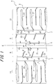
- FIG. 1 is a development view illustrating part of a tread portion 3 of a pneumatic tire (hereafter also referred to as a tire) 1 in one of the embodiments.
- a tire pneumatic tire
- two central land portion rows 9 and two outer land portion rows 11 located on the outer sides of the respective central land portion rows 9 in the tire width direction are defined by one central main groove 5 continuously extending linearly along the tire circumferential direction on a tire equatorial plane E and two outer main grooves 7 continuously extending linearly along the tire circumferential direction on both sides of the central main groove 5.
- the central main groove 5 and the outer main grooves 7 need not necessarily extend linearly along the tire circumferential direction, and may extend in a zigzag or curved shape.
- Each central land portion row 9 has at least one first narrow groove 21 that is open to the central main groove 5, and at least one second narrow groove 23 that is open to the outer main groove 7.
- a plurality of first narrow grooves 21 are arranged at regular intervals p1 in the tire circumferential direction
- a plurality of second narrow grooves 23 are arranged at regular intervals p2 in the tire circumferential direction, where p1 and p2 are equal.
- Each first narrow groove 21 and each second narrow groove 23 are staggered so as to differ in position from each other in the tire circumferential direction.
- the intervals between the narrow grooves in the tire circumferential direction need not necessarily be regular intervals, and may be any intervals.
- Each outer land portion row 11 has at least one third narrow groove 25 that is open to the outer main groove 7.
- a plurality of third narrow grooves 25 are arranged at regular intervals p3 in the tire circumferential direction as with the first narrow grooves 21 and the second narrow grooves 23, where p3 is equal to p1 or p2.
- the length a of the first narrow groove 21 in the tire width direction and the length b of the second narrow groove 23 in the tire width direction satisfy the relationship a ⁇ b
- the angle ⁇ of the first narrow groove 21 to the tire width direction, the angle ⁇ of the second narrow groove 23 to the tire width direction, and the angle ⁇ of the third narrow groove 25 to the tire width direction satisfy the relationship ⁇ ⁇ ⁇ ⁇ ⁇ , as illustrated.
- the third narrow groove 25 connects to an extension groove 27 extending outward in the tire width direction at an angle different from that of the third narrow groove 25 in this example, though this is not a limitation.
- the length c of the third narrow groove 25 in the tire width direction is the length, measured along the tire width direction, of the narrow groove having the angle ⁇ to the tire width direction.
- a narrow groove not open to the outer main groove 7 is formed between adjacent extension grooves 27, though such a narrow groove may be omitted as in an example illustrated in FIG. 2(c) .
- the tread pattern of the tire 1 is point-symmetric with respect to a point on the tire equatorial plane E located at the center of the central main groove 5 in this example.
- the tread pattern may be line-symmetric with respect to the tire equatorial plane, or either half of the line-symmetric shape may be displaced in the tire circumferential direction. Hence, better wet performance can be achieved by using the tire with appropriate rotation direction.
- the smaller angle of the first narrow groove 21 to the tire width direction increases the ground contact pressure (hereafter also referred to as edge pressure) of the land portion edge adjacent to the groove, and enhances the effect of removing any water film between the tread surface and the road surface around the narrow groove. Accordingly, a decrease in drainage performance is prevented even when the first narrow groove 21 is shorter in the tire width direction. Meanwhile, the second narrow groove 23 which is longer in the tire width direction delivers high drainage performance.
- each central land portion row 9 is a rib-shaped land portion continuous in the tire circumferential direction, which resists deformation and has high rigidity as compared with block-shaped land portions of a land portion row divided by, for example, narrow grooves extending in the tire width direction.
- the staggered arrangement of the first narrow groove 21 and the second narrow groove 23, in addition to the smaller length a of the first narrow groove 21 in the tire width direction and the smaller angle ⁇ of the first narrow groove 21 to the tire width direction increases the rigidity of the central land portion row 9 and further improves dry performance.
- each central land portion row 9 having high rigidity contributes to high steering stability and braking performance.
- the larger angle of the third narrow groove 25 to the tire width direction moderately lowers the rigidity of each outer land portion row 11, and increases the footprint area of the outer land portion row 11 during braking. This further improves braking performance.
- the length a of the first narrow groove 21 in the tire width direction, the length b of the second narrow groove 23 in the tire width direction, and the length c of the third narrow groove 25 in the tire width direction preferably satisfy a ⁇ c ⁇ b.
- the depth of the first narrow groove 21 is 50% to 100% of the depth of the central main groove, and the depth of each of the second narrow groove and the third narrow groove is 50% to 100% of the depth of the outer main groove.
- the depth of the first narrow groove 21 is less than 50% of the depth of the central main groove or the depth of the second narrow groove or third narrow groove is less than 50% of the outer main groove, sufficient wet performance may not be ensured due to insufficient drainage performance.
- the effect of improving dry performance may be insufficient due to a decrease in rigidity of the land portion.
- the length a of the first narrow groove 21 in the tire width direction is preferably 5% to 30% of the width of the central land portion row 9 in the tire width direction.
- the drainage performance of the first narrow groove 21 is appropriately ensured to ensure sufficient wet performance, and also a decrease in rigidity of the central land portion row 9 is prevented to improve dry performance more reliably.
- the length a of the first narrow groove 21 in the tire width direction is less than 5% of the width of the central land portion row 9 in the tire width direction, sufficient wet performance may not be ensured due to insufficient drainage performance.
- the length a of the first narrow groove 21 in the tire width direction is more than 30% of the width of the central land portion row 9 in the tire width direction, the effect of improving dry performance may be insufficient due to a decrease in rigidity of the central land portion row 9.
- the angle ⁇ of the first narrow groove 21 to the tire width direction is preferably 15° or less. With this structure, drainage performance is ensured to ensure sufficient wet performance. If the angle ⁇ is more than 15°, sufficient wet performance may not be ensured due to a decrease in water film removal effect caused by lower edge pressure.
- the length b of the second narrow groove 23 in the tire width direction is preferably 30% to 90% of the width of the central land portion row 9 in the tire width direction.
- the drainage performance of the second narrow groove 23 is appropriately ensured to ensure sufficient wet performance, and also a decrease in rigidity of the central land portion row 9 is prevented to improve dry performance more reliably.
- the length b of the second narrow groove 23 in the tire width direction is less than 30% of the width of the central land portion row 9 in the tire width direction, sufficient wet performance may not be ensured due to insufficient drainage performance.
- the length b of the second narrow groove 23 in the tire width direction is more than 90% of the width of the central land portion row 9 in the tire width direction, the effect of improving dry performance may be insufficient due to a decrease in rigidity of the central land portion row 9.
- the angle ⁇ of the second narrow groove 23 to the tire width direction is preferably 15° to 30°.
- the drainage performance of the second narrow groove 23 is appropriately ensured to ensure sufficient wet performance, and also a decrease in rigidity of the central land portion row 9 is prevented to improve dry performance more reliably. If the angle ⁇ is less than 15°, the effect of improving braking performance on a dry road surface may be insufficient. If the angle ⁇ is more than 30°, the effect of improving steering stability on a dry road surface may be insufficient due to a decrease in rigidity of the central land portion row 9.
- the length c of the third narrow groove 25 in the tire width direction is preferably 5% to 30% of the width of the outer land portion row 11 in the tire width direction.
- the drainage performance of the third narrow groove is appropriately ensured to ensure sufficient wet performance, and also a decrease in rigidity of the outer land portion row 11 is prevented to improve dry performance more reliably.
- the length c of the third narrow groove 25 in the tire width direction is less than 5% of the width of the outer land portion row 11 in the tire width direction, sufficient wet performance may not be ensured due to insufficient drainage performance.
- the length c of the third narrow groove 25 in the tire width direction is more than 30% of the width of the outer land portion row 11 in the tire width direction, the effect of improving dry performance may be insufficient due to a decrease in rigidity of the outer land portion row 11.
- the angle ⁇ of the third narrow groove 25 to the tire width direction is preferably 30° to 50°.
- the drainage performance of the third narrow groove is appropriately ensured to ensure sufficient wet performance, and also a decrease in rigidity of the outer land portion row 11 is prevented to improve dry performance more reliably.
- the angle ⁇ of the third narrow groove 25 to the tire width direction is less than 30°, the effect of improving braking performance on a dry road surface may be insufficient.
- the angle ⁇ is more than 50°, the effect of improving steering stability on a dry road surface may be insufficient due to a decrease in rigidity of the outer land portion row 11.
- the groove width of each of the first narrow groove 21, second narrow groove 23, and third narrow groove 25 is preferably 0.2 mm to 3.0 mm.
- the volume of each narrow groove is secured to enhance drainage performance and thus ensure sufficient wet performance, and also the volume of each land portion is appropriately secured to enhance its rigidity and thus improve dry performance.
- the groove width of each of the first narrow groove 21, second narrow groove 23, and third narrow groove 25 is less than 0.2 mm, sufficient wet performance may not be ensured due to insufficient drainage performance.
- the groove width of each of the first narrow groove 21, second narrow groove 23, and third narrow groove 25 is more than 3.0 mm, the effect of improving dry performance may be insufficient due to a decrease in rigidity of the land portion row.
- the directions in which the first narrow groove 21, the second narrow groove 23, and the third narrow groove 25 in the tread half on the same side of the central main groove 5 in the tire width direction are inclined with respect to the tire width direction, as seen from their openings 21a, 23a, and 25a to the central main groove 5 and the outer main groove 7, are preferably the same.
- water between the tread surface and the road surface absorbed by each narrow groove is drained into the central main groove 5 or the outer main groove 7 in the same direction. Such efficient water drainage ensures wet performance.
- Comparative Examples 1 to 4 and Examples 1 to 3 have a tire size of 195/65R15 91H.
- Comparative Example 1 has a tread pattern illustrated in FIG. 2(a) .
- Comparative Example 2 has a tread pattern illustrated in FIG. 2(b) .
- Comparative Examples 3 and 4 and Examples 1 to 3 have a tread pattern illustrated in FIG. 2(c) .
- the tires of Comparative Examples 1 to 4 and Examples 1 to 3 have the same structure except their tread patterns.
- two central land portion rows 109 and two outer land portion rows 111 are defined by a central main groove 105 and outer main grooves 107 continuously extending along the entire circumference of the tire. Narrow grooves and the like are not formed in the central land portion rows 109 and the outer land portion rows 111.
- two central land portion rows 209 and two outer land portion rows 211 are defined by a central main groove 205 and outer main grooves 207 continuously extending along the entire circumference of the tire.
- Each central land portion row 209 is separated into a plurality of block-shaped land portions arranged in the tire circumferential direction, by narrow grooves 221 crossing the central land portion row 209.
- Each outer land portion row 211 is separated into a plurality of block-shaped land portions arranged in the tire circumferential direction, by narrow grooves 225 crossing the outer land portion row 211.
- two central land portion rows 309 and two outer land portion rows 311 are defined by a central main groove 305 and outer main grooves 307 continuously extending along the entire circumference of the tire.
- First narrow grooves 321 and second narrow grooves 323 are staggered in the tire circumferential direction in each central land portion row 309, and third narrow grooves 325 are formed in each outer land portion row 311.
- a be the length of the first narrow groove 321 in the tire width direction
- b be the length of the second narrow groove 323 in the tire width direction
- c be the length of the third narrow groove 325 in the tire width direction
- ⁇ be the angle of the first narrow groove 321 to the tire width direction
- ⁇ be the angle of the second narrow groove 323 to the tire width direction
- ⁇ be the angle of the third narrow groove 325 to the tire width direction.
- Table 1 Each of the values of a, b, and c is represented by an absolute value (mm) and a proportion (%) to the width of the land portion row.
- the wet steering stability was evaluated for each of the vehicles equipped with the respective tires, by a professional test driver's comprehensive subjective evaluation on performance for straight running and performance for cornering when running a test course on a wet road surface in various running modes.
- the evaluation results are expressed as indices with the result of Comparative Example 1 being 3, where a larger value denotes better wet steering stability.
- the results are shown in Table 1.
- the dry steering stability was evaluated for each of the vehicles equipped with the respective tires, by a professional test driver's comprehensive subjective evaluation on performance for straight running and performance for cornering when running a test course on a dry road surface in various running modes.
- the evaluation results are expressed as indices with the result of Comparative Example 1 being 3, where a larger value denotes better dry steering stability.
- the results are shown in Table 1.
Landscapes
- Engineering & Computer Science (AREA)
- Mechanical Engineering (AREA)
- Tires In General (AREA)
Applications Claiming Priority (2)
| Application Number | Priority Date | Filing Date | Title |
|---|---|---|---|
| JP2013144435A JP5781566B2 (ja) | 2013-07-10 | 2013-07-10 | 空気入りタイヤ |
| PCT/JP2014/003553 WO2015004888A1 (ja) | 2013-07-10 | 2014-07-03 | 空気入りタイヤ |
Publications (3)
| Publication Number | Publication Date |
|---|---|
| EP3020575A1 true EP3020575A1 (de) | 2016-05-18 |
| EP3020575A4 EP3020575A4 (de) | 2016-07-13 |
| EP3020575B1 EP3020575B1 (de) | 2017-10-11 |
Family
ID=52279594
Family Applications (1)
| Application Number | Title | Priority Date | Filing Date |
|---|---|---|---|
| EP14823733.2A Active EP3020575B1 (de) | 2013-07-10 | 2014-07-03 | Luftreifen |
Country Status (5)
| Country | Link |
|---|---|
| US (1) | US10173475B2 (de) |
| EP (1) | EP3020575B1 (de) |
| JP (1) | JP5781566B2 (de) |
| CN (1) | CN105358341B (de) |
| WO (1) | WO2015004888A1 (de) |
Families Citing this family (8)
| Publication number | Priority date | Publication date | Assignee | Title |
|---|---|---|---|---|
| JP6445916B2 (ja) * | 2015-04-01 | 2018-12-26 | 株式会社ブリヂストン | タイヤ |
| JP6594051B2 (ja) * | 2015-06-08 | 2019-10-23 | 株式会社ブリヂストン | タイヤ |
| JP6632363B2 (ja) * | 2015-12-16 | 2020-01-22 | Toyo Tire株式会社 | 空気入りタイヤ |
| JP6710542B2 (ja) * | 2016-03-02 | 2020-06-17 | 株式会社ブリヂストン | 空気入りタイヤ |
| JP6816613B2 (ja) * | 2017-03-31 | 2021-01-20 | 住友ゴム工業株式会社 | タイヤ |
| JP6937216B2 (ja) | 2017-10-13 | 2021-09-22 | Toyo Tire株式会社 | 空気入りタイヤ |
| JP6929188B2 (ja) | 2017-10-13 | 2021-09-01 | Toyo Tire株式会社 | 空気入りタイヤ |
| JP6949654B2 (ja) | 2017-10-13 | 2021-10-13 | Toyo Tire株式会社 | 空気入りタイヤ |
Family Cites Families (14)
| Publication number | Priority date | Publication date | Assignee | Title |
|---|---|---|---|---|
| JP3061276B2 (ja) * | 1988-07-29 | 2000-07-10 | 住友ゴム工業株式会社 | 空気入りタイヤ |
| DK0473860T3 (da) * | 1990-09-05 | 1995-02-13 | Goodyear Tire & Rubber | Dækslidbane til store motorkøretøjer |
| JPH05178016A (ja) * | 1991-12-27 | 1993-07-20 | Yokohama Rubber Co Ltd:The | 重荷重用空気入りラジアルタイヤ |
| US5580404A (en) * | 1993-08-30 | 1996-12-03 | The Goodyear Tire & Rubber Company | Tread including tie bars and sipes |
| US6196288B1 (en) * | 1997-12-15 | 2001-03-06 | Michelin Recherche Et Technique S.A. | Siping geometry to delay the onset of rib edge wear in truck tires |
| JP4420623B2 (ja) * | 2003-05-28 | 2010-02-24 | 株式会社ブリヂストン | 空気入りタイヤ |
| US8267135B2 (en) * | 2004-09-24 | 2012-09-18 | Bridgestone Corporation | Pneumatic tire with tread having circumferential grooves and lug grooves |
| JP4330561B2 (ja) * | 2005-07-12 | 2009-09-16 | 住友ゴム工業株式会社 | 重荷重用タイヤ |
| JP4950491B2 (ja) * | 2005-12-29 | 2012-06-13 | 住友ゴム工業株式会社 | 重荷重用タイヤ |
| JP2009051453A (ja) | 2007-08-29 | 2009-03-12 | Yokohama Rubber Co Ltd:The | 空気入りタイヤ |
| JP5438609B2 (ja) * | 2010-07-07 | 2014-03-12 | 住友ゴム工業株式会社 | 空気入りタイヤ |
| CN103097149B (zh) * | 2010-08-25 | 2015-11-25 | 株式会社普利司通 | 充气轮胎 |
| JP2013078984A (ja) * | 2011-10-03 | 2013-05-02 | Sumitomo Rubber Ind Ltd | 空気入りタイヤ |
| JP5391262B2 (ja) * | 2011-12-29 | 2014-01-15 | 住友ゴム工業株式会社 | 空気入りタイヤ |
-
2013
- 2013-07-10 JP JP2013144435A patent/JP5781566B2/ja not_active Expired - Fee Related
-
2014
- 2014-07-03 WO PCT/JP2014/003553 patent/WO2015004888A1/ja active Application Filing
- 2014-07-03 EP EP14823733.2A patent/EP3020575B1/de active Active
- 2014-07-03 US US14/901,046 patent/US10173475B2/en active Active
- 2014-07-03 CN CN201480039117.9A patent/CN105358341B/zh active Active
Non-Patent Citations (3)
| Title |
|---|
| No further relevant documents disclosed * |
| None * |
| See also references of WO2015004888A1 * |
Also Published As
| Publication number | Publication date |
|---|---|
| EP3020575B1 (de) | 2017-10-11 |
| CN105358341A (zh) | 2016-02-24 |
| JP5781566B2 (ja) | 2015-09-24 |
| WO2015004888A1 (ja) | 2015-01-15 |
| US20160185158A1 (en) | 2016-06-30 |
| US10173475B2 (en) | 2019-01-08 |
| EP3020575A4 (de) | 2016-07-13 |
| CN105358341B (zh) | 2017-06-30 |
| JP2015016751A (ja) | 2015-01-29 |
Similar Documents
| Publication | Publication Date | Title |
|---|---|---|
| EP3020575B1 (de) | Luftreifen | |
| US9994077B2 (en) | Pneumatic tire | |
| US10328751B2 (en) | Pneumatic tire | |
| US9346323B2 (en) | Pneumatic tire | |
| US20170120688A1 (en) | Pneumatic Tire | |
| JP2010247759A (ja) | 空気入りタイヤ | |
| CN104981362B (zh) | 充气轮胎 | |
| EP2990230B1 (de) | Luftreifen | |
| CN106515316B (zh) | 充气轮胎 | |
| JP2009262675A (ja) | 空気入りタイヤ | |
| JP5952797B2 (ja) | 空気入りタイヤ | |
| WO2014126048A1 (ja) | 空気入りタイヤ | |
| JP6088336B2 (ja) | 空気入りタイヤ | |
| EP2689940B1 (de) | Luftreifen | |
| JP2014073776A (ja) | 空気入りタイヤ | |
| JP6631003B2 (ja) | 空気入りタイヤ | |
| JP6143341B2 (ja) | タイヤ | |
| CN106427402B (zh) | 充气轮胎 | |
| JP4929466B2 (ja) | 空気入りタイヤ | |
| JP2016088284A (ja) | 空気入りタイヤ | |
| EP2987655B1 (de) | Luftreifen | |
| JP5635145B2 (ja) | タイヤ | |
| JP5437851B2 (ja) | 空気入りタイヤ | |
| JP2016022807A (ja) | 空気入りタイヤ | |
| JP6612587B2 (ja) | 空気入りタイヤ |
Legal Events
| Date | Code | Title | Description |
|---|---|---|---|
| PUAI | Public reference made under article 153(3) epc to a published international application that has entered the european phase |
Free format text: ORIGINAL CODE: 0009012 |
|
| 17P | Request for examination filed |
Effective date: 20160108 |
|
| AK | Designated contracting states |
Kind code of ref document: A1 Designated state(s): AL AT BE BG CH CY CZ DE DK EE ES FI FR GB GR HR HU IE IS IT LI LT LU LV MC MK MT NL NO PL PT RO RS SE SI SK SM TR |
|
| AX | Request for extension of the european patent |
Extension state: BA ME |
|
| A4 | Supplementary search report drawn up and despatched |
Effective date: 20160615 |
|
| RIC1 | Information provided on ipc code assigned before grant |
Ipc: B60C 11/04 20060101AFI20160609BHEP Ipc: B60C 11/03 20060101ALI20160609BHEP Ipc: B60C 11/12 20060101ALI20160609BHEP |
|
| DAX | Request for extension of the european patent (deleted) | ||
| GRAP | Despatch of communication of intention to grant a patent |
Free format text: ORIGINAL CODE: EPIDOSNIGR1 |
|
| RIC1 | Information provided on ipc code assigned before grant |
Ipc: B60C 11/03 20060101ALI20170403BHEP Ipc: B60C 11/04 20060101AFI20170403BHEP Ipc: B60C 11/12 20060101ALI20170403BHEP |
|
| INTG | Intention to grant announced |
Effective date: 20170421 |
|
| GRAS | Grant fee paid |
Free format text: ORIGINAL CODE: EPIDOSNIGR3 |
|
| GRAA | (expected) grant |
Free format text: ORIGINAL CODE: 0009210 |
|
| AK | Designated contracting states |
Kind code of ref document: B1 Designated state(s): AL AT BE BG CH CY CZ DE DK EE ES FI FR GB GR HR HU IE IS IT LI LT LU LV MC MK MT NL NO PL PT RO RS SE SI SK SM TR |
|
| REG | Reference to a national code |
Ref country code: GB Ref legal event code: FG4D |
|
| REG | Reference to a national code |
Ref country code: CH Ref legal event code: EP |
|
| REG | Reference to a national code |
Ref country code: IE Ref legal event code: FG4D |
|
| REG | Reference to a national code |
Ref country code: AT Ref legal event code: REF Ref document number: 935673 Country of ref document: AT Kind code of ref document: T Effective date: 20171115 |
|
| REG | Reference to a national code |
Ref country code: DE Ref legal event code: R096 Ref document number: 602014015806 Country of ref document: DE |
|
| REG | Reference to a national code |
Ref country code: NL Ref legal event code: MP Effective date: 20171011 |
|
| REG | Reference to a national code |
Ref country code: LT Ref legal event code: MG4D |
|
| REG | Reference to a national code |
Ref country code: AT Ref legal event code: MK05 Ref document number: 935673 Country of ref document: AT Kind code of ref document: T Effective date: 20171011 |
|
| PG25 | Lapsed in a contracting state [announced via postgrant information from national office to epo] |
Ref country code: NL Free format text: LAPSE BECAUSE OF FAILURE TO SUBMIT A TRANSLATION OF THE DESCRIPTION OR TO PAY THE FEE WITHIN THE PRESCRIBED TIME-LIMIT Effective date: 20171011 |
|
| PG25 | Lapsed in a contracting state [announced via postgrant information from national office to epo] |
Ref country code: FI Free format text: LAPSE BECAUSE OF FAILURE TO SUBMIT A TRANSLATION OF THE DESCRIPTION OR TO PAY THE FEE WITHIN THE PRESCRIBED TIME-LIMIT Effective date: 20171011 Ref country code: LT Free format text: LAPSE BECAUSE OF FAILURE TO SUBMIT A TRANSLATION OF THE DESCRIPTION OR TO PAY THE FEE WITHIN THE PRESCRIBED TIME-LIMIT Effective date: 20171011 Ref country code: SE Free format text: LAPSE BECAUSE OF FAILURE TO SUBMIT A TRANSLATION OF THE DESCRIPTION OR TO PAY THE FEE WITHIN THE PRESCRIBED TIME-LIMIT Effective date: 20171011 Ref country code: ES Free format text: LAPSE BECAUSE OF FAILURE TO SUBMIT A TRANSLATION OF THE DESCRIPTION OR TO PAY THE FEE WITHIN THE PRESCRIBED TIME-LIMIT Effective date: 20171011 Ref country code: NO Free format text: LAPSE BECAUSE OF FAILURE TO SUBMIT A TRANSLATION OF THE DESCRIPTION OR TO PAY THE FEE WITHIN THE PRESCRIBED TIME-LIMIT Effective date: 20180111 |
|
| PG25 | Lapsed in a contracting state [announced via postgrant information from national office to epo] |
Ref country code: GR Free format text: LAPSE BECAUSE OF FAILURE TO SUBMIT A TRANSLATION OF THE DESCRIPTION OR TO PAY THE FEE WITHIN THE PRESCRIBED TIME-LIMIT Effective date: 20180112 Ref country code: IS Free format text: LAPSE BECAUSE OF FAILURE TO SUBMIT A TRANSLATION OF THE DESCRIPTION OR TO PAY THE FEE WITHIN THE PRESCRIBED TIME-LIMIT Effective date: 20180211 Ref country code: BG Free format text: LAPSE BECAUSE OF FAILURE TO SUBMIT A TRANSLATION OF THE DESCRIPTION OR TO PAY THE FEE WITHIN THE PRESCRIBED TIME-LIMIT Effective date: 20180111 Ref country code: HR Free format text: LAPSE BECAUSE OF FAILURE TO SUBMIT A TRANSLATION OF THE DESCRIPTION OR TO PAY THE FEE WITHIN THE PRESCRIBED TIME-LIMIT Effective date: 20171011 Ref country code: LV Free format text: LAPSE BECAUSE OF FAILURE TO SUBMIT A TRANSLATION OF THE DESCRIPTION OR TO PAY THE FEE WITHIN THE PRESCRIBED TIME-LIMIT Effective date: 20171011 Ref country code: RS Free format text: LAPSE BECAUSE OF FAILURE TO SUBMIT A TRANSLATION OF THE DESCRIPTION OR TO PAY THE FEE WITHIN THE PRESCRIBED TIME-LIMIT Effective date: 20171011 Ref country code: AT Free format text: LAPSE BECAUSE OF FAILURE TO SUBMIT A TRANSLATION OF THE DESCRIPTION OR TO PAY THE FEE WITHIN THE PRESCRIBED TIME-LIMIT Effective date: 20171011 |
|
| REG | Reference to a national code |
Ref country code: DE Ref legal event code: R097 Ref document number: 602014015806 Country of ref document: DE |
|
| REG | Reference to a national code |
Ref country code: FR Ref legal event code: PLFP Year of fee payment: 5 |
|
| PG25 | Lapsed in a contracting state [announced via postgrant information from national office to epo] |
Ref country code: DK Free format text: LAPSE BECAUSE OF FAILURE TO SUBMIT A TRANSLATION OF THE DESCRIPTION OR TO PAY THE FEE WITHIN THE PRESCRIBED TIME-LIMIT Effective date: 20171011 Ref country code: EE Free format text: LAPSE BECAUSE OF FAILURE TO SUBMIT A TRANSLATION OF THE DESCRIPTION OR TO PAY THE FEE WITHIN THE PRESCRIBED TIME-LIMIT Effective date: 20171011 Ref country code: SK Free format text: LAPSE BECAUSE OF FAILURE TO SUBMIT A TRANSLATION OF THE DESCRIPTION OR TO PAY THE FEE WITHIN THE PRESCRIBED TIME-LIMIT Effective date: 20171011 Ref country code: CZ Free format text: LAPSE BECAUSE OF FAILURE TO SUBMIT A TRANSLATION OF THE DESCRIPTION OR TO PAY THE FEE WITHIN THE PRESCRIBED TIME-LIMIT Effective date: 20171011 |
|
| PLBE | No opposition filed within time limit |
Free format text: ORIGINAL CODE: 0009261 |
|
| STAA | Information on the status of an ep patent application or granted ep patent |
Free format text: STATUS: NO OPPOSITION FILED WITHIN TIME LIMIT |
|
| PG25 | Lapsed in a contracting state [announced via postgrant information from national office to epo] |
Ref country code: IT Free format text: LAPSE BECAUSE OF FAILURE TO SUBMIT A TRANSLATION OF THE DESCRIPTION OR TO PAY THE FEE WITHIN THE PRESCRIBED TIME-LIMIT Effective date: 20171011 Ref country code: RO Free format text: LAPSE BECAUSE OF FAILURE TO SUBMIT A TRANSLATION OF THE DESCRIPTION OR TO PAY THE FEE WITHIN THE PRESCRIBED TIME-LIMIT Effective date: 20171011 Ref country code: SM Free format text: LAPSE BECAUSE OF FAILURE TO SUBMIT A TRANSLATION OF THE DESCRIPTION OR TO PAY THE FEE WITHIN THE PRESCRIBED TIME-LIMIT Effective date: 20171011 Ref country code: PL Free format text: LAPSE BECAUSE OF FAILURE TO SUBMIT A TRANSLATION OF THE DESCRIPTION OR TO PAY THE FEE WITHIN THE PRESCRIBED TIME-LIMIT Effective date: 20171011 |
|
| 26N | No opposition filed |
Effective date: 20180712 |
|
| PG25 | Lapsed in a contracting state [announced via postgrant information from national office to epo] |
Ref country code: SI Free format text: LAPSE BECAUSE OF FAILURE TO SUBMIT A TRANSLATION OF THE DESCRIPTION OR TO PAY THE FEE WITHIN THE PRESCRIBED TIME-LIMIT Effective date: 20171011 |
|
| REG | Reference to a national code |
Ref country code: CH Ref legal event code: PL |
|
| GBPC | Gb: european patent ceased through non-payment of renewal fee |
Effective date: 20180703 |
|
| PG25 | Lapsed in a contracting state [announced via postgrant information from national office to epo] |
Ref country code: MC Free format text: LAPSE BECAUSE OF FAILURE TO SUBMIT A TRANSLATION OF THE DESCRIPTION OR TO PAY THE FEE WITHIN THE PRESCRIBED TIME-LIMIT Effective date: 20171011 Ref country code: LU Free format text: LAPSE BECAUSE OF NON-PAYMENT OF DUE FEES Effective date: 20180703 |
|
| REG | Reference to a national code |
Ref country code: BE Ref legal event code: MM Effective date: 20180731 |
|
| REG | Reference to a national code |
Ref country code: IE Ref legal event code: MM4A |
|
| PG25 | Lapsed in a contracting state [announced via postgrant information from national office to epo] |
Ref country code: IE Free format text: LAPSE BECAUSE OF NON-PAYMENT OF DUE FEES Effective date: 20180703 Ref country code: CH Free format text: LAPSE BECAUSE OF NON-PAYMENT OF DUE FEES Effective date: 20180731 Ref country code: GB Free format text: LAPSE BECAUSE OF NON-PAYMENT OF DUE FEES Effective date: 20180703 Ref country code: LI Free format text: LAPSE BECAUSE OF NON-PAYMENT OF DUE FEES Effective date: 20180731 |
|
| PG25 | Lapsed in a contracting state [announced via postgrant information from national office to epo] |
Ref country code: BE Free format text: LAPSE BECAUSE OF NON-PAYMENT OF DUE FEES Effective date: 20180731 |
|
| PG25 | Lapsed in a contracting state [announced via postgrant information from national office to epo] |
Ref country code: MT Free format text: LAPSE BECAUSE OF NON-PAYMENT OF DUE FEES Effective date: 20180703 |
|
| PG25 | Lapsed in a contracting state [announced via postgrant information from national office to epo] |
Ref country code: TR Free format text: LAPSE BECAUSE OF FAILURE TO SUBMIT A TRANSLATION OF THE DESCRIPTION OR TO PAY THE FEE WITHIN THE PRESCRIBED TIME-LIMIT Effective date: 20171011 |
|
| PG25 | Lapsed in a contracting state [announced via postgrant information from national office to epo] |
Ref country code: PT Free format text: LAPSE BECAUSE OF FAILURE TO SUBMIT A TRANSLATION OF THE DESCRIPTION OR TO PAY THE FEE WITHIN THE PRESCRIBED TIME-LIMIT Effective date: 20171011 |
|
| PG25 | Lapsed in a contracting state [announced via postgrant information from national office to epo] |
Ref country code: MK Free format text: LAPSE BECAUSE OF NON-PAYMENT OF DUE FEES Effective date: 20171011 Ref country code: HU Free format text: LAPSE BECAUSE OF FAILURE TO SUBMIT A TRANSLATION OF THE DESCRIPTION OR TO PAY THE FEE WITHIN THE PRESCRIBED TIME-LIMIT; INVALID AB INITIO Effective date: 20140703 Ref country code: CY Free format text: LAPSE BECAUSE OF FAILURE TO SUBMIT A TRANSLATION OF THE DESCRIPTION OR TO PAY THE FEE WITHIN THE PRESCRIBED TIME-LIMIT Effective date: 20171011 |
|
| PG25 | Lapsed in a contracting state [announced via postgrant information from national office to epo] |
Ref country code: AL Free format text: LAPSE BECAUSE OF FAILURE TO SUBMIT A TRANSLATION OF THE DESCRIPTION OR TO PAY THE FEE WITHIN THE PRESCRIBED TIME-LIMIT Effective date: 20171011 |
|
| P01 | Opt-out of the competence of the unified patent court (upc) registered |
Effective date: 20230531 |
|
| PGFP | Annual fee paid to national office [announced via postgrant information from national office to epo] |
Ref country code: FR Payment date: 20230726 Year of fee payment: 10 Ref country code: DE Payment date: 20230719 Year of fee payment: 10 |