EP3015047A1 - Endoskopsystem - Google Patents
Endoskopsystem Download PDFInfo
- Publication number
- EP3015047A1 EP3015047A1 EP14817175.4A EP14817175A EP3015047A1 EP 3015047 A1 EP3015047 A1 EP 3015047A1 EP 14817175 A EP14817175 A EP 14817175A EP 3015047 A1 EP3015047 A1 EP 3015047A1
- Authority
- EP
- European Patent Office
- Prior art keywords
- electrode
- power
- unit
- channel
- reception
- Prior art date
- Legal status (The legal status is an assumption and is not a legal conclusion. Google has not performed a legal analysis and makes no representation as to the accuracy of the status listed.)
- Withdrawn
Links
- 230000005540 biological transmission Effects 0.000 claims abstract description 132
- 238000003780 insertion Methods 0.000 claims abstract description 45
- 230000037431 insertion Effects 0.000 claims abstract description 45
- 230000005684 electric field Effects 0.000 claims abstract description 19
- 239000011810 insulating material Substances 0.000 claims description 11
- 238000003384 imaging method Methods 0.000 claims description 8
- 239000003990 capacitor Substances 0.000 description 24
- 238000010586 diagram Methods 0.000 description 20
- 229910052751 metal Inorganic materials 0.000 description 14
- 239000002184 metal Substances 0.000 description 14
- 239000004020 conductor Substances 0.000 description 9
- 230000008878 coupling Effects 0.000 description 7
- 238000010168 coupling process Methods 0.000 description 7
- 238000005859 coupling reaction Methods 0.000 description 7
- 238000006243 chemical reaction Methods 0.000 description 6
- 230000000694 effects Effects 0.000 description 6
- RYGMFSIKBFXOCR-UHFFFAOYSA-N Copper Chemical compound [Cu] RYGMFSIKBFXOCR-UHFFFAOYSA-N 0.000 description 5
- 230000005672 electromagnetic field Effects 0.000 description 5
- 229920005989 resin Polymers 0.000 description 5
- 239000011347 resin Substances 0.000 description 5
- 229910052802 copper Inorganic materials 0.000 description 4
- 239000010949 copper Substances 0.000 description 4
- 230000008859 change Effects 0.000 description 3
- 238000009413 insulation Methods 0.000 description 3
- 239000007769 metal material Substances 0.000 description 3
- 229910001220 stainless steel Inorganic materials 0.000 description 3
- 239000010935 stainless steel Substances 0.000 description 3
- 230000015556 catabolic process Effects 0.000 description 2
- 230000003247 decreasing effect Effects 0.000 description 2
- NBVXSUQYWXRMNV-UHFFFAOYSA-N fluoromethane Chemical compound FC NBVXSUQYWXRMNV-UHFFFAOYSA-N 0.000 description 2
- 230000020169 heat generation Effects 0.000 description 2
- 230000007246 mechanism Effects 0.000 description 2
- 238000000034 method Methods 0.000 description 2
- 230000003071 parasitic effect Effects 0.000 description 2
- 238000007747 plating Methods 0.000 description 2
- 230000009467 reduction Effects 0.000 description 2
- 229910052709 silver Inorganic materials 0.000 description 2
- 239000004332 silver Substances 0.000 description 2
- BQCADISMDOOEFD-UHFFFAOYSA-N Silver Chemical compound [Ag] BQCADISMDOOEFD-UHFFFAOYSA-N 0.000 description 1
- 230000004075 alteration Effects 0.000 description 1
- 229910052782 aluminium Inorganic materials 0.000 description 1
- XAGFODPZIPBFFR-UHFFFAOYSA-N aluminium Chemical compound [Al] XAGFODPZIPBFFR-UHFFFAOYSA-N 0.000 description 1
- 210000000436 anus Anatomy 0.000 description 1
- 230000009286 beneficial effect Effects 0.000 description 1
- 230000008901 benefit Effects 0.000 description 1
- 238000001574 biopsy Methods 0.000 description 1
- 230000015572 biosynthetic process Effects 0.000 description 1
- 230000015271 coagulation Effects 0.000 description 1
- 238000005345 coagulation Methods 0.000 description 1
- 239000012141 concentrate Substances 0.000 description 1
- 239000011889 copper foil Substances 0.000 description 1
- 239000003822 epoxy resin Substances 0.000 description 1
- 238000001704 evaporation Methods 0.000 description 1
- PCHJSUWPFVWCPO-UHFFFAOYSA-N gold Chemical compound [Au] PCHJSUWPFVWCPO-UHFFFAOYSA-N 0.000 description 1
- 229910052737 gold Inorganic materials 0.000 description 1
- 239000010931 gold Substances 0.000 description 1
- 230000023597 hemostasis Effects 0.000 description 1
- 230000002439 hemostatic effect Effects 0.000 description 1
- 210000000214 mouth Anatomy 0.000 description 1
- 230000002093 peripheral effect Effects 0.000 description 1
- 229920000647 polyepoxide Polymers 0.000 description 1
- 229920005749 polyurethane resin Polymers 0.000 description 1
- 238000003825 pressing Methods 0.000 description 1
- 230000008569 process Effects 0.000 description 1
- 239000004065 semiconductor Substances 0.000 description 1
- 238000007493 shaping process Methods 0.000 description 1
- XLYOFNOQVPJJNP-UHFFFAOYSA-N water Substances O XLYOFNOQVPJJNP-UHFFFAOYSA-N 0.000 description 1
Images


Classifications
-
- A—HUMAN NECESSITIES
- A61—MEDICAL OR VETERINARY SCIENCE; HYGIENE
- A61B—DIAGNOSIS; SURGERY; IDENTIFICATION
- A61B1/00—Instruments for performing medical examinations of the interior of cavities or tubes of the body by visual or photographical inspection, e.g. endoscopes; Illuminating arrangements therefor
- A61B1/012—Instruments for performing medical examinations of the interior of cavities or tubes of the body by visual or photographical inspection, e.g. endoscopes; Illuminating arrangements therefor characterised by internal passages or accessories therefor
- A61B1/018—Instruments for performing medical examinations of the interior of cavities or tubes of the body by visual or photographical inspection, e.g. endoscopes; Illuminating arrangements therefor characterised by internal passages or accessories therefor for receiving instruments
-
- A—HUMAN NECESSITIES
- A61—MEDICAL OR VETERINARY SCIENCE; HYGIENE
- A61B—DIAGNOSIS; SURGERY; IDENTIFICATION
- A61B1/00—Instruments for performing medical examinations of the interior of cavities or tubes of the body by visual or photographical inspection, e.g. endoscopes; Illuminating arrangements therefor
- A61B1/00002—Operational features of endoscopes
- A61B1/00025—Operational features of endoscopes characterised by power management
- A61B1/00027—Operational features of endoscopes characterised by power management characterised by power supply
- A61B1/00029—Operational features of endoscopes characterised by power management characterised by power supply externally powered, e.g. wireless
-
- A—HUMAN NECESSITIES
- A61—MEDICAL OR VETERINARY SCIENCE; HYGIENE
- A61B—DIAGNOSIS; SURGERY; IDENTIFICATION
- A61B1/00—Instruments for performing medical examinations of the interior of cavities or tubes of the body by visual or photographical inspection, e.g. endoscopes; Illuminating arrangements therefor
- A61B1/00064—Constructional details of the endoscope body
- A61B1/00071—Insertion part of the endoscope body
- A61B1/0008—Insertion part of the endoscope body characterised by distal tip features
- A61B1/00087—Tools
-
- A—HUMAN NECESSITIES
- A61—MEDICAL OR VETERINARY SCIENCE; HYGIENE
- A61B—DIAGNOSIS; SURGERY; IDENTIFICATION
- A61B18/00—Surgical instruments, devices or methods for transferring non-mechanical forms of energy to or from the body
- A61B18/04—Surgical instruments, devices or methods for transferring non-mechanical forms of energy to or from the body by heating
- A61B18/12—Surgical instruments, devices or methods for transferring non-mechanical forms of energy to or from the body by heating by passing a current through the tissue to be heated, e.g. high-frequency current
- A61B18/14—Probes or electrodes therefor
- A61B18/1442—Probes having pivoting end effectors, e.g. forceps
-
- A—HUMAN NECESSITIES
- A61—MEDICAL OR VETERINARY SCIENCE; HYGIENE
- A61B—DIAGNOSIS; SURGERY; IDENTIFICATION
- A61B18/00—Surgical instruments, devices or methods for transferring non-mechanical forms of energy to or from the body
- A61B18/04—Surgical instruments, devices or methods for transferring non-mechanical forms of energy to or from the body by heating
- A61B18/12—Surgical instruments, devices or methods for transferring non-mechanical forms of energy to or from the body by heating by passing a current through the tissue to be heated, e.g. high-frequency current
- A61B18/14—Probes or electrodes therefor
- A61B18/1492—Probes or electrodes therefor having a flexible, catheter-like structure, e.g. for heart ablation
-
- H—ELECTRICITY
- H02—GENERATION; CONVERSION OR DISTRIBUTION OF ELECTRIC POWER
- H02J—CIRCUIT ARRANGEMENTS OR SYSTEMS FOR SUPPLYING OR DISTRIBUTING ELECTRIC POWER; SYSTEMS FOR STORING ELECTRIC ENERGY
- H02J50/00—Circuit arrangements or systems for wireless supply or distribution of electric power
- H02J50/05—Circuit arrangements or systems for wireless supply or distribution of electric power using capacitive coupling
-
- A—HUMAN NECESSITIES
- A61—MEDICAL OR VETERINARY SCIENCE; HYGIENE
- A61B—DIAGNOSIS; SURGERY; IDENTIFICATION
- A61B1/00—Instruments for performing medical examinations of the interior of cavities or tubes of the body by visual or photographical inspection, e.g. endoscopes; Illuminating arrangements therefor
- A61B1/00112—Connection or coupling means
- A61B1/00121—Connectors, fasteners and adapters, e.g. on the endoscope handle
- A61B1/00124—Connectors, fasteners and adapters, e.g. on the endoscope handle electrical, e.g. electrical plug-and-socket connection
-
- A—HUMAN NECESSITIES
- A61—MEDICAL OR VETERINARY SCIENCE; HYGIENE
- A61B—DIAGNOSIS; SURGERY; IDENTIFICATION
- A61B18/00—Surgical instruments, devices or methods for transferring non-mechanical forms of energy to or from the body
- A61B18/04—Surgical instruments, devices or methods for transferring non-mechanical forms of energy to or from the body by heating
- A61B18/12—Surgical instruments, devices or methods for transferring non-mechanical forms of energy to or from the body by heating by passing a current through the tissue to be heated, e.g. high-frequency current
- A61B18/14—Probes or electrodes therefor
- A61B18/16—Indifferent or passive electrodes for grounding
-
- A—HUMAN NECESSITIES
- A61—MEDICAL OR VETERINARY SCIENCE; HYGIENE
- A61B—DIAGNOSIS; SURGERY; IDENTIFICATION
- A61B17/00—Surgical instruments, devices or methods, e.g. tourniquets
- A61B17/00234—Surgical instruments, devices or methods, e.g. tourniquets for minimally invasive surgery
- A61B2017/00292—Surgical instruments, devices or methods, e.g. tourniquets for minimally invasive surgery mounted on or guided by flexible, e.g. catheter-like, means
- A61B2017/00296—Surgical instruments, devices or methods, e.g. tourniquets for minimally invasive surgery mounted on or guided by flexible, e.g. catheter-like, means mounted on an endoscope
-
- A—HUMAN NECESSITIES
- A61—MEDICAL OR VETERINARY SCIENCE; HYGIENE
- A61B—DIAGNOSIS; SURGERY; IDENTIFICATION
- A61B17/00—Surgical instruments, devices or methods, e.g. tourniquets
- A61B17/00234—Surgical instruments, devices or methods, e.g. tourniquets for minimally invasive surgery
- A61B2017/00292—Surgical instruments, devices or methods, e.g. tourniquets for minimally invasive surgery mounted on or guided by flexible, e.g. catheter-like, means
- A61B2017/0034—Surgical instruments, devices or methods, e.g. tourniquets for minimally invasive surgery mounted on or guided by flexible, e.g. catheter-like, means adapted to be inserted through a working channel of an endoscope
-
- A—HUMAN NECESSITIES
- A61—MEDICAL OR VETERINARY SCIENCE; HYGIENE
- A61B—DIAGNOSIS; SURGERY; IDENTIFICATION
- A61B18/00—Surgical instruments, devices or methods for transferring non-mechanical forms of energy to or from the body
- A61B2018/00053—Mechanical features of the instrument of device
- A61B2018/00172—Connectors and adapters therefor
- A61B2018/00178—Electrical connectors
-
- A—HUMAN NECESSITIES
- A61—MEDICAL OR VETERINARY SCIENCE; HYGIENE
- A61B—DIAGNOSIS; SURGERY; IDENTIFICATION
- A61B18/00—Surgical instruments, devices or methods for transferring non-mechanical forms of energy to or from the body
- A61B2018/00982—Surgical instruments, devices or methods for transferring non-mechanical forms of energy to or from the body combined with or comprising means for visual or photographic inspections inside the body, e.g. endoscopes
-
- A—HUMAN NECESSITIES
- A61—MEDICAL OR VETERINARY SCIENCE; HYGIENE
- A61B—DIAGNOSIS; SURGERY; IDENTIFICATION
- A61B18/00—Surgical instruments, devices or methods for transferring non-mechanical forms of energy to or from the body
- A61B18/04—Surgical instruments, devices or methods for transferring non-mechanical forms of energy to or from the body by heating
- A61B18/12—Surgical instruments, devices or methods for transferring non-mechanical forms of energy to or from the body by heating by passing a current through the tissue to be heated, e.g. high-frequency current
- A61B18/1206—Generators therefor
- A61B2018/1286—Generators therefor having a specific transformer
-
- A—HUMAN NECESSITIES
- A61—MEDICAL OR VETERINARY SCIENCE; HYGIENE
- A61B—DIAGNOSIS; SURGERY; IDENTIFICATION
- A61B18/00—Surgical instruments, devices or methods for transferring non-mechanical forms of energy to or from the body
- A61B18/04—Surgical instruments, devices or methods for transferring non-mechanical forms of energy to or from the body by heating
- A61B18/12—Surgical instruments, devices or methods for transferring non-mechanical forms of energy to or from the body by heating by passing a current through the tissue to be heated, e.g. high-frequency current
- A61B18/14—Probes or electrodes therefor
- A61B2018/1405—Electrodes having a specific shape
- A61B2018/1412—Blade
-
- A—HUMAN NECESSITIES
- A61—MEDICAL OR VETERINARY SCIENCE; HYGIENE
- A61B—DIAGNOSIS; SURGERY; IDENTIFICATION
- A61B2560/00—Constructional details of operational features of apparatus; Accessories for medical measuring apparatus
- A61B2560/02—Operational features
- A61B2560/0204—Operational features of power management
- A61B2560/0214—Operational features of power management of power generation or supply
-
- H—ELECTRICITY
- H02—GENERATION; CONVERSION OR DISTRIBUTION OF ELECTRIC POWER
- H02J—CIRCUIT ARRANGEMENTS OR SYSTEMS FOR SUPPLYING OR DISTRIBUTING ELECTRIC POWER; SYSTEMS FOR STORING ELECTRIC ENERGY
- H02J2310/00—The network for supplying or distributing electric power characterised by its spatial reach or by the load
- H02J2310/10—The network having a local or delimited stationary reach
- H02J2310/20—The network being internal to a load
- H02J2310/23—The load being a medical device, a medical implant, or a life supporting device
Definitions
- the present invention relates to an endoscope system for wirelessly feeding power to a device passing through a channel of a flexible endoscope.
- US Patent No. 7,824,407 discloses high-frequency incision forceps for applying high-frequency current to a body tissue to do a treatment as a device passing through a channel of a flexible endoscope and inserted into a body.
- a cable is connected to devices such as the high-frequency incision forceps to supply power necessary for operation.
- this cable may disturb operator's operations and hence reduce operability.
- US Patent No. 6,187,002 and US Patent No. 6,206,875 disclose that power is wirelessly fed from a transmission electrode of a trocar to a reception electrode of a capacitive cordless electrosurgical instrument inserted in the trocar through capacitive coupling.
- the endoscope system in one aspect of the present invention is an endoscope system including: a flexible endoscope having a flexible insertion section including a distal end portion in which an imaging unit is arranged, an operation section arranged on a base end side of the insertion section, and a flexible channel that passes through the insertion section; a treatment tool with a treatment unit that comes into contact with a treated area of an object to be treated, the treatment unit being inserted from an insertion opening of the operation section, passing through the channel, and projecting from an opening of the distal end portion; a return electrode whose contact surface with the object to be treated is covered with an insulating material; and a power supply for outputting high-frequency power supplied to the treated area through the treatment unit and the return electrode, wherein the endoscope has a power transmission unit including a transmission electrode laid along a cylindrical outer circumferential surface of the channel to generate an alternating electric field to be applied to the channel by the high-frequency power input from the power supply, and the treatment tool has a power reception unit for receiving
- the endoscope system of another embodiment is an endoscope system including: a flexible endoscope having a flexible insertion section including a distal end portion in which an imaging unit is arranged, an operation section arranged on a base end side of the insertion section, and a flexible channel that passes through the insertion section; a treatment tool with a treatment unit that comes into contact with a treated area of an object to be treated, the treatment unit being inserted from an insertion opening of the operation section, passing through the channel, and projecting from an opening of the distal end portion; a return electrode that comes into contact with the object to be treated; and a power supply for outputting high-frequency power supplied to the treated area through the treatment unit and the return electrode, wherein the endoscope has a power transmission unit including a transmission electrode for generating an alternating electric field to be applied to the channel by the high-frequency power input from the power supply, and the treatment tool has a power reception unit including a reception electrode capacitively coupled to the transmission electrode to output received power to the treatment unit.
- an endoscope system including a highly operable device inserted into a channel of a flexible endoscope.
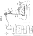
- an endoscope system 1 of the embodiment includes a flexible endoscope (hereinafter called "endoscope") 10, a treatment tool 20 as a device passing through a channel 14 of the endoscope 10, a power supply 30, and a return electrode 40.
- endoscope flexible endoscope
- the endoscope 10 has an insertion section 11 and an operation section 12 arranged on a base end side of the insertion section 11, and a universal cord 13 provided to extend from the operation section 12.
- the insertion section 11 includes a distal end portion 11A in which an imaging unit 15 (see FIG. 2 ) is arranged, a curved portion 11B for changing the direction of the distal end portion 11A, and a flexible, elongated soft portion 11C.
- the operation section 12 is a non-flexible section grasped by an operator to perform a directional operation of the distal end portion 11A, an air supply/water supply operation, an endoscopic image taking operation, and the like.
- the insertion section 11 is a flexible section to be inserted from the oral cavity or the anus of a patient as an object 2 to be treated into an alimentary tract.
- a processor 32 connected to the universal cord 13 of the endoscope 10 includes a control unit (not illustrated) composed of a CPU and the like for controlling the entire endoscope system 1 to process an imaging signal output from the imaging unit 15 and display an endoscopic image on a monitor 33.
- the power supply 30 connected to the processor 32 supplies high-frequency power to the treatment tool 20.
- a foot switch SW 31 controls ON/OFF of the output of the power supply 30.
- a line branched from the universal cord 13 may be connected directly to the power supply 30.
- the return electrode 40 made of a metal conductor such as stainless steel is a human body-side electrode.
- the return electrode 40 is applied to an object (patient) 2 to be treated, for example, to come into contact with a wide area of the back side so as to form a so-called return circuit.
- the endoscope 10 has a flexible channel 14 made of a resin tube passing through the insertion section 11 from an insertion opening 14A of the operation section 12 to an opening 14B of the distal end portion 11A.
- the treatment tool 20 is a monopolar high-frequency electrosurgical knife having a distal end portion 21A in which a treatment unit (knife electrode) 22 is arranged, an elongated, flexible insertion section 21B, and an operation section 21C arranged on the base end side of the insertion section 21B and operated by the operator outside the body.
- the treatment tool 20 is inserted from the insertion opening 14A to pass through the channel 14 and project the distal end portion 21A from the opening 14B.
- the power supply 30 outputs high-frequency power, for example, with a frequency of not less than 100 kHz and not more than 100 MHz.
- the frequency of the high-frequency power is preferably selected from frequencies allowed by the laws and the like, which is 13.56 MHz, for example. It is preferred, but not particularly limited to, that the waveform amplitude of the high-frequency power be of a sinusoidal wave because a general-purpose power supply can be used.
- the treatment tool 20 and the power supply 30 are not connected by wire. However, when the treatment tool 20 is inserted into the channel 14, the treatment tool 20 receives, in wireless power transmission, power required to do a treatment from the power supply 30 through the endoscope 10. Note that the wireless power transmission is the same in meaning as wireless power supply.
- the endoscope 10 has a power transmission unit 19 including a transmission electrode 18 to convert the high-frequency power output from the power supply 30 into an alternating electric field.
- the transmission electrode 18 of the endoscope 10 is made of a cylindrical conductor laid to cover the outer circumference of the channel 14.
- the channel 14 includes a flexible tube and a branch tube, and one side of the branch tube is connected to an air sending and sucking tube 14C.
- the power transmission unit 19 may be structured to have a hollow section with which part of the channel 14 is replaced as long as it is located inside of at least either of the operation section 12 and the insertion section 11.
- a component that forms the hollow section in the above structure is also regarded as part of the channel 14.
- the conductor of the transmission electrode 18 may be exposed to the inner surface of the hollow section in terms of the function as an electrode, it is preferred that the inner surface of the hollow section be sealed by an insulating material because the channel 14 is also used for sending and sucking air, and the like.
- the treatment tool 20 has a power reception unit 29 including a reception electrode 28 to receive an alternating electric field.
- the reception electrode 28 of the treatment tool 20 is made up of a cylindrical conductor laid along the outer circumferential surface of the insertion section 21B.
- a region of part of the insertion section 21B, where the reception electrode 28 is arranged, is so arranged that the conductor will not be exposed to the outermost circumferential surface, and if it can be inserted into the channel 14, the outer diameter ⁇ (20) of the region may be made larger than other regions.
- the reception electrode 28 of the treatment tool 20 cannot efficiently receive an alternating electric field generated by the transmission electrode 18 of the endoscope 10 until the treatment unit 22 projects from the opening 14B.
- the reception electrode 28 is in a state of being inserted in the transmission electrode 18. Therefore, in the endoscope system 1, the reception electrode 28 and the transmission electrode 18 are strongly capacitively coupled to each other in the state where the treatment unit 22 is projecting from the opening 14B so that the alternating electric field generated by the transmission electrode 18 can be received efficiently.
- the transmission electrode 18 laid along the outer surface of the cylindrical channel, and the reception electrode 28 laid along the outer surface of the cylindrical treatment tool are both cylindrical.
- the transmission electrode 18 and the reception electrode 28 arranged opposite to each other in a concentric fashion form a first capacitor C1.
- the treatment tool 20 has no physical contact (connection) with the endoscope 10 through the conductor.
- the power reception unit 29 of the treatment tool 20 is capacitively coupled to the power transmission unit 19 of the endoscope 10.
- FIG. 7 is a circuit diagram of the endoscope system 1.
- the high-frequency power output from the power supply 30 is output to the treatment unit 22 through the capacitor C1 formed by the power transmission unit 19 of the endoscope 10 and the power reception unit 29 of the treatment tool 20.
- the high-frequency power is supplied between the treatment unit 22 and the return electrode 40.
- wiring for connection between the power supply 30 and the return electrode 40 may be at a ground potential.
- the power of the return circuit flowing from the object 2 to be treated to the return electrode 40 flows through a large-area path. In other words, resistance R2 of the object 2 to be treated is low.
- resistance R2A of the treated area 2A is high and the density is high. Therefore, the applied power has little influence on the object 2 to be treated, while the Joule heat is generated in the treated area 2A being in contact with the treatment unit 22 so that the treated area 2A will be subjected to a treatment (exsection/hemostasis).
- the efficiency of wireless transmission through capacitive coupling is proportional to the magnitude of capacitive coupling between the transmission electrode 18 and the reception electrode 28, i.e. capacitance CA of the capacitor C1 formed by the transmission electrode 18 and the reception electrode 28.
- the capacitance C of the capacitor is proportional to a dielectric constant ⁇ between electrodes and a counter electrode area A, and inversely proportional to an inter-electrode distance g.
- the inner diameter ⁇ (14) of the channel 14 is larger than the outer diameter ⁇ (20) of the insertion section 21B so that the insertion section 21B of the treatment tool 20 can be inserted.
- ⁇ (14) 2.8 mm
- ⁇ (20) 2.6 mm.
- the thickness of the channel 14 is regarded as zero, when the electrodes of the capacitors C1 are coaxial with each other and not eccentric, the inter-electrode distance g therebetween is very short as 0.1 mm.
- the counter electrode area A is proportional to a length L of a shorter electrode.
- the length of the transmission electrode 18 and the reception electrode 28 be 1 cm or more. If the length is in the above range or more, power can be transmitted and received.
- the maximum length of the transmission electrode 18 and the reception electrode 28 is determined by a length D of the channel 14.
- the channel length D of the flexible endoscope 10 is about not less than 100 cm and not more than 230 cm, such as 200 cm.
- the maximum length of the transmission electrode 18 is about D
- the maximum length of the reception electrode 28 is also about D. Note that it is particularly preferred that the length of the transmission electrode 18 and the reception electrode 28 be not less than 5 cm and not more than 200 cm in terms of the transmission/reception efficiency and the self-inductance.
- an insulating material having a high dielectric constant ⁇ such as fluorocarbon resin, may be arranged between the transmission electrode 18 and the reception electrode 28 to increase the capacitance C.
- the capacitance C may be increased by a mechanism for making the center positions of the transmission electrode 18 and the reception electrode 28 eccentric to each other, or a mechanism for pressing the channel with the transmission electrode 18 laid to deform to the center side or to one side in order to reduce the inter-electrode distance g locally.
- a state in which the capacitance becomes the highest with the electrodes made not eccentric is a state in which the reception electrode 28 is inserted into the entire length of the transmission electrode 18. Therefore, it is preferred that the length of the reception electrode 28 be longer than the length of the transmission electrode 18, and in light of the projection amount d from the opening 14B of the treatment tool 20, it is particularly preferred that the total length of the reception electrodes 28 be (length of the transmission electrode 18 + projection amount d). Note that the projection amount d is, for example, not less than 1 cm and not more than 10 cm, though it depends on the treatment tool.
- the minimum length of these electrodes is a length at which parasitic capacitance in the circuit and capacitance involved in transmitting/receiving power, i.e. the capacitance CA of the capacitor C1 becomes substantially the same as each other.
- the parasitic capacitance in the circuit is higher than the capacitance involved in transmitting/receiving power, most of the supplied power does not reach the treatment unit.
- the treatment unit consumes more of the power input from the power transmission unit to the power reception unit, transmission efficiency becomes higher. Therefore, it is preferred that the load on the treatment unit, i.e., the resistance should be large compared with various resistive components in the circuit.
- the transmission electrode 18 is arranged in the operation section 12 of the channel 14 in FIG. 2 , it may be arranged in the soft portion 11C of the channel 14, or arranged in the operation section 12 and the soft portion 11C of the channel 14. Further, the first transmission electrode 18A may be arranged in the operation section 12 of the channel 14 and the second transmission electrode 18B may be arranged in the soft portion 11C of the channel 14. Further, although the length of the reception electrode 28 illustrated in FIG. 3 is short, it may be, for example, an electrode having almost the same length as the length of the insertion section 21B.
- the transmission electrode 18 and the reception electrode 28 are only need to be arranged in positions where the electrodes are strongly capacitively coupled to each other when the treatment unit 22 is in operation. Note that the transmission electrode 18 and the reception electrode 28 placed inside the flexible, soft portion 11C need to be flexible.
- the channel 14 is so used that a capacitor C1 short in inter-electrode distance g, wide in counter electrode area A, and high in capacitance CA can be formed.
- the endoscope system 1 including the flexible endoscope 10 having the flexible, elongated insertion section 11 (channel 14) is high in the efficiency of wireless power transmission because it can increase the length of the transmission electrode 18 and the reception electrode 28 according to the length of the insertion section 11.
- the capacitor C1 is made up of concentric counter electrodes, even when the treatment tool 20 rotates in the channel 14 around the longitudinal direction as its axis, the transmission electrode 18 and the reception electrode 28 are capacitively coupled stably. Thus, the operator can carry out an insertion operation without being conscious of the rotation of the treatment tool 20.
- the transmission electrode 18 is made of cylindrical metal laid to cover the outer circumference of the channel 14.
- a metal film made of copper or the like is formed on the outer circumferential surface of the channel 14 as a flexible tube by an evaporation method or a plating method to enable the formation of the transmission electrode 18.
- the reception electrode 28 can also be made by forming a metal film on the outer circumferential surface of the insertion section 21B of the treatment tool 20 in the same manner as the transmission electrode 18. Note that it is preferred that the surfaces of the transmission electrode 18 and the reception electrode 28 should be covered with insulating films to ensure the insulating performance and reliability.
- the transmission electrode 18 and the reception electrode 28 made of the metal films are easy to be laid on curved surfaces, and have flexibility.
- the same treatment tool 20 can be used even for multiple endoscopes different in channel length D.
- the arrangement position of the transmission electrode 18 should be set with reference to the opening 14B.
- the transmission electrode 18 of the endoscope only needs to be arranged in a position a predetermined distance D1 from the opening 14B.
- distance D2 from the insertion opening 14A to the transmission electrode 18 in an endoscope having a longer channel length D becomes longer than that of an endoscope having a shorter channel length D.
- the multiple endoscopes can wirelessly feed power to the treatment tool 20 efficiently.
- an endoscope system including one endoscope and multiple treatment tools has the same effect, where the power reception unit 29 is arranged in a position capable of receiving the alternating electric field generated by the power transmission unit 19 most efficiently in a state of inserting each of the treatment tools into the channel 14 up to the operating position, respectively.
- an endoscope side circuit including a power supply 30 and a power transmission unit 19 has no physical contact through a conductor with a treatment tool side circuit including a power reception unit 29 and a treatment unit 22 to apply current to a body tissue LT as a load section that consumes power.
- the power reception unit 29 is capacitively coupled to a non-radiative alternating electric field generated in a space near the power transmission unit 19.
- the power is supplied to the treatment unit 22 of the treatment tool 20 through the power reception unit 29 capacitively coupled.
- the treatment tool 20 in the endoscope system 1 has no wiring (cable) connected to the power supply 30, it is easy to handle the treatment tool 20 with good operability. Further, since the power transmission unit 19 is arranged inside the endoscope 10, a generated electromagnetic field is less likely to leak outside the endoscope 10, and the influence of the leakage electromagnetic field on peripheral devices is small. Further, since distance between a living body as an object to be treated and the power transmitting/receiving units is ensured, the influence of heat generation is small.
- the cylindrical reception electrode 28 is coaxial with the cylindrical transmission electrode 18 and the counter electrode area is largest among same-sized counter electrodes, the capacitance C of the capacitor is high.
- the reception electrode 28 and the transmission electrode 18 can be arranged over the entire length of the insertion section 11 of the flexible endoscope 10, it is easy to further increase the capacitance.
- a relative positional relationship between the power transmission unit 19 and the power reception unit 29 is defined by arranging the power transmission unit 19 inside the endoscope 10, the state of strongly capacitive coupling between the power transmission unit 19 and the power reception unit 29, i.e., a state of high power transmission efficiency can be maintained stably, and energy saving performance is excellent as well.
- the switch 31 is used to control ON/OFF of the power output to the treatment tool 20 as already described above.
- the switch is illustrated as the foot switch 31 in FIG. 1 , but the switch may be arranged in the power supply 30, the operation section 12 of the endoscope 10, or the operation section 21C of the treatment tool 20.
- the switch connected to the power supply 30 or the switch arranged in the power supply 30 controls ON/OFF of the output of the power supply 30.
- the switch arranged in the operation section 12 or the operation section 21C controls ON/OFF of power through an internal circuit of the power transmission unit 19 or the power reception unit 29.
- a Q value of the power transmission/reception circuit can be increased/decreased to make a vast change in transmission/reception efficiency in order to obtain the same effect as the ON/OFF control.
- the control of decreasing the Q value may cause a problem such as heat generation.
- the switch may be a button switch, a touch gesture-capable operating part, a speech-recognition operating part, or the like.
- the switch as power transmission starting/stopping means for starting or stopping output from the power supply 30 is arranged separately from the power supply 30, or arranged in the operation section 12 of the endoscope 10 or in the treatment tool 20.
- endoscope systems 1A to 1G, and the like as variations 1 to 6 of the first embodiment will be described. Since the endoscope systems 1A to 1G, and the like include the same components as the endoscope system 1 already described and are similar to the endoscope system 1, the same reference numerals are given to components having the same functions to omit the description thereof.
- All the endoscope systems 1A to 1G, and the like have the effects of the endoscope system 1, and further have more beneficial effects than the endoscope system 1, respectively.
- the endoscope system 1A has an inductance element 17 in a power transmission/reception circuit including the power transmission unit 19 of the endoscope 10 and the power reception unit 29 of the treatment tool 20.
- the addition of an inductance component causes the power transmission/reception circuit to form a serial resonance circuit with a predetermined resonant frequency F1.
- circuit capacitance Ctotal including the capacitance CA of the capacitor C1, circuit inductance Ltotal including the inductance element 17, and a frequency F0 of high-frequency power output from the power supply 30 have the following relation (Equation 1).
- the frequency F0 of the high-frequency power output from the power supply 30 coincides with the resonant frequency F1 of the power transmission/reception circuit. Therefore, the high-frequency power output from the power supply 30 is efficiently output to the treatment unit 22.
- the power reception unit 29 of the treatment tool 20 may include an inductance element, or the power transmission unit 19 and the power reception unit 29 may include inductance elements, respectively. Further, when the power transmission/reception circuit is a resonance circuit having the resonant frequency F1 as a whole, the inductance element may be arranged in the processor 32.
- voltage across the terminals of the inductance element in the resonance circuit is the same as the voltage across the terminals of the capacitor, and the inductance of the inductance element is set to compensate for a reactance using the capacitance of the capacitor and a specific frequency.
- the voltage across the terminals is inversely proportional to the capacitance. Therefore, the higher the capacitance of the capacitor, the lower the voltage across the terminals, and this can lead to reducing risk of insulation breakdown.
- the capacitance is too high, self-resonance may occur due to the self-inductance of the resonance circuit even without any inductance element 17, and this can deteriorate controllability.
- the capacitance needs to be low to arrange an inductance element in order to improve controllability.
- the capacitance is set in consideration of trade-off between the risk of insulation breakdown and controllability. Since the voltage across the terminals of the inductance element is proportional to the inductance, though not described in detail, the inductance element acts in an opposite way to the capacitance element.
- an endoscope system 1B has a variable inductance element 17B. Then, a control unit 32A adjusts the inductance of the variable inductance element 17B to make the resonant frequency F1 of the resonance circuit coincide with the frequency F0 of high-frequency power output from the power supply 30.
- the control unit 32A is, for example, arranged in the processor 32, the power supply 30, or the endoscope 10.
- the resonant frequency F1 of the resonance circuit varies because the capacitance of the capacitor C1 varies.
- the resonant frequency F1 is adjusted to coincide with the frequency F0 of high-frequency power.
- control unit 32A may control the power supply 30 according to the change in the resonant frequency F1 of the power transmission/reception circuit to change the frequency F0 of high-frequency power or an output value of the high-frequency power.
- the inductance element 17, 17B is described as part of the power transmission unit 19, but the inductance element 17, 17B and the control unit 32A may be, for example, part of the processor 32. Further, the inductance element 17 and the like may be arranged in the operation section 21C of the treatment tool 20. In other words, the inductance element 17, 17B and the control unit 32A have only to be included in any of the components in the endoscope system 1A, 1B.
- an impedance matching circuit may be arranged before the power transmission unit to make the impedance on the treatment unit side of the power transmission unit coincide with the output impedance of the power supply in order to suppress reflection so that the efficiency of power input from the power supply 30 to the resonance circuit will be increased.
- the impedance matching circuit composed of a combination of two or more elements such as a capacitance element and an inductance element may be part of the processor 32, or may be arranged in the operation section 21C of the treatment tool 20.
- the distribution of a generated alternating electric field, a capacitive coupling state, and the like greatly vary depending on the structure and arrangement of the transmission electrode 18 and the reception electrode 28.
- power can be wirelessly transmitted as long as the structure is such that an alternating electric field generated in the power transmission unit 19 causes capacitive coupling to the power reception unit 29.
- FIG. 10A to FIG. 13 illustrate electrodes as variations of the transmission electrode 18 and the reception electrode 28.
- reception electrode 28 of the power reception unit 29 may be the same as or different from the transmission electrode 18 of the power transmission unit 19.
- An electrode 8A in FIG. 10A is made of a metal member, made by shaping copper foil or the like into a cylinder, or of a copper tube or the like.
- An electrode 8B in FIG. 10B is made by coupling multiple cylindrical metal members and electrically connecting the metal members. The electrode 8B will have flexibility even if each of the cylindrical metal members has low flexibility. Since an electrode 8C in FIG. 10C is made of a metal member formed into a mesh, it has flexibility. Since an electrode 8D in FIG. 10D has a slit formed in the longitudinal direction, a reduction in eddy current loss is small. Since an electrode 8E in FIG. 10E is divided into multiple elongated members, it has flexibility.
- An electrode 8F in FIG. 10F has a spiral form. Although adjacent element wires are in non-contact with each other in the electrode 8F, it is preferred that the electrode 8F be a so-called densely wound coil with adjacent element wires being in contact and conductive with each other to reduce self-inductance.
- An electrode 8G in FIG. 10G is formed into a spiral shape having folded portions.
- An electrode 8H in FIG. 10H has folded portions at the edges in the longitudinal direction.
- a so-called densely wound spiral coil with adjacent element wires being substantially in contact with each other may be arranged in the insertion section 21B of the treatment tool 20 to ensure flexibility and mechanical strength.
- the reception electrode 28 can be formed by using part of a shape holding spiral coil of the treatment tool 20, which has the same structure as the electrode 10F, to reduce the size and cost of the treatment tool 20.
- a conducting wire for energization is connected to the shape holding spiral coil so that it can be used as the reception electrode 28.
- the shape holding spiral coil is made of stainless steel or the like having a relatively high electric resistance, it is preferred that a low-resistance metal material should be formed on the surface by plating with copper, silver, or the like to reduce the electric resistance.
- at least part of the stainless coil may be replaced by a coil made of a low-resistance metal material so that it will be used as the reception electrode 28.
- the electrodes may be transmission electrodes 18A and 18B, and reception electrodes 28A and 28B, obtained by dividing each electrode into two in the circumferential direction.
- the transmission electrode 18 is divided into ten parts, i.e., transmission electrodes 18N1 to 18N10.
- the transmission electrodes 18N1 to 18N10 are connected to the power supply 30 through respective switching elements (not illustrated).
- the treatment tool 20 is rotatable inside the channel 14.
- one of the transmission electrodes 18N1 to 18N10 is selected as being capacitively coupled most strongly to the reception electrode 28 to form the capacitor C1.
- the number of electrode divisions be not less than three and not more than 20. A predetermined effect can be obtained within the above range. Further, the reception electrode 28 may be divided instead of the transmission electrode 18, or the transmission electrode 18 and the reception electrode 28 may be divided.
- an endoscope system 1D having an endoscope 10D with a shielding member 18S arranged therein to shield an electromagnetic field as illustrated in FIG. 14 is preferable.
- the shielding member 18S only needs to be arranged to cover at least part of the outer circumference of the transmission electrode 18, it is preferred that shielding member 18S should be arranged to cover the outer circumference completely.
- a conductive material for example, a metal material such as gold, silver, copper, aluminum, or stainless steel, highly doped semiconductor, conductive resin, or the like is used.
- the shielding member 18S may be connected to the ground (ground-connected).
- the power transmission unit 19 is covered with the shielding member 18S in the endoscope system 1D.
- various monopolar treatment tools each having a load section operating with power received by the power reception unit 29, can be used.
- high-frequency incision forceps high-frequency hemostatic forceps, hot biopsy forceps, a high-frequency coagulation treatment tool, or the like can be used as the treatment tool 20.
- the endoscope system should have treatment tools each with power reception efficiency corresponding to the load.
- the counter electrode area is set small for a treatment tool for which a power of 1 W is required so that the power reception efficiency of the treatment tool will be 1/100 of the power reception efficiency of a treatment tool for which a power of 100 W is required.
- the resonant frequency of the power reception unit may be set to deviate from the frequency of the alternating electric field intentionally to reduce the power reception efficiency.
- a treatment tool with lower power required for the treatment is so set that the power transmission efficiency between the power transmission unit 19 and the power reception unit 29 will be reduced.
- an endoscope system including multiple treatment tools each having a power reception unit the power reception efficiency of which is set according to each load, does not need to adjust the output of the power supply 30 according to the treatment tool 20, the operability is good.
- a power supply unit 30E in an endoscope system 1E of a variation 6 has a waveform conversion circuit 34 for converting high-frequency power output from the power supply 30 into power with a different waveform. Further, the power supply unit 30E has a switch 35 for switching output power to either sinusoidal power output from the power supply 30 or power converted by the waveform conversion circuit 34.
- the waveform conversion circuit 34 performs amplitude modulation, frequency modulation, or the like on AC waveform high-frequency power having a constant frequency, the amplitude of which does not vary with time and which is output from the power supply 30, to output pulse waveform power, attenuation waveform power, square-wave power, or the like.
- the waveform conversion circuit 34 can perform amplitude modulation and frequency modulation.
- the power supply 30 is a so-called 50 ⁇ power supply with an output impedance of 50 ⁇
- input impedance is lowered in a specific frequency band. Therefore, the waveform conversion circuit 34 can perform only amplitude modulation.
- the endoscope system 1E that converts the power output from the power supply 30 into power more appropriate to a treatment and outputs the converted power to the treatment unit 22 can do a more appropriate treatment.
- a return electrode 40F is so made that a contact surface of the return electrode 40 as a conductor with an object 2 to be treated is covered with an insulating material 41.
- the insulating material 41 be made of fluorocarbon resin, epoxy resin, polyurethane resin, or the like, and the thickness thereof should be not less than 0.1 mm and not more than 5 mm. The insulation properties can be ensured within the above range or more. When it is within the above range or less, a capacitance CB of a formed capacitor C2 is high, and power transmission efficiency is less likely to be deteriorated.
- the insulating material 41 functions as the capacitor C2 having the capacitance CB in the endoscope system 1F.
- the capacitor C2 has a large area, and the capacitance CB thereof can also be increased compared with the capacitance CA of the capacitor C1. Therefore, even if the condition of contact between the insulating material 41 and the object 2 to be treated is unstable, combined capacitance of the capacitor C1 and capacitor C2 does not greatly vary.
- the return electrode 40 whose surface is made of metal or the like sometimes makes the object 2 to be treated uncomfortable when the return electrode 40 is touched. Further, when the condition of contact becomes unstable, the contact resistance increases and this causes current to be likely to concentrate through an unintended path.
- the insulating material 41 whose surface is made of resin does not make the object 2 to be treated uncomfortable compared with the metal. Even when the condition of contact is unstable, since the return circuit becomes stable, where the combined capacitance of the capacitor C1 and the capacitor C2 does not greatly vary, current flowing through an unintended path is less likely to occur.
- An endoscope system 1G illustrated in FIG. 16 as a combination of the aforementioned embodiment and variations has a combination of the effects of respective endoscope systems.
- the endoscope system 1G is an endoscope system including: a flexible endoscope having a flexible insertion section including a distal end portion in which an imaging unit is arranged, an operation section arranged on a base end side of the insertion section, and a flexible channel that passes through the insertion section; a treatment tool with a treatment unit that comes into contact with a treated area of an object to be treated, the treatment unit being inserted from an insertion opening of the operation section, passing through the channel, and projecting from an opening of the distal end portion; a return electrode whose contact surface with the object to be treated is covered with an insulating material; and a power supply for outputting high-frequency power supplied to the treated area through the treatment unit and the return electrode, wherein the endoscope has a power transmission unit including a transmission electrode laid along a cylindrical outer circumferential surface of the channel to generate an alternating electric field to be applied to the channel by the high-frequency power input from the power supply, and the treatment tool has a power reception unit for receiving the alternating electric field
Landscapes
- Health & Medical Sciences (AREA)
- Life Sciences & Earth Sciences (AREA)
- Surgery (AREA)
- Engineering & Computer Science (AREA)
- Public Health (AREA)
- Medical Informatics (AREA)
- Veterinary Medicine (AREA)
- Nuclear Medicine, Radiotherapy & Molecular Imaging (AREA)
- General Health & Medical Sciences (AREA)
- Animal Behavior & Ethology (AREA)
- Physics & Mathematics (AREA)
- Molecular Biology (AREA)
- Biomedical Technology (AREA)
- Heart & Thoracic Surgery (AREA)
- Radiology & Medical Imaging (AREA)
- Pathology (AREA)
- Optics & Photonics (AREA)
- Biophysics (AREA)
- Computer Networks & Wireless Communication (AREA)
- Plasma & Fusion (AREA)
- Otolaryngology (AREA)
- Power Engineering (AREA)
- Cardiology (AREA)
- Surgical Instruments (AREA)
- Endoscopes (AREA)
Applications Claiming Priority (2)
| Application Number | Priority Date | Filing Date | Title |
|---|---|---|---|
| JP2013136761 | 2013-06-28 | ||
| PCT/JP2014/050805 WO2014208107A1 (ja) | 2013-06-28 | 2014-01-17 | 内視鏡システム |
Publications (2)
| Publication Number | Publication Date |
|---|---|
| EP3015047A1 true EP3015047A1 (de) | 2016-05-04 |
| EP3015047A4 EP3015047A4 (de) | 2017-03-08 |
Family
ID=52141466
Family Applications (1)
| Application Number | Title | Priority Date | Filing Date |
|---|---|---|---|
| EP14817175.4A Withdrawn EP3015047A4 (de) | 2013-06-28 | 2014-01-17 | Endoskopsystem |
Country Status (5)
| Country | Link |
|---|---|
| US (1) | US9826888B2 (de) |
| EP (1) | EP3015047A4 (de) |
| JP (1) | JP6109308B2 (de) |
| CN (1) | CN105338879B (de) |
| WO (1) | WO2014208107A1 (de) |
Families Citing this family (8)
| Publication number | Priority date | Publication date | Assignee | Title |
|---|---|---|---|---|
| US20160322867A1 (en) * | 2012-09-07 | 2016-11-03 | Nagesh POLU | Wireless electric/magnetic field power transfer system, transmitter and receiver |
| JP6177095B2 (ja) * | 2013-11-08 | 2017-08-09 | オリンパス株式会社 | 処置具及び医用システム |
| CN111509868B (zh) | 2014-09-05 | 2023-11-24 | 索雷斯能源公司 | 无线电力传递系统及其车辆 |
| KR20160030672A (ko) * | 2014-09-11 | 2016-03-21 | 삼성전기주식회사 | 무선 전력 수신 장치 및 무선 전력 송수신 시스템 |
| US10582833B2 (en) | 2014-11-18 | 2020-03-10 | Smith & Nephew, Inc. | Endocoupler with induction coupling |
| JP6362762B2 (ja) * | 2015-02-27 | 2018-07-25 | オリンパス株式会社 | 医療用給電システム |
| US11213190B2 (en) | 2016-06-02 | 2022-01-04 | Gyrus Acmi, Inc. | Endoscope working channel protection |
| CN107007346B (zh) * | 2017-04-21 | 2023-06-23 | 上海长海医院 | 一种电刀脚踏控制器 |
Family Cites Families (33)
| Publication number | Priority date | Publication date | Assignee | Title |
|---|---|---|---|---|
| US3569777A (en) * | 1969-07-28 | 1971-03-09 | Int Plasma Corp | Impedance matching network for plasma-generating apparatus |
| JPS6083633A (ja) * | 1983-10-12 | 1985-05-11 | オリンパス光学工業株式会社 | 内視鏡装置 |
| US5249585A (en) * | 1988-07-28 | 1993-10-05 | Bsd Medical Corporation | Urethral inserted applicator for prostate hyperthermia |
| JPH0724087Y2 (ja) * | 1989-10-02 | 1995-06-05 | 富士写真光機株式会社 | 内視鏡の処置具挿通チャンネル |
| JP2874947B2 (ja) * | 1990-03-29 | 1999-03-24 | ソニーケミカル株式会社 | 電気メス用対極板 |
| US5585766A (en) * | 1994-10-27 | 1996-12-17 | Applied Materials, Inc. | Electrically tuned matching networks using adjustable inductance elements |
| JP2801873B2 (ja) * | 1995-09-14 | 1998-09-21 | 株式会社東芝 | 電気メス装置 |
| US5817092A (en) * | 1995-11-09 | 1998-10-06 | Radio Therapeutics Corporation | Apparatus, system and method for delivering radio frequency energy to a treatment site |
| US5849020A (en) | 1997-06-30 | 1998-12-15 | Ethicon Endo-Surgery, Inc. | Inductively coupled electrosurgical instrument |
| US5916215A (en) * | 1997-06-30 | 1999-06-29 | Ethicon Endo-Surgery, Inc. | Inductively coupled electrosurgical trocar |
| US5951552A (en) * | 1997-06-30 | 1999-09-14 | Ethicon Endo-Surgery, Inc. | Capacitively coupled cordless electrosurgical instrument |
| US6106519A (en) * | 1997-06-30 | 2000-08-22 | Ethicon Endo-Surgery, Inc. | Capacitively coupled electrosurgical trocar |
| US6022362A (en) * | 1998-09-03 | 2000-02-08 | Rubicor Medical, Inc. | Excisional biopsy devices and methods |
| JP2000254134A (ja) | 1999-03-10 | 2000-09-19 | Olympus Optical Co Ltd | 処置装置 |
| JP2004208922A (ja) | 2002-12-27 | 2004-07-29 | Olympus Corp | 医療装置及び医療用マニピュレータ並びに医療装置の制御方法 |
| JP4137931B2 (ja) | 2005-10-28 | 2008-08-20 | オリンパスメディカルシステムズ株式会社 | 内視鏡用処置具 |
| US8715281B2 (en) * | 2006-03-09 | 2014-05-06 | Olympus Medical Systems Corp. | Treatment device for endoscope |
| GB0614557D0 (en) * | 2006-07-21 | 2006-08-30 | Emcision Ltd | Tissue Ablator |
| JP5011060B2 (ja) * | 2007-10-22 | 2012-08-29 | オリンパスメディカルシステムズ株式会社 | 医療装置 |
| JP2009268181A (ja) * | 2008-04-22 | 2009-11-12 | Olympus Corp | エネルギー供給装置 |
| US9603512B2 (en) * | 2008-04-25 | 2017-03-28 | Karl Storz Imaging, Inc. | Wirelessly powered medical devices and instruments |
| US9184595B2 (en) * | 2008-09-27 | 2015-11-10 | Witricity Corporation | Wireless energy transfer in lossy environments |
| WO2010058682A1 (ja) * | 2008-11-18 | 2010-05-27 | オリンパス株式会社 | カプセル型医療装置、給電装置、および給電システム |
| JP4865001B2 (ja) * | 2009-04-13 | 2012-02-01 | 株式会社日本自動車部品総合研究所 | 非接触給電設備、非接触受電装置および非接触給電システム |
| JP5387201B2 (ja) | 2009-07-23 | 2014-01-15 | ソニー株式会社 | 非接触給電システム、非接触中継装置、非接触受電装置および非接触給電方法 |
| EP2458710B1 (de) * | 2009-07-23 | 2016-01-06 | Fujitsu Limited | Stromübertragungsvorrichtung, drahtloses stromversorgungssystem und drahtlose stromversorungsvorrichtung |
| JP5624745B2 (ja) * | 2009-10-23 | 2014-11-12 | オリンパス株式会社 | 内視鏡システム |
| US8597295B2 (en) * | 2010-04-12 | 2013-12-03 | Covidien Lp | Surgical instrument with non-contact electrical coupling |
| US8603089B2 (en) * | 2011-01-19 | 2013-12-10 | Covidien Lp | Surgical instrument including inductively coupled accessory |
| US9254169B2 (en) * | 2011-02-28 | 2016-02-09 | Ethicon Endo-Surgery, Inc. | Electrical ablation devices and methods |
| WO2013024419A2 (en) * | 2011-08-16 | 2013-02-21 | Koninklijke Philips Electronics N.V. | Transfer layer for wireless capacitive power |
| WO2013073508A1 (ja) * | 2011-11-14 | 2013-05-23 | 株式会社村田製作所 | 電力伝送システム |
| JP5965741B2 (ja) * | 2012-06-26 | 2016-08-10 | オリンパス株式会社 | 医療用無線給電システム |
-
2014
- 2014-01-17 WO PCT/JP2014/050805 patent/WO2014208107A1/ja active Application Filing
- 2014-01-17 CN CN201480036954.6A patent/CN105338879B/zh active Active
- 2014-01-17 JP JP2015523872A patent/JP6109308B2/ja not_active Expired - Fee Related
- 2014-01-17 EP EP14817175.4A patent/EP3015047A4/de not_active Withdrawn
-
2015
- 2015-09-01 US US14/842,288 patent/US9826888B2/en active Active
Also Published As
| Publication number | Publication date |
|---|---|
| US9826888B2 (en) | 2017-11-28 |
| JP6109308B2 (ja) | 2017-04-05 |
| CN105338879A (zh) | 2016-02-17 |
| JPWO2014208107A1 (ja) | 2017-02-23 |
| CN105338879B (zh) | 2017-12-19 |
| EP3015047A4 (de) | 2017-03-08 |
| WO2014208107A1 (ja) | 2014-12-31 |
| US20150366441A1 (en) | 2015-12-24 |
Similar Documents
| Publication | Publication Date | Title |
|---|---|---|
| US9826888B2 (en) | Endoscope having power transmission electrode and treatment tool having power reception electrode, and endoscope system | |
| US10016235B2 (en) | Endoscope system having first transmission and reception electrodes, second transmission and reception electrodes and electrically powered treatment device powered to perform treatment | |
| EP2789305B1 (de) | Multimodale elektrochirurgische Vorrichtung | |
| US9833124B2 (en) | Treatment tool and endoscope system with inductance elements to power treatment device of treatment tool | |
| CN106163439B (zh) | 医疗器具、插入辅助器具以及医疗系统 | |
| EP3386411B1 (de) | Elektrochirurgisches instrument zur abstrahlung von mikrowellenenergie und zur abgabe von flüssigkeit an einer behandlungsstelle | |
| JP6274960B2 (ja) | 内視鏡システム | |
| US20170071662A9 (en) | Treatment device and medical system | |
| JP2015123117A (ja) | 医療用無線給電システム | |
| JP6347851B2 (ja) | 内視鏡用エネルギ処置具及び内視鏡システム | |
| US20210338310A1 (en) | Electrosurgical Device, Methods of Making an Electrosurgical Device, and Methods of Using an Electrosurgical Device | |
| CN102860869A (zh) | 一种针状双极手术电极装置及方法 |
Legal Events
| Date | Code | Title | Description |
|---|---|---|---|
| PUAI | Public reference made under article 153(3) epc to a published international application that has entered the european phase |
Free format text: ORIGINAL CODE: 0009012 |
|
| 17P | Request for examination filed |
Effective date: 20160119 |
|
| AK | Designated contracting states |
Kind code of ref document: A1 Designated state(s): AL AT BE BG CH CY CZ DE DK EE ES FI FR GB GR HR HU IE IS IT LI LT LU LV MC MK MT NL NO PL PT RO RS SE SI SK SM TR |
|
| AX | Request for extension of the european patent |
Extension state: BA ME |
|
| DAX | Request for extension of the european patent (deleted) | ||
| RAP1 | Party data changed (applicant data changed or rights of an application transferred) |
Owner name: OLYMPUS CORPORATION |
|
| RIN1 | Information on inventor provided before grant (corrected) |
Inventor name: SUGIYAMA, YUTA Inventor name: MATSUI, AKIRA Inventor name: TSURUTA, SHOEI |
|
| RIN1 | Information on inventor provided before grant (corrected) |
Inventor name: MATSUI, AKIRA Inventor name: SUGIYAMA, YUTA Inventor name: TSURUTA, SHOEI |
|
| A4 | Supplementary search report drawn up and despatched |
Effective date: 20170206 |
|
| RAP1 | Party data changed (applicant data changed or rights of an application transferred) |
Owner name: OLYMPUS CORPORATION |
|
| RIN1 | Information on inventor provided before grant (corrected) |
Inventor name: SUGIYAMA, YUTA Inventor name: MATSUI, AKIRA Inventor name: TSURUTA, SHOEI |
|
| STAA | Information on the status of an ep patent application or granted ep patent |
Free format text: STATUS: REQUEST FOR EXAMINATION WAS MADE |
|
| STAA | Information on the status of an ep patent application or granted ep patent |
Free format text: STATUS: THE APPLICATION IS DEEMED TO BE WITHDRAWN |
|
| 18D | Application deemed to be withdrawn |
Effective date: 20200801 |