EP3013540B1 - Appareil pour couper des alliments en petits morceaux - Google Patents
Appareil pour couper des alliments en petits morceaux Download PDFInfo
- Publication number
- EP3013540B1 EP3013540B1 EP15728535.4A EP15728535A EP3013540B1 EP 3013540 B1 EP3013540 B1 EP 3013540B1 EP 15728535 A EP15728535 A EP 15728535A EP 3013540 B1 EP3013540 B1 EP 3013540B1
- Authority
- EP
- European Patent Office
- Prior art keywords
- comminution
- base part
- food
- tool
- stone fruit
- Prior art date
- Legal status (The legal status is an assumption and is not a legal conclusion. Google has not performed a legal analysis and makes no representation as to the accuracy of the status listed.)
- Not-in-force
Links
Images


Classifications
-
- B—PERFORMING OPERATIONS; TRANSPORTING
- B26—HAND CUTTING TOOLS; CUTTING; SEVERING
- B26D—CUTTING; DETAILS COMMON TO MACHINES FOR PERFORATING, PUNCHING, CUTTING-OUT, STAMPING-OUT OR SEVERING
- B26D9/00—Cutting apparatus combined with punching or perforating apparatus or with dissimilar cutting apparatus
-
- A—HUMAN NECESSITIES
- A47—FURNITURE; DOMESTIC ARTICLES OR APPLIANCES; COFFEE MILLS; SPICE MILLS; SUCTION CLEANERS IN GENERAL
- A47J—KITCHEN EQUIPMENT; COFFEE MILLS; SPICE MILLS; APPARATUS FOR MAKING BEVERAGES
- A47J43/00—Implements for preparing or holding food, not provided for in other groups of this subclass
- A47J43/25—Devices for grating
-
- B—PERFORMING OPERATIONS; TRANSPORTING
- B26—HAND CUTTING TOOLS; CUTTING; SEVERING
- B26D—CUTTING; DETAILS COMMON TO MACHINES FOR PERFORATING, PUNCHING, CUTTING-OUT, STAMPING-OUT OR SEVERING
- B26D1/00—Cutting through work characterised by the nature or movement of the cutting member or particular materials not otherwise provided for; Apparatus or machines therefor; Cutting members therefor
- B26D1/01—Cutting through work characterised by the nature or movement of the cutting member or particular materials not otherwise provided for; Apparatus or machines therefor; Cutting members therefor involving a cutting member which does not travel with the work
- B26D1/12—Cutting through work characterised by the nature or movement of the cutting member or particular materials not otherwise provided for; Apparatus or machines therefor; Cutting members therefor involving a cutting member which does not travel with the work having a cutting member moving about an axis
- B26D1/25—Cutting through work characterised by the nature or movement of the cutting member or particular materials not otherwise provided for; Apparatus or machines therefor; Cutting members therefor involving a cutting member which does not travel with the work having a cutting member moving about an axis with a non-circular cutting member
- B26D1/26—Cutting through work characterised by the nature or movement of the cutting member or particular materials not otherwise provided for; Apparatus or machines therefor; Cutting members therefor involving a cutting member which does not travel with the work having a cutting member moving about an axis with a non-circular cutting member moving about an axis substantially perpendicular to the line of cut
- B26D1/30—Cutting through work characterised by the nature or movement of the cutting member or particular materials not otherwise provided for; Apparatus or machines therefor; Cutting members therefor involving a cutting member which does not travel with the work having a cutting member moving about an axis with a non-circular cutting member moving about an axis substantially perpendicular to the line of cut with limited pivotal movement to effect cut
-
- B—PERFORMING OPERATIONS; TRANSPORTING
- B26—HAND CUTTING TOOLS; CUTTING; SEVERING
- B26D—CUTTING; DETAILS COMMON TO MACHINES FOR PERFORATING, PUNCHING, CUTTING-OUT, STAMPING-OUT OR SEVERING
- B26D3/00—Cutting work characterised by the nature of the cut made; Apparatus therefor
- B26D3/18—Cutting work characterised by the nature of the cut made; Apparatus therefor to obtain cubes or the like
- B26D3/185—Grid like cutters
-
- B—PERFORMING OPERATIONS; TRANSPORTING
- B26—HAND CUTTING TOOLS; CUTTING; SEVERING
- B26D—CUTTING; DETAILS COMMON TO MACHINES FOR PERFORATING, PUNCHING, CUTTING-OUT, STAMPING-OUT OR SEVERING
- B26D3/00—Cutting work characterised by the nature of the cut made; Apparatus therefor
- B26D3/24—Cutting work characterised by the nature of the cut made; Apparatus therefor to obtain segments other than slices, e.g. cutting pies
- B26D3/26—Cutting work characterised by the nature of the cut made; Apparatus therefor to obtain segments other than slices, e.g. cutting pies specially adapted for cutting fruit or vegetables, e.g. for onions
-
- B—PERFORMING OPERATIONS; TRANSPORTING
- B26—HAND CUTTING TOOLS; CUTTING; SEVERING
- B26D—CUTTING; DETAILS COMMON TO MACHINES FOR PERFORATING, PUNCHING, CUTTING-OUT, STAMPING-OUT OR SEVERING
- B26D3/00—Cutting work characterised by the nature of the cut made; Apparatus therefor
- B26D3/28—Splitting layers from work; Mutually separating layers by cutting
- B26D3/283—Household devices therefor
-
- B—PERFORMING OPERATIONS; TRANSPORTING
- B26—HAND CUTTING TOOLS; CUTTING; SEVERING
- B26D—CUTTING; DETAILS COMMON TO MACHINES FOR PERFORATING, PUNCHING, CUTTING-OUT, STAMPING-OUT OR SEVERING
- B26D7/00—Details of apparatus for cutting, cutting-out, stamping-out, punching, perforating, or severing by means other than cutting
-
- B—PERFORMING OPERATIONS; TRANSPORTING
- B26—HAND CUTTING TOOLS; CUTTING; SEVERING
- B26D—CUTTING; DETAILS COMMON TO MACHINES FOR PERFORATING, PUNCHING, CUTTING-OUT, STAMPING-OUT OR SEVERING
- B26D3/00—Cutting work characterised by the nature of the cut made; Apparatus therefor
- B26D3/28—Splitting layers from work; Mutually separating layers by cutting
- B26D3/283—Household devices therefor
- B26D2003/285—Household devices therefor cutting one single slice at each stroke
-
- B—PERFORMING OPERATIONS; TRANSPORTING
- B26—HAND CUTTING TOOLS; CUTTING; SEVERING
- B26D—CUTTING; DETAILS COMMON TO MACHINES FOR PERFORATING, PUNCHING, CUTTING-OUT, STAMPING-OUT OR SEVERING
- B26D3/00—Cutting work characterised by the nature of the cut made; Apparatus therefor
- B26D3/28—Splitting layers from work; Mutually separating layers by cutting
- B26D3/283—Household devices therefor
- B26D2003/286—Household devices therefor having a detachable blade that is removable attached to the support
-
- B—PERFORMING OPERATIONS; TRANSPORTING
- B26—HAND CUTTING TOOLS; CUTTING; SEVERING
- B26D—CUTTING; DETAILS COMMON TO MACHINES FOR PERFORATING, PUNCHING, CUTTING-OUT, STAMPING-OUT OR SEVERING
- B26D7/00—Details of apparatus for cutting, cutting-out, stamping-out, punching, perforating, or severing by means other than cutting
- B26D2007/0012—Details, accessories or auxiliary or special operations not otherwise provided for
- B26D2007/0018—Trays, reservoirs for waste, chips or cut products
Definitions
- the invention relates to a food shredder having a base part, a first crushing tool, at least one further shredding tool and a container for shredded food and in which at least one crushing tool or at least a part of the crushing tools is again releasably fixed to the base part or fixable.
- Out DE 10 2009 023 167 A1 is a device for cutting food, such as fruits and vegetables, with a multi-cutting cutting part and an actuating part, which are mutually pivotally mounted known.
- the actuating part is pressed against the cutting part, wherein the actuating part has a punch which pushes the material to be cut through the cutting part, wherein the cutting dipped into corresponding recesses of the punch.
- the cutting part has a cutting frame in which cutting blades are held.
- the apparatus further comprises a lid member for attachment to a receptacle for the cut cuttings, the lid member having an opening forming a passageway for the cutted cuttings.
- a food crusher of the type mentioned is also made DE 20 2011 050 041 U1 known.
- This food shredder comprises a particular cutting insert having a first cutting blade assembly disposed in a first region and a second cutting blade assembly disposed in a second region other than the first region such that either one of the first cutting blade assembly and the second Cutting blade assembly can be positioned in a working position within the food crusher and used.
- This document also discloses a set consisting of a plurality of different cutting inserts, each of which a cutting insert can be selected and fixed in the working position and used.
- a similar food shredder is out DE 10 2012 224 517 A1 known.
- the food crusher is adapted to be placed on a work surface for a shredding operation and has an operating part and a base part having a cutting part.
- the base part and the actuating part are articulated so that the operating part for pressing food to be shredded from an insertion position against the cutting part in a closed position and then from the closed position back into the insertion position is pivotally.
- the food shredding device is characterized in that the food shredding device has at least one drive device, in particular a spring drive, for assisting or effecting the pivoting movement from the closed position into the loading position and / or from the loading position into the closed position.
- a food processing apparatus with a container On the opening of the container, a shell is placed, which has a plurality of cutting edges.
- a lid is pivotally mounted on the container, which is a press ram for pushing through to be comminuted by the Cutting has.
- a device which has a collecting container on which an actuating part is pivotally mounted with a press ram.
- the actuating part serves to press food to be shredded by a mounted on the opening of the container cutting grid.
- the actuating part is designed as a kitchen planer, which has a slideway for moving a material to be cut and a blade, which is arranged on the slideway so that it cuts off the sliced material during its displacement on the slide sliced.
- This device offers at first glance the advantage that food can be crushed in different ways.
- the Device the particular disadvantage that the operating part due to the integrated planer greater loads when pushing through to be comminuted Good by the cutting grid not withstand. Therefore, it is only intended to divide the slices of food product produced by means of the planer after the planing process by pushing through the cutting grid on. Pushing through larger, not previously planed pieces of food, such as larger pieces of potato, does not allow this device.
- a crusher in which two different grids are embedded in a frame.
- a pressure lever which is articulated to the frame, food can be pressed through each one of the cutting grid.
- the pressure lever can be moved laterally so that it can be pressed with food either through the one cutting grid or through the other cutting grid.
- a food crusher of the type mentioned which is characterized in that the collecting container either in a first rotational position in which he intercepts the food shredded with the first crushing tool, or in a second, different from the first rotational position, rotational position in which he collects the food shredded with the second comminuting tool, in which the base part can be arranged.
- the food shredder according to the invention has the very particular advantage that several different shredding tools are provided in one device, wherein the collecting container can be used for each of the shredding tools for collecting the shredded foodstuff.
- the different, possible positions of the collecting container which are assigned to different shredding tools, differ by a different orientation of the opening of the collecting container, wherein the collecting container in all positions preferably occupies the same volume of space within the base part.
- the collecting container is like a drawer inserted into the base part and removed from the base again.
- the collecting container can be easily brought into the respective required collecting position and can be removed from this in a simple manner again.
- the base part has a receptacle for the collecting container. in which the collecting container can be inserted in different positions in order to align the filling opening of the collecting container to the particular shredding tool to be used.
- the receptacle and the collecting container are formed such that the collecting container is securely held in the respective position and can not move unintentionally in another position.
- the receptacle and / or the collecting container may, for example, guide and stop elements, the Keep inserted collecting container in its respective position.
- the collecting container can be arranged in the base part in such a way, in particular in the base part insertable that he automatically absorbs the comminuted food.
- a particularly compact design can for example be achieved in that the base part is part of both the first crushing tool, as well as the other crushing tool.
- the first and / or the further comminution tool preferably releasable without tools and destructions, are secured to the base part.
- such embodiments of the food shredder according to the invention have the very special advantage that the individual shredding tools can all be arranged in their respective functional positions on a base part and therefore no major conversion effort must be driven if after using one of the shredding tools another crusher are used should.
- such embodiments have the particular advantage that the crushing tools do not have to be stowed separately and separately when they are not needed. Rather, the entire food shredder, including the shredding tools located in their respective functional positions, can be stowed easily and quickly, for example in a kitchen cabinet, and is immediately available as soon as it is needed again, without the need for cumbersome set-up or conversion work.
- the base part carries a cutting part and that the food shredding device has an articulated, in particular on the base part, fixed actuating part, which for pressing through to be shredded food by the cutting part from an insertion position against the cutting part in a closed position and then from the closed position back into the insertion position is, wherein preferably the cutting part and the actuating part are components of the first crushing tool.
- the cutting part and the actuating part are components of the first crushing tool.
- the food comminution device simultaneously has the first comminution tool and the further comminution tool (or even several further comminution tools) on the same base part.
- the base part is at the same time a component of both the first comminution tool and the further comminution tool or a plurality of further comminution tools.
- the at least one further comminution tool has no components or only the base part with the first comminution tool in common.
- the further comminution tool preferably consists of components other than the first comminuting tool.
- the first comminution tool and the further comminution tool are independently operable and / or not dependent on each other in terms of their ability to function.
- the food shredding device may advantageously be designed such that, apart from the base part, the further shredding tool has no components without which the first shredding tool is inoperative.
- the further comminuting tool is formed from components that differ from the cutting part and the actuating part, it is advantageously achieved that these components do not have to be converted in a complicated manner if the further comminution tool is to be used, and that these components do not overwhelm them when using the further comminuting tool Are exposed to stress.
- the food shredder according to the invention may comprise a plurality of further shredding tools.
- a further comminution tool is designed as a planer.
- a further comminuting tool is designed as a grater.
- the food comminution device can also have a plurality of different rubs, for example a coarse grate and a fine grater, as further comminution tools.
- the food shredding device has as a further shredding tool a spiral cutter, in particular in the manner of a sharpener.
- a spiral cutter in particular in the manner of a sharpener.
- the spiral cutter in particular in place of the cutting part, can be used in a receptacle of the base part.
- a design has the particular advantage that the user can quickly and efficiently use the device for generating spiral garlands after a crushing operation in which food has been forced through the cutting part by means of the operating part.
- the comminution tool can be inserted into the receptacle with a precise fit and / or latching. In this way it is ensured that the crushing tool is securely held in its working position.
- the spiral cutter can advantageously have a holding plate which has the same outer contour in terms of shape and size as the cutting part or another shredding train. In this way, it is advantageously achieved that either the cutting part or the comminuting tool can be fixed safely and reliably in the receptacle of the base part without much effort and without the need for additional fixing components.
- the crushing tool has a holding plate into which optionally at least one of a plurality of different spiral cutting inserts can be inserted.
- each spiral cutting insert has a, in particular conical, receiving space for introducing foodstuff, on the wall of which a cutting blade is arranged in each case. and / or that each spiral cutting insert in each case has a, in particular conical, receiving space for introducing foodstuff in which the food item is rotatable.
- the spiral cutting inserts may in particular with regard to their shape and / or size and / or in relation on the thickness and / or width of the helical garlands which can be cut with them and / or with regard to the number of spiral garlands which are formed simultaneously during a cutting process.
- the food shredding device has an insert which can be inserted into a receptacle of the base part, in particular with an exact fit and / or locking, and which has both the cutting part and the spiral cutter.
- an insert which can be inserted into a receptacle of the base part, in particular with an exact fit and / or locking, and which has both the cutting part and the spiral cutter.
- the actuating part on the spiral cutter This can in particular be arranged such that it is preferably used when the actuating part is closed, that is, when the actuating part is pivoted against the base part. If helical garlands are cut with the help of the spiral cutter, they can, for example, fall into a collecting container through the receptacle into which no cutting part has been inserted for this cutting process. It is alternatively also possible for the base part to have its own passage opening for this purpose.
- the spiral cutter can be advantageously constructed in such a way that it has a, in particular conical, receiving space for introducing food, such as a carrot, a radish, a cucumber or zucchini, on whose wall a cutting blade is arranged.
- the spiral cutter has a, in particular conical, receiving space for introducing foodstuff, in which the food item is rotatable.
- the wall of the receiving space has an opening through which the spiral-shaped garland can emerge from the receiving space.
- the cutting blade is arranged such that in a rotational movement - similar to the pencil sharpening - end of a rotating spiral from the rotating food is separated.
- the cutting edge of the cutting blade can be arranged such that it protrudes into the receiving space, wherein the parallel distance of the cutting blade to the receiving space wall determines the thickness of the separated layer.
- the spiral cutter separates a layer of a first thickness from a foodstuff rotating in a clockwise direction in the receiving space, and that the spiral cutter cuts off a layer of a first thickness Spiral cutter from a rotating in the receiving space in the counterclockwise food crop separates a layer of a second thickness, which is different from the first thickness separates.
- the cutting into helical garlands with different layer thicknesses can be realized, for example, by the use of a pendulum blade which has two cutting edges.
- a pendulum blade which has two cutting edges.
- it can be provided, in particular, that one cutting edge serves for cutting into thin spiral-shaped garlands, while the other cutting edge serves for cutting into thick spiral-shaped garlands.
- the pendulum blade may, for example, be arranged such that, with respect to the first cutting edge, a first distance to the wall of the receiving space occurs in a clockwise rotation of the food material, while a second distance of the second cutting edge to the counterclockwise direction occurs during a rotation of the food material Recording space sets, wherein the first distance is different from the second distance.
- the cutting blades may be oriented in opposite directions parallel to each other and / or with respect to the orientation of the blades.
- the pendulum blade is suspended in such a way that upon rotation of the foodstuff in the clockwise direction, the first cutting edge automatically rotates into the receiving space, while the second cutting edge is rotated out of the receiving space, and vice versa during a rotation of the foodstuff in a counterclockwise direction automatically rotates the second cutting edge into the receiving space while the first cutting edge is being removed from the receiving space.
- the comminuting tool has a pendulum blade with two cutting edges, of which - in particular automatically - one in each case cuts depending on the direction of rotation of the food to be shredded food into the food.
- the spiral cutter is designed to simultaneously separate a plurality of spiral garlands from a food item.
- vegetables can be advantageously cut into vegetable noodles, for example zucchini noodles.
- the spiral cutter can have a cutting device which divides the layer to be separated or the layer already separated into a plurality of mutually parallel strips.
- the spiral cutter has a cutting blade which separates a layer from the material to be cut, and a cutting device which has further cutting blades arranged perpendicularly to the cutting blade. The further cutting blades can serve to divide the layer to be separated or the already separated layer into a plurality of mutually parallel strips.
- the food shredder can have exactly one spiral cutter.
- the food shredding device has a further spiral cutter or a plurality of further spiral cutters.
- the further spiral cutter has a different size than the spiral cutter, and / or that the receiving space of the other spiral cutter has a different wedge angle, as the receiving space of the spiral cutter. In this way it is possible to optionally cut differently shaped spiral garlands. It is also possible to use a smaller of the spiral cutter for a small food item in diameter, and a larger one of the spiral cutter for a larger food item.
- the food comminution device has, as a further comminution tool, a de-stoner for the stone stone fruit removal.
- a de-stoner for the stone stone fruit removal.
- Such a design has the very special advantage that, besides stone-free food, stone fruit can also be processed. This can in particular be done in such a way that in a first step, a stone removal takes place and that the pitted stone fruit is then further comminuted, in particular with one of the other comminution tools.
- the pitted stone fruit can be further processed by being pressed by a cutting part by means of the actuating part. It is also possible not to crush the stoned fruit further, but to use it in one piece.
- the food comminution device has a stone fruit holder for holding at least one piece of stone fruit and at least one Ausdschreibdorn, so that by a pivoting movement of the Ausdschreibdornes relative to the Steinobsthalter the stone of a stone fruit holder held piece of stone fruit from the stone fruit can be pushed out.
- the Ausdrückdorn is fixed to the actuating part. It is also possible that the Ausdschreibdorn, in particular without tools, can be releasably fixed to the operating part. For example, it is provided in a particular embodiment, that the Ausdschreibdorn is removed from the actuating part, when the actuating member is used for pushing through to be crushed Good by the cutting part and that the Ausdschreibdorn is attached to the actuating part, if stone fruit is to be pitted.
- the Ausdschdorn can be advantageously designed as a blade or have at least one blade that penetrates through the stoning process through the skin and the flesh of the stone fruit until it reaches the stone and this pushes as long as possible until the stone is pushed out of the respective piece of stone fruit. In this way it is ensured that the pulp is not or only slightly crushed.
- a special stability of the Ausdschreibdorns can be achieved in that it is formed by two crossed blades.
- the setting of the Ausdschreibdorns on the actuating part can be advantageously realized in particular by means of a plug connection.
- a plug-in connection makes it possible advantageously to fix the Ausdschreibdorn stable on the operating part, wherein it is still possible to remove the Ausdschreibdorn quickly and easily again.
- a further actuating part which has the ejecting mandrel and which can be fixed in an articulated manner instead of the actuating part on the base part.
- a crushing of the food to be shredded using the operating part is carried out to push the food through the cutting part. If instead of crushing stones stone fruit to take place, the operating part is released from the base part and instead the other operating part, which has the Ausdschreibdorn (or more Ausdschreibdorne for simultaneous stone removal of several pieces of stone fruit), hinged to the base part.
- the stone fruit holder is preferably designed and arranged such that the piece of stone fruit to be pitted is reliably held in a de-stoning position during the de-stoning process, in particular without the piece of stone fruit to be pitted being demolished Dodge mandrel can dodge.
- the stone fruit holder in particular accurately fitting and / or latching, can be inserted into a receptacle of the base part.
- the stone fruit holder can be used instead of the cutting part in the recording, if instead of a crushing process, a de-stoning process to be performed.
- This can be realized, for example, in such a way that the stone fruit holder has a holding plate, which has the same outer contour in terms of shape and size, as the cutting part.
- the cutting part if a crushing operation is to be performed, in particular accurate fit and / or latching, can be inserted into the receptacle.
- the device has a reservoir for a variety of stone pieces to be pitted stones.
- the storage container is designed and arranged such that after each de-stoning process, in particular automatically, at least one piece of stone fruit to be digested moves toward the stone fruit holder, in particular into the de-stoning position.
- a piece of stone fruit means an entire stone fruit and not a piece of stone fruit.
- a piece of stone fruit may be, for example, a cherry or a plum or a mirabelle.
- the food shredder can advantageously have a collecting container for the shredded foodstuff. It is special possible that in the collecting container, the stones and / or the stone fruit pitted, in particular automatically collected. In particular, it can be advantageously provided that the collecting container has two separate chambers and the de-stoning process proceeds such that in one chamber the stones and in the other chamber the stoned stone fruit are collected. It is also possible that a partition wall can be inserted into the collecting container for the formation of two chambers.
- the actuating part and / or the further actuating part on several Ausdrückdorne which are designed and arranged to simultaneously stone several pieces of stone fruit.
- the stone fruit holder is designed and arranged to simultaneously hold a plurality of pieces of stone fruit, each in a de-stoning position.
- a food crusher which, in addition to a first crushing tool, which includes the cutting part and the actuating part, both a planer, as well as two different rubbing as further crushing tools allows, in particular if additionally the possibility of generating spiral garlands and / or the possibility of Stone stone pumice stone is given to meet most of the crushing requirements of everyday kitchen life.
- the food comminution device is preferably designed such that the individual comminution tools can be operated independently of one another.
- a design has the particular advantage that the crushing tools are not mutually dependent on each other and a crushing tool can also be used when another crushing tool is not usable, because, for example is dirty or broken.
- the food shredding device can advantageously be designed in particular in such a way that each shredding tool is assigned one of several different pitch alignments of the food shredding device, so that the food shredding device only needs to be set up on a working surface in the corresponding erecting orientation, to be able to use a specific one of the comminution tools.
- the base part of the food shredding device may advantageously be designed as Dahlflächner and / or have as outer contour, the outer contour of a Dahlflveschners.
- Such an embodiment makes it possible to arrange different comminution tools on different surfaces of the base part, so that, by suitably setting up the food comminution device, for example on one of the surfaces, preferably provided with feet, another surface carrying the desired comminuting tool moves into an upwardly directed working position reaches where the desired shredding tool can be used.
- the base part may be formed as a cuboid and / or have as outer contour the outer contour of a cuboid.
- Such an embodiment is particularly well suited to arrange different crushing tools on different surfaces and to use the respective opposite surface as the crushing tool respectively associated footprint.
- the base part may be formed as a frame, which has the outer contour of a Dahlflächners, in particular a cuboid, as an outer contour.
- An embodiment of the base part in the form of a frame makes it possible, in particular, to determine the comminution tools, preferably removable again, in the frame openings.
- a frame construction is particularly stable and inexpensive to produce.
- one of the different surfaces of the designed as a Dahlflächner and / or as the outer contour of a Dahlflächners having base part an opening for insertion of the collecting container.
- This surface may in particular be a, in particular square, end face of a cuboidal base part.
- Such a design makes it possible to introduce the collecting container in four different positions through the opening in the base part, wherein the filling opening of the collecting container faces each of different surfaces of the cuboid.
- the opening may also be square.
- the comminuting tools are arranged separately from one another or can be arranged on or in one of the different surfaces of the base part.
- at least one crushing tool is arranged on or in one of the different surfaces of the base part and the surface opposite the surface is designed as a footprint on which the base part for use of the crushing tool can be set up.
- the footprint can, as will be explained in more detail below, be provided with feet.
- a further comminuting tool is arranged on or in the set-up surface. If after setting up the food crusher on the footprint of the crushing tool of the footprint is to be used, the food shredder, apart from a possible change in position of the collecting container, what further is explained in detail below, only rotated by 180 degrees about a horizontal axis, so that the crushing tool of the footprint reaches its working position and can be used.
- At least one comminution tool or at least one part of one of the comminution tools is fixed detachably to the base part or can be fixed.
- a plurality of comminution tools or in each case at least parts of different comminution tools, in particular independently of one another are detachably fixed to the base part or can be fixed.
- Such a design has the particular advantage that the crushing tools or at least parts of the crushing tools for a cleaning process can be temporarily detached from the base part or replaced with other crushing tools or other parts of crushing tools, for example, if another type of crushing tool to be inserted or if they are defective.
- At least one latching element can be present.
- the comminution tool to be defined or the component to be defined is latchingly inserted into an opening or an opening, in particular a frame opening, of the base part and can be removed again without tools and destruction.
- a locking device is provided, with which the actuating member can be fixed in the closed position.
- the locking device may have a locking bolt arranged on the actuating part, which engages in an opening position of the base part in a locking position.
- the locking bar can of course also be arranged on the base part and engage in a locking position in an opening of the actuating part.
- the locking bar or the opening are arranged in the region of the free end of the actuating part.
- At least one comminuting tool is arranged inseparably on the base part.
- the comminution tool can advantageously be produced at least partially in one piece together with the base part, for example as an injection-molded component.
- the slideway of a comminution tool designed as a planer is produced together with the base part or with parts of the base part and that only the planer cutting blade is subsequently used.
- the planer cutting blade is already inserted during the manufacturing process of the base part and the slide, is partially encapsulated in particular in a plastic injection molding process.
- the collecting container is made of a transparent and / or transparent material in order to visually check the filling level, for example by means of a window in the base part.
- the collecting container has substantially the same outer contour as the base part and / or as a receptacle in the base part for the collecting container.
- a fastening device in particular a latching device, can advantageously be present for the temporary fixing of the collecting container in the receptacle. This can advantageously be designed such that no additional step for setting or releasing is required, but such that the locking device is automatically actuated during insertion and removal of the collecting container.
- the base part in particular in one of the surfaces, at least one window through which the collecting container arranged in the base part and / or its fill level is visible.
- the food comminution device is preferably designed to be set up for a comminution process on a work surface.
- the food comminution device is preferably designed to be set up for a comminution process, optionally in one of several different setup orientations on a work surface.
- Each crushing tool can advantageously be associated with a Aufstellauscardi, in which the food shredding device for using the Crushing tool can be spent.
- the food shredder is adapted to be placed on a work surface, such as a kitchen worktop, for a shredding operation with the first crushing tool in a first erecting orientation and for a crushing operation with the further crushing tool in a further erecting orientation different from the first erecting orientation become.
- feet are arranged, in particular on the base part, which allow a safe setting up of the food shredding device in the different Aufstellgalraumen.
- the feet can be made of an elastic material and / or of a material with high static friction, for example of rubber.
- the feet stand out so that the crushing tools always remain spaced from the worktop on which the food shredder is placed. In this way it is ensured that no comminution tool is damaged by contact with a worktop while another comminution tool is being used.
- At least one base is arranged such that it can be used for different installation orientations.
- the base can be arranged, for example, on or along an edge of the base part, in particular designed as a polygon or cuboid.
- the base can also at a corner of, in particular as Learnflächner or cuboid trained, base part to be arranged. In this way, it is possible to use the arranged on a corner base when placing on each of the corner adjacent surfaces. If the base part is formed as a cuboid or as an outer contour of a cuboid, only eight arranged at the corners and protruding in each direction of space feet are sufficient to set the base on each of its six surfaces can.
- the base part may have feet that are used exclusively for setting up in a single of the possible erection orientations.
- the base part it is possible, for example, for the base part to have at least one of its surfaces protruding feet only perpendicular to the surface.
- the base part but also the crushing tools or parts of the crushing tools can be advantageously produced as an injection molded part, in particular as a plastic injection molded part. It can also be provided that the base part has at least one component produced as an injection-molded part, in particular as a plastic injection-molded part. In a particular embodiment, the base part of several parts, in particular of a plurality of injection molded components, composed.
- the base part as an outer contour that of a cuboid, wherein on one, preferably square, end faces an opening for insertion of a collecting container is present and wherein on one of the side surfaces, which is adjacent to the end face, arranged the cutting part is.
- a further comminution tool namely a coarse grater, a Feinreibe and a planer arranged.
- Such an embodiment has the advantage that it has four surfaces for four comminution tools, namely for the first Crushing tool and three other crushing tools, and also allows the catcher easily and safely over the front side in different rotational positions each introduce so that the container opening is oriented upwards and facing each, facing by suitable Aufstellauscardi the base member crushing tool facing.
- a food shredder comprising a base part, a first crushing tool, another crushing tool and a receptacle for minced food, wherein the receptacle optionally in a first position in which he intercepts the food shredded with the first crushing tool , or in a second, from the first position, different position in which he catches the food shredded with the further crushing tool, in the base part can be arranged, in particular in the base part inserted, is.
- a first one of the crushing tools may have a cutting part and an operating part for pressing material to be crushed by the cutting part.
- the comminution tools can also be comminution tools of other types, such as, for example, graters and / or planers.
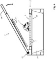
- FIG. 1 shows an embodiment of a food shredder according to the invention in a first Aufstellauscardi for using a first crushing tool 1.
- the food shredder has a base part 2, which has the outer contour of a cuboid as an outer contour.
- the base part 2 carries a removable cutting part 3, which has a plurality of cutting blades 4.
- On the base part also an operating part 5 is articulated, which is for pressing through to shred food by the cutting part 3 from an insertion position against the cutting part 3 in a closed position and then again from the closed position into the insertion position.
- the cutting part 3 and the actuating part are components of the first crushing tool 1.
- On the base part are further crushing tools, namely a Feinreibe 6, a coarse grater 7 and arranged on the bottom of a planer 8. Through an opening 9 in the square end face of the base part 2, a collecting container 10 can be inserted.
- the collecting container 10 is preferably always inserted so that its filling opening 11 faces the particular crushing tool to be used and directed upwards. In the erecting orientation of the base part shown, the collecting container is introduced in such a way that its filling opening faces the cutting part 3, so that the foodstuff pressed and crushed by the cutting part automatically falls into the collecting container 10.
- the collecting container 10 is first removed from the base part 2, the base part rotated so that the used further crushing tool is oriented upward, and then the collecting container 10 again with its filling opening introduced upwards.
- FIG. 3 shows this by way of example in relation to the use of the planer as 8 further crushing tool.
- FIG. 2 shows the food grinder with removed Feinreibe 6 and removed Grobreibe 7.
- FIG. 2 is also in this Aufstellauscardi down, formed in the form of a planer 8 further crushing tool, a planing blade 12 and a, in particular in FIG. 3 good to be recognized, slide 13 has visible.
- the base part 2 has, on the end face opposite the end face with the insertion opening 9, a window 14, by means of which the fill level of the preferably transparent collecting container 10 can be checked without the collecting container 10 having to be removed from the base part 2.
- the base part 2 preferably has at its corners in each case one in all three spatial directions protruding foot. However, the feet are not shown for the sake of clarity.
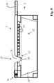
- FIG. 4 shows another example of a Food crusher during a crushing operation in a sectional view.
- the further comminution tools which are arranged on the surfaces of the base part 2, are not shown for the sake of clarity.
- Food crusher shown has a base part 2, which has a receptacle 15 for a cutting part 3.
- the base part 2 is connected in such an articulated manner to an actuating part 5 by means of a hinge connection 16 that the actuating part 5 can be pivoted against the cutting part 3 in order to force feed 17 to be crushed through.
- the cutting part 3 has a plurality of cutting blades 4, immersed between the ram 35 of the operating part 5 during the crushing process.
- a handle 18 is arranged at the free end of the actuating part 5.
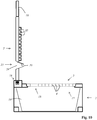
- FIG. 5 shows the device at the beginning of a de-stoning process.
- the actuating part 5 has been replaced by a further actuating part 19, which has a Ausdrückdorn 24.
- the articulated connection 16 of the actuating part 5 with the base part 2 was released and instead the further actuating part 19 hingedly connected to the base part 2.
- a stone fruit holder 20 which is designed to hold a piece of stone fruit 21, such as, for example, a cherry 22, which has a stone 23 to be pressed out, in a de-stoning position, was inserted into the receptacle 15.
- the further actuating part 19 is pivoted in the direction of the base part 2, so that the stone 23 of the piece of stone fruit 21 held by the stone fruit holder 20 is pushed out of the stone fruit 21 by the pivoting movement of the Ausd Wegdornes 24 relative to the stone fruit holder 20, which in FIG. 6 is shown.
- the pushed-out stone 23 falls into the collecting container 10.
- the further actuating member 19 again pivoted upward and the stoned piece of stone fruit 21 are removed.
- FIG. 7 shows another example of a device in which the Ausd Wegdorn 24 is attached to perform a de-stoning process on the base part 5, which has the press ram 35, by means of a connector, not shown.
- the Entsteinungsvorgang itself takes place in this embodiment, analogously, as it in the Figures 5 and 6 is shown.
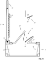
- FIG. 8 shows a fourth example of a food crusher converted for cutting spiral garlands.
- the fourth embodiment may be designed in particular as the in Fig. 4 illustrated embodiment.
- the cutting part 3 has been removed from the receptacle 15 and instead a spiral cutter 25 is inserted into the receptacle 15 in the manner of a sharpener.
- the spiral cutter 25 has a holding plate 27, which has the same outer contour in terms of shape and size as the cutting part 3. This allows the spiral cutter 25 - without additional fixing components are required - temporarily set instead of the cutting part 3 in the receptacle 15 of the base part 2 , In the holding plate 27 of the spiral cutter 25, a further spiral cutter 26 is also held.
- the spiral cutter 25 has a conical receiving space 28 for introducing food items, such as a carrot of a radish or a cucumber, on whose wall a cutting blade 29 is arranged.
- food items such as a carrot of a radish or a cucumber
- a cutting blade 29 is arranged.
- the wall of the receiving space 28 has an opening (not shown) through which the spiral-shaped garland can emerge from the receiving space 28.
- the spiral garland is automatically collected in the collecting container 10.
- the further spiral cutter 26 in the manner of a sharpener has a different size than the spiral cutter 25.
- the further receiving space 30 of the other spiral cutter 26 has a different wedge angle than the receiving space 28 of the spiral cutter 25.
- a further cutting blade 31 projecting into the further receiving space 30 is arranged, which separates a spiral garland (not shown) from a food item which is rotated in the further receiving space about the rotation central axis of the further receiving space 30.
- the wall of the further receiving space 30 has an opening through which the separated there spiral garland can emerge from the further receiving space 30 and thus enters the collecting container 10.
- the Figures 9 and 10 show a fifth example of a food crusher designed to cut spiral garlands.
- the spiral cutter 25 is arranged in the manner of a Anspitzers in the operating part 5.
- the actuating part 5 has a first section with press dies 35, which serve to press food to be ground by a cutting part 3 provided with cutting edge blades 4, by pivoting the actuating part 5 against the cutting part 3.
- the spiral cutter 25 is in a second section of the operating part 5 arranged.
- the cutting part 3 has in this embodiment, a through hole 32 which is free of cutting edge blades 4. A part of the spiral cutter 25 protrudes through the passage opening 32 when the actuating part 5 is closed. In addition, the (not shown) bringsspante spiral spiral garland pass through the passage opening 32 into the collecting container 10.
- the spiral cutter 25 has a conical receiving space 28 for introducing food items, such as a carrot of a radish or a cucumber, on whose wall a cutting blade 29 is arranged.
- food items such as a carrot of a radish or a cucumber
- the wall of the receiving space 28 has an opening (not shown) through which the spiral-shaped garland can emerge from the receiving space 28.
- Fig. 11 shows a fifth example of a food crusher designed to cut spiral garlands.
- the spiral cutter 25 a holding plate 27 into which optionally at least one of a plurality of different cutting inserts 33 can be inserted.
- the cutting inserts 33 each have a conical, receiving space 28 for the introduction of food, on whose wall in each case a cutting blade 29 is arranged and in which the food is rotatable.
- the cutting inserts 33 may be in particular with respect to their shape and / or size and / or in relation to the thickness and / or width of the spirally shaped garlands which can be cut with them and / or with respect to the number of simultaneously Cutting spiral resulting garlands differ.
- the cutting insert 33 used in each case in the holding plate 27, for example, by means of a locking device or a bayonet mount, in particular without tools, are set releasably again.
- the holding plate 27 has the same outer contour in terms of shape and size as an insertable into the receptacle cutting part 3. This allows the spiral cutter 25 - without additional fixation components are required - temporarily set instead of a cutting part 3 in the receptacle 15 of the base part 2.
- the holding plate has a cylindrical projection 34, in each of which a cutting insert 33 can be inserted.
Landscapes
- Engineering & Computer Science (AREA)
- Mechanical Engineering (AREA)
- Life Sciences & Earth Sciences (AREA)
- Forests & Forestry (AREA)
- Food Science & Technology (AREA)
- Food-Manufacturing Devices (AREA)
- General Preparation And Processing Of Foods (AREA)
- Crushing And Pulverization Processes (AREA)
Claims (15)
- Dispositif de broyage des aliments, lequel présente une partie de base (2), un premier outil de broyage (1), au moins un autre outil de broyage ainsi qu'un bac de récupération (10) pour la matière alimentaire broyée, et pour lequel au moins un outil de broyage ou au moins une partie de l'un des outils de broyage est mis(e) en place, ou peut être mis (e) en place de manière à pouvoir être retirée de nouveau, au niveau de la partie de base (2), caractérisé en ce que le bac de récupération (10) peut être disposé dans la partie de base (2), ce de manière sélective dans une première position de rotation, dans laquelle il recueille la matière alimentaire broyée au moyen du premier outil de broyage, d'une part, ou dans une deuxième position de rotation, laquelle est différente de la première position de rotation, dans laquelle il recueille la matière alimentaire broyée au moyen du deuxième outil de broyage, d'autre part.
- Dispositif de broyage des aliments selon la revendication 1, caractérisé en ce que la partie de base (2) supporte une pièce de coupe (3) et caractérisé en ce que le dispositif destiné à broyer des aliments présente une pièce de manoeuvre (5) mise en place de manière articulée, en particulier au niveau de la partie de base (2), laquelle pièce de manoeuvre est capable de pivoter, en vue de pousser de la matière alimentaire devant être broyée à travers la pièce de coupe (3), à partir d'une position d'insertion contre la pièce de coupe (3) dans une position de fermeture, d'une part, puis en sens inverse, de la position de fermeture dans la position d'insertion, la pièce de coupe (3) et la pièce de manoeuvre (5) étant des parties intégrantes du premier outil de broyage.
- Dispositif de broyage des aliments selon la revendication 1 ou 2, caractérisé en ce que la partie de base (2) est une partie intégrante de l'autre outil de broyage et / ou l'au moins un autre outil de broyage est mis en place au niveau de la partie de base (2).
- Dispositif de broyage des aliments selon l'une des revendications 1 à 3, caractérisé en ce que :a. le dispositif de broyage des aliments présente une trancheuse (8) qui fait partie de l'un des autres outils de broyage ; et / ou en ce queb. le dispositif de broyage des aliments présente une râpe qui fait partie de l'un des autres outils de broyage ; et / ou en ce quec. le dispositif de broyage des aliments présente une grosse râpe (7) qui fait partie de l'un des autres outils de broyage ; et / ou en ce qued. le dispositif de broyage des aliments présente une râpe fine (6) qui fait partie de l'un des autres outils de broyage ; et / ou en ce quee. le dispositif de broyage des aliments présente une lame à découper en spirale, en particulier du type d'un taille-crayon, qui fait partie de l'un des autres outils de broyage ; et / ou en ce quef. le dispositif de broyage des aliments présente un système de dénoyauteur, destiné au dénoyautage des fruits à noyau et qui fait partie de l'un des autres outils de broyage.
- Dispositif de broyage des aliments selon l'une des revendications 1 à 4, caractérisé en ce que :a. l'autre outil de broyage est formé de parties qui sont différentes de la pièce de coupe (3) et de la pièce de manoeuvre (5) ; ou en ce queb. l'au moins un autre outil de broyage ne possède aucune partie en commun avec le premier outil de broyage ; ou en ce quec. la partie de base (2) est, en même temps, aussi bien une partie intégrante du premier outil de broyage qu'une partie intégrante de l'autre outil de broyage ; ou en ce qued. l'au moins un autre outil de broyage possède exclusivement la partie de base (2) en commun avec le premier outil de broyage ; ou en ce quee. le premier outil et / ou l'autre outil de broyage sont mis en place ou peuvent être mis en place au niveau de la partie de base (2), de préférence sans outil et de manière non destructive, de manière à pouvoir être retirés de nouveau ; ou en ce quef. les outils de broyage peuvent être utilisés indépendamment les uns des autres.
- Dispositif de broyage des aliments selon l'une des revendications 1 à 5, caractérisé en ce que :a. la partie de base (2) est conçue en tant que polyèdre et / ou en tant que contour extérieur qui présente un polyèdre ; ou en ce queb. la partie de base (2) est conçue en tant que parallélépipède et / ou en tant que contour extérieur qui présente un parallélépipède ; et / ou en ce quec. la partie de base (2) est conçue en tant que châssis, lequel présente le contour d'un polyèdre en tant que contour extérieur ; et / ou en ce qued. la partie de base (2) est conçue en tant que châssis, lequel présente le contour d'un parallélépipède en tant que contour extérieur.
- Dispositif de broyage des aliments selon la revendication 6, caractérisé en ce que :a. les outils de broyage sont disposés ou peuvent être disposés de manière séparée les uns des autres, respectivement au niveau de l'une et dans l'une des diverses surfaces de la partie de base ; et / ou en ce queb. au moins un outil de broyage est disposé au niveau de l'une ou dans l'une des diverses surfaces de la partie de base et la surface se trouvant à l'opposé de la surface est conçue comme une surface de montage, pourvue en particulier de pieds de support, sur laquelle la partie de base (2) peut être installée en vue de l'utilisation de l'outil de broyage ; et / ou en ce quec. au moins un outil de broyage est disposé au niveau de l'une ou dans l'une des diverses surfaces de la partie de base et la surface se trouvant à l'opposé de la surface est conçue comme une surface de montage, pourvue en particulier de pieds de support, sur laquelle la partie de base (2) peut être installée en vue de l'utilisation de l'outil de broyage, la surface de montage présentant un autre outil de broyage.
- Dispositif de broyage des aliments selon l'une des revendications 1 à 7, caractérisé en ce que :a. au moins un outil de broyage ou au moins une partie de l'un des outils de broyage est mis (e) en place ou peut être mis (e) en place de manière amovible, sans outil et / ou de manière non destructive, au niveau de la partie de base (2) ; et / ou en ce queb. plusieurs outils de broyage ou respectivement au moins des parties des différents outils de broyage sont mis(es) en place ou peuvent être mis(es) en place, en particulier indépendamment les un(e)s des autres, de manière amovible au niveau de la partie de base (2) ; et / ou en ce quec. au moins un autre outil de broyage ou au moins une partie d'un autre outil de broyage est mis (e) en place ou peut être mis (e) en place de manière amovible au niveau de la partie de base (2) ; et / ou en ce qued. au moins un élément d'encliquetage est présent en vue de la mise en place de manière amovible de l'outil de broyage ou de l'autre outil de broyage ou d'une partie de l'outil de broyage ou d'une partie de l'autre outil de broyage ; et / ou en ce quee. un dispositif de verrouillage est présent, au moyen duquel la pièce de manoeuvre (5) peut être fixée dans la position de fermeture ; et / ou en ce quef. au moins un outil de broyage est disposé de manière inamovible au niveau de la partie de base (2) ou est fabriqué, tout au moins en partie, d'une seule pièce avec la partie de base (2).
- Dispositif de broyage des aliments selon l'une des revendications 1 à 8, caractérisé en ce que :a. le dispositif de broyage des aliments présente un support pour fruits à noyau en vue de maintenir en place au moins un fruit à noyau et présente au moins un mandrin d'éjection, de telle sorte que le noyau d'un fruit à noyau maintenu en place par le support pour fruits à noyau peut être extrait hors du fruit à noyau par un mouvement de pivotement du mandrin d'éjection par rapport au support pour fruits à noyau ; ou en ce queb. le dispositif de broyage des aliments présente un support pour fruits à noyau en vue de maintenir en place au moins un fruit à noyau et présente au moins un mandrin d'éjection, de telle sorte que le noyau d'un fruit à noyau maintenu en place par le support pour fruits à noyau peut être extrait hors du fruit à noyau par un mouvement de pivotement du mandrin d'éjection par rapport au support pour fruits à noyau, le mandrin d'éjection étant mis en place au niveau de la pièce de manoeuvre ou pouvant être mis en place au niveau de la pièce de manoeuvré ; ou en ce quec. le dispositif de broyage des aliments présente un support pour fruits à noyau en vue de maintenir en place au moins un fruit à noyau et présente au moins un mandrin d'éjection, de telle sorte que le noyau d'un fruit à noyau maintenu en place par le support pour fruits à noyau peut être extrait hors du fruit à noyau par un mouvement de pivotement du mandrin d'éjection par rapport au support pour fruits à noyau, une autre pièce de manoeuvre étant présente, laquelle présente le mandrin d'éjection et laquelle peut être mise en place de manière articulée au niveau de la partie de base (2) au lieu de la pièce de manoeuvré.
- Dispositif selon l'une des revendications 1 à 9, caractérisé en ce que :a. la partie de base (2) présente un logement, dans laquelle la pièce de coupe (3) ou un support pour fruits à noyau ou une lame à découper en spirale peut être inséré(e) de manière sélective, en particulier dans un parfait ajustement et / ou par un mécanisme d'encliquetage ; et / ou en ce queb. la partie de base (2) présente un logement, dans laquelle la pièce de coupe (3) ou un support pour fruits à noyau ou une lame à découper en spirale peut être inséré(e) de manière sélective, en particulier dans un parfait ajustement et / ou par un mécanisme d'encliquetage, la lame à découper en spirale présentant une plaque de retenue qui, au regard de la forme et de la taille, présente le même contour extérieur que la pièce de coupe (3) et / ou caractérisé en ce que le support pour fruits à noyau présente une plaque de retenue qui, au regard de la forme et de la taille, présente le même contour extérieur que la pièce de coupe (3).
- Dispositif de broyage des aliments selon l'une des revendications 1 à 10, caractérisé en ce que :a. la partie de base (2) présente un logement pour le bac de récupération (10), lequel logement présente une dispositif de fixation destiné à la mise en place provisoire du bac de récupération ; et / ou en ce queb. le bac de récupération (10) peut être disposé, en particulier peut être inséré dans la partie de base (2) de telle sorte qu'il recueille automatiquement la matière alimentaire broyée ; et / ou en ce quec. la partie de base (2) présente au moins un regard (14), au travers duquel le bac de récupération (10) disposé dans la partie de base (2) et / ou le niveau de remplissage du bac de récupération disposé dans la partie de base (2) peuvent être observés.
- Dispositif de broyage des aliments selon l'une des revendications 1 à 11, caractérisé en ce que :a. le dispositif de broyage des aliments est conçu en ce sens qu'il peut être positionné sur un plan de travail, par exemple sur une surface de table de cuisine, pour un processus de broyage des aliments ; et / ou en ce queb. le dispositif de broyage des aliments est conçu en ce sens qu'il peut être positionné de manière sélective dans une orientation de positionnement parmi les plusieurs orientations de positionnement différentes possibles, sur un plan de travail, par exemple sur une surface de table de cuisine, pour un processus de broyage des aliments ; et / ou en ce quec. le dispositif de broyage des aliments est conçu en ce sens qu'il peut être utilisé sur un plan de travail, par exemple sur une surface de table de cuisine, en positionnant le premier outil de broyage dans une première orientation de positionnement pour un processus de broyage des aliments, d'une part, et en positionnant l'autre outil de broyage dans une autre orientation de positionnement, qui est différente de la première orientation de positionnement, pour un processus de broyage des aliments, d'autre part ;d. une orientation de positionnement parmi les plusieurs orientations de positionnement différentes possibles est associée à chaque outil de broyage et caractérisé en ce que le dispositif de broyage des aliments est conçu en ce sens qu'il peut être utilisé sur un plan de travail, par exemple sur une surface de table de cuisine, en positionnant l'un des outils de broyage dans l'orientation de positionnement associée à l'outil de broyage, pour un processus de broyage des aliments.
- Dispositif de broyage des aliments selon l'une des revendications 1 à 12, caractérisé en ce que :a. le dispositif de broyage des aliments présente des pieds de support destinés au positionnement du dispositif de broyage des aliments dans diverses orientations de positionnement ; et / ou en ce queb. la partie de base (2) présente des pieds de support ; et / ou en ce quec. des pieds de support sont présents, lesquels sont fabriqués en un matériau élastique et / ou en un matériau dotée d'une friction élevée par adhérence, en particulier un matériau en caoutchouc ; et / ou en ce qued. la partie de base (2) présente des pieds de support faisant saillie par rapport aux outils de broyage.
- Dispositif de broyage des aliments selon la revendication 13, caractérisé en ce que :a. au moins un pied de support est disposé de telle sorte qu'il peut être utilisé pour différentes orientations de positionnement ; et / ou en ce queb. les pieds de support sont disposés au niveau des bords et / ou le long des bords de la partie de base, conçue en particulier en tant que polyèdre ou en tant que parallélépipède ; et / ou en ce quec. les pieds de support sont disposés aux coins de la partie de base, conçue en particulier en tant que polyèdre ou en tant que parallélépipède ; et / ou en ce qued. la partie de base (2) présente des pieds de support qui servent exclusivement au positionnement dans une seule orientation de positionnement parmi les diverses orientations de positionnement possibles ; et / ou en ce quee. la partie de base (2) présente des pieds de support sur au moins l'une de ses surfaces.
- Dispositif de broyage des aliments selon l'une des revendications 1 à 14, caractérisé en ce que :a. la partie de base (2) est fabriquée en tant que pièce moulée par injection, en particulier en tant que pièce en plastique moulée par injection, ou caractérisé en ce que la partie de base (2) présente au moins une partie fabriquée en tant que pièce moulée par injection, en particulier en tant que pièce en plastique moulée par injection, ou caractérisé en ce que la partie de base (2) est constituée de plusieurs parties fabriquées, en particulier en tant que pièces moulées par injection, en particulier en tant que pièces en plastique moulées par injection ; et / ou en ce queb. la partie de base (2) présente le contour d'un parallélépipède en tant que contour extérieur et caractérisé en ce qu'une ouverture destinée à l'insertion d'un bac de récupération est présente au niveau d'une surface frontale et caractérisé en ce que la pièce de coupe (3) est disposée au niveau de l'une des surfaces latérales qui est voisine de la surface frontale, et caractérisé en ce qu'un autre outil de broyage est disposé respectivement au niveau des autres surfaces latérales qui sont voisines de la surface frontale.
Priority Applications (1)
| Application Number | Priority Date | Filing Date | Title |
|---|---|---|---|
| SI201530085T SI3013540T1 (sl) | 2014-06-12 | 2015-06-12 | Naprava za rezanje živil |
Applications Claiming Priority (2)
| Application Number | Priority Date | Filing Date | Title |
|---|---|---|---|
| DE102014108266.4A DE102014108266A1 (de) | 2014-06-12 | 2014-06-12 | Lebensmittelzerkleinerungsvorrichtung |
| PCT/EP2015/063159 WO2015189382A1 (fr) | 2014-06-12 | 2015-06-12 | Dispositif de broyage d'aliments |
Publications (2)
| Publication Number | Publication Date |
|---|---|
| EP3013540A1 EP3013540A1 (fr) | 2016-05-04 |
| EP3013540B1 true EP3013540B1 (fr) | 2017-05-17 |
Family
ID=53385650
Family Applications (1)
| Application Number | Title | Priority Date | Filing Date |
|---|---|---|---|
| EP15728535.4A Not-in-force EP3013540B1 (fr) | 2014-06-12 | 2015-06-12 | Appareil pour couper des alliments en petits morceaux |
Country Status (12)
| Country | Link |
|---|---|
| US (1) | US20160158956A1 (fr) |
| EP (1) | EP3013540B1 (fr) |
| JP (1) | JP2016534886A (fr) |
| CN (2) | CN204546633U (fr) |
| AU (1) | AU2015273435B2 (fr) |
| CA (1) | CA2951342C (fr) |
| DE (1) | DE102014108266A1 (fr) |
| HK (1) | HK1219462A1 (fr) |
| MX (1) | MX2016015927A (fr) |
| NZ (1) | NZ726786A (fr) |
| SI (1) | SI3013540T1 (fr) |
| WO (1) | WO2015189382A1 (fr) |
Families Citing this family (12)
| Publication number | Priority date | Publication date | Assignee | Title |
|---|---|---|---|---|
| CN204546632U (zh) * | 2014-06-12 | 2015-08-12 | 杰尼斯有限责任公司 | 食物切割装置 |
| CA162251S (en) | 2014-11-07 | 2016-11-24 | Genius Gmbh | Cutting device |
| DE102015109402A1 (de) * | 2015-06-12 | 2016-12-15 | Genius Gmbh | Vorrichtung zum Zerkleinern von Lebensmitteln |
| DE102015109401B4 (de) * | 2015-06-12 | 2018-05-24 | Genius Gmbh | Vorrichtung zum Zerkleinern von Lebensmitteln und zum Entsteinen von Steinobst sowie Küchengerät mit einer solchen Vorrichtung |
| CN106073555A (zh) * | 2016-08-19 | 2016-11-09 | 宁波众海电器有限公司 | 一种多功能厨用刨刀 |
| US10750909B2 (en) * | 2017-03-16 | 2020-08-25 | Progressive International Corporation | Grater |
| US10806151B2 (en) * | 2017-05-16 | 2020-10-20 | Eve Horne | Device and method for shaping baked goods |
| CN107242814A (zh) * | 2017-07-06 | 2017-10-13 | 吴肖颜 | 一种削丝器 |
| USD854893S1 (en) * | 2017-07-17 | 2019-07-30 | Joseph Joseph, Ltd. | Grater with collecting base |
| USD838146S1 (en) * | 2017-12-26 | 2019-01-15 | Helen Of Troy Limited | Slicer and grater storage container |
| US11286669B2 (en) * | 2018-03-19 | 2022-03-29 | Quail Manufacturing, LLC | Shingle cutting machine |
| USD1034107S1 (en) * | 2024-03-08 | 2024-07-09 | Huangshi Fusun Trade Co., Ltd. | Vegetable grater |
Family Cites Families (35)
| Publication number | Priority date | Publication date | Assignee | Title |
|---|---|---|---|---|
| GB189827111A (en) * | 1898-12-22 | 1899-10-28 | Edward Howe | An Improved Grater and Slicer. |
| US1922973A (en) * | 1932-01-07 | 1933-08-15 | Stephen A Mischanski | Grater |
| US2615486A (en) * | 1950-01-14 | 1952-10-28 | Marcus William | Vegetable grater |
| JPS4943639Y2 (fr) * | 1971-10-19 | 1974-11-29 | ||
| GB1360308A (en) * | 1972-02-22 | 1974-07-17 | Gunsons Sortex Ltd | Fruit pitting machine |
| US3848524A (en) * | 1972-10-10 | 1974-11-19 | Dynamics Corp America | Apparatus for peeling vegetables |
| DE2704384A1 (de) * | 1977-01-31 | 1978-08-03 | Hans Joachim Klama | Universal-haushaltsgeraet erstmalig auch zum schnittlauchschneiden |
| DK144848C (da) * | 1978-04-19 | 1982-11-08 | Leifheit International | Apparat til findeling af naeringsmidler |
| JPS6044744U (ja) * | 1983-08-31 | 1985-03-29 | 鈴木 元 | 野菜類調理器 |
| JPH01156895U (fr) * | 1988-04-22 | 1989-10-27 | ||
| US4928893A (en) * | 1989-04-10 | 1990-05-29 | Robinson Knife Manufacturing Co., Inc. | Food processor |
| USD343098S (en) * | 1990-10-05 | 1994-01-11 | Ki Mee Metal & Plastic Factory Limited | Grating tool |
| US5097735A (en) * | 1991-05-06 | 1992-03-24 | Mendenhall George A | Helical spiral food product and apparatus for making the same |
| US5711491A (en) * | 1995-12-19 | 1998-01-27 | Dart Industries Inc. | Food grater |
| US5692424A (en) * | 1996-01-03 | 1997-12-02 | Wallace; Stephen C. | Food slicer |
| US5745999A (en) * | 1996-12-09 | 1998-05-05 | Zirkiev; Arkady | Food slicer device |
| US5979281A (en) * | 1998-02-23 | 1999-11-09 | Caesar; Wayne W | Produce slicer and chopper device |
| DE19827077A1 (de) * | 1998-06-18 | 1999-12-23 | Leifheit Ag | Vorrichtung zum Zerkleinern von Lebensmitteln |
| US5960709A (en) * | 1999-01-08 | 1999-10-05 | Yip; Chung Lun | Food processor |
| ATE504403T1 (de) | 2004-10-29 | 2011-04-15 | Progressive Int Corp | Zerhackvorrichtung für lebensmittel |
| DE102005011310B4 (de) * | 2005-03-08 | 2008-10-23 | Börner Kunststoff- und Metallwarenfabrik GmbH | Mehrfachreibe |
| CN101088723B (zh) * | 2006-06-16 | 2010-09-22 | 进步国际有限公司 | 食物切碎器 |
| US7946222B2 (en) * | 2008-02-05 | 2011-05-24 | Nicholas Webb | Food item press |
| US8371199B2 (en) * | 2008-04-25 | 2013-02-12 | Shankar Raj Ghimire | Smart food chopper |
| CN201205229Y (zh) * | 2008-05-22 | 2009-03-11 | 刘伟国 | 一种食物切碎器 |
| US8347783B2 (en) * | 2009-02-12 | 2013-01-08 | Progressive International Corporation | Cherry pitter |
| DE102009023167A1 (de) * | 2009-05-29 | 2010-12-02 | Cedomir Repac | Vorrichtung zum Schneiden von Nahrungsmitteln sowie Multifunktionsgerät für die Küche |
| DE202009011687U1 (de) | 2009-09-03 | 2009-11-26 | Allegro Commercial Gmbh | Küchenhobel |
| US20110111101A1 (en) * | 2009-11-06 | 2011-05-12 | Graham Packaging Company, L.P. | Method and apparatus of packaging beverage mixture |
| US8574043B2 (en) * | 2011-03-07 | 2013-11-05 | Samuel G. Zean | Multifunctional food preparation apparatus |
| DE202011050041U1 (de) | 2011-05-05 | 2011-07-14 | Cedomir Repac | Schneideinsatz für eine Lebensmittelzerkleinerungsvorrichtung |
| CN202357193U (zh) * | 2011-11-15 | 2012-08-01 | 刘伟国 | 两用切削器 |
| US20130233952A1 (en) * | 2012-03-08 | 2013-09-12 | Hamilton Beach Brands, Inc. | Kitchen Appliance for Processing Foodstuff and Method of Operating Same |
| CN102599830A (zh) * | 2012-03-16 | 2012-07-25 | 台州市双马塑业有限公司 | 多功能食物处理器 |
| DE102012211360B4 (de) * | 2012-06-29 | 2015-11-12 | Wmf Württembergische Metallwarenfabrik Ag | Vierkantreibe |
-
2014
- 2014-06-12 DE DE102014108266.4A patent/DE102014108266A1/de not_active Withdrawn
- 2014-11-07 CN CN201420679559.7U patent/CN204546633U/zh not_active Expired - Fee Related
- 2014-11-07 CN CN201410642867.7A patent/CN105291167A/zh active Pending
-
2015
- 2015-06-12 EP EP15728535.4A patent/EP3013540B1/fr not_active Not-in-force
- 2015-06-12 NZ NZ726786A patent/NZ726786A/en not_active IP Right Cessation
- 2015-06-12 JP JP2016516006A patent/JP2016534886A/ja active Pending
- 2015-06-12 US US14/905,294 patent/US20160158956A1/en not_active Abandoned
- 2015-06-12 SI SI201530085T patent/SI3013540T1/sl unknown
- 2015-06-12 WO PCT/EP2015/063159 patent/WO2015189382A1/fr active Application Filing
- 2015-06-12 AU AU2015273435A patent/AU2015273435B2/en not_active Ceased
- 2015-06-12 MX MX2016015927A patent/MX2016015927A/es unknown
- 2015-06-12 CA CA2951342A patent/CA2951342C/fr not_active Expired - Fee Related
-
2016
- 2016-06-29 HK HK16107599.2A patent/HK1219462A1/zh unknown
Also Published As
| Publication number | Publication date |
|---|---|
| MX2016015927A (es) | 2017-05-23 |
| AU2015273435B2 (en) | 2018-01-04 |
| AU2015273435A1 (en) | 2016-12-15 |
| EP3013540A1 (fr) | 2016-05-04 |
| CN105291167A (zh) | 2016-02-03 |
| SI3013540T1 (sl) | 2017-09-29 |
| NZ726786A (en) | 2018-03-23 |
| HK1219462A1 (zh) | 2017-04-07 |
| US20160158956A1 (en) | 2016-06-09 |
| DE102014108266A1 (de) | 2015-12-17 |
| CA2951342C (fr) | 2018-07-10 |
| JP2016534886A (ja) | 2016-11-10 |
| CA2951342A1 (fr) | 2015-12-17 |
| CN204546633U (zh) | 2015-08-12 |
| WO2015189382A1 (fr) | 2015-12-17 |
Similar Documents
| Publication | Publication Date | Title |
|---|---|---|
| EP3013540B1 (fr) | Appareil pour couper des alliments en petits morceaux | |
| EP3013201B1 (fr) | Dispositif de broyage d'aliments | |
| EP3057744A1 (fr) | Dispositif de broyage d'aliments | |
| EP2938800B9 (fr) | Dispositif de broyage de denrées alimentaires | |
| EP3307501B1 (fr) | Dispositif pour la découpe d'aliments | |
| EP3010383B1 (fr) | Dispositif de broyage de denrées alimentaires | |
| EP3307500B1 (fr) | Système de coupe pour couper des fruits ou des légumes en guirlandes spiralées | |
| DE102015109401B4 (de) | Vorrichtung zum Zerkleinern von Lebensmitteln und zum Entsteinen von Steinobst sowie Küchengerät mit einer solchen Vorrichtung | |
| EP2641515A1 (fr) | Découpeur de pulpe de fruit | |
| EP3725476B1 (fr) | Système de broyage de denrées alimentaires | |
| EP3725474B1 (fr) | Système de broyage des denrées alimentaires | |
| DE102008028666A1 (de) | Zerkleinerungsvorrichtung für Lebensmittel | |
| DE202014102724U1 (de) | Lebensmittelzerkleinerungsvorrichtung | |
| DE102017223183B4 (de) | Bearbeitungsvorrichtung für die Zerkleinerung von Verarbeitungsgut | |
| LU101188B1 (de) | Lebensmittelzerkleinerungssystem | |
| LU101186B1 (de) | Lebensmittelzerkleinerungssystem | |
| EP4129590A1 (fr) | Dispositif broyeur de denrées alimentaires | |
| DE2841625A1 (de) | Vorrichtung zum zerkleinern von nahrungsmitteln, insbesondere obst und gemuese | |
| DE20006089U1 (de) | Vorrichtung zum Schneiden von dünnen, stangenförmigem Gemüse | |
| DE3604950A1 (de) | Hand-kuechengeraet | |
| DE1687741U (de) | Geraet zum zerkleinern von zwiebeln. |
Legal Events
| Date | Code | Title | Description |
|---|---|---|---|
| PUAI | Public reference made under article 153(3) epc to a published international application that has entered the european phase |
Free format text: ORIGINAL CODE: 0009012 |
|
| 17P | Request for examination filed |
Effective date: 20160127 |
|
| AK | Designated contracting states |
Kind code of ref document: A1 Designated state(s): AL AT BE BG CH CY CZ DE DK EE ES FI FR GB GR HR HU IE IS IT LI LT LU LV MC MK MT NL NO PL PT RO RS SE SI SK SM TR |
|
| AX | Request for extension of the european patent |
Extension state: BA ME |
|
| 17Q | First examination report despatched |
Effective date: 20160527 |
|
| GRAP | Despatch of communication of intention to grant a patent |
Free format text: ORIGINAL CODE: EPIDOSNIGR1 |
|
| INTG | Intention to grant announced |
Effective date: 20161220 |
|
| GRAS | Grant fee paid |
Free format text: ORIGINAL CODE: EPIDOSNIGR3 |
|
| GRAA | (expected) grant |
Free format text: ORIGINAL CODE: 0009210 |
|
| DAV | Request for validation of the european patent (deleted) | ||
| DAX | Request for extension of the european patent (deleted) | ||
| AK | Designated contracting states |
Kind code of ref document: B1 Designated state(s): AL AT BE BG CH CY CZ DE DK EE ES FI FR GB GR HR HU IE IS IT LI LT LU LV MC MK MT NL NO PL PT RO RS SE SI SK SM TR |
|
| REG | Reference to a national code |
Ref country code: GB Ref legal event code: FG4D Free format text: NOT ENGLISH |
|
| REG | Reference to a national code |
Ref country code: CH Ref legal event code: EP |
|
| REG | Reference to a national code |
Ref country code: IE Ref legal event code: FG4D Free format text: LANGUAGE OF EP DOCUMENT: GERMAN |
|
| REG | Reference to a national code |
Ref country code: AT Ref legal event code: REF Ref document number: 894051 Country of ref document: AT Kind code of ref document: T Effective date: 20170615 |
|
| REG | Reference to a national code |
Ref country code: FR Ref legal event code: PLFP Year of fee payment: 3 |
|
| REG | Reference to a national code |
Ref country code: DE Ref legal event code: R096 Ref document number: 502015001092 Country of ref document: DE |
|
| REG | Reference to a national code |
Ref country code: NL Ref legal event code: FP |
|
| REG | Reference to a national code |
Ref country code: LT Ref legal event code: MG4D |
|
| PG25 | Lapsed in a contracting state [announced via postgrant information from national office to epo] |
Ref country code: HR Free format text: LAPSE BECAUSE OF FAILURE TO SUBMIT A TRANSLATION OF THE DESCRIPTION OR TO PAY THE FEE WITHIN THE PRESCRIBED TIME-LIMIT Effective date: 20170517 Ref country code: ES Free format text: LAPSE BECAUSE OF FAILURE TO SUBMIT A TRANSLATION OF THE DESCRIPTION OR TO PAY THE FEE WITHIN THE PRESCRIBED TIME-LIMIT Effective date: 20170517 Ref country code: LT Free format text: LAPSE BECAUSE OF FAILURE TO SUBMIT A TRANSLATION OF THE DESCRIPTION OR TO PAY THE FEE WITHIN THE PRESCRIBED TIME-LIMIT Effective date: 20170517 Ref country code: GR Free format text: LAPSE BECAUSE OF FAILURE TO SUBMIT A TRANSLATION OF THE DESCRIPTION OR TO PAY THE FEE WITHIN THE PRESCRIBED TIME-LIMIT Effective date: 20170818 Ref country code: NO Free format text: LAPSE BECAUSE OF FAILURE TO SUBMIT A TRANSLATION OF THE DESCRIPTION OR TO PAY THE FEE WITHIN THE PRESCRIBED TIME-LIMIT Effective date: 20170817 Ref country code: FI Free format text: LAPSE BECAUSE OF FAILURE TO SUBMIT A TRANSLATION OF THE DESCRIPTION OR TO PAY THE FEE WITHIN THE PRESCRIBED TIME-LIMIT Effective date: 20170517 |
|
| PG25 | Lapsed in a contracting state [announced via postgrant information from national office to epo] |
Ref country code: IS Free format text: LAPSE BECAUSE OF FAILURE TO SUBMIT A TRANSLATION OF THE DESCRIPTION OR TO PAY THE FEE WITHIN THE PRESCRIBED TIME-LIMIT Effective date: 20170917 Ref country code: PL Free format text: LAPSE BECAUSE OF FAILURE TO SUBMIT A TRANSLATION OF THE DESCRIPTION OR TO PAY THE FEE WITHIN THE PRESCRIBED TIME-LIMIT Effective date: 20170517 Ref country code: LV Free format text: LAPSE BECAUSE OF FAILURE TO SUBMIT A TRANSLATION OF THE DESCRIPTION OR TO PAY THE FEE WITHIN THE PRESCRIBED TIME-LIMIT Effective date: 20170517 Ref country code: RS Free format text: LAPSE BECAUSE OF FAILURE TO SUBMIT A TRANSLATION OF THE DESCRIPTION OR TO PAY THE FEE WITHIN THE PRESCRIBED TIME-LIMIT Effective date: 20170517 Ref country code: BG Free format text: LAPSE BECAUSE OF FAILURE TO SUBMIT A TRANSLATION OF THE DESCRIPTION OR TO PAY THE FEE WITHIN THE PRESCRIBED TIME-LIMIT Effective date: 20170817 Ref country code: SE Free format text: LAPSE BECAUSE OF FAILURE TO SUBMIT A TRANSLATION OF THE DESCRIPTION OR TO PAY THE FEE WITHIN THE PRESCRIBED TIME-LIMIT Effective date: 20170517 |
|
| PG25 | Lapsed in a contracting state [announced via postgrant information from national office to epo] |
Ref country code: DK Free format text: LAPSE BECAUSE OF FAILURE TO SUBMIT A TRANSLATION OF THE DESCRIPTION OR TO PAY THE FEE WITHIN THE PRESCRIBED TIME-LIMIT Effective date: 20170517 Ref country code: RO Free format text: LAPSE BECAUSE OF FAILURE TO SUBMIT A TRANSLATION OF THE DESCRIPTION OR TO PAY THE FEE WITHIN THE PRESCRIBED TIME-LIMIT Effective date: 20170517 Ref country code: EE Free format text: LAPSE BECAUSE OF FAILURE TO SUBMIT A TRANSLATION OF THE DESCRIPTION OR TO PAY THE FEE WITHIN THE PRESCRIBED TIME-LIMIT Effective date: 20170517 Ref country code: CZ Free format text: LAPSE BECAUSE OF FAILURE TO SUBMIT A TRANSLATION OF THE DESCRIPTION OR TO PAY THE FEE WITHIN THE PRESCRIBED TIME-LIMIT Effective date: 20170517 Ref country code: SK Free format text: LAPSE BECAUSE OF FAILURE TO SUBMIT A TRANSLATION OF THE DESCRIPTION OR TO PAY THE FEE WITHIN THE PRESCRIBED TIME-LIMIT Effective date: 20170517 |
|
| REG | Reference to a national code |
Ref country code: DE Ref legal event code: R097 Ref document number: 502015001092 Country of ref document: DE |
|
| PG25 | Lapsed in a contracting state [announced via postgrant information from national office to epo] |
Ref country code: IT Free format text: LAPSE BECAUSE OF FAILURE TO SUBMIT A TRANSLATION OF THE DESCRIPTION OR TO PAY THE FEE WITHIN THE PRESCRIBED TIME-LIMIT Effective date: 20170517 Ref country code: SM Free format text: LAPSE BECAUSE OF FAILURE TO SUBMIT A TRANSLATION OF THE DESCRIPTION OR TO PAY THE FEE WITHIN THE PRESCRIBED TIME-LIMIT Effective date: 20170517 |
|
| PLBE | No opposition filed within time limit |
Free format text: ORIGINAL CODE: 0009261 |
|
| STAA | Information on the status of an ep patent application or granted ep patent |
Free format text: STATUS: NO OPPOSITION FILED WITHIN TIME LIMIT |
|
| 26N | No opposition filed |
Effective date: 20180220 |
|
| REG | Reference to a national code |
Ref country code: FR Ref legal event code: PLFP Year of fee payment: 4 |
|
| PGFP | Annual fee paid to national office [announced via postgrant information from national office to epo] |
Ref country code: IE Payment date: 20180621 Year of fee payment: 4 |
|
| PGFP | Annual fee paid to national office [announced via postgrant information from national office to epo] |
Ref country code: SI Payment date: 20180531 Year of fee payment: 4 |
|
| PG25 | Lapsed in a contracting state [announced via postgrant information from national office to epo] |
Ref country code: MT Free format text: LAPSE BECAUSE OF FAILURE TO SUBMIT A TRANSLATION OF THE DESCRIPTION OR TO PAY THE FEE WITHIN THE PRESCRIBED TIME-LIMIT Effective date: 20170517 |
|
| PG25 | Lapsed in a contracting state [announced via postgrant information from national office to epo] |
Ref country code: HU Free format text: LAPSE BECAUSE OF FAILURE TO SUBMIT A TRANSLATION OF THE DESCRIPTION OR TO PAY THE FEE WITHIN THE PRESCRIBED TIME-LIMIT; INVALID AB INITIO Effective date: 20150612 Ref country code: MC Free format text: LAPSE BECAUSE OF FAILURE TO SUBMIT A TRANSLATION OF THE DESCRIPTION OR TO PAY THE FEE WITHIN THE PRESCRIBED TIME-LIMIT Effective date: 20170517 |
|
| PGFP | Annual fee paid to national office [announced via postgrant information from national office to epo] |
Ref country code: BE Payment date: 20190619 Year of fee payment: 5 |
|
| PG25 | Lapsed in a contracting state [announced via postgrant information from national office to epo] |
Ref country code: CY Free format text: LAPSE BECAUSE OF FAILURE TO SUBMIT A TRANSLATION OF THE DESCRIPTION OR TO PAY THE FEE WITHIN THE PRESCRIBED TIME-LIMIT Effective date: 20170517 |
|
| PG25 | Lapsed in a contracting state [announced via postgrant information from national office to epo] |
Ref country code: MK Free format text: LAPSE BECAUSE OF FAILURE TO SUBMIT A TRANSLATION OF THE DESCRIPTION OR TO PAY THE FEE WITHIN THE PRESCRIBED TIME-LIMIT Effective date: 20170517 |
|
| PG25 | Lapsed in a contracting state [announced via postgrant information from national office to epo] |
Ref country code: SI Free format text: LAPSE BECAUSE OF NON-PAYMENT OF DUE FEES Effective date: 20190613 |
|
| REG | Reference to a national code |
Ref country code: SI Ref legal event code: KO00 Effective date: 20200116 |
|
| PG25 | Lapsed in a contracting state [announced via postgrant information from national office to epo] |
Ref country code: TR Free format text: LAPSE BECAUSE OF FAILURE TO SUBMIT A TRANSLATION OF THE DESCRIPTION OR TO PAY THE FEE WITHIN THE PRESCRIBED TIME-LIMIT Effective date: 20170517 |
|
| PG25 | Lapsed in a contracting state [announced via postgrant information from national office to epo] |
Ref country code: IE Free format text: LAPSE BECAUSE OF NON-PAYMENT OF DUE FEES Effective date: 20190612 |
|
| PG25 | Lapsed in a contracting state [announced via postgrant information from national office to epo] |
Ref country code: PT Free format text: LAPSE BECAUSE OF FAILURE TO SUBMIT A TRANSLATION OF THE DESCRIPTION OR TO PAY THE FEE WITHIN THE PRESCRIBED TIME-LIMIT Effective date: 20170517 |
|
| PG25 | Lapsed in a contracting state [announced via postgrant information from national office to epo] |
Ref country code: AL Free format text: LAPSE BECAUSE OF FAILURE TO SUBMIT A TRANSLATION OF THE DESCRIPTION OR TO PAY THE FEE WITHIN THE PRESCRIBED TIME-LIMIT Effective date: 20170517 |
|
| PGFP | Annual fee paid to national office [announced via postgrant information from national office to epo] |
Ref country code: FR Payment date: 20200619 Year of fee payment: 6 Ref country code: LU Payment date: 20200618 Year of fee payment: 6 Ref country code: CH Payment date: 20200618 Year of fee payment: 6 |
|
| PGFP | Annual fee paid to national office [announced via postgrant information from national office to epo] |
Ref country code: NL Payment date: 20200625 Year of fee payment: 6 Ref country code: GB Payment date: 20200625 Year of fee payment: 6 |
|
| PGFP | Annual fee paid to national office [announced via postgrant information from national office to epo] |
Ref country code: AT Payment date: 20200619 Year of fee payment: 6 |
|
| REG | Reference to a national code |
Ref country code: BE Ref legal event code: MM Effective date: 20200630 |
|
| PG25 | Lapsed in a contracting state [announced via postgrant information from national office to epo] |
Ref country code: BE Free format text: LAPSE BECAUSE OF NON-PAYMENT OF DUE FEES Effective date: 20200630 |
|
| PGFP | Annual fee paid to national office [announced via postgrant information from national office to epo] |
Ref country code: DE Payment date: 20210618 Year of fee payment: 7 |
|
| REG | Reference to a national code |
Ref country code: CH Ref legal event code: PL |
|
| REG | Reference to a national code |
Ref country code: NL Ref legal event code: MM Effective date: 20210701 |
|
| REG | Reference to a national code |
Ref country code: AT Ref legal event code: MM01 Ref document number: 894051 Country of ref document: AT Kind code of ref document: T Effective date: 20210612 |
|
| GBPC | Gb: european patent ceased through non-payment of renewal fee |
Effective date: 20210612 |
|
| PG25 | Lapsed in a contracting state [announced via postgrant information from national office to epo] |
Ref country code: LU Free format text: LAPSE BECAUSE OF NON-PAYMENT OF DUE FEES Effective date: 20210612 |
|
| PG25 | Lapsed in a contracting state [announced via postgrant information from national office to epo] |
Ref country code: LI Free format text: LAPSE BECAUSE OF NON-PAYMENT OF DUE FEES Effective date: 20210630 Ref country code: GB Free format text: LAPSE BECAUSE OF NON-PAYMENT OF DUE FEES Effective date: 20210612 Ref country code: CH Free format text: LAPSE BECAUSE OF NON-PAYMENT OF DUE FEES Effective date: 20210630 Ref country code: AT Free format text: LAPSE BECAUSE OF NON-PAYMENT OF DUE FEES Effective date: 20210612 |
|
| PG25 | Lapsed in a contracting state [announced via postgrant information from national office to epo] |
Ref country code: NL Free format text: LAPSE BECAUSE OF NON-PAYMENT OF DUE FEES Effective date: 20210701 Ref country code: FR Free format text: LAPSE BECAUSE OF NON-PAYMENT OF DUE FEES Effective date: 20210630 |
|
| REG | Reference to a national code |
Ref country code: DE Ref legal event code: R119 Ref document number: 502015001092 Country of ref document: DE |
|
| PG25 | Lapsed in a contracting state [announced via postgrant information from national office to epo] |
Ref country code: DE Free format text: LAPSE BECAUSE OF NON-PAYMENT OF DUE FEES Effective date: 20230103 |