EP3013383B1 - Monitoring of a cardiac assist device - Google Patents
Monitoring of a cardiac assist device Download PDFInfo
- Publication number
- EP3013383B1 EP3013383B1 EP14733214.2A EP14733214A EP3013383B1 EP 3013383 B1 EP3013383 B1 EP 3013383B1 EP 14733214 A EP14733214 A EP 14733214A EP 3013383 B1 EP3013383 B1 EP 3013383B1
- Authority
- EP
- European Patent Office
- Prior art keywords
- pump
- sensor
- control system
- heart
- assist device
- Prior art date
- Legal status (The legal status is an assumption and is not a legal conclusion. Google has not performed a legal analysis and makes no representation as to the accuracy of the status listed.)
- Active
Links
- 230000000747 cardiac effect Effects 0.000 title claims description 90
- 238000012544 monitoring process Methods 0.000 title claims description 41
- 230000033001 locomotion Effects 0.000 claims description 100
- 210000002216 heart Anatomy 0.000 claims description 68
- 238000004458 analytical method Methods 0.000 claims description 19
- 238000011282 treatment Methods 0.000 claims description 18
- 230000007257 malfunction Effects 0.000 claims description 17
- 238000000034 method Methods 0.000 claims description 17
- 230000005986 heart dysfunction Effects 0.000 claims description 15
- 210000004369 blood Anatomy 0.000 claims description 12
- 239000008280 blood Substances 0.000 claims description 12
- 208000005189 Embolism Diseases 0.000 claims description 10
- 238000012545 processing Methods 0.000 claims description 8
- 238000005259 measurement Methods 0.000 claims description 7
- 230000017531 blood circulation Effects 0.000 claims description 5
- 230000008569 process Effects 0.000 claims description 5
- 238000002604 ultrasonography Methods 0.000 claims description 4
- 238000003909 pattern recognition Methods 0.000 claims description 2
- 239000012634 fragment Substances 0.000 claims 1
- 230000001133 acceleration Effects 0.000 description 21
- 210000005240 left ventricle Anatomy 0.000 description 19
- 208000007536 Thrombosis Diseases 0.000 description 18
- 230000000694 effects Effects 0.000 description 17
- 230000001965 increasing effect Effects 0.000 description 16
- 210000004165 myocardium Anatomy 0.000 description 14
- 230000002861 ventricular Effects 0.000 description 14
- 230000006870 function Effects 0.000 description 13
- 230000004217 heart function Effects 0.000 description 12
- 210000005241 right ventricle Anatomy 0.000 description 12
- 206010053567 Coagulopathies Diseases 0.000 description 10
- 230000035602 clotting Effects 0.000 description 10
- 230000036316 preload Effects 0.000 description 9
- 208000035478 Interatrial communication Diseases 0.000 description 8
- 208000001910 Ventricular Heart Septal Defects Diseases 0.000 description 8
- 230000001154 acute effect Effects 0.000 description 8
- 208000013914 atrial heart septal defect Diseases 0.000 description 8
- 206010003664 atrial septal defect Diseases 0.000 description 8
- 238000012360 testing method Methods 0.000 description 8
- 201000003130 ventricular septal defect Diseases 0.000 description 8
- 206010019280 Heart failures Diseases 0.000 description 7
- 230000008901 benefit Effects 0.000 description 7
- 230000008602 contraction Effects 0.000 description 6
- 238000002347 injection Methods 0.000 description 6
- 239000007924 injection Substances 0.000 description 6
- 238000001514 detection method Methods 0.000 description 5
- 238000002513 implantation Methods 0.000 description 5
- 230000037081 physical activity Effects 0.000 description 5
- 230000000750 progressive effect Effects 0.000 description 5
- 238000005086 pumping Methods 0.000 description 5
- 239000007787 solid Substances 0.000 description 5
- 230000015572 biosynthetic process Effects 0.000 description 4
- 230000008859 change Effects 0.000 description 4
- 230000003247 decreasing effect Effects 0.000 description 4
- 238000005755 formation reaction Methods 0.000 description 4
- 230000000004 hemodynamic effect Effects 0.000 description 4
- 230000006872 improvement Effects 0.000 description 4
- 238000000338 in vitro Methods 0.000 description 4
- 238000001727 in vivo Methods 0.000 description 4
- 238000001802 infusion Methods 0.000 description 4
- 230000007774 longterm Effects 0.000 description 4
- 230000009467 reduction Effects 0.000 description 4
- 230000004044 response Effects 0.000 description 4
- UCTWMZQNUQWSLP-UHFFFAOYSA-N Adrenaline Natural products CNCC(O)C1=CC=C(O)C(O)=C1 UCTWMZQNUQWSLP-UHFFFAOYSA-N 0.000 description 3
- 206010001526 Air embolism Diseases 0.000 description 3
- 208000001435 Thromboembolism Diseases 0.000 description 3
- 230000036772 blood pressure Effects 0.000 description 3
- 239000012530 fluid Substances 0.000 description 3
- 238000001228 spectrum Methods 0.000 description 3
- 238000001356 surgical procedure Methods 0.000 description 3
- UCTWMZQNUQWSLP-VIFPVBQESA-N (R)-adrenaline Chemical compound CNC[C@H](O)C1=CC=C(O)C(O)=C1 UCTWMZQNUQWSLP-VIFPVBQESA-N 0.000 description 2
- BPYKTIZUTYGOLE-IFADSCNNSA-N Bilirubin Chemical compound N1C(=O)C(C)=C(C=C)\C1=C\C1=C(C)C(CCC(O)=O)=C(CC2=C(C(C)=C(\C=C/3C(=C(C=C)C(=O)N\3)C)N2)CCC(O)=O)N1 BPYKTIZUTYGOLE-IFADSCNNSA-N 0.000 description 2
- 206010009192 Circulatory collapse Diseases 0.000 description 2
- 208000032368 Device malfunction Diseases 0.000 description 2
- 206010018910 Haemolysis Diseases 0.000 description 2
- 208000032843 Hemorrhage Diseases 0.000 description 2
- 230000010100 anticoagulation Effects 0.000 description 2
- 208000034158 bleeding Diseases 0.000 description 2
- 231100000319 bleeding Toxicity 0.000 description 2
- 230000000740 bleeding effect Effects 0.000 description 2
- 238000012512 characterization method Methods 0.000 description 2
- 230000004087 circulation Effects 0.000 description 2
- 208000028831 congenital heart disease Diseases 0.000 description 2
- 239000003814 drug Substances 0.000 description 2
- 238000002592 echocardiography Methods 0.000 description 2
- 230000008588 hemolysis Effects 0.000 description 2
- 208000028867 ischemia Diseases 0.000 description 2
- 238000013160 medical therapy Methods 0.000 description 2
- 230000002107 myocardial effect Effects 0.000 description 2
- 208000031225 myocardial ischemia Diseases 0.000 description 2
- 230000001575 pathological effect Effects 0.000 description 2
- 230000000144 pharmacologic effect Effects 0.000 description 2
- 230000002685 pulmonary effect Effects 0.000 description 2
- 230000035945 sensitivity Effects 0.000 description 2
- 206010040560 shock Diseases 0.000 description 2
- 238000002560 therapeutic procedure Methods 0.000 description 2
- 210000001519 tissue Anatomy 0.000 description 2
- 238000002054 transplantation Methods 0.000 description 2
- 239000011345 viscous material Substances 0.000 description 2
- 206010003445 Ascites Diseases 0.000 description 1
- 208000031229 Cardiomyopathies Diseases 0.000 description 1
- 206010008401 Changes in physical activity Diseases 0.000 description 1
- 206010011086 Coronary artery occlusion Diseases 0.000 description 1
- 206010052337 Diastolic dysfunction Diseases 0.000 description 1
- 208000016988 Hemorrhagic Stroke Diseases 0.000 description 1
- 208000032382 Ischaemic stroke Diseases 0.000 description 1
- 241001465754 Metazoa Species 0.000 description 1
- 206010030124 Oedema peripheral Diseases 0.000 description 1
- 206010039163 Right ventricular failure Diseases 0.000 description 1
- 206010042434 Sudden death Diseases 0.000 description 1
- 102000003929 Transaminases Human genes 0.000 description 1
- 108090000340 Transaminases Proteins 0.000 description 1
- 208000009982 Ventricular Dysfunction Diseases 0.000 description 1
- 206010060953 Ventricular failure Diseases 0.000 description 1
- 229940102884 adrenalin Drugs 0.000 description 1
- 208000019269 advanced heart failure Diseases 0.000 description 1
- 238000010171 animal model Methods 0.000 description 1
- 239000003146 anticoagulant agent Substances 0.000 description 1
- 229940127219 anticoagulant drug Drugs 0.000 description 1
- 210000000709 aorta Anatomy 0.000 description 1
- 210000001765 aortic valve Anatomy 0.000 description 1
- 206010003119 arrhythmia Diseases 0.000 description 1
- 230000006793 arrhythmia Effects 0.000 description 1
- 210000001367 artery Anatomy 0.000 description 1
- 230000001746 atrial effect Effects 0.000 description 1
- 230000005540 biological transmission Effects 0.000 description 1
- 230000023555 blood coagulation Effects 0.000 description 1
- 210000005242 cardiac chamber Anatomy 0.000 description 1
- 230000006378 damage Effects 0.000 description 1
- 238000009111 destination therapy Methods 0.000 description 1
- 238000003745 diagnosis Methods 0.000 description 1
- 238000010586 diagram Methods 0.000 description 1
- 230000003205 diastolic effect Effects 0.000 description 1
- 229940079593 drug Drugs 0.000 description 1
- 230000004064 dysfunction Effects 0.000 description 1
- 238000005265 energy consumption Methods 0.000 description 1
- 210000003743 erythrocyte Anatomy 0.000 description 1
- 238000011156 evaluation Methods 0.000 description 1
- 238000002474 experimental method Methods 0.000 description 1
- 231100001261 hazardous Toxicity 0.000 description 1
- 208000019622 heart disease Diseases 0.000 description 1
- 210000003709 heart valve Anatomy 0.000 description 1
- 230000002440 hepatic effect Effects 0.000 description 1
- 230000001771 impaired effect Effects 0.000 description 1
- 239000007943 implant Substances 0.000 description 1
- 230000001939 inductive effect Effects 0.000 description 1
- 230000000297 inotrophic effect Effects 0.000 description 1
- 208000020658 intracerebral hemorrhage Diseases 0.000 description 1
- 238000007917 intracranial administration Methods 0.000 description 1
- 230000000302 ischemic effect Effects 0.000 description 1
- 210000005246 left atrium Anatomy 0.000 description 1
- 210000004072 lung Anatomy 0.000 description 1
- 230000007246 mechanism Effects 0.000 description 1
- 238000002483 medication Methods 0.000 description 1
- 208000010125 myocardial infarction Diseases 0.000 description 1
- 238000011369 optimal treatment Methods 0.000 description 1
- 230000010355 oscillation Effects 0.000 description 1
- 239000000106 platelet aggregation inhibitor Substances 0.000 description 1
- 230000002980 postoperative effect Effects 0.000 description 1
- 230000036593 pulmonary vascular resistance Effects 0.000 description 1
- 230000000541 pulsatile effect Effects 0.000 description 1
- 238000011084 recovery Methods 0.000 description 1
- 210000005245 right atrium Anatomy 0.000 description 1
- 238000005070 sampling Methods 0.000 description 1
- 230000009424 thromboembolic effect Effects 0.000 description 1
- 230000006815 ventricular dysfunction Effects 0.000 description 1
Images


Classifications
-
- A—HUMAN NECESSITIES
- A61—MEDICAL OR VETERINARY SCIENCE; HYGIENE
- A61M—DEVICES FOR INTRODUCING MEDIA INTO, OR ONTO, THE BODY; DEVICES FOR TRANSDUCING BODY MEDIA OR FOR TAKING MEDIA FROM THE BODY; DEVICES FOR PRODUCING OR ENDING SLEEP OR STUPOR
- A61M60/00—Blood pumps; Devices for mechanical circulatory actuation; Balloon pumps for circulatory assistance
- A61M60/50—Details relating to control
- A61M60/585—User interfaces
-
- A—HUMAN NECESSITIES
- A61—MEDICAL OR VETERINARY SCIENCE; HYGIENE
- A61M—DEVICES FOR INTRODUCING MEDIA INTO, OR ONTO, THE BODY; DEVICES FOR TRANSDUCING BODY MEDIA OR FOR TAKING MEDIA FROM THE BODY; DEVICES FOR PRODUCING OR ENDING SLEEP OR STUPOR
- A61M60/00—Blood pumps; Devices for mechanical circulatory actuation; Balloon pumps for circulatory assistance
- A61M60/80—Constructional details other than related to driving
- A61M60/855—Constructional details other than related to driving of implantable pumps or pumping devices
- A61M60/871—Energy supply devices; Converters therefor
- A61M60/88—Percutaneous cables
-
- A—HUMAN NECESSITIES
- A61—MEDICAL OR VETERINARY SCIENCE; HYGIENE
- A61M—DEVICES FOR INTRODUCING MEDIA INTO, OR ONTO, THE BODY; DEVICES FOR TRANSDUCING BODY MEDIA OR FOR TAKING MEDIA FROM THE BODY; DEVICES FOR PRODUCING OR ENDING SLEEP OR STUPOR
- A61M60/00—Blood pumps; Devices for mechanical circulatory actuation; Balloon pumps for circulatory assistance
- A61M60/10—Location thereof with respect to the patient's body
- A61M60/122—Implantable pumps or pumping devices, i.e. the blood being pumped inside the patient's body
- A61M60/165—Implantable pumps or pumping devices, i.e. the blood being pumped inside the patient's body implantable in, on, or around the heart
- A61M60/178—Implantable pumps or pumping devices, i.e. the blood being pumped inside the patient's body implantable in, on, or around the heart drawing blood from a ventricle and returning the blood to the arterial system via a cannula external to the ventricle, e.g. left or right ventricular assist devices
-
- A—HUMAN NECESSITIES
- A61—MEDICAL OR VETERINARY SCIENCE; HYGIENE
- A61M—DEVICES FOR INTRODUCING MEDIA INTO, OR ONTO, THE BODY; DEVICES FOR TRANSDUCING BODY MEDIA OR FOR TAKING MEDIA FROM THE BODY; DEVICES FOR PRODUCING OR ENDING SLEEP OR STUPOR
- A61M60/00—Blood pumps; Devices for mechanical circulatory actuation; Balloon pumps for circulatory assistance
- A61M60/20—Type thereof
- A61M60/205—Non-positive displacement blood pumps
- A61M60/216—Non-positive displacement blood pumps including a rotating member acting on the blood, e.g. impeller
-
- A—HUMAN NECESSITIES
- A61—MEDICAL OR VETERINARY SCIENCE; HYGIENE
- A61M—DEVICES FOR INTRODUCING MEDIA INTO, OR ONTO, THE BODY; DEVICES FOR TRANSDUCING BODY MEDIA OR FOR TAKING MEDIA FROM THE BODY; DEVICES FOR PRODUCING OR ENDING SLEEP OR STUPOR
- A61M60/00—Blood pumps; Devices for mechanical circulatory actuation; Balloon pumps for circulatory assistance
- A61M60/50—Details relating to control
- A61M60/508—Electronic control means, e.g. for feedback regulation
- A61M60/515—Regulation using real-time patient data
- A61M60/531—Regulation using real-time patient data using blood pressure data, e.g. from blood pressure sensors
-
- A—HUMAN NECESSITIES
- A61—MEDICAL OR VETERINARY SCIENCE; HYGIENE
- A61M—DEVICES FOR INTRODUCING MEDIA INTO, OR ONTO, THE BODY; DEVICES FOR TRANSDUCING BODY MEDIA OR FOR TAKING MEDIA FROM THE BODY; DEVICES FOR PRODUCING OR ENDING SLEEP OR STUPOR
- A61M60/00—Blood pumps; Devices for mechanical circulatory actuation; Balloon pumps for circulatory assistance
- A61M60/50—Details relating to control
- A61M60/508—Electronic control means, e.g. for feedback regulation
- A61M60/538—Regulation using real-time blood pump operational parameter data, e.g. motor current
-
- A—HUMAN NECESSITIES
- A61—MEDICAL OR VETERINARY SCIENCE; HYGIENE
- A61M—DEVICES FOR INTRODUCING MEDIA INTO, OR ONTO, THE BODY; DEVICES FOR TRANSDUCING BODY MEDIA OR FOR TAKING MEDIA FROM THE BODY; DEVICES FOR PRODUCING OR ENDING SLEEP OR STUPOR
- A61M60/00—Blood pumps; Devices for mechanical circulatory actuation; Balloon pumps for circulatory assistance
- A61M60/50—Details relating to control
- A61M60/508—Electronic control means, e.g. for feedback regulation
- A61M60/562—Electronic control means, e.g. for feedback regulation for making blood flow pulsatile in blood pumps that do not intrinsically create pulsatile flow
-
- A—HUMAN NECESSITIES
- A61—MEDICAL OR VETERINARY SCIENCE; HYGIENE
- A61M—DEVICES FOR INTRODUCING MEDIA INTO, OR ONTO, THE BODY; DEVICES FOR TRANSDUCING BODY MEDIA OR FOR TAKING MEDIA FROM THE BODY; DEVICES FOR PRODUCING OR ENDING SLEEP OR STUPOR
- A61M2205/00—General characteristics of the apparatus
- A61M2205/18—General characteristics of the apparatus with alarm
-
- A—HUMAN NECESSITIES
- A61—MEDICAL OR VETERINARY SCIENCE; HYGIENE
- A61M—DEVICES FOR INTRODUCING MEDIA INTO, OR ONTO, THE BODY; DEVICES FOR TRANSDUCING BODY MEDIA OR FOR TAKING MEDIA FROM THE BODY; DEVICES FOR PRODUCING OR ENDING SLEEP OR STUPOR
- A61M2205/00—General characteristics of the apparatus
- A61M2205/33—Controlling, regulating or measuring
- A61M2205/3331—Pressure; Flow
- A61M2205/3334—Measuring or controlling the flow rate
-
- A—HUMAN NECESSITIES
- A61—MEDICAL OR VETERINARY SCIENCE; HYGIENE
- A61M—DEVICES FOR INTRODUCING MEDIA INTO, OR ONTO, THE BODY; DEVICES FOR TRANSDUCING BODY MEDIA OR FOR TAKING MEDIA FROM THE BODY; DEVICES FOR PRODUCING OR ENDING SLEEP OR STUPOR
- A61M2205/00—General characteristics of the apparatus
- A61M2205/33—Controlling, regulating or measuring
- A61M2205/3365—Rotational speed
-
- A—HUMAN NECESSITIES
- A61—MEDICAL OR VETERINARY SCIENCE; HYGIENE
- A61M—DEVICES FOR INTRODUCING MEDIA INTO, OR ONTO, THE BODY; DEVICES FOR TRANSDUCING BODY MEDIA OR FOR TAKING MEDIA FROM THE BODY; DEVICES FOR PRODUCING OR ENDING SLEEP OR STUPOR
- A61M2205/00—General characteristics of the apparatus
- A61M2205/33—Controlling, regulating or measuring
- A61M2205/3375—Acoustical, e.g. ultrasonic, measuring means
-
- A—HUMAN NECESSITIES
- A61—MEDICAL OR VETERINARY SCIENCE; HYGIENE
- A61M—DEVICES FOR INTRODUCING MEDIA INTO, OR ONTO, THE BODY; DEVICES FOR TRANSDUCING BODY MEDIA OR FOR TAKING MEDIA FROM THE BODY; DEVICES FOR PRODUCING OR ENDING SLEEP OR STUPOR
- A61M2205/00—General characteristics of the apparatus
- A61M2205/50—General characteristics of the apparatus with microprocessors or computers
-
- A—HUMAN NECESSITIES
- A61—MEDICAL OR VETERINARY SCIENCE; HYGIENE
- A61M—DEVICES FOR INTRODUCING MEDIA INTO, OR ONTO, THE BODY; DEVICES FOR TRANSDUCING BODY MEDIA OR FOR TAKING MEDIA FROM THE BODY; DEVICES FOR PRODUCING OR ENDING SLEEP OR STUPOR
- A61M2205/00—General characteristics of the apparatus
- A61M2205/70—General characteristics of the apparatus with testing or calibration facilities
- A61M2205/702—General characteristics of the apparatus with testing or calibration facilities automatically during use
-
- A—HUMAN NECESSITIES
- A61—MEDICAL OR VETERINARY SCIENCE; HYGIENE
- A61M—DEVICES FOR INTRODUCING MEDIA INTO, OR ONTO, THE BODY; DEVICES FOR TRANSDUCING BODY MEDIA OR FOR TAKING MEDIA FROM THE BODY; DEVICES FOR PRODUCING OR ENDING SLEEP OR STUPOR
- A61M60/00—Blood pumps; Devices for mechanical circulatory actuation; Balloon pumps for circulatory assistance
- A61M60/10—Location thereof with respect to the patient's body
- A61M60/122—Implantable pumps or pumping devices, i.e. the blood being pumped inside the patient's body
- A61M60/126—Implantable pumps or pumping devices, i.e. the blood being pumped inside the patient's body implantable via, into, inside, in line, branching on, or around a blood vessel
- A61M60/148—Implantable pumps or pumping devices, i.e. the blood being pumped inside the patient's body implantable via, into, inside, in line, branching on, or around a blood vessel in line with a blood vessel using resection or like techniques, e.g. permanent endovascular heart assist devices
Definitions
- the current invention relates to monitoring of a cardiac assist device, such as a ventricular assist device (VAD).
- a cardiac assist device such as a ventricular assist device (VAD).
- VAD ventricular assist device
- Cardiac assist devices are devices used to augment or replace the blood circulatory function of a failing heart. Such devices are to be distinguished from artificial hearts, which completely replace cardiac function and are typically used when the patient's heart has been removed. Cardiac assist devices generally provide a blood pumping function to increase the flow of blood from a ventricle to the corresponding artery and hence are often known as ventricular assist devices (VADs). Some VADs are intended for short term use, for example during recovery from heart attacks or heart surgery, while other implantable devices are intended for long term use (months to years and in some cases for life), typically for patients suffering from end stage heart failure.
- VADs ventricular assist devices
- VADs are designed to assist either the right (RVAD) or left (LVAD) ventricle, or both at once (BiVAD).
- the type of VAD selected for a particular patient depends on the patient's condition, the underlying heart disease and on the pulmonary arterial resistance that determines the load on the right ventricle.
- LVADs are most commonly used, but when pulmonary arterial resistance is high and/or right ventricular function is reduced, then right ventricular assistance or the use of a BiVAD can be required.
- Long term VADs are used to provide patients with a good quality of life while they wait for a heart transplantation (known as a "bridge to transplantation") or as destination therapy for end stage heart failure.
- Cardiac assist devices including VADs of various types are well known and utilise various different types of pumps and control systems. There are however common requirements to all types, being a power source, a pumping device with appropriate connections for surgical implantation at the heart and a control system.
- the control system in newer pumps typically controls the pump to provide a constant flow and provides the ability for the flow rate to be adjusted. The flow rate might be set by the physician or surgeon.
- RV right ventricular
- Those who experience RV failure will stay approximately 8 days longer in the ICU than those who do not.
- Each patients cost approximately 90 000 US$ more if he/she needs inotropic support during the ICU stay.
- the need for RVAD due to RV failure increases the cost by an average of 272 000 US$.
- RV failure increases the risk of death in LVAD patients, 11.9% vs. 23.4% with RV failure.
- a problem is that one has to rely on indirect or intermittent methods for the evaluation of the effect of the treatment and the performance of the device. Cardiac performance can be evaluated by invasive blood pressures, cardiac output measurements and intermittently with echocardiography in the intensive care unit (short term management), serum-levels of cardiac function markers (pro-BNP, bilirubin, transaminases), clinical markers (ankle edema, ascites, hepatic enlargement) for long term management. These techniques all require a medical professional and the presence of the patient at a medical facility. In addition, as the patient is improving and discharged to the home, only the pump flow and pressure delivered by the cardiac assist device can presently be used for monitoring the patient on an on-going basis after discharge from the medical facility.
- Non-invasive motion sensors have been suggested for use in guiding the control of a heart pump.
- US 7988728 discloses the use of non-invasive sensors to monitor heart rate (and patient movement) and to control a cardiac assist device accordingly.
- An accelerometer is used to measure heart rate and patient movement and these measurements are used in control of a rotary pump.
- the use of these sensors can only provide basic information relating to heart rate and physical activity.
- the non-invasive sensors provide no direct information on cardiac performance or the performance of the cardiac assist device and can by no means provide information on complications, such as, for example, failure of the right ventricle (occurring in 20-40 % of the patients with LVAD).
- the present invention provides a control system for a cardiac assist device, the cardiac assist device comprising an implanted pump and a graft, the pump comprising an impeller, the control system including a sensor implantable in the body at the heart or at the implanted pump or the graft of the cardiac assist device, the sensor being for detecting motion of the pump within the body and hence being for monitoring movement of the pump, and the control system being arranged to, in use: receive signals from the sensor, the signals providing information on the movement of the pump, which is capable of being used to determine information about pump function, vibrations caused by the impeller and blood flow patterns through the pump; and to process the signals to monitor the pump speed and/or to identify pump malfunction and/or complications to cardiac assist treatment.
- the complications to cardiac assist treatment may be complications such as failure, suction, blood clotting/emboli, air and/or tissue embolies and changes in blood viscosity.
- Sensors used in this way provide continuous and direct information on cardiac performance.
- a control system as described above it is possible to detect and address problems with the pump of the cardiac assist device and to address them before the patient is severely affected.
- the prior art systems discussed above do not teach the use of implantable sensors for monitoring the performance of the pump and/or for identifying pump malfunction.
- the reference to the sensor position at the heart or the pump includes sensors that are on the heart or pump as well as within the heart or pump.
- the specific location for the sensor in the broadest form of the invention is not important provided that it is capable of detecting motion of the pump, i.e. a movement of the pump within the body, so that the pump can be monitored.
- the sensors may for example take the form of accelerometers, inertia based sensors, electro-mechanical position sensors, acoustic sensor elements such as ultrasound sensors, gyroscopic sensors and so on, including combinations of sensor types.
- the sensors may be any type of motion sensor suitable for detecting motion of the pump within the body. Accelerometers may be used as the sensors, with the acceleration data being integrated in order to determine the position of the sensor and hence monitor movement of the pump.
- Motion sensors of this type which detect a movement of the pump within the body, are to be distinguished from sensors internal to the pump that are used to detect pump rotation speed. Such sensors are not capable of detecting pump movements other than the rotation speed.
- the present disclosure concerns sensors for monitoring physical movement of the pump within the body, rather than just a sensor for detecting a rotational speed of the pump.
- Cardiac assist device treatment for end stage heart failure is highly invasive and costly, and infers many complications (see the INTERMACS registry (http://www.uab.edu/medicine/intermacs/ ) or The HeartWare Ventricular Assist System® For the Treatment of Advanced Heart Failure Briefing Document for the Circulatory Systems Device Panel Advisory Committee, 02 April 2012, PMA No. P100047 for a detailed description).
- Pump malfunction/failure during VAD treatment can impair circulatory support and may in worst case cause sudden death. Malfunction of the VAD system can occur for many reasons, with clotting or air in the system and malfunction of the pump the most serious complications.
- the control system may advantageously be used to detect pump failure arising from any cause.
- the pump may operate inefficiently or fail completely due to clotting, embolism, tube dislodgement, suction, acute Atrial Septal Defect (ASD) and Ventricular Septal Defect (VSD), for example.
- ASD Atrial Septal Defect
- VSD Ventricular Septal Defect
- the senor When a sensor at the heart is used it is preferred for the sensor to be positioned at the left ventricle for a left ventricle assist device, or at the right ventricle for a right ventricle assist device. In some preferred embodiments there is a sensor at the heart and also a sensor at the pump.
- a failure of the pump may be identified when the sensor signal diverges by a given degree from an expected or normal range of values.
- Processing of the sensor signals may include analysis of the raw signals, a frequency analysis, pattern recognition analysis and/or data streaming analysis. By careful characterisation of the detected motion of the pump, this analysis can identify pump parameters such as the pump rpm, vibration patterns relating to fluid flow, and/or vibrations indicative of impeller performance, for example.
- a failure of the pump may be indicated when the pump rpm derived from the sensor signals differs from an expected or normal pump rpm by more than a given amount. For example a pump failure may be indicated when the rpm falls outside ⁇ 5% of normal rpm.
- the expected or normal pump rpm may be determined based on the settings of the cardiac assist device and/or based on the power supplied to the pump.
- the presence or absence of a predetermined frequency in the frequency spectrum can be used to identify pump failure or the occurrence of complications to VAD treatment, for example by reference to frequencies known to indicate certain failure complication modes.
- the sensor signal and/or the results of a signal analysis thereof may be compared to historical motion sensor data to identify when a failure is occurring and to identify the type of failure/complication.
- the system provides an alert to the user or operator when a potential failure/complication is identified.
- the system may provide a continuous indication of pump rpm as identified based on the motion sensor measurements.
- the system includes a sensor that is implantable at the heart and is for monitoring movement of the heart, and the control system is arranged to, in use: receive signals providing information on movement of the heart, process the signals to identify heart dysfunction indicative of inadequate or excessive flow rate from the cardiac assist device; and adjust the flow rate from the cardiac assist device based on the identification of such heart dysfunction in order to optimise the performance of the cardiac assist device.
- One example embodiment is a control system for a cardiac assist device comprising an implanted pump and a graft, the pump comprising an impeller, the control system including a sensor implantable in the body at the heart or at the implanted pump of the cardiac assist device or at the graft of the cardiac assist device, the sensor being for monitoring movement of the heart and for detecting motion of the pump within the body and hence being for monitoring movement of the pump; wherein the control system is arranged to, in use: receive signals from the sensor, the signals providing information on movement of the heart and pump which is capable of being used to determine information about pump function, vibrations caused by the impeller and blood flow patterns through the pump; and to carry out: processing of signals providing information on movement of the heart to identify heart dysfunction indicative of inadequate or excessive flow rate from the cardiac assist device; and to adjust the flow rate from the cardiac assist device based on the identification of such heart dysfunction in order to optimise the performance of the cardiac assist device; and processing of signals providing information on movement of the pump to monitor the pump speed and/or to identify pump malfunction and complications affecting
- EP 1458290 The sensors and techniques described in EP 1458290 are similar to those required by the current invention, and in fact the teaching of EP 1458290 is useful technological background for one seeking to implement the current invention.
- the disclosure of EP 1458290 fails to suggest the use of implanted sensors in the control of a cardiac assist device.
- EP 1458290 and similar earlier disclosures of heart monitoring with implanted sensors do not suggest monitoring for heart dysfunction indicative of sub-optimal operation of a cardiac assist device, and control of the cardiac assist device to address this.
- the optimisation of the performance of the cardiac assist device preferably comprises an adjustment to increase the flow rate if it is determined to be inadequate, or to decrease the flow rate if it is determined to be excessive.
- Optimisation may also in some circumstances involve adjustment to a pulsing speed of the cardiac assist device, where it is a device with a pulsatile pumping characteristic. Adjustments to the flow rate from the cardiac assist device may occur continuously or periodically at regular intervals. It is preferred for the flow rate to be adjusted based on a closed loop control of the flow rate in response to the identification of heart dysfunction indicative of inadequate or excessive flow rate.
- processing of the signals from the sensor to identify heart dysfunction may comprise monitoring for a progressive reduction in afterload (progressive increase in systolic motions) of the ventricle and/or monitoring for an acute increase in afterload of the ventricle (acute decrease in systolic motions), and determining that there is a potentially excessive flow rate when one or both of these occurs, with the flow rate then being adjusted downwards.
- processing of the signals from the sensor to identify heart dysfunction may comprise monitoring for a progressive reduction in contractility and/or monitoring for heart motion indicating reduced systolic contraction and increased post systolic contraction, and determining that there is a potentially inadequate flow rate when one or both of these occurs, with the flow rate then being adjusted upwards.
- the control system may advantageously also be used to detect pump failure from other causes.
- the pump may operate inefficiently or fail completely due to clotting, embolies (blood/air/tissue), tube dislodgement, suction and inflow/outflow problems, changes in blood viscosity (haemolysis), acute Atrial Septal Defect (ASD) and Ventricular Septal Defect (VSD), for example.
- clotting or thrombo-embolic events do change vibration/motion pattern/acoustic signals of the pump, but not necessarily without changes in pump flow or energy consumption.
- Clotting or tube dislodgement may cause pump failure resulting in inadequate flow detectable as above, ASD and VSD may cause suction detectable by its effect on the afterload as discussed above. ASD and VSD may also cause acute unloading or overloading, which may be detected by the control system as increased or decreased motion of the myocardium. An increase in afterload may be cause by thromboembolic occlusions of the outflow graft or kinking of the outflow graft. These events may be detected by accelerometer signal analysis, as show, for example, in the Figures.
- control system may be arranged to measure the corrective effect of changes in the flow rate of the cardiac assist device and to determine that there is a problem in addition to the underlying heart defect when corrective adjustments to the flow rate do not result in an expected improvement in heart function. For example if an increase in flow rate in response to heart dysfunction indicative of inadequate flow rate does not result in an expected improvement in heart function then the control system may determine that there is a potential clotting or tube dislodgement. Also, if a decrease in flow rate in response to heart dysfunction indicative of excessive flow rate does not result in an expected improvement in heart function then the control system may determine that there is a potential ASD or VSD. The control system may be arranged to monitor for increased or decreased motion of the myocardium indicative of acute unloading or overloading and to determine that there is a potential ASD or VSD when this occurs.
- control system is arranged to provide an alert when a problem of this nature is determined to be potentially present.
- a cardiac assist device delivers a fixed pump rate (RPM) giving an almost constant flow depending on pre- and afterload.
- RPM pump rate
- a motion sensor placed at the heart or at the pump can provide information about body motion and position of the patient.
- a sensor may function as a "step counter”.
- the control system is arranged to process signals from the sensors to determine the level of physical activity of the patient and to adjust the flow rate of the cardiac assist device in response to changes in physical activity.
- the flow rate may for example be increased when the sensor movement indicates an increased level of physical activity by the patient.
- sensors on the heart and on the pump Whilst just one sensor may be used, in preferred embodiments there are multiple sensors, for example sensors on the heart and on the pump.
- the sensors on the heart may include sensors on both of the left and the right ventricle. More than two sensors could be used, for example to also provide information about movement of the left or right atrium.
- the sensor or sensors at the heart may be attached on the heart (epicardium), within the heart muscle (myocardium) or within the heart (heart chambers).
- the sensors on the left or right ventricle as mentioned above may be on the heart surface, within the myocardium or within the heart cavity and there may be sensors in more than one of these locations.
- a sensor may be attached at the apex of the heart.
- the particular form of the sensors is not of great significance provided that they are susceptible to operation implanted within the body and provided that they are capable of providing signals that directly indicate heart motion or can be processed to determine heart motion.
- the sensors may for example take the form of accelerometers, inertia based sensors, electro-mechanical position sensors, acoustic sensor elements such as ultrasound sensors, gyroscopic sensors and so on, including combinations of sensor types.
- Acceleration data can be integrated to provide movement data and movement data can be derived from the differential of position data.
- the control system is preferably arranged to use position, motion and/or acceleration data to determine heart muscle activities and parameters such as afterload, contractility, preload, heart rate, systolic and diastolic function and so on.
- control system and/or sensors may be capable of wireless transmission of data within the body or outside the body.
- hemodynamic data may be transferred wirelessly from this system to the hospital treating the patient.
- the implantable cardiac assist device may be a LVAD, RVAD and BiVAD, used in the treatment of heart failure.
- the control system may be integrated as a part of the cardiac device and hence the invention extends to a cardiac assist device comprising the control system described above.
- Power to the sensors may be delivered by the power source for the cardiac assist device, for example a battery pack, with all leads incorporated into a single set of wiring for the cardiac assist device and extending between the parts external to the body including a controller of the cardiac assist device and the power source and the parts internal to the body including the implantable elements of the cardiac assist device, such as a pump and tubing, and the implantable sensors.
- the systems described above can function over long time periods, providing valuable clinical information to the increasing number of patients having permanent or long-term devices. After hospital discharge such a system gives continuous information on heart rate, arrhythmias, ventricular performance and occurrence of ischemic events during daily activities. This offers promise for better diagnosis, earlier treatment of complications and improved guidance of interventions (medications) and pump settings.
- the system including signal processing algorithms, may also be used in the follow up of patients, and to risk classify patients to "bridge to transplant" or to receive permanent implantable cardiac devices.
- a cardiac assist device comprising an implanted pump, the pump comprising an impeller, and the control system as described in any of the preceding statements.
- the invention provides a method of monitoring a cardiac assist device as defined in independent claim 13.
- the method comprises: monitoring of a pump of the cardiac assist device by detecting motion of the pump within the body and hence measuring pump movement using implanted sensors; and, based on the measured movement of the pump, monitoring the pump speed and/or identifying pump malfunctions and/or complications to the cardiac assist treatment.
- the measured movement of the pump may be used to determine information about pump function, vibrations caused by the impeller and blood flow patterns through the pump, which can then be utilised when identifying malfunctions and complications.
- the method may involve use of a control system as described above in relation to the first aspect and preferred features thereof.
- the implanted sensors may be at the pump and/or at the heart. When implanted sensors are at the heart it is preferred to use sensors at the left ventricle. This has been found to give measured accelerations and motions from which pump speed can easily be derived.
- the method may comprise monitoring for a progressive reduction in afterload of the ventricle and/or monitoring for an acute increase in afterload (ventricular dilatation) of the ventricle, and determining that there is a potentially excessive flow rate when one or both of these occurs, with the flow rate then being adjusted downwards.
- the method may also or alternatively comprise monitoring for a progressive reduction in contractility and/or monitoring for heart motion indicating reduced systolic contraction and increased post systolic contraction, and determining that there is a potentially inadequate flow rate when one or both of these occurs, with the flow rate then being adjusted upwards.
- the method may also be used to identify and monitor diastolic dysfunction by measuring early and atrial inflow patterns and relations, thereby assessing the filling pattern of the heart. Different phases in the cardiac cycle may be identified and monitored by motion sensors alone or by also combining ECG signals to the motion sensor signals.
- a preferred method includes monitoring the corrective effect of changes in the flow rate of the cardiac assist device and to determine that there is a problem in addition to the underlying heart defect when corrective adjustments to the flow rate do not result in an expected improvement in heart function. This may be done as described above in relation to the control system of the first aspect.
- the LVAD device of Figures 1 and 2 is similar to conventional devices as regards its basic function in pumping blood to assist cardiac function.
- the LVAD consists of a controller 2, batteries 4 and a pump 6.
- the batteries 4 are held on the patient's body along with the controller by a harness.
- the controller 2 is linked to the batteries 4 by wires and control wires 8 link the controller 2 to the pump 6.
- the pump 6 is implanted inside the body and is connected between the left ventricle and aorta in order to provide ventricular assistance to the heart.
- the control wires 8 connect to the pump within the body and to the controller 2 outside of the body. They supply power and control signals from the controller 2 to the pump 6.
- the example arrangement of the Figure 1 embodiment further includes motion sensors 10, 12.
- a first motion sensor 10 is connected to the wall of the right ventricle, and a second motion sensor 12 is connected to the wall of the left ventricle.
- the control of the pump 2 by the controller 2 involves the use of data from the motion sensors 10, 12.
- the motion sensors 10, 12 can be any suitable sensor, such as 3-axis accelerometers, miniaturized ultrasound sensors, inertia based sensors, electromechanical position sensors and/or gyrosensors, and may for example be sensors of a type similar to those disclosed in EP 1458290 .
- the motion sensors 10, 12 provide signals for functional assessment of the right and left ventricle to guide therapy management (cardiac assist device settings and medical therapy). Processing of these signals is integrated into the control system of the controller 2 to thereby enable backward supervision (closed loop feedback control) to optimize the treatment of heart failure and the operation of the cardiac assist device.
- the control system may for example use position, motion and/or acceleration data from the sensors to determine heart movement and then monitor for changes in afterload, contractility, heart rate and other parameters of heart movement in order to identify heart dysfunction indicative of potential sub-optimal operation of the cardiac assist device. Various examples of this are set out above.
- the control system can also take account of other parameters including those measured at the pump such as blood pressure and so on.
- Motion sensor systems as described herein, for example attached to the walls of right and left ventricle, will deliver highly clinical relevant signals on myocardial contractility and ventricular performance.
- the sensors have been tested in various models aimed to induce both global and regional ventricular dysfunction by inducing changes in contractility (ischemia, betablocade, septic and hypotermic cardiomyopathy), preload (volume unloading and pharmacological intervention) and afterload (outflow obstruction and pharmacological intervention).
- the sensors are capable of detecting heart failure earlier than routine hemodynamic monitoring, and with high sensitivity.
- the sensors provide information about heart function very similar to echocardiography, but have an obvious advantage as continuous monitoring is possible. Signals from such sensors may also be used for guidance of treatment with implantable cardiac devices. Automated signal analysis has proved feasible with the described sensor systems and hence is implemented in the proposed control system.
- the second sensor 12 in the above embodiment could be used to detect signals reflecting operation of the pump 6, in particular the speed of the pump.
- Figure 2 shows an embodiment focussed on monitoring of the pump 6 and it should be understood that the second sensor 12 of the embodiment above could be utilised for pump monitoring in the same way as the equivalent second sensor 12 in Figure 2 .
- the embodiment of Figure is broadly similar to that of Figure 1 except that the first sensor 10 on the right ventricle is not present and further motion sensor, which is a pump sensor 14, is located at the pump 6.
- the motion sensor 10 at the left ventricle and/or the pump sensor 14 can be used to monitor pump speed and also to detect pump malfunction as a consequence of problems such as thrombus/clotting, embolism and impeller or tube malfunction.
- the cardiac assist device of Figure 2 uses accelerometers 12, 14 to monitor the pump 6 itself.
- An accelerometer 12, 14 placed on the pump 6 and/or on the ventricular wall close to the pump 6 can be used to monitor complications with cardiac assist device treatment for end stage heart failure.
- RPM rotation speed
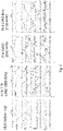
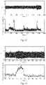
- FIG 3 shows the monitored accelerometer signals for various usages of a heart and lung machine (HLM) and LVAD.
- the accelerometer is a three axis device and in Figure 3 plot A: acceleration signal in the longitudinal direction of the heart, plot B: the circumferential direction, and plot C: the radial direction.
- the acceleration signals there are oscillations that correspond to LVAD RPM.
- the frequency distribution of the acceleration signals can be used to detect LVAD pump failure (change in higher frequencies will indicate failure).
- accelerometer signals By careful analysis of accelerometer signals it is possible to determine when there is a failure or malfunction of the pump and also to determine the type of failure. This can be done, for example, by identifying certain frequencies of motion that are associated with certain failure modes and/or by comparison of the measured signals with historical accelerometer data.
- the historical data can include accelerometer signals for pumps without failure and also accelerometer signals for pumps that malfunctioned with a known failure mechanism. It is expected that similar types of failures will produce similar irregularities in the accelerometer signals and therefore comparison with past known failures will allow future failures to be identified.
- the surgical implantation of the pump 6 and the internal part of the control wires 8 can be carried out by conventional surgical techniques.
- the implantation of the sensors 10, 12 can be done in conventional fashion.
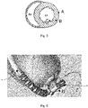
- Figures 5 and 6 Possible locations for the motion sensor(s) used for the invention are shown in Figures 5 and 6.
- Figure 5 shows a cross-section of the heart through the left ventricle (LV) and right ventricle (RV). Three general locations are shown for a motion sensor at the left ventricle, where A is an epicardial/subepicardial sensor, B is a myocardial sensor and C is an endocardial/subendocardial sensor.
- Figure 6 shows a pump 6 and graft 16 and indicates three general locations for a sensor at the pump 6 or graft 16, where D is a sensor on the pump 6, E is a sensor within the pump 6 and F is a sensor on the graft 16.
- the system could include several of the first motion sensor 10 at the right ventricle, the second motion sensor 12 at the left ventricle, the pump sensor 14 at the pump 6 and/or a sensor at the graft 16, or just one of those sensors.
- the proposed system has been tested in vitro and in vivo.
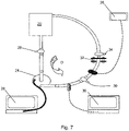
- the experimental set up used for in vitro testing of the proposed sensor system is shown in Figure 7 .
- a reservoir 20 supplied fluid to a VAD 24 of conventional type. This was equipped with an accelerometer 28 for detecting motion of the VAD 24.
- a sample port 34 was also present, for sampling of the fluid.
- a pressure regulator 32 between the VAD and reservoir was used for preload adjustment and the preload produced by this regulator was measured using a pressure sensor 30 between the VAD 24 and the regulator 32.
- a spectrum analyser 26 and Doppler sensor 36 for monitoring the circulation in the system.
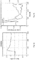
- Figure 8 is a fast Fourier transform of data from the accelerometer of Figure 7 showing detection of VAD RPM.
- the VAD RPM was changed between 1800, 2000 and 2200 as shown, and the accelerometer is able to easily detect this.
- the use of a motion sensor like an accelerometer is ideal for detecting the VAD RPM.
- the frequency data can also be used to detect a simulated thromboembolism as shown in Figure 9 .
- a third harmonic in the acceleration signal is indicative of a possible thromboembolism.
- Figures 10 and 11 illustrates changes in the acceleration signal when the afterload or preload changes.
- the afterload is increased with time and this results in an increase in the amplitude of the acceleration signal.
- the preload is decreased with time and again this results in an increase in amplitude of the acceleration signal.
- the motion sensor can hence be used to detect changes in preload or afterload. As discussed previously this can be important in detecting potential problems.
- Figure 12 shows the effects of the injection of thrombus on the acceleration signal.
- the arrows indicate the approximate time that the thrombus was injected. From left to right, the thrombi were: 0.1ml soft thrombus, solid thrombus, 0.25ml soft thrombus and 0.5ml soft thrombus. As might be expected, the larger the volume of the thrombus the greater the effect. The solid thrombus has a larger effect than the soft thrombi.
- Figure 13 shows the effects of the solid thrombus in close up view.
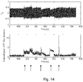
- Air embolisms were simulated in a similar fashion and Figure 14 shows the effects of the simulated air embolisms on the acceleration signal.
- the arrows indicate the approximate timing for the injection of air.
- the volume of air injected, for the arrows from left to right, was 0.1ml, 0.25ml, 0.5ml, 1ml and 2ml. It will be seen that it is possible to differentiate between air emboli, solid thrombi and soft thrombi.
- the in vivo testing used a sensor implanted in a pig.
- the pig was equipped with a LVAD with motion sensor at the LVAD for monitoring motion of the VAD.
- Figures 15 and 16 show the data from the accelerometer when viscous material was infused into the pig's left ventricle and the LVAD. The effects of this infusion on the acceleration signal can be seen and it will be understood that they are similar to the in vitro testing.
Landscapes
- Health & Medical Sciences (AREA)
- Engineering & Computer Science (AREA)
- Heart & Thoracic Surgery (AREA)
- Cardiology (AREA)
- Hematology (AREA)
- Mechanical Engineering (AREA)
- Anesthesiology (AREA)
- Biomedical Technology (AREA)
- Life Sciences & Earth Sciences (AREA)
- Animal Behavior & Ethology (AREA)
- General Health & Medical Sciences (AREA)
- Public Health (AREA)
- Veterinary Medicine (AREA)
- Medical Informatics (AREA)
- Human Computer Interaction (AREA)
- External Artificial Organs (AREA)
Applications Claiming Priority (2)
| Application Number | Priority Date | Filing Date | Title |
|---|---|---|---|
| GBGB1311494.7A GB201311494D0 (en) | 2013-06-27 | 2013-06-27 | Monitoring of a cardiac assist device |
| PCT/EP2014/063746 WO2014207225A1 (en) | 2013-06-27 | 2014-06-27 | Monitoring of a cardiac assist device |
Publications (2)
| Publication Number | Publication Date |
|---|---|
| EP3013383A1 EP3013383A1 (en) | 2016-05-04 |
| EP3013383B1 true EP3013383B1 (en) | 2022-10-12 |
Family
ID=48999097
Family Applications (1)
| Application Number | Title | Priority Date | Filing Date |
|---|---|---|---|
| EP14733214.2A Active EP3013383B1 (en) | 2013-06-27 | 2014-06-27 | Monitoring of a cardiac assist device |
Country Status (5)
| Country | Link |
|---|---|
| US (2) | US11752324B2 (es) |
| EP (1) | EP3013383B1 (es) |
| ES (1) | ES2930027T3 (es) |
| GB (1) | GB201311494D0 (es) |
| WO (1) | WO2014207225A1 (es) |
Families Citing this family (8)
| Publication number | Priority date | Publication date | Assignee | Title |
|---|---|---|---|---|
| EP3451978A4 (en) | 2016-05-06 | 2020-04-29 | University of Virginia Patent Foundation | VENTRICULAR SUPPORT DEVICE STENT, VENTRICULAR SUPPORT DEVICE, AND ASSOCIATED METHODS |
| CN105879134A (zh) * | 2016-05-16 | 2016-08-24 | 北京精密机电控制设备研究所 | 一种心室辅助装置的监控器及监控方法 |
| US10543302B2 (en) | 2017-08-16 | 2020-01-28 | Heartware, Inc. | Map measurement on VAD patients with low pulsatility |
| US10765790B2 (en) | 2018-02-20 | 2020-09-08 | Medtronic, Inc. | Detection of pump thrombosis |
| US11241570B2 (en) * | 2018-07-17 | 2022-02-08 | Tc1 Llc | Systems and methods for inertial sensing for VAD diagnostics and closed loop control |
| EP3856274B1 (en) * | 2018-09-25 | 2024-04-17 | Tc1 Llc | Adaptive speed control algorithms and controllers for optimizing flow in ventricular assist devices |
| US11590336B2 (en) * | 2019-03-05 | 2023-02-28 | Tc1 Llc | Systems and methods for evaluating blood behavior when flowing through implantable medical devices |
| CN115177860B (zh) * | 2022-09-08 | 2022-12-06 | 深圳核心医疗科技有限公司 | 性能调整方法及装置 |
Citations (3)
| Publication number | Priority date | Publication date | Assignee | Title |
|---|---|---|---|---|
| WO2005030296A2 (en) * | 2003-09-25 | 2005-04-07 | Medforte Research Foundation | Axial-flow blood pump with magnetically suspended, radially and axially stabilized impeller |
| US20060229488A1 (en) * | 2003-07-18 | 2006-10-12 | Ayre Peter J | Blood pressure detecting device and system |
| WO2014064267A1 (en) * | 2012-10-25 | 2014-05-01 | Oslo Universitetssykehus Hf | Control system for a cardiac assist device |
Family Cites Families (17)
| Publication number | Priority date | Publication date | Assignee | Title |
|---|---|---|---|---|
| GB234040A (en) | 1924-05-16 | 1925-06-18 | Bergedorfer Eisenwerk Ag | Improved apparatus for heating milk and other liquids |
| US4957504A (en) | 1988-12-02 | 1990-09-18 | Chardack William M | Implantable blood pump |
| NL9001953A (nl) | 1990-09-05 | 1992-04-01 | Frits Frans Maria De Mul P A U | Optische bloed-debietmeter voor kunsthartsystemen. |
| US6176822B1 (en) * | 1998-03-31 | 2001-01-23 | Impella Cardiotechnik Gmbh | Intracardiac blood pump |
| US6254525B1 (en) | 1998-11-04 | 2001-07-03 | Cardio Technologies, Inc. | Cardiac assist system and method thereof |
| NO20016385L (no) | 2001-12-27 | 2003-06-30 | Medinnova Sf | System for å overvåke pulsendringer, fortrinnsvis en hjertemuskel |
| AU2002951685A0 (en) | 2002-09-30 | 2002-10-17 | Ventrassist Pty Ltd | Physiological demand responsive control system |
| US7572217B1 (en) | 2004-06-15 | 2009-08-11 | University Of Louisville Research Foundation, Inc. | System and method for providing cardiac support and promoting myocardial recovery |
| US7513864B2 (en) | 2004-07-09 | 2009-04-07 | Kantrowitz Allen B | Synchronization system between aortic valve and cardiac assist device |
| EP2180834B1 (en) | 2007-08-30 | 2011-05-04 | Oslo Universitetssykehus HF | Automated monitoring of myocardial function by ultrasonic transducers positioned on the heart |
| JP5250866B2 (ja) | 2008-06-11 | 2013-07-31 | 株式会社サンメディカル技術研究所 | 人工心臓制御装置及び人工心臓システム |
| JP5810459B2 (ja) | 2010-12-03 | 2015-11-11 | 株式会社サンメディカル技術研究所 | 人工心臓装置 |
| WO2012112378A2 (en) | 2011-02-18 | 2012-08-23 | Vascor Inc. | Blood flow assist systems |
| WO2013003370A2 (en) | 2011-06-27 | 2013-01-03 | Heartware, Inc. | Flow estimation in a blood pump |
| WO2014015300A1 (en) * | 2012-07-19 | 2014-01-23 | Regents Of The University Of Minnesota | Cardiac assist device with pulse wave analysis |
| WO2014062827A1 (en) * | 2012-10-16 | 2014-04-24 | Spence Paul A | Devices, systems, and methods for facilitating flow from the heart to a blood pump |
| US12070601B2 (en) * | 2014-03-28 | 2024-08-27 | Pinnacle Bionics. Inc. | Stimulation system for exercising diaphragm and method of operation thereof |
-
2013
- 2013-06-27 GB GBGB1311494.7A patent/GB201311494D0/en not_active Ceased
-
2014
- 2014-06-27 EP EP14733214.2A patent/EP3013383B1/en active Active
- 2014-06-27 ES ES14733214T patent/ES2930027T3/es active Active
- 2014-06-27 US US14/901,023 patent/US11752324B2/en active Active
- 2014-06-27 WO PCT/EP2014/063746 patent/WO2014207225A1/en active Application Filing
-
2023
- 2023-09-06 US US18/462,135 patent/US20230405304A1/en active Pending
Patent Citations (3)
| Publication number | Priority date | Publication date | Assignee | Title |
|---|---|---|---|---|
| US20060229488A1 (en) * | 2003-07-18 | 2006-10-12 | Ayre Peter J | Blood pressure detecting device and system |
| WO2005030296A2 (en) * | 2003-09-25 | 2005-04-07 | Medforte Research Foundation | Axial-flow blood pump with magnetically suspended, radially and axially stabilized impeller |
| WO2014064267A1 (en) * | 2012-10-25 | 2014-05-01 | Oslo Universitetssykehus Hf | Control system for a cardiac assist device |
Also Published As
| Publication number | Publication date |
|---|---|
| ES2930027T3 (es) | 2022-12-05 |
| US11752324B2 (en) | 2023-09-12 |
| GB201311494D0 (en) | 2013-08-14 |
| EP3013383A1 (en) | 2016-05-04 |
| US20170049945A1 (en) | 2017-02-23 |
| WO2014207225A1 (en) | 2014-12-31 |
| US20230405304A1 (en) | 2023-12-21 |
Similar Documents
| Publication | Publication Date | Title |
|---|---|---|
| US20230405304A1 (en) | Monitoring of a cardiac assist device | |
| US11779234B2 (en) | Pressure sensing ventricular assist devices and methods of use | |
| CN110913923B (zh) | 用于调节血液泵支持的对心脏参数的确定 | |
| ES2874203T3 (es) | Sistema de asistencia cardiovascular que cuantifica la función cardíaca y facilita la recuperación cardíaca | |
| JP5898190B2 (ja) | 流体送達システム及び流体送達システムを監視するための方法 | |
| US7284956B2 (en) | Methods and apparatus for controlling a continuous flow rotary blood pump | |
| CN104822400B (zh) | 控制心室辅助设备(vad)的速度的方法和心室辅助设备 | |
| JP6616405B2 (ja) | 心室補助人工心臓の方法及び装置 | |
| JP2020531122A (ja) | 血液ポンプ | |
| JP2008500864A (ja) | 心臓機能評価システム | |
| US20150322940A1 (en) | Artificial heart system implementing suction recognition and avoidance methods | |
| JP2011515174A (ja) | 心臓補助装置 | |
| JP2003047656A (ja) | 心室補助装置及び心室補助方法 | |
| US20190358383A1 (en) | Heart rate determination based on vad current waveform | |
| CN116236685B (zh) | 电机转速的控制方法及装置 | |
| WO2014064267A1 (en) | Control system for a cardiac assist device | |
| EP3139974B1 (en) | Artificial heart system implementing suction recognition and avoidance | |
| US20150080748A1 (en) | Method and System for Predicting Cardiovascular Events | |
| JP2022552889A (ja) | コントローラ及び複数のセンサを含む循環サポートシステム及びその操作方法 | |
| JP2005066013A (ja) | 定常流ロータリ血液ポンプ制御のための方法及び装置 | |
| JP7308853B2 (ja) | 機器および方法 | |
| Schalit | Accelerometer-based monitoring of left ventricular assist device: tromboembolism and pump thrombosis detection in HeartWare HVAD | |
| WO2024123987A1 (en) | Estimating contractile reserve using a mechnical circulatory support device | |
| Adnadjevic | Development of a suction detection system for a motorized pulsatile blood pump | |
| Gopalakrishnan et al. | Evaluation of a minimally invasive cardiac function estimator for patients with rotary VAD support |
Legal Events
| Date | Code | Title | Description |
|---|---|---|---|
| PUAI | Public reference made under article 153(3) epc to a published international application that has entered the european phase |
Free format text: ORIGINAL CODE: 0009012 |
|
| STAA | Information on the status of an ep patent application or granted ep patent |
Free format text: STATUS: REQUEST FOR EXAMINATION WAS MADE |
|
| 17P | Request for examination filed |
Effective date: 20160113 |
|
| AK | Designated contracting states |
Kind code of ref document: A1 Designated state(s): AL AT BE BG CH CY CZ DE DK EE ES FI FR GB GR HR HU IE IS IT LI LT LU LV MC MK MT NL NO PL PT RO RS SE SI SK SM TR |
|
| AX | Request for extension of the european patent |
Extension state: BA ME |
|
| DAX | Request for extension of the european patent (deleted) | ||
| STAA | Information on the status of an ep patent application or granted ep patent |
Free format text: STATUS: EXAMINATION IS IN PROGRESS |
|
| 17Q | First examination report despatched |
Effective date: 20210519 |
|
| STAA | Information on the status of an ep patent application or granted ep patent |
Free format text: STATUS: EXAMINATION IS IN PROGRESS |
|
| RAP1 | Party data changed (applicant data changed or rights of an application transferred) |
Owner name: CARDIACCS AS |
|
| REG | Reference to a national code |
Ref country code: DE Ref legal event code: R079 Ref document number: 602014085200 Country of ref document: DE Free format text: PREVIOUS MAIN CLASS: A61M0001100000 Ipc: A61M0060122000 |
|
| GRAP | Despatch of communication of intention to grant a patent |
Free format text: ORIGINAL CODE: EPIDOSNIGR1 |
|
| STAA | Information on the status of an ep patent application or granted ep patent |
Free format text: STATUS: GRANT OF PATENT IS INTENDED |
|
| RIC1 | Information provided on ipc code assigned before grant |
Ipc: A61M 60/205 20210101ALI20220323BHEP Ipc: A61M 60/148 20210101ALI20220323BHEP Ipc: A61M 60/122 20210101AFI20220323BHEP |
|
| INTG | Intention to grant announced |
Effective date: 20220422 |
|
| GRAS | Grant fee paid |
Free format text: ORIGINAL CODE: EPIDOSNIGR3 |
|
| GRAA | (expected) grant |
Free format text: ORIGINAL CODE: 0009210 |
|
| STAA | Information on the status of an ep patent application or granted ep patent |
Free format text: STATUS: THE PATENT HAS BEEN GRANTED |
|
| AK | Designated contracting states |
Kind code of ref document: B1 Designated state(s): AL AT BE BG CH CY CZ DE DK EE ES FI FR GB GR HR HU IE IS IT LI LT LU LV MC MK MT NL NO PL PT RO RS SE SI SK SM TR |
|
| REG | Reference to a national code |
Ref country code: GB Ref legal event code: FG4D |
|
| REG | Reference to a national code |
Ref country code: CH Ref legal event code: EP |
|
| REG | Reference to a national code |
Ref country code: DE Ref legal event code: R096 Ref document number: 602014085200 Country of ref document: DE |
|
| REG | Reference to a national code |
Ref country code: IE Ref legal event code: FG4D |
|
| REG | Reference to a national code |
Ref country code: AT Ref legal event code: REF Ref document number: 1523791 Country of ref document: AT Kind code of ref document: T Effective date: 20221115 |
|
| REG | Reference to a national code |
Ref country code: ES Ref legal event code: FG2A Ref document number: 2930027 Country of ref document: ES Kind code of ref document: T3 Effective date: 20221205 |
|
| REG | Reference to a national code |
Ref country code: SE Ref legal event code: TRGR |
|
| REG | Reference to a national code |
Ref country code: LT Ref legal event code: MG9D |
|
| REG | Reference to a national code |
Ref country code: NL Ref legal event code: MP Effective date: 20221012 |
|
| REG | Reference to a national code |
Ref country code: AT Ref legal event code: MK05 Ref document number: 1523791 Country of ref document: AT Kind code of ref document: T Effective date: 20221012 |
|
| PG25 | Lapsed in a contracting state [announced via postgrant information from national office to epo] |
Ref country code: NL Free format text: LAPSE BECAUSE OF FAILURE TO SUBMIT A TRANSLATION OF THE DESCRIPTION OR TO PAY THE FEE WITHIN THE PRESCRIBED TIME-LIMIT Effective date: 20221012 |
|
| PG25 | Lapsed in a contracting state [announced via postgrant information from national office to epo] |
Ref country code: PT Free format text: LAPSE BECAUSE OF FAILURE TO SUBMIT A TRANSLATION OF THE DESCRIPTION OR TO PAY THE FEE WITHIN THE PRESCRIBED TIME-LIMIT Effective date: 20230213 Ref country code: NO Free format text: LAPSE BECAUSE OF FAILURE TO SUBMIT A TRANSLATION OF THE DESCRIPTION OR TO PAY THE FEE WITHIN THE PRESCRIBED TIME-LIMIT Effective date: 20230112 Ref country code: LT Free format text: LAPSE BECAUSE OF FAILURE TO SUBMIT A TRANSLATION OF THE DESCRIPTION OR TO PAY THE FEE WITHIN THE PRESCRIBED TIME-LIMIT Effective date: 20221012 Ref country code: FI Free format text: LAPSE BECAUSE OF FAILURE TO SUBMIT A TRANSLATION OF THE DESCRIPTION OR TO PAY THE FEE WITHIN THE PRESCRIBED TIME-LIMIT Effective date: 20221012 Ref country code: AT Free format text: LAPSE BECAUSE OF FAILURE TO SUBMIT A TRANSLATION OF THE DESCRIPTION OR TO PAY THE FEE WITHIN THE PRESCRIBED TIME-LIMIT Effective date: 20221012 |
|
| PG25 | Lapsed in a contracting state [announced via postgrant information from national office to epo] |
Ref country code: RS Free format text: LAPSE BECAUSE OF FAILURE TO SUBMIT A TRANSLATION OF THE DESCRIPTION OR TO PAY THE FEE WITHIN THE PRESCRIBED TIME-LIMIT Effective date: 20221012 Ref country code: PL Free format text: LAPSE BECAUSE OF FAILURE TO SUBMIT A TRANSLATION OF THE DESCRIPTION OR TO PAY THE FEE WITHIN THE PRESCRIBED TIME-LIMIT Effective date: 20221012 Ref country code: LV Free format text: LAPSE BECAUSE OF FAILURE TO SUBMIT A TRANSLATION OF THE DESCRIPTION OR TO PAY THE FEE WITHIN THE PRESCRIBED TIME-LIMIT Effective date: 20221012 Ref country code: IS Free format text: LAPSE BECAUSE OF FAILURE TO SUBMIT A TRANSLATION OF THE DESCRIPTION OR TO PAY THE FEE WITHIN THE PRESCRIBED TIME-LIMIT Effective date: 20230212 Ref country code: HR Free format text: LAPSE BECAUSE OF FAILURE TO SUBMIT A TRANSLATION OF THE DESCRIPTION OR TO PAY THE FEE WITHIN THE PRESCRIBED TIME-LIMIT Effective date: 20221012 Ref country code: GR Free format text: LAPSE BECAUSE OF FAILURE TO SUBMIT A TRANSLATION OF THE DESCRIPTION OR TO PAY THE FEE WITHIN THE PRESCRIBED TIME-LIMIT Effective date: 20230113 |
|
| P01 | Opt-out of the competence of the unified patent court (upc) registered |
Effective date: 20230515 |
|
| REG | Reference to a national code |
Ref country code: DE Ref legal event code: R097 Ref document number: 602014085200 Country of ref document: DE |
|
| PG25 | Lapsed in a contracting state [announced via postgrant information from national office to epo] |
Ref country code: SM Free format text: LAPSE BECAUSE OF FAILURE TO SUBMIT A TRANSLATION OF THE DESCRIPTION OR TO PAY THE FEE WITHIN THE PRESCRIBED TIME-LIMIT Effective date: 20221012 Ref country code: RO Free format text: LAPSE BECAUSE OF FAILURE TO SUBMIT A TRANSLATION OF THE DESCRIPTION OR TO PAY THE FEE WITHIN THE PRESCRIBED TIME-LIMIT Effective date: 20221012 Ref country code: EE Free format text: LAPSE BECAUSE OF FAILURE TO SUBMIT A TRANSLATION OF THE DESCRIPTION OR TO PAY THE FEE WITHIN THE PRESCRIBED TIME-LIMIT Effective date: 20221012 Ref country code: DK Free format text: LAPSE BECAUSE OF FAILURE TO SUBMIT A TRANSLATION OF THE DESCRIPTION OR TO PAY THE FEE WITHIN THE PRESCRIBED TIME-LIMIT Effective date: 20221012 Ref country code: CZ Free format text: LAPSE BECAUSE OF FAILURE TO SUBMIT A TRANSLATION OF THE DESCRIPTION OR TO PAY THE FEE WITHIN THE PRESCRIBED TIME-LIMIT Effective date: 20221012 |
|
| PGFP | Annual fee paid to national office [announced via postgrant information from national office to epo] |
Ref country code: DE Payment date: 20230621 Year of fee payment: 10 |
|
| PLBE | No opposition filed within time limit |
Free format text: ORIGINAL CODE: 0009261 |
|
| STAA | Information on the status of an ep patent application or granted ep patent |
Free format text: STATUS: NO OPPOSITION FILED WITHIN TIME LIMIT |
|
| PG25 | Lapsed in a contracting state [announced via postgrant information from national office to epo] |
Ref country code: SK Free format text: LAPSE BECAUSE OF FAILURE TO SUBMIT A TRANSLATION OF THE DESCRIPTION OR TO PAY THE FEE WITHIN THE PRESCRIBED TIME-LIMIT Effective date: 20221012 Ref country code: AL Free format text: LAPSE BECAUSE OF FAILURE TO SUBMIT A TRANSLATION OF THE DESCRIPTION OR TO PAY THE FEE WITHIN THE PRESCRIBED TIME-LIMIT Effective date: 20221012 |
|
| 26N | No opposition filed |
Effective date: 20230713 |
|
| PGFP | Annual fee paid to national office [announced via postgrant information from national office to epo] |
Ref country code: ES Payment date: 20230703 Year of fee payment: 10 Ref country code: CH Payment date: 20230702 Year of fee payment: 10 |
|
| PG25 | Lapsed in a contracting state [announced via postgrant information from national office to epo] |
Ref country code: SI Free format text: LAPSE BECAUSE OF FAILURE TO SUBMIT A TRANSLATION OF THE DESCRIPTION OR TO PAY THE FEE WITHIN THE PRESCRIBED TIME-LIMIT Effective date: 20221012 |
|
| PG25 | Lapsed in a contracting state [announced via postgrant information from national office to epo] |
Ref country code: MC Free format text: LAPSE BECAUSE OF FAILURE TO SUBMIT A TRANSLATION OF THE DESCRIPTION OR TO PAY THE FEE WITHIN THE PRESCRIBED TIME-LIMIT Effective date: 20221012 |
|
| PG25 | Lapsed in a contracting state [announced via postgrant information from national office to epo] |
Ref country code: MC Free format text: LAPSE BECAUSE OF FAILURE TO SUBMIT A TRANSLATION OF THE DESCRIPTION OR TO PAY THE FEE WITHIN THE PRESCRIBED TIME-LIMIT Effective date: 20221012 |
|
| REG | Reference to a national code |
Ref country code: BE Ref legal event code: MM Effective date: 20230630 |
|
| PG25 | Lapsed in a contracting state [announced via postgrant information from national office to epo] |
Ref country code: LU Free format text: LAPSE BECAUSE OF NON-PAYMENT OF DUE FEES Effective date: 20230627 |
|
| REG | Reference to a national code |
Ref country code: IE Ref legal event code: MM4A |
|
| PG25 | Lapsed in a contracting state [announced via postgrant information from national office to epo] |
Ref country code: LU Free format text: LAPSE BECAUSE OF NON-PAYMENT OF DUE FEES Effective date: 20230627 |
|
| PG25 | Lapsed in a contracting state [announced via postgrant information from national office to epo] |
Ref country code: IE Free format text: LAPSE BECAUSE OF NON-PAYMENT OF DUE FEES Effective date: 20230627 |
|
| PG25 | Lapsed in a contracting state [announced via postgrant information from national office to epo] |
Ref country code: IE Free format text: LAPSE BECAUSE OF NON-PAYMENT OF DUE FEES Effective date: 20230627 |
|
| PG25 | Lapsed in a contracting state [announced via postgrant information from national office to epo] |
Ref country code: IT Free format text: LAPSE BECAUSE OF FAILURE TO SUBMIT A TRANSLATION OF THE DESCRIPTION OR TO PAY THE FEE WITHIN THE PRESCRIBED TIME-LIMIT Effective date: 20221012 Ref country code: FR Free format text: LAPSE BECAUSE OF NON-PAYMENT OF DUE FEES Effective date: 20230630 Ref country code: BE Free format text: LAPSE BECAUSE OF NON-PAYMENT OF DUE FEES Effective date: 20230630 |
|
| PGFP | Annual fee paid to national office [announced via postgrant information from national office to epo] |
Ref country code: GB Payment date: 20240619 Year of fee payment: 11 |
|
| PGFP | Annual fee paid to national office [announced via postgrant information from national office to epo] |
Ref country code: SE Payment date: 20240620 Year of fee payment: 11 |