EP3011918B1 - Têtes de coupe sans danger et systèmes permettant de retirer rapidement un tissu cible - Google Patents
Têtes de coupe sans danger et systèmes permettant de retirer rapidement un tissu cible Download PDFInfo
- Publication number
- EP3011918B1 EP3011918B1 EP15189482.1A EP15189482A EP3011918B1 EP 3011918 B1 EP3011918 B1 EP 3011918B1 EP 15189482 A EP15189482 A EP 15189482A EP 3011918 B1 EP3011918 B1 EP 3011918B1
- Authority
- EP
- European Patent Office
- Prior art keywords
- cutting head
- cutting
- tissue
- lumen
- suction
- Prior art date
- Legal status (The legal status is an assumption and is not a legal conclusion. Google has not performed a legal analysis and makes no representation as to the accuracy of the status listed.)
- Active
Links
- 230000002262 irrigation Effects 0.000 claims description 36
- 238000003973 irrigation Methods 0.000 claims description 36
- 238000004891 communication Methods 0.000 claims description 27
- 239000012530 fluid Substances 0.000 claims description 19
- 230000001419 dependent effect Effects 0.000 claims description 5
- 210000001519 tissue Anatomy 0.000 description 174
- 238000000034 method Methods 0.000 description 30
- 238000013461 design Methods 0.000 description 24
- 210000000988 bone and bone Anatomy 0.000 description 13
- 210000000845 cartilage Anatomy 0.000 description 10
- 230000004927 fusion Effects 0.000 description 10
- 238000001356 surgical procedure Methods 0.000 description 9
- 206010016654 Fibrosis Diseases 0.000 description 7
- 230000001154 acute effect Effects 0.000 description 7
- 230000004761 fibrosis Effects 0.000 description 7
- 239000000463 material Substances 0.000 description 7
- 210000004204 blood vessel Anatomy 0.000 description 6
- 210000000981 epithelium Anatomy 0.000 description 6
- 210000003205 muscle Anatomy 0.000 description 6
- 229910001220 stainless steel Inorganic materials 0.000 description 6
- 230000009471 action Effects 0.000 description 5
- 239000010935 stainless steel Substances 0.000 description 5
- 238000013459 approach Methods 0.000 description 4
- 210000000080 chela (arthropods) Anatomy 0.000 description 4
- 239000007789 gas Substances 0.000 description 4
- 239000003621 irrigation water Substances 0.000 description 4
- 230000005499 meniscus Effects 0.000 description 4
- 241000283984 Rodentia Species 0.000 description 3
- 239000007788 liquid Substances 0.000 description 3
- 230000032258 transport Effects 0.000 description 3
- XLYOFNOQVPJJNP-UHFFFAOYSA-N water Substances O XLYOFNOQVPJJNP-UHFFFAOYSA-N 0.000 description 3
- IJGRMHOSHXDMSA-UHFFFAOYSA-N Atomic nitrogen Chemical compound N#N IJGRMHOSHXDMSA-UHFFFAOYSA-N 0.000 description 2
- 208000008035 Back Pain Diseases 0.000 description 2
- CURLTUGMZLYLDI-UHFFFAOYSA-N Carbon dioxide Chemical compound O=C=O CURLTUGMZLYLDI-UHFFFAOYSA-N 0.000 description 2
- PEDCQBHIVMGVHV-UHFFFAOYSA-N Glycerine Chemical compound OCC(O)CO PEDCQBHIVMGVHV-UHFFFAOYSA-N 0.000 description 2
- 241001465754 Metazoa Species 0.000 description 2
- 239000004696 Poly ether ether ketone Substances 0.000 description 2
- 241000288906 Primates Species 0.000 description 2
- WYTGDNHDOZPMIW-RCBQFDQVSA-N alstonine Natural products C1=CC2=C3C=CC=CC3=NC2=C2N1C[C@H]1[C@H](C)OC=C(C(=O)OC)[C@H]1C2 WYTGDNHDOZPMIW-RCBQFDQVSA-N 0.000 description 2
- 239000000919 ceramic Substances 0.000 description 2
- 239000011248 coating agent Substances 0.000 description 2
- 238000000576 coating method Methods 0.000 description 2
- 238000002594 fluoroscopy Methods 0.000 description 2
- 238000003384 imaging method Methods 0.000 description 2
- 210000005067 joint tissue Anatomy 0.000 description 2
- 230000010534 mechanism of action Effects 0.000 description 2
- 229920002530 polyetherether ketone Polymers 0.000 description 2
- 230000008569 process Effects 0.000 description 2
- 210000002435 tendon Anatomy 0.000 description 2
- 238000012360 testing method Methods 0.000 description 2
- 230000036346 tooth eruption Effects 0.000 description 2
- 239000010963 304 stainless steel Substances 0.000 description 1
- 229910000619 316 stainless steel Inorganic materials 0.000 description 1
- 241000283690 Bos taurus Species 0.000 description 1
- 229920000049 Carbon (fiber) Polymers 0.000 description 1
- 241000282693 Cercopithecidae Species 0.000 description 1
- 229910000684 Cobalt-chrome Inorganic materials 0.000 description 1
- 102000008186 Collagen Human genes 0.000 description 1
- 108010035532 Collagen Proteins 0.000 description 1
- 241000283073 Equus caballus Species 0.000 description 1
- 241000282326 Felis catus Species 0.000 description 1
- 229910000677 High-carbon steel Inorganic materials 0.000 description 1
- 206010061246 Intervertebral disc degeneration Diseases 0.000 description 1
- 208000018650 Intervertebral disc disease Diseases 0.000 description 1
- 208000008930 Low Back Pain Diseases 0.000 description 1
- 241000124008 Mammalia Species 0.000 description 1
- 241000699666 Mus <mouse, genus> Species 0.000 description 1
- 206010029174 Nerve compression Diseases 0.000 description 1
- 241000009328 Perro Species 0.000 description 1
- 239000002202 Polyethylene glycol Substances 0.000 description 1
- 239000004642 Polyimide Substances 0.000 description 1
- 239000004372 Polyvinyl alcohol Substances 0.000 description 1
- 241000700159 Rattus Species 0.000 description 1
- 229910000589 SAE 304 stainless steel Inorganic materials 0.000 description 1
- XUIMIQQOPSSXEZ-UHFFFAOYSA-N Silicon Chemical compound [Si] XUIMIQQOPSSXEZ-UHFFFAOYSA-N 0.000 description 1
- FAPWRFPIFSIZLT-UHFFFAOYSA-M Sodium chloride Chemical compound [Na+].[Cl-] FAPWRFPIFSIZLT-UHFFFAOYSA-M 0.000 description 1
- 229910000831 Steel Inorganic materials 0.000 description 1
- 241000282898 Sus scrofa Species 0.000 description 1
- 239000004809 Teflon Substances 0.000 description 1
- 229920006362 Teflon® Polymers 0.000 description 1
- 229910001069 Ti alloy Inorganic materials 0.000 description 1
- RTAQQCXQSZGOHL-UHFFFAOYSA-N Titanium Chemical compound [Ti] RTAQQCXQSZGOHL-UHFFFAOYSA-N 0.000 description 1
- WAIPAZQMEIHHTJ-UHFFFAOYSA-N [Cr].[Co] Chemical compound [Cr].[Co] WAIPAZQMEIHHTJ-UHFFFAOYSA-N 0.000 description 1
- 239000003570 air Substances 0.000 description 1
- 238000005452 bending Methods 0.000 description 1
- 238000001574 biopsy Methods 0.000 description 1
- 229910002092 carbon dioxide Inorganic materials 0.000 description 1
- 239000001569 carbon dioxide Substances 0.000 description 1
- 239000004917 carbon fiber Substances 0.000 description 1
- 239000010952 cobalt-chrome Substances 0.000 description 1
- 229920001436 collagen Polymers 0.000 description 1
- 230000001010 compromised effect Effects 0.000 description 1
- 238000010276 construction Methods 0.000 description 1
- 230000003247 decreasing effect Effects 0.000 description 1
- 230000007850 degeneration Effects 0.000 description 1
- 230000032798 delamination Effects 0.000 description 1
- 239000010432 diamond Substances 0.000 description 1
- 229910003460 diamond Inorganic materials 0.000 description 1
- 230000003292 diminished effect Effects 0.000 description 1
- 238000002224 dissection Methods 0.000 description 1
- 230000000694 effects Effects 0.000 description 1
- 210000004177 elastic tissue Anatomy 0.000 description 1
- 239000000839 emulsion Substances 0.000 description 1
- 238000000605 extraction Methods 0.000 description 1
- 235000011187 glycerol Nutrition 0.000 description 1
- 238000000227 grinding Methods 0.000 description 1
- 230000005802 health problem Effects 0.000 description 1
- 230000002209 hydrophobic effect Effects 0.000 description 1
- 238000003780 insertion Methods 0.000 description 1
- 230000037431 insertion Effects 0.000 description 1
- 208000021600 intervertebral disc degenerative disease Diseases 0.000 description 1
- 244000144972 livestock Species 0.000 description 1
- 238000011068 loading method Methods 0.000 description 1
- 239000000314 lubricant Substances 0.000 description 1
- 229910052751 metal Inorganic materials 0.000 description 1
- 239000002184 metal Substances 0.000 description 1
- VNWKTOKETHGBQD-UHFFFAOYSA-N methane Chemical compound C VNWKTOKETHGBQD-UHFFFAOYSA-N 0.000 description 1
- 210000005036 nerve Anatomy 0.000 description 1
- 229910052757 nitrogen Inorganic materials 0.000 description 1
- 239000005332 obsidian Substances 0.000 description 1
- 239000003921 oil Substances 0.000 description 1
- 230000000399 orthopedic effect Effects 0.000 description 1
- 230000000704 physical effect Effects 0.000 description 1
- 239000004033 plastic Substances 0.000 description 1
- 229920003023 plastic Polymers 0.000 description 1
- 229920000052 poly(p-xylylene) Polymers 0.000 description 1
- 229920001223 polyethylene glycol Polymers 0.000 description 1
- 229920001721 polyimide Polymers 0.000 description 1
- 229920000642 polymer Polymers 0.000 description 1
- 229920002451 polyvinyl alcohol Polymers 0.000 description 1
- 230000001737 promoting effect Effects 0.000 description 1
- 230000009467 reduction Effects 0.000 description 1
- 239000011347 resin Substances 0.000 description 1
- 229920005989 resin Polymers 0.000 description 1
- 238000007790 scraping Methods 0.000 description 1
- 229910052710 silicon Inorganic materials 0.000 description 1
- 239000010703 silicon Substances 0.000 description 1
- 239000011780 sodium chloride Substances 0.000 description 1
- 210000004872 soft tissue Anatomy 0.000 description 1
- 230000006641 stabilisation Effects 0.000 description 1
- 238000011105 stabilization Methods 0.000 description 1
- 239000010959 steel Substances 0.000 description 1
- 239000004094 surface-active agent Substances 0.000 description 1
- 229910000811 surgical stainless steel Inorganic materials 0.000 description 1
- 238000010408 sweeping Methods 0.000 description 1
- 208000024891 symptom Diseases 0.000 description 1
- BFKJFAAPBSQJPD-UHFFFAOYSA-N tetrafluoroethene Chemical compound FC(F)=C(F)F BFKJFAAPBSQJPD-UHFFFAOYSA-N 0.000 description 1
- 229910052719 titanium Inorganic materials 0.000 description 1
- 239000010936 titanium Substances 0.000 description 1
- 230000000472 traumatic effect Effects 0.000 description 1
- UONOETXJSWQNOL-UHFFFAOYSA-N tungsten carbide Chemical compound [W+]#[C-] UONOETXJSWQNOL-UHFFFAOYSA-N 0.000 description 1
- 210000002517 zygapophyseal joint Anatomy 0.000 description 1
Images


Classifications
-
- A—HUMAN NECESSITIES
- A61—MEDICAL OR VETERINARY SCIENCE; HYGIENE
- A61B—DIAGNOSIS; SURGERY; IDENTIFICATION
- A61B17/00—Surgical instruments, devices or methods, e.g. tourniquets
- A61B17/32—Surgical cutting instruments
- A61B17/3205—Excision instruments
-
- A—HUMAN NECESSITIES
- A61—MEDICAL OR VETERINARY SCIENCE; HYGIENE
- A61B—DIAGNOSIS; SURGERY; IDENTIFICATION
- A61B17/00—Surgical instruments, devices or methods, e.g. tourniquets
- A61B17/32—Surgical cutting instruments
- A61B17/320016—Endoscopic cutting instruments, e.g. arthroscopes, resectoscopes
- A61B17/32002—Endoscopic cutting instruments, e.g. arthroscopes, resectoscopes with continuously rotating, oscillating or reciprocating cutting instruments
-
- A—HUMAN NECESSITIES
- A61—MEDICAL OR VETERINARY SCIENCE; HYGIENE
- A61F—FILTERS IMPLANTABLE INTO BLOOD VESSELS; PROSTHESES; DEVICES PROVIDING PATENCY TO, OR PREVENTING COLLAPSING OF, TUBULAR STRUCTURES OF THE BODY, e.g. STENTS; ORTHOPAEDIC, NURSING OR CONTRACEPTIVE DEVICES; FOMENTATION; TREATMENT OR PROTECTION OF EYES OR EARS; BANDAGES, DRESSINGS OR ABSORBENT PADS; FIRST-AID KITS
- A61F2/00—Filters implantable into blood vessels; Prostheses, i.e. artificial substitutes or replacements for parts of the body; Appliances for connecting them with the body; Devices providing patency to, or preventing collapsing of, tubular structures of the body, e.g. stents
- A61F2/02—Prostheses implantable into the body
- A61F2/30—Joints
- A61F2/44—Joints for the spine, e.g. vertebrae, spinal discs
-
- A—HUMAN NECESSITIES
- A61—MEDICAL OR VETERINARY SCIENCE; HYGIENE
- A61B—DIAGNOSIS; SURGERY; IDENTIFICATION
- A61B17/00—Surgical instruments, devices or methods, e.g. tourniquets
- A61B17/00234—Surgical instruments, devices or methods, e.g. tourniquets for minimally invasive surgery
- A61B2017/00238—Type of minimally invasive operation
- A61B2017/00261—Discectomy
-
- A—HUMAN NECESSITIES
- A61—MEDICAL OR VETERINARY SCIENCE; HYGIENE
- A61B—DIAGNOSIS; SURGERY; IDENTIFICATION
- A61B17/00—Surgical instruments, devices or methods, e.g. tourniquets
- A61B2017/00681—Aspects not otherwise provided for
- A61B2017/00738—Aspects not otherwise provided for part of the tool being offset with respect to a main axis, e.g. for better view for the surgeon
-
- A—HUMAN NECESSITIES
- A61—MEDICAL OR VETERINARY SCIENCE; HYGIENE
- A61B—DIAGNOSIS; SURGERY; IDENTIFICATION
- A61B17/00—Surgical instruments, devices or methods, e.g. tourniquets
- A61B17/32—Surgical cutting instruments
- A61B2017/320064—Surgical cutting instruments with tissue or sample retaining means
-
- A—HUMAN NECESSITIES
- A61—MEDICAL OR VETERINARY SCIENCE; HYGIENE
- A61B—DIAGNOSIS; SURGERY; IDENTIFICATION
- A61B90/00—Instruments, implements or accessories specially adapted for surgery or diagnosis and not covered by any of the groups A61B1/00 - A61B50/00, e.g. for luxation treatment or for protecting wound edges
- A61B90/08—Accessories or related features not otherwise provided for
- A61B2090/0801—Prevention of accidental cutting or pricking
- A61B2090/08021—Prevention of accidental cutting or pricking of the patient or his organs
-
- A—HUMAN NECESSITIES
- A61—MEDICAL OR VETERINARY SCIENCE; HYGIENE
- A61B—DIAGNOSIS; SURGERY; IDENTIFICATION
- A61B2217/00—General characteristics of surgical instruments
- A61B2217/002—Auxiliary appliance
-
- A—HUMAN NECESSITIES
- A61—MEDICAL OR VETERINARY SCIENCE; HYGIENE
- A61F—FILTERS IMPLANTABLE INTO BLOOD VESSELS; PROSTHESES; DEVICES PROVIDING PATENCY TO, OR PREVENTING COLLAPSING OF, TUBULAR STRUCTURES OF THE BODY, e.g. STENTS; ORTHOPAEDIC, NURSING OR CONTRACEPTIVE DEVICES; FOMENTATION; TREATMENT OR PROTECTION OF EYES OR EARS; BANDAGES, DRESSINGS OR ABSORBENT PADS; FIRST-AID KITS
- A61F2/00—Filters implantable into blood vessels; Prostheses, i.e. artificial substitutes or replacements for parts of the body; Appliances for connecting them with the body; Devices providing patency to, or preventing collapsing of, tubular structures of the body, e.g. stents
- A61F2/02—Prostheses implantable into the body
- A61F2/30—Joints
- A61F2/44—Joints for the spine, e.g. vertebrae, spinal discs
- A61F2/442—Intervertebral or spinal discs, e.g. resilient
- A61F2002/444—Intervertebral or spinal discs, e.g. resilient for replacing the nucleus pulposus
Definitions
- the teachings provided herein are generally directed to a safe and efficient cutting head for removing a target tissue from a subject during a surgical procedure.
- Intervertebral disc disease is a major worldwide health problem. In the United States alone almost 700,000 spine procedures are performed each year and the total cost of treatment of back pain exceeds $30 billion. Age related changes in the disc include diminished water content in the nucleus and increased collagen content by the 4.sup.th decade of life. Loss of water binding by the nucleus results in more compressive loading of the annulus. This renders the annulus more susceptible to delamination and damage. Damage to the annulus, in turn, accelerates disc degeneration and degeneration of surrounding tissues such as the facet joints.
- the two most common spinal surgical procedures performed are discectomy and spinal fusion. These procedures only address the symptom of lower back pain, nerve compression, instability and deformity.
- the objective of the spinal disc fusion procedure is to restore, maintain and stabilize disc height, and/or reduce back pain.
- the procedure is generally performed by removing central disc material such and inner annulus, nucleus pulposus and the cartilage on the endplates before replacing with bone graft and a scaffold to effect fusion of the vertebral bodies within the treated disc for height stabilization. This removal process is called a discectomy and is both tedious and frequently inadequate which can result in compromised fusion, as well as traumatic and time consuming due to the large incision and dissections required to expose the disc for discectomy.
- a nucleotomy is first performed in which the nucleus is loosened by using a curette or a manual shaver to shear the nucleus loose and then removed using a rigid grasper called a rongeur.
- the surgeon has to insert the rongeur through an opening in the disc called an anulotomy, grasp nucleus and remove out of the disc and the surgical access, clean the jaws and reinsert for more grasping of disc repeatedly.
- This process can pose safety issues for tissues in between tool passage such as nerves.
- disc debris left behind can hinder efficient subsequent tissue removal and insertion of the discectomy tools into the disc.
- the second step is decortication in which cartilage attached to the bone (cartilaginous endplate) is removed by the use of rigid scrapers such as a curette or a rasp to help promote a strong intervertebral fusion. Peeled cartilage are removed by scooping with a curette and withdrawn out of the body by the use of a rongeur. Tissue debris left behind can also compromise efficiency and effectiveness of the decortication resulting in a weaker fusion. Moreover, corners inside the discs are often hard to reach by current state-of-the art tools, often leaving additional areas of inadequate disc removal.
- US 2006/030785 A1 discloses a surgical, tissue removal biopsy system for removing a target tissue of a subject, comprising a cutting head 102 having an outer perimeter that circumscribes a lumen through the cutting head, the lumen having a central axis and a excising cutting finger.
- the teachings provided herein are generally directed to a safe and efficient cutting head for removing a target tissue from a subject during a surgical procedure.
- the target tissue can include any tissue that is accessible through a small surgical opening, for example, a joint tissue such as a meniscus, in some embodiments, or an intervertebral tissue, such as a nucleus pulposus, in other embodiments.
- the invention is described in claim 1. Preferred embodiments of the invention are described in the dependent claims.
- the cutting head can be tubular with a cutting surface forming at least a first plane on a distal perimeter of cutting head, the cutting head in operable communication with a suction device to excise a target tissue in a manner that facilitates an ease of removal of the tissue with the suction.
- the cutting surface can be flat, sinusoidal, or serrated, for example, and the first plane of the cutting surface may be at an angle, ⁇ FP , that deviates up to 75° from a position that is orthogonal to the central axis of the cutting head.
- the cutting surface can have a second plane may be at an angle, ⁇ SP, that deviates up to 75° from a position that is orthogonal to the central axis of the cutting head.
- the cutting head has a cutting blade and a blade guard for guarding a perimeter tissue from the cutting blade.
- the teachings include a tubular cutting head for removing a target tissue of a subject.
- the cutting head can have an outer perimeter that circumscribes a lumen through the cutting head, the lumen having a central axis.
- the cutting head can also have a forward cutting blade on a distal edge of the outer perimeter, the forward cutting blade configured for (i) cutting a target tissue in a forward stroke of the cutting head and (ii) directing the cut tissue into the lumen.
- the cutting head can also have a blade guard positioned distal to the forward cutting blade and configured to guard a perimeter tissue from the forward cutting blade upon the forward stroke the blade guard having a width that is smaller than the width of a transverse cross-section of the lumen to facilitate entry of the target tissue into the lumen on the forward stroke.
- the cutting head can have a backward cutting blade for cutting the target tissue in a backward stroke of the cutting head, a transverse cutting blade for cutting the target tissue in a transverse stroke of the cutting head, or a combination thereof.
- a transverse cutting blade can be positioned on the blade guard for cutting the target tissue in a transverse stroke of the cutting head.
- the backward cutting blade is positioned on the distal edge of the outer perimeter for cutting the target tissue in the backward stroke of the cutting head.
- the backward cutting blade can be positioned on the blade guard for cutting the target tissue in the backward stroke of the cutting head, the blade guard having a double-edged blade tip point back into the lumen at an angle, ⁇ 2 , of greater than 90° to trap and/or cut tissue in the lumen in the backwards stroke of the cutting head.
- the teachings are also directed to systems of a cutting head that operably connect the cutting head with a suction assembly.
- the teachings include a such a surgical, tissue removal system that includes a tubular cutting head for removing a target tissue of a subject.
- the system can include a cutting head having an outer perimeter that circumscribes a flow of suction through the cutting head; a lumen circumscribed by the outer perimeter, the lumen guiding the flow of suction and having a central axis; a forward cutting blade on a distal edge of the outer perimeter, the forward cutting blade configured for (i) cutting the target tissue in a forward stroke of the cutting head and (ii) directing the cut tissue into the lumen; and, a blade guard positioned distal to the forward cutting blade and configured to guard a perimeter tissue from the forward cutting blade upon the forward stroke the blade guard.
- the blade guard can have a width that is smaller than the width of a transverse cross-section of lumen to facilitate entry of the target tissue into the lumen on the forward stroke.
- the cutting head can be configured for an operable communication between the lumen and a source of a suction, such that the systems include a suction assembly in operable communication with the cutting head for creating the flow of suction for removing the target tissue through the lumen and out of the subject, the suction assembly comprising a rigid suction tube with a central axis.
- the operable communication includes the use of one or more suction ports positioned just proximal to the most proximal point of the distal edge of the out perimeter of the cutting head.
- the one or more ports can be located from about 3mm to about 20mm proximal to the most proximal point of the distal edge.
- the suction assembly comprises an at least substantially rigid suction tube having a proximal end and a distal end, the distal end in the operable communication with the cutting head, and the distal end configured for communicating with a source of suction for the suction assembly.
- the at least substantially rigid suction tube can be formed as a single unit with the cutting head.
- the central axis of the lumen is at an angle, ⁇ 1 , ranging from about 5° to about 90° from the central axis of the rigid suction tube, and the forward cutting blade is located about 3mm to about 25mm from the vertex of the angle, ⁇ 1.
- the central axis of the lumen has a point of exit at the forward cutting blade, and the point of exit is located at a transverse distance of about 3mm to about 25mm that is orthogonal to the central axis of the rigid suction tube.
- the central axis of the lumen can be at an angle, ⁇ 1 , ranging from about 5° to about 90° from a central axis of the flow of suction at the distal end of the suction assembly, and the forward cutting blade can be located about 3mm to about 25mm from the vertex of the angle, ⁇ 1 .
- the operable communication between the cutting head and the suction assembly can be articulating, and the angle can be adjustable.
- the operable communication between the cutting head and the suction assembly can be rigid, and the angle can be fixed.
- the central axis of the lumen is at an angle, ⁇ 1 , ranging from 1° to 180° from a central axis of the flow of suction at the distal end of the suction assembly, and the forward cutting blade is located 3mm to 25mm from the vertex of the angle, ⁇ 1 .
- additional angle, ⁇ 3 is located 5mm to 25mm proximal to ⁇ 1 , and angles ⁇ 1 and ⁇ 3 are independently selected to range from about 0° to about 180°, with the limitation that (i) the net angle, ⁇ 4 , between the central axis of the lumen of the cutting head and the central axis of a rigid suction tube located proximal to ⁇ 3 ranges from 0° to 90°; and, (ii) the distance between the central axis of the lumen of the cutting head and the central axis of the rigid suction tube ranges from 2mm to 30mm.
- the target tissue can be a nucleus pulposus
- the perimeter tissue can be an annulus fibrosis, for example.
- the teachings are also directed to a surgical, tissue removal system for a discectomy, and the systems can comprise a tubular cutting head for removing a nucleus pulposus from a subject.
- the systems can include a cutting head having an outer perimeter that circumscribes a flow of suction through the cutting head; a lumen circumscribed by the outer perimeter, the lumen guiding the flow of suction; a forward cutting blade on a distal edge of the outer perimeter, the forward cutting blade configured for (i) cutting the nucleus pulposus in a forward stroke of the cutting head and (ii) directing the cut nucleus pulposus into the lumen; a backward cutting blade for cutting the nucleus pulposus in a backward stroke of the cutting head; a transverse cutting blade for cutting the nucleus pulposus in a transverse stroke of the cutting head; and, a blade guard positioned distal to the forward cutting blade and configured to guard an annulus fibrosis tissue from the forward cutting blade
- the teachings also include a method of removing a target tissue from a subject.
- the method can comprise creating an opening in a subject for access to a target tissue; inserting a cutting head taught herein through the opening to access the target tissue in the subject; and, forcing the cutting head in a forward direction on a surface comprising the target tissue to remove the target tissue.
- the forward direction can include a force vector that moves (i) at least substantially on a plane containing the central axis of the lumen of the cutting head, (ii) at least substantially on the surface comprising the target tissue, and (iii) toward the perimeter tissue that is protected by the blade guard.
- the method can include capturing the target tissue in the lumen of the cutting head, as well as removing the target tissue through the lumen and out of the subject.
- the method comprises forcing a cutting head taught herein in a backward direction on a surface comprising the target tissue to remove the target tissue.
- the backward direction can include a force vector that moves (i) at least substantially on a plane containing the central axis of the lumen of the cutting head, (ii) at least substantially on the surface comprising the target tissue, and (iii) away from the perimeter tissue that is protected by the blade guard.
- the method comprises forcing a cutting head taught herein in a transverse direction on a surface comprising the target tissue to remove the target tissue.
- the transverse direction can include a force vector that moves (i) at an angle ranging from about 15° to about 150° from a plane containing the central axis of the lumen of the cutting head, (ii) at least substantially on the surface comprising the target tissue, and (iii) in contact with the perimeter tissue that is protected by the blade guard.
- the teachings are also directed to an obturator, guard cannula to protect a subject during entry and exit of an elongated surgical cutting device having a non-linearity.
- the guard cannula can comprise an entry hub having an inner perimeter, an outer perimeter, and an irrigation port that communicates between the inner perimeter with the outer perimeter; and, a linear, elongated split-tube having a proximal end, a distal end, and a lumen.
- the proximal end of the split-tube can (i) circumscribe at least a portion of the inner perimeter of the hub and (ii) be in operable communication with the irrigation port.
- the communication can be operable to receive an irrigation fluid from the irrigation port, the transport of the irrigation fluid to a target tissue including, for example, a movement of the irrigation fluid from the irrigation port to the distal end of the split-tube on a luminal surface of the split-tube.
- the distal end of the split-tube can also have any configuration desired by one of skill.
- the distal end can at least substantially pointed and/or sharp.
- the distal end can be at least substantially blunt to avoid damage to an entry tissue upon contact of the distal end with the entry tissue.
- the split-tube can also have a length ranging from about 10cm to about 60 cm and a width ranging from about 5mm to about 16mm.
- the split in the split-tube can compose a gap having a width ranging from about 4mm to about 14mm, the split accommodating a non-linearity in the surgical device.
- the systems taught herein can be used in a variety of procedures for removal of a target tissue from a subject including, for example, removal of a meniscus or a discectomy.
- the surgical cutting device used with the guard cannula can be a discectomy device.
- the entry tissue includes the subject's epithelial tissue, muscle tissue, nerve tissue, connective tissue, a blood vessel, bone, cartilage, or a combination thereof, leading to the nucleus pulposus.
- the target tissue can include the nucleus pulposus in some embodiments.
- kits can be a discectomy kit.
- the entry tissue includes the subject's epithelial tissue, muscle tissue, nerve tissue, connective tissue, a blood vessel, bone, cartilage, or a combination thereof, leading to the nucleus pulposus.
- the target tissue can include the nucleus pulposus in some embodiments.
- kits to remove a target tissue.
- the method comprises creating an opening in a subject for access to a target tissue; inserting the cutting head of the kit through the entry hub and the elongated split-tube of the guard cannula of the kit; inserting the cutting head of the kit through the opening to access the target tissue in the subject while protecting the entry tissue with the blunt, distal end of the split-tube.
- methods of using the tissue removal systems are the same or similar to those taught herein.
- the target tissue can be a nucleus pulposus
- the perimeter tissue can be an annulus fibrosis.
- a kit with a guard cannula that helps protect the subject's epithelial tissue, muscle tissue, nerve tissue, connective tissue, a blood vessel, bone, cartilage, or a combination thereof, leading to the nucleus pulposus in such procedures.
- the teachings provided herein are generally directed to a safe and efficient cutting head for removing a target tissue from a subject during a surgical procedure.
- the target tissue can include any tissue that is accessible through a small surgical opening, for example, a joint tissue such as a meniscus or an intervertebral tissue, such as a nucleus pulposus.
- the devices taught herein can be referred to as an orthopedic tissue removal device.
- the devices taught herein are useful in X-LIF (lateral approach to an intervertebral fusions) procedures, T-LIF (transforaminal approach to intervertebral fusions) procedures, P-LIF (posterior approach to intervertebral fusions), or a percutaneous, transforaminal approach (Kambin triangle access).
- subject and patient can be used interchangeably in some embodiments and refer to an animal such as a mammal including, but not limited to, non-primates such as, for example, a cow, pig, horse, cat, dog, rat and mouse; and primates such as, for example, a monkey or a human.
- non-primates such as, for example, a cow, pig, horse, cat, dog, rat and mouse
- primates such as, for example, a monkey or a human.
- the terms “subject” and “patient” can also be applied to non-human biologic applications including, but not limited to, veterinary, companion animals, commercial livestock, and the like.
- the cutting head can be tubular with a cutting surface forming at least a first plane on a distal perimeter of cutting head, the cutting head in operable communication with a suction device to excise a target tissue in a manner that facilitates an ease of removal of the tissue with the suction.
- the cutting surface can be flat, sinusoidal, or serrated, for example, and the first plane of the cutting surface may be at an angle, ⁇ FP , that deviates up to 75° from a position that is orthogonal to the central axis of the cutting head.
- the cutting surface can have a second plane may be at an angle, ⁇ SP , that deviates up to 75° from a position that is orthogonal to the central axis of the cutting head.
- the cutting head has a cutting blade and a blade guard for guarding a perimeter tissue from the cutting blade.
- ⁇ FP and ⁇ SP can be independently selected to range from 0° to about 75°, from about 5° to about 75°, from about 10° to about 70°, from about 15° to about 65°, from about 10° to about 60°, from about 5° to about 55°, from about 15° to about 50°, from about 20° to about 45°, from about 15° to about 40°, from about 25° to about 35°, or any angle or range of angles therein in increments of 1°.
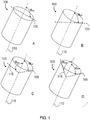
- FIGs. 1A-1D illustrates a variety of tubular cutting head configurations that can be fabricated from stock tube, according to some embodiments.
- FIG. 1A shows a cutting head stock tube 100 having a first plane 105 at an angle, ⁇ FP, that is orthogonal to the central axis 110 of the lumen of the stock tube 100.
- FIG. 1B shows a cutting head stock tube 100 having a first plane 105 at an acute angle, ⁇ FP , to the central axis 110 of the lumen of the stock tube 100, the acute angle ranging from 1° to about 75°.
- FIG. 1A shows a cutting head stock tube 100 having a first plane 105 at an angle, ⁇ FP, to the central axis 110 of the lumen of the stock tube 100, the acute angle ranging from 1° to about 75°.
- FIG. 1C shows a cutting head stock tube 100 having a first plane 105 at an acute angle, ⁇ FP , to the central axis 110 of the lumen of the stock tube 100, the acute angle, ⁇ FP , ranging from 1° to about 75°; and, having a second plane 105 at an angle, ⁇ SP , that is orthogonal to the central axis 110 of the lumen of the stock tube 100.
- 1D shows a cutting head stock tube 100 having a first plane 105 at an acute angle, ⁇ FP , to the central axis 110 of the lumen of the stock tube 100, the acute angle ranging from 1° to about 75°; and, having a second plane 105 at an angle, ⁇ SP, to the central axis 110 of the lumen of the stock tube 100, the acute angle, ⁇ SP , ranging from 1° to about 75°.
- the cutting head can be fabricated from any material known to one of skill to be suitable in a surgical environment for the uses taught herein.
- a hard material with hardness greater than Rockwell C 30 or greater than Rockwell C 45 can be suitable in some embodiments.
- the cutting head can be comprised of a component selected from the group consisting of tempered steel, stainless steel , high carbon steel , titanium or titanium alloy, ceramic, diamond and obsidian.
- the stainless steel can comprise 304 stainless steel, 316 stainless steel, 17-4 PH stainless steel, 400 series stainless steel, or any other stainless steels known to one of skill to be suitable for the cutting functions taught herein.
- the cutting head can be made of cobalt chromium, tungsten carbide, or a ceramic.
- the tube forming the cutting head can have a wall thickness, for example, from 0.08 mm to 0.51 mm (0.003" to 0.020") or more specifically 0.13 mm to 0.30 mm (0.005" to 0.012").
- the cross-sectional area of the cutting head can range from 3.05 mm 2 to 38.1 mm 2 (0.120 inches 2 to 1.5 inches 2 ) or, in some embodiments, from 4.57 mm 2 to 10.2 mm 2 (0.180 in 2 to 0.400 in 2 ).
- the width in any direction can range from 0.20 mm to 10.2 mm (0.080" to 0.400") or more and, in some embodiments, 0.41 mm to 0.64 mm (0.160" to 0.250").
- the cutting head can have a maximum transverse cross section dimension ranging from about 3.0mm to about 20.0mm, from about 4.0mm to about 15.0mm, from about 4.0mm to about 12.0mm, from about 5.0mm to about 10.0mm, about 5.0mm to about 8.0mm, or any range therein in increments of 0.1mm.
- the cutting heads have diameters of about 4.8mm, about 5.0mm, about 5.2mm, about 5.4mm, about 5.8mm, about 6.0mm, about 6.2mm, about 6.4mm, about 6.6mm, about 6.8mm, about 7.0mm, about 7.2mm, about 7.4mm, about 7.6mm, about 7.8mm, about 8.0mm, about 8.2mm, and any 0.1mm increment therein.
- the distal perimeter of a cutting head can be on the first plane or the second plane, or a combination thereof, and the cutting surfaces can be any cutting surface known to one of skill, such as a razor surface, a serrated surface, or a sinusoidal surface, in some embodiments.
- the cutting surface can have teeth and gullets between the teeth.
- the spacing between the teeth can be equal or variable, and the depth of the gullets can be equal or variable, and any combination of teeth and gullets can be used.
- the direction of the protrusion of the teeth can be offset from the direction of the remainder of the walls of the cutting head.
- the teeth are in the same direction as the remainder of the walls of the cutting head, such that the teeth are merely an extension of the walls of the cutting head, with no shift in direction toward the lumen of the cutting head or away from the lumen of the cutting head.
- the pattern can be a sequence of toward, away, toward, away, no shift, and the sequence is repeated around the distal edge of the outer perimeter of the cutting head.
- all teeth can point toward the lumen, and in some embodiments, all teeth can point away from the lumen.
- the teeth alternate toward the lumen and away from the lumen tooth-by-tooth.
- the teeth are gradually toward and away from the lumen at gradually increases and decreasing angles, tooth-by-tooth, to create an appearance of waves as the teeth circle the distal edge of the outer perimeter.
- the sequence can also be entirely random.
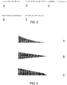
- FIGs. 2A-2E show blade configurations, according to some embodiments.
- FIG. 2A shows a 5 tooth shift pattern of toward, away, toward, away, no shift, repeat.
- FIG. 2B shows a random shift pattern.
- FIG. 2C shows a wavy shift pattern.
- FIG. 3D shows a 3 tooth shift pattern of away, toward, no shift, repeat.
- FIG. 3E shows a simple away, toward, repeat shift pattern.
- the choice of blade configuration can be combined with a choice of blade profile, in some embodiments.
- the cutting heads taught herein can have a variety cutting actions, such as a chisel action, sawing action, slicing action, and ripping action, for example.
- the blade profile chosen can be varied to use any blade profile known to one of skill.
- the teeth are beveled.
- the cutting heads have teeth that point backward as well as forward to include forward cutting surfaces in addition to backward cutting "spurs.”
- the teachings include a tubular cutting head for removing a target tissue of a subject.
- the tube can be an elongated, tubular structure of any shape, such as circular tube, a square tube, a rectangular tube, an elliptical tube, a pentagonal tube, a hexagonal tube, heptagonal, an octagonal tube, and the like, such that any number of sides, curvatures, or combinations thereof can be used in some embodiments.
- a circular tube is used.
- the cutting heads can have a combination of blade types, for example, forward-cutting blades, backward-cutting blades, and transverse cutting blades, as well as protrusions, hooks, and the like, for grabbing, ripping, or otherwise removing tissue.
- the cutting head can have a backward cutting blade for cutting the target tissue in a backward stroke of the cutting head, a transverse cutting blade for cutting the target tissue in a transverse stroke of the cutting head, or a combination thereof.
- a transvers utting blade can be positioned on the blade guard for cutting the target tissue in a transverse stroke of the cutting head.
- FIGs, 3A-3C show cross section of individual blade profiles, according to some embodiments.
- FIG. 3A shows a planar-concave blade profile.
- FIG. 3B shows a wedge blade profile.
- FIG. 3C shows a chisel blade profile.
- the blades can be designed to have any configuration, including a single-edge, double-edge, single barb, double-barb, straight tip, barbed tip, and the like, to assist with any form of tissue removal, including cutting, slicing, chiseling, scraping, gouging, sawing, grinding, and ripping of a tissue for efficiency in removal during a surgery, for example.
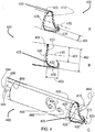
- FIGs. 4A-4C illustrate a cutting head, according to some embodiments in accordance with the invention.
- FIG. 4A shows an oblique view of the cutting head
- FIG. 4B shows a lateral view.
- the cutting head 400 can have an outer perimeter 405 that circumscribes a lumen 410 through the cutting head 400, the lumen 410 having a central axis 415.
- the cutting head 400 can also have a forward cutting blade 420 on a distal edge 425 of the outer perimeter 405, the forward cutting blade 420 configured for (i) cutting a target tissue (not shown) in a forward stroke of the cutting head 400 and (ii) directing the cut tissue into the lumen 410.
- the cutting head 400 can also have a blade guard 430 positioned distal to the forward cutting blade 420 and configured to guard a perimeter tissue (not shown) from the forward cutting blade 420 upon the forward stroke the blade guard 430 having a width 433 that is smaller than the width 422 of a transverse cross-section of the lumen 410 to facilitate entry of the target tissue into the lumen 410 on the forward stroke.
- the lateral surfaces 409 of the blade guard can also be serrated, or otherwise sharp cutting surfaces, for transverse cutting.
- FIG. 4C also shows such a surgical, tissue removal system that includes a tubular cutting head 400 for removing a target tissue (not shown) of a subject.
- the system can include a cutting head 400 having an outer perimeter that circumscribes a flow of suction 444 through the cutting head 400; a lumen 415 circumscribed by the outer perimeter 405, the lumen 410 guiding the flow of suction 444 and having a central axis 415; a forward cutting blade 420 on a distal edge 425 of the outer perimeter 405, the forward cutting blade 420 configured for (i) cutting the target tissue in a forward stroke of the cutting head 400 and (ii) directing the cut tissue into the lumen 410; and, a blade guard 430 positioned distal to the forward cutting blade 420 and configured to guard a perimeter tissue (not shown) from the forward cutting blade 420 upon the forward stroke the blade guard 430.
- the cutting head can be configured for an operable communication between the lumen 410 and a source of the suction 444, such that the systems 400 include the suction assembly 484 in operable communication with the cutting head 400 for creating the flow of suction 444 for removing the target tissue through the lumen 410 and out of the subject, the suction assembly 484 comprising a rigid suction tube 488 with a central axis.
- the operable communication includes the use of one or more suction ports 466 positioned just proximal to the most proximal point of the distal edge of the out perimeter of the cutting head.
- the one or more suction ports 466 can be located from about 3mm to about 20mm proximal to the most proximal point of the distal edge 425. While not intended to be bound by any theory or mechanism of action, one of skill will appreciate that a source of additional air can be useful when suctioning within a region that can create vacuum which would otherwise impede or cease the flow of suction that transports excised tissue away from the surgical space during the removal of the tissue.
- the suction ports 466 can be used to provide the additional air to avoid creating of the vacuum in the surgical space.
- the suction assembly 484 comprises an at least substantially rigid suction tube 488 having a proximal end (not shown) and a distal end 499, the distal end 499 in the operable communication with the cutting head 400, and the distal end 499 configured for communicating with a source of suction 444 for the suction assembly 484.
- the at least substantially rigid suction tube 488 can be formed as a single unit with the cutting head 400.
- the phrase, "at least substantially rigid" can refer a component that is rigid, or sufficiently rigid such that the desired function is obtained, under the forces that are created with normal use.
- a desired function may be to prevent or inhibit the occurrence of a bending moment of the rigid component at one or more points along the length of a rigid suction tube upon use of the cutting head in the subject.
- the following table describes the dimensional ratios of the cutting head 400 that were found to facilitate fast-and-efficient tissue removal in a discectomy.
- the "Label” is used to show the components and measures that form the ratios in a small device and a large device.
- the rigid suction tube can comprise any material known to one of skill to be suitable for the uses taught herein.
- the rigid suction tube can comprise any surgical steel, plastic or resin considered desirable to one of skill for the devices taught herein.
- the rigid suction tube can comprise the same or similar materials as the cutting head.
- the rigid suction tube can comprise a stainless steel, polyetheretherketone (PEEK), polyimide, or carbon fiber.
- the wall thickness of the shaft can be any thickness at which a select material will have the physical properties desired. In some embodiments, the wall thickness can range, for example, from 0.008 mm to 0.51 mm (0.003" to 0.020") and from 0.13 mm to 0.25 mm (0.005" to 0.010") in some embodiments.
- the luminal surface of the tube can be coated with TEFLON, a hydrophobic coating such as parylene, or a hydrophilic coating such as polyvinyl alcohol or polyethylene glycol.
- the rigid suction tube can comprise a polymer tube reinforced with a metal braid, a coiled tube, or a tube with transverse slots to facilitate articulation, should articulation be desired in some embodiments.
- the cutting head can be angled relative to the axis of the rigid suction tube by, for example, pulling on a tendon attached to the cutting head on one side, the tendon running-along a guide on the side of the rigid suction tube.
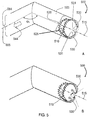
- FIGs. 5A and 5B illustrate the angulation of a cutting head 500, according to some embodiments in accordance with the invention.
- FIG. 5A shows that the central axis 515 of the lumen 510 can be at an angle, ⁇ 1 , ranging from about 5° to about 90° from a central axis 555 of the flow of suction 544 at the distal end 599 of the suction assembly (partially shown) 584, and the forward cutting blade 520 can be located about 2mm to about 25mm from the vertex of the angle, ⁇ 1 .
- ⁇ 1 can range from about 2mm to about 30mm, from about 2mm to about 30mm, from about 2.5mm to about 25mm, from about 3mm to about 25mm, from about 4mm to about 20mm, from about 5mm to about 15mm, from about 3mm to about 25mm, from about 7mm to about 12mm, from about 8mm to about 10mm, or any range therein in increments of 0.5mm.
- the central axis of the lumen is at an angle, ⁇ 1 , ranging from about 5° to about 90° from the central axis of the rigid suction tube, and the forward cutting blade is located about 3mm to about 25mm from the vertex of the angle, ⁇ 1 .
- the central axis of the lumen has a point of exit at the forward cutting blade, and the point of exit is located at a transverse distance of about 3mm to about 25mm that is orthogonal to the central axis of the rigid suction tube
- the central axis of the lumen is at an angle, ⁇ 1 , ranging from 1° to 180° from a central axis of the flow of suction at the distal end of the suction assembly, and the forward cutting blade is located 3mm to 25mm from the vertex of the angle, ⁇ 1 .
- additional angle, ⁇ 3 is located 5mm to 25mm proximal to ⁇ 1 , and angles ⁇ 1 and ⁇ 3 are independently selected to range from about 0° to about 180°, with the limitation that (i) the net angle, ⁇ 4 , between the central axis of the lumen of the cutting head and the central axis of a rigid suction tube located proximal to ⁇ 3 ranges from 0° to 90°; and, (ii) the distance between the central axis of the lumen of the cutting head and the central axis of the rigid suction tube ranges from 2mm to 30mm.
- the distance in the flow of suction between angles ⁇ 1 and ⁇ 3 can range from about 5mm to about 30mm, from about 5mm to about 25mm, from about 5mm to about 20mm, from about 6mm to about 18mm, from about 7mm to about 15mm, or any range or distance therein in increments of 1mm.
- the operable communication between the cutting head 500 and the suction assembly 584 can be articulating, and the angle, ⁇ 1 , can be adjustable.
- the operable communication between the cutting head 500 and the suction assembly 584 can be rigid, and the angle, ⁇ 1 , can be fixed.
- the angle, ⁇ 1 can range from 0° to about 45°, from about 1° to about 40°, from about 5° to about 35°, from 10° to about 35°, from 15° to about 40°, from 20° to about 30°, or any range therein in increments of 1°.
- the angle, ⁇ 1 can be about 3°, about 5°, about 10°, about 15°, about 20°, about 25°, about 30°, about 35°, about 40°, about 45°, or any angle therein in increments of 1°.
- the backward cutting blade can be positioned on the distal edge 525 of the outer perimeter 505 for cutting the target tissue in the backward stroke of the cutting head 500.
- the backward cutting blade 531 can be positioned on the blade guard 530 for cutting the target tissue in the backward stroke of the cutting head 500.
- FIG. 5B shows that the blade guard 530 can have a double-edged blade tip as the backward cutting blade 531 point back into the lumen 515 at an angle, ⁇ 2 , of greater than 90° from the central axis 515 of the lumen 500 to trap and/or cut tissue in the lumen 510 in the backwards stroke of the cutting head 500.
- the backward cutting blade 531 can be referred to as a "talon” in some embodiments, or "pincer", as it can function to grab, shear, and hook tissue for removal.
- the target tissue can be a nucleus pulposus
- the perimeter tissue can be an annulus fibrosis, for example.
- a surgical, tissue removal system for a discectomy can comprise a tubular cutting head for removing a nucleus pulposus from a subject.
- the systems can include a cutting head having an outer perimeter that circumscribes a flow of suction through the cutting head; a lumen circumscribed by the outer perimeter, the lumen guiding the flow of suction; a forward cutting blade on a distal edge of the outer perimeter, the forward cutting blade configured for (i) cutting the nucleus pulposus in a forward stroke of the cutting head and (ii) directing the cut nucleus pulposus into the lumen; a backward cutting blade for cutting the nucleus pulposus in a backward stroke of the cutting head; a transverse cutting blade for cutting the nucleus pulposus in a transverse stroke of the cutting head; and, a blade guard positioned distal to the forward cutting blade and configured to guard an annulus fibrosis tissue from the forward cutting blade upon the forward stroke.
- the devices taught herein can operate without substantial clogging from the flow of excised tissue from the cutting head, and this was accomplished by design. Without intending to be bound by any theory or mechanism of action, it was discovered that the area of a transverse cross-section of the distal end of the cutting head should be at least substantially equal to, or less than, the transverse cross-sectional area of any point that is positioned proximal to the distal end of the cutting head leading to collection of the flow of excised tissue from the cutting head.
- Such points would include, for example, any such point of cross-section along the rigid suction tube, or any other component of the section assembly leading to the point of collection of the excised tissue, for example, the most proximal orifice at which the pressure difference dumps the excised tissue into a collection canister in some embodiments.
- the term "at least substantially equal to” means that there may be a smaller transverse cross-sectional area, as long as it is limited in magnitude, in some embodiments.
- the transverse cross-sectional area can be at least substantially equal to the transverse cross-sectional area of the cutting head if it is no more than 20% less in transverse cross-sectional area at the proximally located cross-section.
- the transverse cross-sectional area can be at least substantially equal to the transverse cross-sectional area of the cutting head if it is no more than about 3%, about 5%, about 7%, about 9%, about 11%, about 13%, about 15%, about 17%, about 19%, about 21% less in transverse cross-sectional area at the proximally located cross-section. Any percent therein in increments of 1%, less in transverse cross-sectional area at the proximally located cross-section.
- the teachings also include a method of removing a target tissue from a subject.
- the method can comprise creating an opening in a subject for access to a target tissue; inserting a cutting head taught herein through the opening to access the target tissue in the subject; imaging the depth of the tip of the cutting head using a suitable imaging technique, such as fluoroscopy; and, forcing the cutting head in a forward direction on a surface comprising the target tissue to remove the target tissue while vacuum is activated to suck cut tissue proximally.
- the forward direction can include a force vector that moves (i) at least substantially on a plane containing the central axis of the lumen of the cutting head, (ii) at least substantially on the surface comprising the target tissue, and (iii) toward the perimeter tissue that is protected by the blade guard.
- the method can include capturing the target tissue in the lumen of the cutting head, as well as removing the target tissue through the lumen and out of the subject.
- the phrase, "at least substantially on...,” can refer to a position or movement that is sufficient close to the exact desired position such that the desired function is obtained, under the forces and conditions that are created with normal use of the systems and devices taught herein.
- “at least substantially on a plane containing the central axis of the lumen of the cutting head” or at least substantially on the surface comprising the target tissue” can refer to a position or movement that is parallel or substantially parallel to the plane or surface but perhaps off by about 1um to about 15mm from the actual plane, or perhaps off by about 0.1° to about 20° in direction of movement.
- the measure of "at least substantially” is used to approximate situations in which the exact measure or position is not obtained, but function desired by a person of ordinary skill is obtained.
- a reduction of outcome when compared to the best possible outcome can be used to determine what is "at least substantially" the desired outcome.
- the desired outcome is at least substantially obtained where the best possible outcome is reduced by less than 10%, less than 15%, less than 20%, less than 30%, less than 40% or less than 50%.
- the desired outcome is at least substantially obtained where the best possible outcome is reduced by an amount of about 5% to about 30%, about 7% to about 35%, about 10% to about 25%, or any range therein in increments of 1%.
- the opening in the subject can vary, depending on the disk height of the subject, which is often in the range of about 5mm-7mm. In some embodiments, the opening in the subject can range in size from about 4mm x 4mm to about 14mm x 14mm. In some embodiments, the opening can be about 10mm x 7mm.
- the method comprises forcing a cutting head taught herein in a backward direction on a surface comprising the target tissue to remove the target tissue.
- the backward direction can include a force vector that moves (i) at least substantially on a plane containing the central axis of the lumen of the cutting head, (ii) at least substantially on the surface comprising the target tissue, and (iii) away from the perimeter tissue that is protected by the blade guard.
- the method comprises forcing a cutting head taught herein in a transverse direction on a surface comprising the target tissue to remove the target tissue.
- the transverse direction can include a force vector that moves (i) at an angle ranging from about 15° to about 165° from a plane containing the central axis of the lumen of the cutting head, (ii) at least substantially on the surface comprising the target tissue, and (iii) in contact with the perimeter tissue that is protected by the blade guard.
- the cutting heads taught herein are sharp and can be harmful to tissues during entry and exit of the cutting heads through the surgical opening.
- An obturator, guard cannula is provided in some embodiments to protect a subject during entry and exit of an elongated surgical cutting device having a non-linearity.
- FIG. 6 illustrates an obturator, guard cannula, according to some embodiments.
- the guard cannula 600 can comprise an entry hub 605 having an inner perimeter 615, an outer perimeter 625, and an irrigation port 635 that communicates between the inner perimeter 615 with the outer perimeter 625; and, a linear, elongated split-tube 650 having a proximal end 655, a distal end 665, and a lumen 675.
- the proximal end 655 of the split-tube 650 can (i) circumscribe at least a portion of the inner perimeter 615 of the hub 605 and (ii) be in operable communication with the irrigation port 635.
- the communication can be operable to receive an irrigation fluid 690 from the irrigation port 635, the transport of the irrigation fluid 690 to a target tissue (not shown) including, for example, a movement of the irrigation fluid 690 from the irrigation port 635 to the distal end 665 of the split-tube 650 on a luminal surface 680 of the split-tube 650.
- the irrigation fluid can be any fluid desired by one of skill, including liquids and gases.
- the irrigation fluid can be aqueous.
- the irrigation fluid can be non-aqueous.
- the irrigation fluid can be an emulsion.
- the irrigation fluid can comprise a gas.
- aqueous irrigation fluids include water, saline, or an aqueous surfactant containing liquid.
- non-aqueous fluids can include any oilbased liquid that may help facilitate tissue extraction during a surgical procedure.
- gases can include carbon dioxide, nitrogen, air, and any inert or at least substantially nonreactive gases.
- the irrigation fluid can include a lubricant, such as glycerin, silicon oil, and the like.
- Irrigation fluids can be used as a carrier to help remove an excised tissue, or to help inhibit the creation of a vacuum within a surgical site that can inhibit the removal of the excised tissue.
- An example of such as a vacuum is one that may be created during use of a suction within a closed cavity such as an intervertebral space within an annulus during a discectomy.
- the distal end 665 of the split-tube 650 can also have any configuration desired by one of skill.
- the distal end 665 can be at least substantially pointed and/or non-blunt.
- the distal end 665 can be at least substantially blunt to avoid damage to an entry tissue upon contact of the distal end 665 with the entry tissue.
- the split-tube 650 can also have a length ranging from about 10cm to about 60 cm and a width ranging from about 5mm to about 16mm.
- the split in the split-tube 650 can compose a gap 667 having a width ranging from about 4mm to about 14mm, the split accommodating a non-linearity in the surgical device.
- the cutting heads taught herein can have a diameter that is smaller than that of the portion of the suction assembly that passes through the lumen of the guard cannula, such that the guard cannula holds the suction assembly 484 but allows the cutting head 400 to pass through the gap 667.
- the gap 667 can have a width that exceeds the diameter of the cutting head 400 but is less than the diameter of the rigid suction tube 488, and the lumen of the guard cannula 600 has a diameter that exceeds the diameter of the rigid suction tube 488.
- the systems taught herein can be used in a variety of procedures for removal of a target tissue from a subject including, for example, removal of a meniscus or a discectomy.
- the surgical cutting device used with the guard cannula can be a discectomy device.
- the entry tissue includes the subject's epithelial tissue, muscle tissue, nerve tissue, connective tissue, a blood vessel, bone, cartilage, or a combination thereof, leading to the nucleus pulposus.
- the target tissue can include the nucleus pulposus in some embodiments.
- kits having a surgical tissue removal system and a guard cannula is provided, the kit using any combination of system and cannula embodiments taught herein.
- the kits can be a discectomy kit.
- the entry tissue includes the subject's epithelial tissue, muscle tissue, nerve tissue, connective tissue, a blood vessel, bone, cartilage, or a combination thereof, leading to the nucleus pulposus.
- the target tissue can include the nucleus pulposus in some embodiments.
- FIG. 7 illustrates a surgical tissue removal kit, according to some embodiments.
- the kit 700 includes a cutting head 400, a suction assembly 484, and an obturator, guard cannula 600.
- a flow of suction 444 from the suction assembly 484 enters the cutting head 400 to remove a target tissue excised by the cutting head.
- Irrigation water 690 can enter irrigation valve 795 and/or the irrigation port 635, the irrigation water 690 coming from the irrigation valve 795 is used when the suction 444 is off, and the irrigation water 690 coming from the irrigation port 635 can be used when the suction 444 is on, during which the suction 444 draws the irrigation water 690 between the luminal surface of the guard cannula 600 and the suction assembly 484 into the surgical area (not shown).
- the guard cannula 600 protects the entry tissue (not shown) while the cutting head 400 and suction assembly 484 moves relative to the entry tissue during a surgical procedure, the cutting head 400 moving, for example, in a forward, backward, and/or transverse motion to excise and remove the target tissue.
- kits to remove a target tissue comprises creating an opening in a subject for access to a target tissue; inserting the cutting head of the kit through the entry hub and the elongated split-tube of the guard cannula of the kit; inserting the cutting head of the kit through the opening to access the target tissue in the subject while protecting the entry tissue with the blunt, distal end of the split-tube.
- methods of using the tissue removal systems are the same or similar to those taught herein.
- the target tissue can be a nucleus pulposus
- the perimeter tissue can be an annulus fibrosis.
- a kit with a guard cannula that helps protect the subject's epithelial tissue, muscle tissue, nerve tissue, connective tissue, a blood vessel, bone, cartilage, or a combination thereof, leading to the nucleus pulposus in such procedures.
- FIGs. 8A-8C illustrate a system or kit that can irrigate concurrent with application of suction, and without the obturator, guard cannula in place, according to some embodiments.
- FIG. 8A shows the complete discectomy system 800 including the cutting head 400, a means for applying suction through the suction assembly 884, a control handle 886 and a vacuum attachment 892, an irrigation tube 804, an irrigation control 802, and an optional vacuum control 888.
- the handle 886 can have a knob (not shown) that turns to tension a pull cable to flex or straighten the cutting head relative to the rigid suction tube, or a slide that tensions the cable to flex or straighten the cutting head relative to the rigid suction tube.
- the cables to flex and straighten can be on opposing sides of the shaft constrained to small side lumens attached to the outer surface of the shaft to flex and straighten out the cutting head.
- FIG. 8B shows a cross-sectional view of the irrigation tube 804 relative to the rigid suction tube 894.
- FIG. 8C shows a cross-sectional view of the control handle 886 and internal piping.
- a variety of cutter heads were tested in 3 cadaver laboratories on 28 discs. The results were compared to determine the most efficient cutter head design.
- a desirable cutter head design was one that would cut well on all target tissues, including the nucleus pulposus, vertebral endplates, and inner annulus tissue.
- the cutter head should also cut the target tissues in a desired manner while providing little to no damage to the perimeter tissue, such tissue including the perimeter annulus fibrosis tissue that should be preserved as a desirable perimeter structure.
- the design should remove tissue quickly under suction, such that the configuration of the head facilitates the removal of the tissue under suction.
- FIGs. 9A-9G show cutting head designs that were tested, according to some embodiments.
- the design in FIG. 9A cut well but it was not as safe to the annulus as other designs.
- the design in FIG. 9B was safe to the annulus but it did not cut tough tissue well and showed too much resistance.
- the design in FIG. 9C also did not penetrate tough tissue well.
- the design in FIG. 9D did cut and decorticate well, but it clogged on soft/elastic tissue.
- the design in FIG. 9E cut tough tissue well and did not clog, and it also decorticates really well. It was also safe to the annulus. The shape of the device however, did not reach the far side of the nucleus pulposus.
- the design in FIG. 9A cut well but it was not as safe to the annulus as other designs.
- the design in FIG. 9B was safe to the annulus but it did not cut tough tissue well and showed too much resistance.
- the design in FIG. 9C also did not penetrate tough tissue well.
- FIG. 9F shows a bend that was introduced to the device to enable the cutting head of FIG. 9E to reach the far side of the nucleus pulposus.
- the design in FIGs. 9G and 9H showed the most efficient cutting head performance identified in the testing, removing 23cc of material in 5 minutes.
- This example further developed the designs of the cutting heads.
- the design in FIGs. 8G and 8H were further investigated in 7 cadaver labs and 28 discs.
- FIGs. 10A-10E illustrate the advancements in the cutting head, according to some embodiments.
- the design in FIG. 10A shows a cutting head having a bevel on the outer surface of the cutting teeth, and the device cut poorly and gouged soft bone.
- the design in FIG. 10B shows an oval cutting head not having the bevel on the outer surface of the cutting teeth, and the device had inconsistent cutting and gouged soft bone.
- the design in FIG. 10C was shown for a comparison result using a ring curette, and the device gouged soft bone.
- the design in FIG. 10D shows a short cutting head with a single "talon" or pincer, and the device showed the most appealing results to date with optimal cutting and no gouging.
- FIG. 10E is another proposed design, configured to perform with the efficiency of the design of FIG. 10D , with the addition of a second talon that bends away from the lumen of the cutting head to serve as an additional talon and blade guard.
- This example describes an alternate embodiment that was tested, referred to as the serpentine or bayonet configuration, in which the rigid suction tube 488 can have at least two angles; an angle ⁇ 1 , and an angle ⁇ 3 .
- FIGs. 11A-11C illustrate a bayonet-type communication between a cutting head and a suction assembly, according to some embodiments. It was discovered that the distal end of the rigid suction tube 488 can be redirected in bayonet, or serpentine, fashion in order to facilitate an improved access of the cutting head to a target tissue during a discectomy, for example. As shown in FIGs.
- Angles ⁇ 1 and ⁇ 3 can each be independently selected to range from about 0° to about 180°, with the limitation that (i) the net angle, ⁇ 4 , that is realized between the central axis 415 of the lumen 410 of the cutting head 400 and the central axis 497 of the rigid suction tube 488 (extended as directed proximal to ⁇ 1 ) ranges from 0° to 90°; and, (ii) the distance 498 between the central axis 415 of the lumen 410 of the cutting head 400 and the central axis 497 of the rigid suction tube 488 can range from about 2mm to about 30mm.
- the central axis of the lumen can have a point of exit at the forward cutting blade, and the point of exit is located at a transverse distance of about 3mm to about 25mm
- the distance 498 can be about 2mm, about 3mm, about 4mm, about 5mm, about 6mm, about 7mm, about 8mm, about 9mm, about 10mm, about 12mm, about 14mm, about 16mm, about 18mm, about 20mm, about 22mm, about 24mm, about 26mm, about 28mm, about 30mm, and any distance or range therein in increments of 0.5mm.
- the distance between the vertex of ⁇ 3 and the distal end of the cutting head 400 can range from about 5mm to about 25mm, from about 6mm to about 20mm, from about 7mm to about 15mm, or any range therein in increments of 1mm.
Claims (15)
- Système chirurgical d'enlèvement de tissus pour l'enlèvement d'un tissu cible d'un sujet, le système comprenant une tête de coupe (400) présentant :un périmètre extérieur (405) qui circonscrit une lumière (410) à travers la tête de coupe (400), la lumière (410) présentant un axe central (415) ; etune lame de coupe de recul (531) configurée en tant que talon pour la découpe de tissu selon une course de recul de la tête de coupe (400) et pour crocheter le tissu à enlever, selon lequel la lame de coupe de recul (531) est positionnée sur un bord distal du périmètre extérieur (405).
- Système selon la revendication 1, comprenant en outre une lame de coupe d'avancée (420) sur un bord distal du périmètre extérieur, la lame de coupe d'avancée (420) étant configurée pour découper un tissu cible selon une course vers l'avant de la tête de coupe (400) et pour diriger le tissu découpé dans la lumière (410).
- Système selon la revendication 2, comprenant en outre un protège-lame (430) positionné de manière distale par rapport à la lame de coupe d'avancée (420) et configuré pour protéger un tissu de périmètre de la lame de coupe d'avancée (420) lors de la course vers l'avant, le protège-lame présentant une largeur plus petite que la largeur d'une section transversale de la lumière (410) afin de faciliter l'entrée du tissu cible dans la lumière lors de la course vers l'avant.
- Système selon la revendication 3, selon lequel la lame de coupe de recul (531) est positionnée sur le protège-lame (430) pour la découpe du tissu cible selon une course de recul de la tête de coupe (400).
- Système selon l'une quelconque des revendications 1 à 4, selon lequel la tête de coupe (400) présente une lame de coupe transversale pour la découpe du tissu cible selon une course transversale de la tête de coupe (400).
- Système selon l'une quelconque des revendications 1 à 3, ou la revendication 4, selon lequel la lame de coupe transversale est positionnée sur la lame de coupe de recul (531) pour la découpe du tissu cible selon une course transversale de la tête de coupe (400).
- Système selon la revendication 5, lorsque dépendante de la revendication 3 ou 4, selon lequel la tête de coupe (400) présente une lame de coupe transversale sur le protège-lame (430) pour la découpe du tissu cible selon une course transversale de la tête de coupe (400).
- Système selon l'une quelconque des revendications précédentes, selon lequel la tête de coupe (400) est en outre configurée pour une communication opérante entre la lumière (410) et une source d'aspiration (444) ; et comprenant en outre :
un ensemble d'aspiration (484) en communication opérante avec la tête de coupe (400), l'ensemble d'aspiration (484) fournissant la source d'aspiration (444) et comprenant au moins un tube d'aspiration sensiblement rigide (488) présentant un axe central et créant le flux d'aspiration pour l'enlèvement du tissu cible à travers la lumière (410) et en dehors du sujet. - Système selon la revendication 8, selon lequel le au moins un tube d'aspiration sensiblement rigide (488) se présente sous forme d'unité unique avec la tête de coupe (400).
- Système selon la revendication 8, selon lequel la communication opérante entre la tête de coupe (400) et l'ensemble d'aspiration (484) est articulée, et l'angle θ1, est ajustable.
- Système selon l'une quelconque des revendications 8 à 10, lorsque dépendante de la revendication 2, selon lequel l'axe central (415) de la lumière (410) présente un point de sortie avant au niveau de la lame de coupe d'avancée (420), et le point de sortie se situe à une distance transversale de 3 mm à 25 mm de manière orthogonale à l'axe central du tube d'aspiration rigide (488).
- Système selon l'une quelconque des revendications 8 à 11, lorsque dépendante de la revendication 2, selon lequel l'axe central (415) de la lumière (410) se situe à un angle, θ1, variant de 5° à 90° par rapport l'axe central du tube d'aspiration rigide (488), et la lame de coupe d'avancée (420) se situe à 3 mm à 25 mm du vertex de l'angle, θ1.
- Système selon l'une quelconque des revendications 8 à 11, lorsque dépendante de la revendication 2, selon lequel l'axe central (415) de la lumière (410) se situe à un angle, θ1, variant de 1° à 180° par rapport l'axe central du tube d'aspiration rigide (488), et la lame de coupe d'avancée (420) se situe à 3 mm à 25 mm du vertex de l'angle, θ1, selon lequel :un angle additionnel, θ3, se situe à 5 mm à 25 mm de manière proximale à θ1;les angles θ1 et θ3 sont choisis indépendamment l'un de l'autre pour varier de 0° à 180°, sous réserve de la limitation que :l'angle net, θ4, entre l'axe central (415) de la lumière (410) de la tête de coupe (400) et l'axe central du tube d'aspiration rigide (488) situé de manière proximale à θ3, varie de 0° à 90° ; etl'axe central (415) de la lumière (410) présente un point de sortie au niveau de la lame de coupe d'avancée (420), et le point de sortie se situe à une distance transversale de 3 mm à 25 mm de manière orthogonale à l'axe central du tube d'aspiration rigide (488).
- Système selon la revendication 8, selon lequel la communication opérante entre la tête de coupe (400) et l'ensemble d'aspiration (484) est rigide, et l'angle θ1, est fixe.
- Système selon la revendication 1, selon lequel :la tête de coupe (400) est configuré pour une communication opérante entre la lumière et une source d'aspiration (444) ; et comprenant en outre :un ensemble d'aspiration (484) en communication opérante avec la tête de coupe (400), l'ensemble d'aspiration (484) fournissant la source d'aspiration (444) et comprenant au moins un tube d'aspiration sensiblement rigide (488) présentant un axe central et créant le flux d'aspiration pour l'enlèvement du tissu cible à travers la lumière (410) et en dehors du sujet ; etune canule obturatrice de protection (600) pour protéger un sujet lors de l'introduction et du retrait du système chirurgical d'enlèvement de tissu, la canule de protection (600) comprenant :un moyeu d'entrée (605) présentant un périmètre intérieur (615), un périmètre extérieur (625), et un port d'irrigation (635) qui communique entre le périmètre intérieur (615) et le périmètre extérieur (625) ; etun tube fendu linéaire allongé (650) présentant une extrémité proximale (655) et une extrémité distale (665) et une lumière (675) ; selon lequell'extrémité proximale (655) du tube fendu (650) circonscrit au moins une partie du périmètre intérieur (615) du moyeu (605) ; etest en communication opérante avec le port d'irrigation (635), opérable pour recevoir un fluide d'irrigation (690) en provenance du port d'irrigation (635), le transport du fluide d'irrigation (690) vers un tissu cible comportant un mouvement du fluide d'irrigation (690) depuis le port d'irrigation (635) vers l'extrémité distale (665) du tube fendu (650) sur une surface luminale (680) du tube fendu (650) ;l'extrémité distale (665) du tube fendu (650) est au moins sensiblement obtus pour éviter tout dommage envers un tissu d'entrée lors d'un contact de l'extrémité distale (665) avec le tissu d'entrée ;le tube fendu (650) présente une longueur de 10cm à 60 cm et une largeur de 5 mm à 16 mm ; etla fente dans le tube fendu (650) forme un espace présentant une largeur variant de 4 mm à 14 mm, la fente s'accommodant d'une absence de linéarité dans le dispositif chirurgical.
Applications Claiming Priority (4)
| Application Number | Priority Date | Filing Date | Title |
|---|---|---|---|
| US201161566629P | 2011-12-03 | 2011-12-03 | |
| US201261596865P | 2012-02-09 | 2012-02-09 | |
| EP12853751.1A EP2785264B1 (fr) | 2011-12-03 | 2012-08-22 | Têtes de coupe sûres et systèmes destinés au prélèvement rapide d'un tissu cible |
| PCT/US2012/051952 WO2013081691A1 (fr) | 2011-12-03 | 2012-08-22 | Têtes de coupe sûres et systèmes destinés au prélèvement rapide d'un tissu cible |
Related Parent Applications (2)
| Application Number | Title | Priority Date | Filing Date |
|---|---|---|---|
| EP12853751.1A Division EP2785264B1 (fr) | 2011-12-03 | 2012-08-22 | Têtes de coupe sûres et systèmes destinés au prélèvement rapide d'un tissu cible |
| EP12853751.1A Division-Into EP2785264B1 (fr) | 2011-12-03 | 2012-08-22 | Têtes de coupe sûres et systèmes destinés au prélèvement rapide d'un tissu cible |
Publications (2)
| Publication Number | Publication Date |
|---|---|
| EP3011918A1 EP3011918A1 (fr) | 2016-04-27 |
| EP3011918B1 true EP3011918B1 (fr) | 2018-07-25 |
Family
ID=48524529
Family Applications (2)
| Application Number | Title | Priority Date | Filing Date |
|---|---|---|---|
| EP12853751.1A Active EP2785264B1 (fr) | 2011-12-03 | 2012-08-22 | Têtes de coupe sûres et systèmes destinés au prélèvement rapide d'un tissu cible |
| EP15189482.1A Active EP3011918B1 (fr) | 2011-12-03 | 2012-08-22 | Têtes de coupe sans danger et systèmes permettant de retirer rapidement un tissu cible |
Family Applications Before (1)
| Application Number | Title | Priority Date | Filing Date |
|---|---|---|---|
| EP12853751.1A Active EP2785264B1 (fr) | 2011-12-03 | 2012-08-22 | Têtes de coupe sûres et systèmes destinés au prélèvement rapide d'un tissu cible |
Country Status (8)
| Country | Link |
|---|---|
| US (5) | US9220528B2 (fr) |
| EP (2) | EP2785264B1 (fr) |
| JP (2) | JP5723035B2 (fr) |
| KR (1) | KR20140109924A (fr) |
| CN (1) | CN103327913B (fr) |
| ES (1) | ES2564513T3 (fr) |
| HK (2) | HK1197964A2 (fr) |
| WO (1) | WO2013081691A1 (fr) |
Families Citing this family (25)
| Publication number | Priority date | Publication date | Assignee | Title |
|---|---|---|---|---|
| KR100962166B1 (ko) * | 2009-05-04 | 2010-06-10 | 주식회사 이노바이오써지 | 임플란트용 일체형 치조골절개 확장기 |
| ES2564513T3 (es) | 2011-12-03 | 2016-03-23 | Ouroboros Medical Inc. | Cabezales de corte seguros y sistemas para retirada rápida de un tejido diana |
| CN105578975A (zh) * | 2013-07-19 | 2016-05-11 | 欧罗波罗斯医学有限公司 | 用于真空辅助式组织移除系统的防堵塞装置 |
| US10646234B2 (en) * | 2013-08-07 | 2020-05-12 | Arthrex, Inc. | Meniscal probe cutter |
| CN104688300B (zh) * | 2013-12-09 | 2018-06-19 | 苏州点合医疗科技有限公司 | 一种脊柱数字化手术用髓核清理刀 |
| US10076315B2 (en) | 2014-09-18 | 2018-09-18 | Transmed7, Llc | Soft tissue biopsy or excisional devices and methods |
| CN104224250A (zh) * | 2014-09-28 | 2014-12-24 | 丁轶人 | 腹腔镜专用取脾器 |
| US20160158501A1 (en) * | 2014-12-04 | 2016-06-09 | David Farris | Percutaneous scalpel and tissue dilator |
| JP2016155488A (ja) * | 2015-02-25 | 2016-09-01 | トキワケミカル工業株式会社 | 合成樹脂芯材の製造方法 |
| US11185344B2 (en) | 2015-03-13 | 2021-11-30 | The Regents Of The University Of Michigan | Tool for neuroma treatment and nerve regeneration procedures |
| US10052128B2 (en) | 2015-08-24 | 2018-08-21 | Qathax, LLC | Catheter extraction |
| KR101863996B1 (ko) * | 2015-09-23 | 2018-06-01 | 황적희 | 세라믹 소재 커터의 인공 관절용 커터 어셈블리 |
| US9855675B1 (en) * | 2016-09-20 | 2018-01-02 | RELIGN Corporation | Arthroscopic devices and methods |
| US10773031B2 (en) * | 2017-08-09 | 2020-09-15 | WLB Interventional, LLC | Needle for subcision procedures |
| KR101979106B1 (ko) * | 2017-09-19 | 2019-05-15 | 황적희 | 최소 침습법 대응형 정형외과 시술용 관절 절삭을 위한 의료용 커터 툴 |
| CN108478257A (zh) * | 2018-03-19 | 2018-09-04 | 广东工业大学 | 一种软组织冲裁刀组 |
| KR102157064B1 (ko) * | 2018-06-08 | 2020-09-18 | 조선대학교산학협력단 | 가슴연골 채취기 |
| US10966734B2 (en) * | 2019-05-10 | 2021-04-06 | Warsaw Orthopedic, Inc. | Surgical instrument and method |
| KR102245306B1 (ko) * | 2019-05-23 | 2021-04-29 | 고려대학교 산학협력단 | 선택적 탈출 부위 제거 장치 |
| CN110269676B (zh) * | 2019-06-13 | 2021-07-06 | 河南科技大学第一附属医院 | 一种多功能肝胆胰外科临床用止血器 |
| US11464653B2 (en) * | 2019-06-30 | 2022-10-11 | Innovasis, Inc. | Minimally invasive surgery (MIS) methods and devices |
| US11253371B2 (en) | 2019-12-27 | 2022-02-22 | Henry F. Fabian, JR. | Vertebral body shaver assembly |
| CN112450997B (zh) * | 2020-11-14 | 2022-02-01 | 李振宙 | 一种经椎间孔镜下融合手术用器械及其使用方法 |
| US11523834B1 (en) | 2022-06-20 | 2022-12-13 | University Of Utah Research Foundation | Cartilage and bone harvest and delivery system and methods |
| US11660194B1 (en) | 2022-06-20 | 2023-05-30 | University Of Utah Research Foundation | Cartilage and bone harvest and delivery system and methods |
Family Cites Families (332)
| Publication number | Priority date | Publication date | Assignee | Title |
|---|---|---|---|---|
| US207932A (en) | 1878-09-10 | Improvement in surgical dilators | ||
| US177490A (en) | 1876-05-16 | Civilioh fqnbs and william j | ||
| US1749919A (en) | 1928-08-27 | 1930-03-11 | Ida B Mierley | Operating curette |
| FR84847E (fr) | 1962-12-04 | 1965-07-26 | ||
| US3404677A (en) * | 1965-07-08 | 1968-10-08 | Henry A. Springer | Biopsy and tissue removing device |
| US3774613A (en) | 1971-12-30 | 1973-11-27 | Scitron Corp | Suction curettage |
| US3955579A (en) | 1973-07-23 | 1976-05-11 | Henry Bridgman | Vacuum curet |
| US4061146A (en) | 1976-04-15 | 1977-12-06 | The United States Of America As Represented By The Administrator Of The National Aeronautics And Space Administration | Tissue macerating instrument |
| US4069824A (en) * | 1976-07-12 | 1978-01-24 | Weinstock Robert E | Method of and apparatus for forming a crescentic joint in a bone |
| DE2914455A1 (de) | 1979-04-10 | 1980-10-23 | Maschf Augsburg Nuernberg Ag | Vorrichtung zur herstellung einer aushoehlung in einem knochen |
| US4309777A (en) | 1980-11-13 | 1982-01-12 | Patil Arun A | Artificial intervertebral disc |
| US4545374A (en) | 1982-09-03 | 1985-10-08 | Jacobson Robert E | Method and instruments for performing a percutaneous lumbar diskectomy |
| US4603694A (en) | 1983-03-08 | 1986-08-05 | Richards Medical Company | Arthroscopic shaver |
| US4573448A (en) | 1983-10-05 | 1986-03-04 | Pilling Co. | Method for decompressing herniated intervertebral discs |
| ATE44871T1 (de) | 1984-09-04 | 1989-08-15 | Univ Berlin Humboldt | Bandscheibenendoprothese. |
| US4711238A (en) | 1985-03-14 | 1987-12-08 | Cunningham Frank W | Meniscal cutting device |
| DE3532653C2 (de) | 1985-09-13 | 1993-10-21 | Martin Kaltenbach | Dilatationskatheter |
| US4733665C2 (en) | 1985-11-07 | 2002-01-29 | Expandable Grafts Partnership | Expandable intraluminal graft and method and apparatus for implanting an expandable intraluminal graft |
| US4646738A (en) | 1985-12-05 | 1987-03-03 | Concept, Inc. | Rotary surgical tool |
| DE3637314A1 (de) | 1986-11-03 | 1988-05-11 | Lutz Biedermann | Platzhalter-implantat |
| DE8714069U1 (fr) | 1987-10-21 | 1987-12-03 | Richard Wolf Gmbh, 7134 Knittlingen, De | |
| US5529580A (en) | 1987-10-30 | 1996-06-25 | Olympus Optical Co., Ltd. | Surgical resecting tool |
| US4796642A (en) | 1987-12-28 | 1989-01-10 | Cordis Leads, Inc. | Pacing lead stylet |
| DE3809793A1 (de) | 1988-03-23 | 1989-10-05 | Link Waldemar Gmbh Co | Chirurgischer instrumentensatz |
| DE3906301A1 (de) | 1988-04-28 | 1989-12-14 | Olympus Optical Co | Chirurgisches resektionsinstrument |
| JPH065770Y2 (ja) * | 1988-04-28 | 1994-02-16 | オリンパス光学工業株式会社 | 外科用切除器具 |
| US5609635A (en) | 1988-06-28 | 1997-03-11 | Michelson; Gary K. | Lordotic interbody spinal fusion implants |
| US5556376A (en) | 1988-07-22 | 1996-09-17 | Yoon; Inbae | Multifunctional devices having loop configured portions and collection systems for endoscopic surgical procedures and methods thereof |
| US6120437A (en) | 1988-07-22 | 2000-09-19 | Inbae Yoon | Methods for creating spaces at obstructed sites endoscopically and methods therefor |
| DE8814573U1 (fr) | 1988-11-18 | 1990-01-11 | Effner Gmbh, 1000 Berlin, De | |
| US4969888A (en) | 1989-02-09 | 1990-11-13 | Arie Scholten | Surgical protocol for fixation of osteoporotic bone using inflatable device |
| US5078723A (en) | 1989-05-08 | 1992-01-07 | Medtronic, Inc. | Atherectomy device |
| US5030201A (en) | 1989-11-24 | 1991-07-09 | Aubrey Palestrant | Expandable atherectomy catheter device |
| US5074871A (en) | 1989-12-07 | 1991-12-24 | Evi Corporation | Catheter atherotome |
| US5221261A (en) | 1990-04-12 | 1993-06-22 | Schneider (Usa) Inc. | Radially expandable fixation member |
| US5100423A (en) | 1990-08-21 | 1992-03-31 | Medical Engineering & Development Institute, Inc. | Ablation catheter |
| DE4133073A1 (de) | 1990-10-11 | 1992-04-16 | Effner Gmbh | Trokar |
| DE4035146A1 (de) | 1990-11-06 | 1992-05-07 | Riek Siegfried | Instrument zum penetrieren von koerpergewebe |
| US5685820A (en) | 1990-11-06 | 1997-11-11 | Partomed Medizintechnik Gmbh | Instrument for the penetration of body tissue |
| US5350393A (en) | 1992-01-06 | 1994-09-27 | Inbae Yoon | Safety trocar penetrating instrument |
| US5192327A (en) | 1991-03-22 | 1993-03-09 | Brantigan John W | Surgical prosthetic implant for vertebrae |
| US5217474A (en) | 1991-07-15 | 1993-06-08 | Zacca Nadim M | Expandable tip atherectomy method and apparatus |
| ATE150954T1 (de) | 1991-07-29 | 1997-04-15 | Smith & Nephew Richards Inc | Zange |
| US5285795A (en) | 1991-09-12 | 1994-02-15 | Surgical Dynamics, Inc. | Percutaneous discectomy system having a bendable discectomy probe and a steerable cannula |
| US5313962A (en) | 1991-10-18 | 1994-05-24 | Obenchain Theodore G | Method of performing laparoscopic lumbar discectomy |
| US5395317A (en) | 1991-10-30 | 1995-03-07 | Smith & Nephew Dyonics, Inc. | Unilateral biportal percutaneous surgical procedure |
| US5762629A (en) | 1991-10-30 | 1998-06-09 | Smith & Nephew, Inc. | Oval cannula assembly and method of use |
| EP0644271A1 (fr) | 1991-11-29 | 1995-03-22 | Oleg Vyacheslavovich Kozjuk | Procede et dispositif pour la production d'un systeme libre de dispersion |
| DE4204051C2 (de) * | 1992-02-12 | 1994-12-08 | Karl Von Rauch | Amboßschere für chirurgische Zwecke |
| US5269798A (en) * | 1992-02-19 | 1993-12-14 | Linvatec Corporation | Surgical cutting instrument with movable, inner and outer tubular members |
| JP2580816Y2 (ja) | 1992-02-26 | 1998-09-17 | 晴夫 高瀬 | 脂肪等組織吸引用サクションチューブ |
| WO1993019679A1 (fr) | 1992-04-07 | 1993-10-14 | The Johns Hopkins University | Systeme de catheter de fragmentation mecanique intradermique |
| US5396880A (en) | 1992-04-08 | 1995-03-14 | Danek Medical, Inc. | Endoscope for direct visualization of the spine and epidural space |
| US5354266A (en) | 1992-07-06 | 1994-10-11 | Catheter Imaging Systems | Method of epidural surgery |
| US5411514A (en) | 1992-09-30 | 1995-05-02 | Linvatec Corporation | Bendable variable angle rotating shaver |
| US5286253A (en) | 1992-10-09 | 1994-02-15 | Linvatec Corporation | Angled rotating surgical instrument |
| US5383884A (en) | 1992-12-04 | 1995-01-24 | American Biomed, Inc. | Spinal disc surgical instrument |
| US5669926A (en) | 1993-01-25 | 1997-09-23 | Aust & Taylor Medical Corporation | Surgical instrument |
| US5593416A (en) * | 1993-01-26 | 1997-01-14 | Donahue; John R. | Method of using flexible surgical instrument |
| US5833692A (en) * | 1993-01-29 | 1998-11-10 | Smith & Nephew, Inc. | Surgical instrument |
| US5620447A (en) | 1993-01-29 | 1997-04-15 | Smith & Nephew Dyonics Inc. | Surgical instrument |
| US5403276A (en) | 1993-02-16 | 1995-04-04 | Danek Medical, Inc. | Apparatus for minimally invasive tissue removal |
| US5439464A (en) | 1993-03-09 | 1995-08-08 | Shapiro Partners Limited | Method and instruments for performing arthroscopic spinal surgery |
| US5885301A (en) | 1993-03-26 | 1999-03-23 | Orthosonics, Ltd. | Tool bit for use in ultrasonic removal of plastics embedment of an osteal prostheses |
| US5397333A (en) | 1993-09-24 | 1995-03-14 | Nusurg Medical, Inc. | Surgical hook knife |
| US5456689A (en) * | 1993-10-13 | 1995-10-10 | Arnold J. Kresch | Method and device for tissue resection |
| US5437630A (en) | 1993-10-27 | 1995-08-01 | Stryker Corporation | Arthroscopic cutter having curved rotatable drive |
| US5449373A (en) | 1994-03-17 | 1995-09-12 | Medinol Ltd. | Articulated stent |
| ATE193816T1 (de) | 1994-04-15 | 2000-06-15 | Smith & Nephew Inc | Gekrümmtes chirurgisches instrument mit segmentiertem innenelement |
| US5980522A (en) | 1994-07-22 | 1999-11-09 | Koros; Tibor | Expandable spinal implants |
| DE69522060T2 (de) | 1994-09-08 | 2002-05-29 | Stryker Technologies Corp | Bandscheibenkern aus Hydrogel |
| US5556399A (en) | 1995-02-14 | 1996-09-17 | Huebner; Randall J. | Bone-harvesting drill apparatus and method for its use |
| US5782835A (en) | 1995-03-07 | 1998-07-21 | Innovasive Devices, Inc. | Apparatus and methods for articular cartilage defect repair |
| US5571106A (en) | 1995-05-17 | 1996-11-05 | International Business Machines Corporation | Surgical cutting instrument |
| US6216573B1 (en) | 1995-06-07 | 2001-04-17 | Hydrocision, Inc. | Fluid jet cutting system |
| US5944686A (en) | 1995-06-07 | 1999-08-31 | Hydrocision, Inc. | Instrument for creating a fluid jet |
| US5871462A (en) | 1995-06-07 | 1999-02-16 | Hydrocision, Inc. | Method for using a fluid jet cutting system |
| US5591187A (en) | 1995-07-14 | 1997-01-07 | Dekel; Moshe | Laparoscopic tissue retrieval device and method |
| US5683406A (en) | 1995-09-29 | 1997-11-04 | Maxilon Laboratories, Llc | Apparatus and method for harvesting bone |
| US5569178A (en) | 1995-10-20 | 1996-10-29 | Henley; Julian L. | Power assisted suction lipectomy device |
| US6071284A (en) | 1995-10-30 | 2000-06-06 | Biomedical Enterprises, Inc. | Materials collection system and uses thereof |
| US5885258A (en) | 1996-02-23 | 1999-03-23 | Memory Medical Systems, Inc. | Medical instrument with slotted memory metal tube |
| US5695513A (en) | 1996-03-01 | 1997-12-09 | Metagen, Llc | Flexible cutting tool and methods for its use |
| US5792044A (en) | 1996-03-22 | 1998-08-11 | Danek Medical, Inc. | Devices and methods for percutaneous surgery |
| AU722939B2 (en) * | 1996-04-10 | 2000-08-17 | Linvatec Corporation | Process for shaping and sharpening a rotatable surgical shaver blade |
| US5766199A (en) * | 1996-04-10 | 1998-06-16 | Linvatec Corporation | Endoscopic shaver blade with resilient cutting edges |
| US5693063A (en) * | 1996-04-10 | 1997-12-02 | Bristol-Myers Squibb Company | Process for shaping and sharpening a rotatable surgical shaver blade |
| AU1078997A (en) | 1996-04-12 | 1997-11-07 | Surgical Dynamics, Inc. | Surgical cutting device removably connected to a rotary drive element |
| US5833628A (en) | 1996-04-24 | 1998-11-10 | Yuan; Hansen | Graduated bone graft harvester |
| EP0807415B1 (fr) | 1996-05-09 | 2003-12-03 | Olympus Optical Co., Ltd. | Outillage pour retenir une cavité en chirurgie osseuse, outillage pour retenir une cavité en chirurgie générale, système d'endoscopie chirurgical utilisant un outillage pour retenir une cavité |
| US5741261A (en) | 1996-06-25 | 1998-04-21 | Sdgi Holdings, Inc. | Minimally invasive spinal surgical methods and instruments |
| US6726685B2 (en) | 2001-06-06 | 2004-04-27 | Oratec Interventions, Inc. | Intervertebral disc device employing looped probe |
| US5899915A (en) * | 1996-12-02 | 1999-05-04 | Angiotrax, Inc. | Apparatus and method for intraoperatively performing surgery |
| US5830188A (en) | 1996-12-11 | 1998-11-03 | Board Of Regents, The University Of Texas System | Curved cannula for continuous spinal anesthesia |
| CA2280117A1 (fr) | 1997-02-12 | 1998-08-13 | Prolifix Medical, Inc. | Appareil d'extraction de matiere de protheses endovasculaires |
| US5882329A (en) | 1997-02-12 | 1999-03-16 | Prolifix Medical, Inc. | Apparatus and method for removing stenotic material from stents |
| US5814064A (en) | 1997-03-06 | 1998-09-29 | Scimed Life Systems, Inc. | Distal protection device |
| CA2283190A1 (fr) | 1997-03-07 | 1998-09-11 | Mordechay Beyar | Systeme de stabilisation, fixation et reparation percutanees, osseuses et medullaires |
| US6554803B1 (en) | 1997-04-02 | 2003-04-29 | Arthur Ashman | Combination syringe and aspirator for bone regeneration material and method for using the syringe |
| US6352539B1 (en) | 1997-05-02 | 2002-03-05 | Scilogy Corp. | Surgical instrument with rotatable shaft |
| US5922003A (en) | 1997-05-09 | 1999-07-13 | Xomed Surgical Products, Inc. | Angled rotary tissue cutting instrument and method of fabricating the same |
| US6846314B2 (en) | 1997-07-01 | 2005-01-25 | Ira L. Shapira | Method and apparatus for extracting bone marrow |
| US5976146A (en) | 1997-07-11 | 1999-11-02 | Olympus Optical Co., Ltd. | Surgical operation system and method of securing working space for surgical operation in body |
| US5961532A (en) | 1997-08-29 | 1999-10-05 | Stryker Corporation | Surgical tool having flexible tubular inner member movable for tissue working |
| NL1006944C2 (nl) | 1997-09-04 | 1999-03-11 | Mark Hans Emanuel | Chirurgische endoscopische snij-inrichting. |
| US5891153A (en) | 1997-12-23 | 1999-04-06 | Peterson; Randy | Auger nucleus extracted for cataracts |
| US6511492B1 (en) | 1998-05-01 | 2003-01-28 | Microvention, Inc. | Embolectomy catheters and methods for treating stroke and other small vessel thromboembolic disorders |
| US5964716A (en) | 1998-05-14 | 1999-10-12 | Ethicon Endo-Surgery, Inc. | Method of use for a multi-port biopsy instrument |
| US6053907A (en) | 1998-08-13 | 2000-04-25 | Endius Incorporated | Surgical instruments with flexible drive shaft |
| US6530926B1 (en) | 2000-08-01 | 2003-03-11 | Endius Incorporated | Method of securing vertebrae |
| US6187000B1 (en) | 1998-08-20 | 2001-02-13 | Endius Incorporated | Cannula for receiving surgical instruments |
| US6620180B1 (en) * | 1998-09-09 | 2003-09-16 | Medtronic Xomed, Inc. | Powered laryngeal cutting blade |
| US6030400A (en) | 1998-10-16 | 2000-02-29 | Johnson; Lanny L. | Articular cartilage harvesting knife |
| US6178346B1 (en) | 1998-10-23 | 2001-01-23 | David C. Amundson | Infrared endoscopic imaging in a liquid with suspended particles: method and apparatus |
| US6022354A (en) | 1998-12-04 | 2000-02-08 | Mercuri; Gregory M. | Bone harvesting collection and delivery system |
| WO2000033909A1 (fr) | 1998-12-09 | 2000-06-15 | Cook Incorporated | Aiguille medicale creuse, courbe, superelastique |
| US7621950B1 (en) | 1999-01-27 | 2009-11-24 | Kyphon Sarl | Expandable intervertebral spacer |
| DE29901723U1 (de) | 1999-02-02 | 2000-06-29 | Synthes Ag | Vorrichtung zur Gewinnung von Knochenspänen |
| US6464711B1 (en) | 1999-03-19 | 2002-10-15 | Medtronic Xomed, Inc. | Articulating mechanism for steerable surgical cutting instruments |
| GB9906668D0 (en) | 1999-03-24 | 1999-05-19 | Royal Wolverhampton Hospitals | Dilators |
| US6375635B1 (en) | 1999-05-18 | 2002-04-23 | Hydrocision, Inc. | Fluid jet surgical instruments |
| DE60023702T2 (de) | 1999-07-06 | 2006-07-20 | Medtronic, Inc., Minneapolis | System zum einführen von kathetern |
| US6200322B1 (en) * | 1999-08-13 | 2001-03-13 | Sdgi Holdings, Inc. | Minimal exposure posterior spinal interbody instrumentation and technique |
| US6821276B2 (en) | 1999-08-18 | 2004-11-23 | Intrinsic Therapeutics, Inc. | Intervertebral diagnostic and manipulation device |
| US6533749B1 (en) | 1999-09-24 | 2003-03-18 | Medtronic Xomed, Inc. | Angled rotary tissue cutting instrument with flexible inner member |
| US6575899B1 (en) | 1999-10-20 | 2003-06-10 | Sdgi Holdings, Inc. | Methods and instruments for endoscopic interbody surgical techniques |
| US6511493B1 (en) | 2000-01-10 | 2003-01-28 | Hydrocision, Inc. | Liquid jet-powered surgical instruments |
| US6451017B1 (en) | 2000-01-10 | 2002-09-17 | Hydrocision, Inc. | Surgical instruments with integrated electrocautery |
| US20030191474A1 (en) | 2000-02-16 | 2003-10-09 | Cragg Andrew H. | Apparatus for performing a discectomy through a trans-sacral axial bore within the vertebrae of the spine |
| DE60121556T2 (de) | 2000-04-05 | 2007-06-28 | Pathway Medical Technologies, Inc., Redmond | System und Verfahren zum Entfernen von intraluminalem Material |
| US20040015133A1 (en) | 2000-05-31 | 2004-01-22 | Hussain Karim | Epidural apparatus |
| US6857943B2 (en) | 2000-06-28 | 2005-02-22 | Michael Kapgan | Burr removal apparatus |
| US6824545B2 (en) | 2000-06-29 | 2004-11-30 | Concentric Medical, Inc. | Systems, methods and devices for removing obstructions from a blood vessel |
| US7727242B2 (en) | 2000-06-29 | 2010-06-01 | Concentric Medical, Inc. | Systems, methods and devices for removing obstructions from a blood vessel |
| US6663650B2 (en) | 2000-06-29 | 2003-12-16 | Concentric Medical, Inc. | Systems, methods and devices for removing obstructions from a blood vessel |
| US7766921B2 (en) | 2000-06-29 | 2010-08-03 | Concentric Medical, Inc. | Systems, methods and devices for removing obstructions from a blood vessel |
| US6656195B2 (en) * | 2000-09-22 | 2003-12-02 | Medtronic Xomed, Inc. | Flexible inner tubular members and rotary tissue cutting instruments having flexible inner tubular members |
| US6666891B2 (en) | 2000-11-13 | 2003-12-23 | Frank H. Boehm, Jr. | Device and method for lumbar interbody fusion |
| US6419641B1 (en) | 2000-11-28 | 2002-07-16 | Promex, Llc | Flexible tip medical instrument |
| US7232445B2 (en) * | 2000-12-06 | 2007-06-19 | Id, Llc | Apparatus for the endoluminal treatment of gastroesophageal reflux disease (GERD) |
| US6648894B2 (en) | 2000-12-21 | 2003-11-18 | Stryker Spine | Bone graft forming guide and method of forming bone grafts |
| JP5102931B2 (ja) | 2001-01-09 | 2012-12-19 | マイクロベンション インコーポレイテッド | 塞栓摘出用カテーテルおよび該カテーテルを有するシステム |
| RU2223056C2 (ru) | 2001-02-27 | 2004-02-10 | Центральный научно-исследовательский институт стоматологии | Устройство для забора губчатого вещества |
| US6595998B2 (en) | 2001-03-08 | 2003-07-22 | Spinewave, Inc. | Tissue distraction device |
| US20020138091A1 (en) | 2001-03-23 | 2002-09-26 | Devonrex, Inc. | Micro-invasive nucleotomy device and method |
| ITRE20010028A1 (it) | 2001-03-26 | 2002-09-26 | Cgm Spa | Dispositivo perfezionato per prelevare scaglie o trucioli mediante raschiature da un osso donatore |
| US6368351B1 (en) | 2001-03-27 | 2002-04-09 | Bradley J. Glenn | Intervertebral space implant for use in spinal fusion procedures |
| US6575978B2 (en) | 2001-04-05 | 2003-06-10 | Spineology, Inc. | Circumferential resecting reamer tool |
| JP4073313B2 (ja) | 2001-04-27 | 2008-04-09 | ハイドロシジョン・インコーポレーテッド | 医療及び外科手術用ポンピング及び注入装置用の高圧ポンピングカートリッジ |
| US7144393B2 (en) | 2001-05-15 | 2006-12-05 | Dipoto Gene P | Structure for receiving surgical instruments |
| US6524320B2 (en) | 2001-05-15 | 2003-02-25 | Endius Incorporated | Cannula for receiving surgical instruments |
| US6746451B2 (en) * | 2001-06-01 | 2004-06-08 | Lance M. Middleton | Tissue cavitation device and method |
| EP1416998B1 (fr) | 2001-08-08 | 2009-06-17 | HydroCision, Inc. | Dispositif medical equipe d'une piece a main a demontage rapide et a pression elevee |
| AU2002323457A1 (en) | 2001-08-27 | 2003-05-19 | James C. Thomas Jr. | Implant for partial disc and cancellous bone replacement |
| US20040024463A1 (en) | 2001-08-27 | 2004-02-05 | Thomas James C. | Expandable implant for partial disc replacement and reinforcement of a disc partially removed in a discectomy and for reduction and maintenance of alignment of cancellous bone fractures and methods and apparatuses for same |
| AU2002332031A1 (en) | 2001-10-02 | 2003-04-14 | Arthrocare Corporation | Apparatus and methods for electrosurgical removal and digestion of tissue |
| US6916330B2 (en) | 2001-10-30 | 2005-07-12 | Depuy Spine, Inc. | Non cannulated dilators |
| CA2495911C (fr) | 2001-11-21 | 2011-06-07 | Hydrocision, Inc. | Instruments chirurgicaux a jet de liquide comprenant des ouvertures de canaux alignees sur le faisceau de jets |
| US7485125B2 (en) | 2001-12-17 | 2009-02-03 | Smith & Nephew, Inc. | Cutting instrument |
| US20040153005A1 (en) | 2002-01-03 | 2004-08-05 | Krueger John A. | Bone marrow aspiration device with curved tip |
| US6893464B2 (en) | 2002-03-05 | 2005-05-17 | The Regents Of The University Of California | Method and apparatus for providing an expandable spinal fusion cage |
| WO2003073945A1 (fr) | 2002-03-07 | 2003-09-12 | Sandor George K B | Dispositif de collecte de fragments osseux |
| US7244263B2 (en) * | 2002-04-09 | 2007-07-17 | Stryker Corporation | Surgical instrument |
| WO2008033872A2 (fr) | 2006-09-12 | 2008-03-20 | Vidacare Corporation | Dispositifs pour biopsie et procédé associé |
| US7951089B2 (en) | 2002-05-31 | 2011-05-31 | Vidacare Corporation | Apparatus and methods to harvest bone and bone marrow |
| WO2003101308A1 (fr) | 2002-06-04 | 2003-12-11 | Office Of Technology Licensing Stanford University | Dispositif et procede d'aspiration et de recueil rapides de tissu de l'organisme d'un espace corporel ferme |
| US20070276352A1 (en) | 2002-06-04 | 2007-11-29 | Stemcor Systems, Inc. | Removable device and method for tissue disruption |
| CA2496169C (fr) | 2002-08-29 | 2009-07-14 | Medical Components, Inc. | Ensemble dilatateur se verrouillant de maniere liberable et gaine |
| US6755837B2 (en) | 2002-09-23 | 2004-06-29 | Maxilon Laboratories, Inc. | Apparatus and method for harvesting bone |
| US6827716B2 (en) | 2002-09-30 | 2004-12-07 | Depuy Spine, Inc. | Method of identifying and treating a pathologic region of an intervertebral disc |
| US20040093000A1 (en) | 2002-10-23 | 2004-05-13 | Stephen Kerr | Direct vision port site dissector |
| US8162966B2 (en) | 2002-10-25 | 2012-04-24 | Hydrocision, Inc. | Surgical devices incorporating liquid jet assisted tissue manipulation and methods for their use |
| JP4468179B2 (ja) | 2002-11-08 | 2010-05-26 | メドトロニック・ヴァーテリンク・インコーポレーテッド | 経肉茎的な椎間板へのアクセス方法及び装置 |
| US6875219B2 (en) | 2003-02-14 | 2005-04-05 | Yves P. Arramon | Bone access system |
| US20070055282A1 (en) | 2003-03-31 | 2007-03-08 | The Cleveland Clinic Foundation | Apparatus and method for harvesting bone marrow |
| US7637872B1 (en) | 2003-04-07 | 2009-12-29 | William Casey Fox | Bone marrow aspiration and biomaterial mixing system |
| US6986771B2 (en) | 2003-05-23 | 2006-01-17 | Globus Medical, Inc. | Spine stabilization system |
| WO2004107955A2 (fr) | 2003-05-30 | 2004-12-16 | Teitelbaum George P | Procédés et dispositifs pour discectomie transpédiculaire |
| US7033317B2 (en) | 2003-06-05 | 2006-04-25 | Hydrocision, Inc. | Disposable endoscope and method of making a disposable endoscope |
| WO2004110260A2 (fr) | 2003-06-10 | 2004-12-23 | Neomedix Corporation | Dispositif et procedes pour le traitement du glaucome et autres procedures chirurgicales |
| US8415407B2 (en) | 2004-03-21 | 2013-04-09 | Depuy Spine, Inc. | Methods, materials, and apparatus for treating bone and other tissue |
| US7179225B2 (en) | 2003-08-26 | 2007-02-20 | Shluzas Alan E | Access systems and methods for minimally invasive surgery |
| US8034003B2 (en) | 2003-09-11 | 2011-10-11 | Depuy Mitek, Inc. | Tissue extraction and collection device |
| US20050065538A1 (en) * | 2003-09-22 | 2005-03-24 | Van Wyk Robert Allen | Asymmetric shaver and methods for making same |
| US7955355B2 (en) | 2003-09-24 | 2011-06-07 | Stryker Spine | Methods and devices for improving percutaneous access in minimally invasive surgeries |
| JP2005118295A (ja) | 2003-10-16 | 2005-05-12 | Olympus Corp | 外科用切除装置および外科用処置システム |
| US7338495B2 (en) | 2003-10-22 | 2008-03-04 | Medtronic Xomed, Inc. | Angled tissue cutting instruments having flexible inner tubular members of tube and sleeve construction |
| US20050090829A1 (en) * | 2003-10-23 | 2005-04-28 | Osteotech, Inc. | Spinal bone chisels |
| US20050137607A1 (en) | 2003-10-23 | 2005-06-23 | Assell Robert L. | Bone dilator system |
| EP1543800B1 (fr) | 2003-12-16 | 2007-08-15 | Stryker Spine | Appareil et procédé pour couper des implants spinaux. |
| US20050267502A1 (en) | 2003-12-18 | 2005-12-01 | Hochman Mark N | Disposable safety cutting tool |
| US20090187116A1 (en) | 2004-04-05 | 2009-07-23 | Yasuharu Noishiki | Method for harvesting bone marrow and its medical apparatus |
| EP2353631A3 (fr) * | 2004-04-23 | 2012-01-25 | Leonard Edward Forrest | Dispositif pour le traitement ou l'evacuation d'un disque intervertebral |
| DE102004021713A1 (de) * | 2004-04-30 | 2005-11-17 | Karl Storz Gmbh & Co. Kg | Anordnung medizinischer Instrumente für chirurgische Zwecke |
| CA2506961C (fr) * | 2004-05-11 | 2013-05-07 | Inrad, Inc. | Dispositif de biopsie par forage |
| US8277474B2 (en) | 2004-05-26 | 2012-10-02 | Medtronic, Inc. | Surgical cutting instrument |
| FR2873282B1 (fr) | 2004-07-23 | 2007-04-13 | Hacene Zerazhi | Trocart pour biopsie osteo-medulaire |
| EP1778104A1 (fr) * | 2004-07-29 | 2007-05-02 | X-Sten, Corp. | Dispositifs de modification de ligament vertebral |
| US7503920B2 (en) | 2004-08-11 | 2009-03-17 | Tzony Siegal | Spinal surgery system and method |
| US20060056270A1 (en) | 2004-09-13 | 2006-03-16 | George Lee | Suction set structure for bone surgery |
| US7938830B2 (en) | 2004-10-15 | 2011-05-10 | Baxano, Inc. | Powered tissue modification devices and methods |
| US8430881B2 (en) | 2004-10-15 | 2013-04-30 | Baxano, Inc. | Mechanical tissue modification devices and methods |
| US7578819B2 (en) | 2005-05-16 | 2009-08-25 | Baxano, Inc. | Spinal access and neural localization |
| US20110190772A1 (en) | 2004-10-15 | 2011-08-04 | Vahid Saadat | Powered tissue modification devices and methods |
| US20060229550A1 (en) | 2004-12-14 | 2006-10-12 | Hydrocision, Incorporated | Liquid jet surgical instrument |
| US7731719B2 (en) | 2004-12-22 | 2010-06-08 | John Nordt | Safety knife for resection of annulus |
| EP2633829B1 (fr) | 2005-01-05 | 2015-12-09 | NLT Spine Ltd. | Dispositif d'introduction dans un corps le long d'une structure limitative sensiblement droite |
| EP1861133B1 (fr) | 2005-02-28 | 2012-11-21 | Spirus Medical Inc. | Systéme de sondage de type à avancement-rotation |
| DE602006003579D1 (de) * | 2005-03-02 | 2008-12-24 | Arthrex Inc | Endoskopisches rotierendes Fräsinstrument |
| US20060196038A1 (en) * | 2005-03-02 | 2006-09-07 | Van Wyk Robert A | Arthroscopic shaver with two pass inner blade and method of manufacturing same |
| US20060206178A1 (en) | 2005-03-11 | 2006-09-14 | Kim Daniel H | Percutaneous endoscopic access tools for the spinal epidural space and related methods of treatment |
| KR100884393B1 (ko) | 2005-03-15 | 2009-02-18 | 아츠시 타카하시 | 흡인효율을 향상시킨 자가골 채취장치 |
| US8454644B2 (en) | 2005-04-06 | 2013-06-04 | Stryker Spine | Switching stick dilation method and apparatus |
| AU2006247355B2 (en) | 2005-05-12 | 2013-01-10 | Arstasis, Inc. | Access and closure device and method |
| US8282661B2 (en) | 2005-06-06 | 2012-10-09 | Concept Matrix, Llc | Multi-blade curette tool |
| US7686806B2 (en) | 2005-06-15 | 2010-03-30 | Stryker Spine | Anterior cervical plate |
| US7547319B2 (en) | 2005-06-15 | 2009-06-16 | Ouroboros Medical | Mechanical apparatus and method for artificial disc replacement |
| US20070060935A1 (en) | 2005-07-11 | 2007-03-15 | Schwardt Jeffrey D | Apparatus and methods of tissue removal within a spine |
| WO2007008710A2 (fr) | 2005-07-11 | 2007-01-18 | Kyphon Inc. | Appareil et procedes d'enlevement de tissus dans une colonne vertebrale |
| US20070149990A1 (en) | 2005-07-11 | 2007-06-28 | Palmer Erika I | Apparatus and methods of tissue removal within a spine |
| WO2007016684A2 (fr) * | 2005-07-29 | 2007-02-08 | X-Sten, Corp. | Outil de decompression de ligament rachidien percutane et dispositif de support associe |
| AU2006279969A1 (en) | 2005-08-09 | 2007-02-22 | Trans1, Inc. | Exchange system for axial spinal procedures |
| WO2007022055A1 (fr) | 2005-08-12 | 2007-02-22 | Massicotte J Mathieu | Procede et dispositif d'extraction d'objets du corps |
| US8123750B2 (en) * | 2005-08-17 | 2012-02-28 | Corespine Technologies, Llc | Apparatus and methods for removal of intervertebral disc tissues |
| US20070055259A1 (en) | 2005-08-17 | 2007-03-08 | Norton Britt K | Apparatus and methods for removal of intervertebral disc tissues |
| WO2007031264A1 (fr) | 2005-09-16 | 2007-03-22 | Siegfried Riek | Instrument medical |
| US8236058B2 (en) | 2005-09-27 | 2012-08-07 | Fabian Henry F | Spine surgery method and implant |
| US20080033465A1 (en) | 2006-08-01 | 2008-02-07 | Baxano, Inc. | Multi-Wire Tissue Cutter |
| US20080051812A1 (en) | 2006-08-01 | 2008-02-28 | Baxano, Inc. | Multi-Wire Tissue Cutter |
| US8252017B2 (en) | 2005-10-18 | 2012-08-28 | Cook Medical Technologies Llc | Invertible filter for embolic protection |
| DE202005016762U1 (de) * | 2005-10-26 | 2006-11-30 | Joimax Gmbh | Facettengelenkfräser |
| US7717932B2 (en) | 2005-10-27 | 2010-05-18 | Medtronic Xomed, Inc. | Instrument and system for surgical cutting and evoked potential monitoring |
| WO2007057928A1 (fr) | 2005-11-16 | 2007-05-24 | Physioline S.R.L. | Grattoir a os pour le prelevement d’ecailles et/ou de lambeaux osseux sur l’os d’un donneur |
| US7963970B2 (en) | 2005-11-23 | 2011-06-21 | Trinity Orthopedics | Percutaneous transpedicular access, fusion, discectomy, and stabilization system and method |
| US7927361B2 (en) | 2005-11-29 | 2011-04-19 | Medtronic Xomed, Inc. | Method and apparatus for removing material from an intervertebral disc space, such as in performing a nucleotomy |
| US20070162062A1 (en) | 2005-12-08 | 2007-07-12 | Norton Britt K | Reciprocating apparatus and methods for removal of intervertebral disc tissues |
| WO2007078692A2 (fr) | 2005-12-23 | 2007-07-12 | The Board Of Trustees Of The Leland Stanford Junior University | Systemes et procedes de fixation d'os au moyen d'un dispositif extensible |
| WO2007087404A2 (fr) | 2006-01-24 | 2007-08-02 | Hydrocision, Inc. | Instrument chirurgical à jet de liquide présentant une extremite distale a forme commandee de manière sélective |
| EP1981422B1 (fr) | 2006-02-06 | 2018-10-24 | Stryker European Holdings I, LLC | Appareil de contournage de barre de fixation pour vis pédiculaire percutanée |
| US8016859B2 (en) | 2006-02-17 | 2011-09-13 | Medtronic, Inc. | Dynamic treatment system and method of use |
| US7993269B2 (en) | 2006-02-17 | 2011-08-09 | Medtronic, Inc. | Sensor and method for spinal monitoring |
| AU2007224187A1 (en) | 2006-03-08 | 2007-09-13 | Wilson-Cook Medical Inc. | Rotary dilator with internal threading |
| US7758556B2 (en) | 2006-03-23 | 2010-07-20 | Perez-Cruet Miguelangelo J | Device for collecting bone material during a surgical procedure |
| WO2007124130A2 (fr) | 2006-04-21 | 2007-11-01 | Interventional Spine, Inc. | Procédé et appareil de fixation vertébrale |
| US20070270771A1 (en) | 2006-04-24 | 2007-11-22 | Ralph James D | Autologous bone harvest during osteotomy and bone drilling procedures |
| CN102058424A (zh) | 2006-04-25 | 2011-05-18 | 海德鲁西昂公司 | 电铸成形的液体射流外科器械 |
| US20070255270A1 (en) | 2006-04-27 | 2007-11-01 | Medtronic Vascular, Inc. | Intraluminal guidance system using bioelectric impedance |
| US20070265633A1 (en) | 2006-05-11 | 2007-11-15 | Moon Jon K | Implement and method to extract nucleus from spine intervertebral disc |
| US20070293788A1 (en) | 2006-06-19 | 2007-12-20 | Vita Special Purpose Corporation | Bone harvest system |
| US8361094B2 (en) | 2006-06-30 | 2013-01-29 | Atheromed, Inc. | Atherectomy devices and methods |
| US8628549B2 (en) | 2006-06-30 | 2014-01-14 | Atheromed, Inc. | Atherectomy devices, systems, and methods |
| US7993360B2 (en) * | 2006-07-11 | 2011-08-09 | Arthrex, Inc. | Rotary shaver with improved connection between flexible and rigid rotatable tubes |
| DE102006045508B3 (de) * | 2006-09-27 | 2007-12-27 | Joimax Gmbh | Verfahren zum Herstellen eines Knochen-Fräsers sowie ein nach dem Verfahren hergestellter Knochen-Fräser |
| US20080119846A1 (en) | 2006-10-11 | 2008-05-22 | Rioux Robert F | Methods and apparatus for percutaneous patient access and subcutaneous tissue tunneling |
| WO2008060277A2 (fr) | 2006-11-15 | 2008-05-22 | Aoi Medical, Inc. | Dispositif et procédé pour la cavitation d'un tissu |
| US20080114364A1 (en) * | 2006-11-15 | 2008-05-15 | Aoi Medical, Inc. | Tissue cavitation device and method |
| US20080119759A1 (en) | 2006-11-21 | 2008-05-22 | The Cleveland Clinic Foundation | Method and apparatus for aspirating bone marrow |
| US7803159B2 (en) | 2006-11-29 | 2010-09-28 | Mi4Spine, Llc | Disc space preparation device for spinal surgery |
| US20080183192A1 (en) | 2007-01-26 | 2008-07-31 | Laurimed Llc | Contralateral insertion method to treat herniation with device using visualization components |
| EP1958576A3 (fr) * | 2007-02-13 | 2009-08-05 | Arthrex Inc | Rasoir double coupe |
| US7803170B2 (en) * | 2007-02-16 | 2010-09-28 | B&M Precision, Inc. | Rotary surgical instruments having curved cutting teeth |
| JP2010518988A (ja) | 2007-02-22 | 2010-06-03 | スパイン ビュー, インコーポレイテッド | 組織吸引のための拡張可能回転装置および方法 |
| US20080215151A1 (en) | 2007-03-02 | 2008-09-04 | Andrew Kohm | Bone barrier device, system, and method |
| RU65382U1 (ru) | 2007-03-19 | 2007-08-10 | Государственное образовательное учреждение дополнительного профессионального образования Санкт-Петербургская медицинская академия последипломного образования Федерального агентства по здравоохранению и социальному развитию | Канюля для удаления внутримозговых гематом |
| RU2336030C1 (ru) | 2007-03-19 | 2008-10-20 | Государственное образовательное учреждение дополнительного профессионального образования Санкт-Петербургская медицинская академия последипломного образования Федерального агентства по здравоохранению и социальному развитию | Способ удаления внутримозговых гематом |
| US8066717B2 (en) | 2007-03-19 | 2011-11-29 | Restoration Robotics, Inc. | Device and method for harvesting and implanting follicular units |
| DE102007014634B3 (de) | 2007-03-23 | 2008-12-11 | Karl-Heinz Bachmann | Instrument für die medizinische Untersuchung von engen Körperkanälen |
| AU2008232516B2 (en) | 2007-03-30 | 2013-08-22 | Smith & Nephew, Inc. | Tissue harvesting |
| US8070754B2 (en) | 2007-05-31 | 2011-12-06 | Fabian Henry F | Spine surgery method and instrumentation |
| WO2009009621A2 (fr) | 2007-07-09 | 2009-01-15 | Baxano, Inc. | Système et méthode d'accès à la colonne vertébrale |
| US20090062872A1 (en) | 2007-08-27 | 2009-03-05 | Singfatt Chin | Balloon cannula system for accessing and visualizing spine and related methods |
| CA2698200C (fr) | 2007-09-04 | 2015-03-24 | Strathmore Industries Inc. | Procede et appareil d'aspiration |
| CN101401755B (zh) * | 2007-09-28 | 2013-01-23 | 株式会社尼德克 | 超声波手术用机头及超声波手术用刀头 |
| US8000918B2 (en) | 2007-10-23 | 2011-08-16 | Edwards Lifesciences Corporation | Monitoring and compensating for temperature-related error in an electrochemical sensor |
| EP2231037B1 (fr) | 2007-12-26 | 2015-08-12 | Lazarus Effect, Inc. | Systèmes d'extraction |
| US8267939B2 (en) | 2008-02-28 | 2012-09-18 | Stryker Spine | Tool for implanting expandable intervertebral implant |
| US8216317B2 (en) | 2008-03-31 | 2012-07-10 | Stryker Spine | Spinal implant apparatus and methods |
| US20090270862A1 (en) * | 2008-04-25 | 2009-10-29 | Greg Arcenio | Medical device with one-way rotary drive mechanism |
| US8221425B2 (en) | 2008-04-30 | 2012-07-17 | Warsaw Orthopedic, Inc. | Percutaneous discectomy and endplate preparation tool |
| WO2009143534A1 (fr) * | 2008-05-23 | 2009-11-26 | Pakter Robert L | Dispositif de biopsie avec aiguille rotative |
| EP2346416A4 (fr) | 2008-05-23 | 2013-07-03 | Spine View Inc | Procédé et dispositifs pour traiter une sténose spinale |
| CN102065919B (zh) | 2008-06-04 | 2014-12-10 | 凯希特许有限公司 | 具有多方位过滤器的减压液体收集罐 |
| US8361152B2 (en) * | 2008-06-06 | 2013-01-29 | Providence Medical Technology, Inc. | Facet joint implants and delivery tools |
| US20100004651A1 (en) | 2008-06-13 | 2010-01-07 | The University Of Toledo | Transpedicular access to the intervertebral disc space for discectomy, end plate preparation, and interbody fusion |
| US20100076476A1 (en) | 2008-07-25 | 2010-03-25 | To John T | Systems and methods for cable-based tissue removal |
| US20100030216A1 (en) | 2008-07-30 | 2010-02-04 | Arcenio Gregory B | Discectomy tool having counter-rotating nucleus disruptors |
| JP5582687B2 (ja) | 2008-08-26 | 2014-09-03 | 株式会社東芝 | 磁気共鳴イメージング装置 |
| US8114119B2 (en) * | 2008-09-09 | 2012-02-14 | Ethicon Endo-Surgery, Inc. | Surgical grasping device |
| CA2957010C (fr) | 2008-09-26 | 2017-07-04 | Relievant Medsystems, Inc. | Systemes et procedes pour piloter un instrument a travers un os |
| WO2010048208A1 (fr) | 2008-10-20 | 2010-04-29 | Spine View, Inc. | Système de canule à rétracteur destiné à l'accès et à la visualisation de la colonne vertébrale, et procédés associés |
| US8657841B2 (en) | 2008-12-16 | 2014-02-25 | Nico Corporation | Tissue removal device for neurosurgical and spinal surgery applications |
| US8430825B2 (en) | 2008-12-16 | 2013-04-30 | Nico Corporation | Tissue removal device for neurosurgical and spinal surgery applications |
| US8936598B2 (en) | 2009-01-14 | 2015-01-20 | DePuy Synthes Products, LLC | Spinal disc preparation tool |
| WO2010091368A1 (fr) | 2009-02-09 | 2010-08-12 | Spine View, Inc. | Dispositif de dilatation à rainure hélicoïdale et procédés associés |
| US20100217268A1 (en) | 2009-02-20 | 2010-08-26 | University Of Utah | Intervertebral milling instrument |
| US8394101B2 (en) | 2009-02-23 | 2013-03-12 | Globus Medical, Inc. | Discectomy instrument |
| US9168047B2 (en) | 2009-04-02 | 2015-10-27 | John T. To | Minimally invasive discectomy |
| US8801739B2 (en) * | 2009-04-17 | 2014-08-12 | Spine View, Inc. | Devices and methods for arched roof cutters |
| WO2010121206A1 (fr) | 2009-04-17 | 2010-10-21 | Spine View, Inc. | Dispositif de débridement à lames |
| US8343035B2 (en) | 2009-04-20 | 2013-01-01 | Spine View, Inc. | Dilator with direct visualization |
| DE202009006792U1 (de) | 2009-05-12 | 2010-09-23 | Joimax Gmbh | Wirbelsäulen-Fräser |
| US20110213336A1 (en) | 2009-08-05 | 2011-09-01 | Cucin Robert L | Method of and apparatus for sampling, processing and collecting tissue and reinjecting the same into human patients |
| US8409235B2 (en) * | 2010-04-30 | 2013-04-02 | Medtronic Xomed, Inc. | Rotary cutting tool with improved cutting and reduced clogging on soft tissue and thin bone |
| ES2545816T3 (es) | 2010-06-30 | 2015-09-16 | Laurimed, Llc | Dispositivos de corte y evacuación de tejido |
| AU2011302221A1 (en) | 2010-09-14 | 2013-03-07 | Imds Llc | Reciprocating surgical instrument |
| WO2012037552A2 (fr) | 2010-09-17 | 2012-03-22 | Histogenics Corporation | Méthode et appareil de restauration d'un cartilage d'articulation |
| JP2013538624A (ja) | 2010-09-20 | 2013-10-17 | スパイン ビュー, インコーポレイテッド | カニューレ挿入型切開刀 |
| CN103687575B (zh) | 2010-10-05 | 2017-01-18 | 摩根·P·洛里奥 | 椎间设备和使用方法 |
| US8414606B2 (en) | 2010-10-22 | 2013-04-09 | Medtronic Xomed, Inc. | Method and apparatus for removing material from an intervertebral disc space and preparing end plates |
| EP2640288A4 (fr) | 2010-11-15 | 2014-08-27 | Spine View Inc | Système d'enlèvement de tissu doté d'un mécanisme de retenue |
| WO2012088167A2 (fr) | 2010-12-20 | 2012-06-28 | Spine View, Inc. | Systèmes et procédés d'ablation de tissu d'articulation |
| US8425546B2 (en) | 2011-01-27 | 2013-04-23 | Mi4Spine, Llc | Up cutting knife with suction |
| EP2693989B1 (fr) | 2011-02-14 | 2017-09-20 | Imds Llc | Implants intervertebral extensibles |
| US20130023882A1 (en) | 2011-02-15 | 2013-01-24 | Fabro Myra I L | Discectomy devices and related methods |
| US8475482B2 (en) | 2011-02-17 | 2013-07-02 | Gyrus Ent L.L.C. | Surgical instrument with distal suction capability |
| SG10201500492VA (en) | 2011-05-23 | 2015-03-30 | Lazarus Effect Inc | Retrieval systems and methods for use thereof |
| US9204896B2 (en) | 2011-07-14 | 2015-12-08 | Alphatec Spine, Inc. | Instrument for removal of material from within a body |
| WO2013009986A1 (fr) | 2011-07-14 | 2013-01-17 | Dgimed Ortho, Inc. | Tube de guidage souple et ses procédés d'utilisation |
| EP2736426A4 (fr) | 2011-07-28 | 2015-01-28 | Spine View Inc | Dispositifs de discectomie et méthodes s'y rapportant |
| ES2564513T3 (es) | 2011-12-03 | 2016-03-23 | Ouroboros Medical Inc. | Cabezales de corte seguros y sistemas para retirada rápida de un tejido diana |
| US9827004B2 (en) | 2012-01-31 | 2017-11-28 | Globus Medical, Inc. | Surgical disc removal tool |
| CA2871931C (fr) | 2012-04-30 | 2020-06-30 | The Johns Hopkins University | Prelevement de tissu osseux |
| US8790361B2 (en) | 2012-05-23 | 2014-07-29 | Depuy Mitek, Llc | Methods and devices for cutting and removing tissue from a body |
| CN202654771U (zh) | 2012-06-14 | 2013-01-09 | 江苏中威重工机械有限公司 | Pvc过滤板 |
| US11419613B2 (en) | 2012-09-11 | 2022-08-23 | Carevature Medical Ltd. | Tissue removal device |
| EP2934342A4 (fr) | 2012-12-20 | 2016-07-13 | Spine View Inc | Dispositifs et procédés de discectomie |
| US9259211B2 (en) | 2012-12-24 | 2016-02-16 | Transmed7, Llc | Automated, selectable, soft tissue excision biopsy devices and methods |
| US20140276403A1 (en) | 2013-03-13 | 2014-09-18 | DePuy Synthes Products, LLC | Ischemic stroke device |
| US9282988B2 (en) | 2013-03-14 | 2016-03-15 | Kyphon SÀRL | Formed deployable superelastic blade and method of use |
| EP2967605B1 (fr) | 2013-03-15 | 2019-12-18 | Microvention, Inc. | Système à composants multiples de suppression d'une obstruction |
| CN105578975A (zh) | 2013-07-19 | 2016-05-11 | 欧罗波罗斯医学有限公司 | 用于真空辅助式组织移除系统的防堵塞装置 |
| US8815099B1 (en) | 2014-01-21 | 2014-08-26 | Laurimed, Llc | Devices and methods for filtering and/or collecting tissue |
-
2012
- 2012-08-22 ES ES12853751.1T patent/ES2564513T3/es active Active
- 2012-08-22 CN CN201280005026.4A patent/CN103327913B/zh active Active
- 2012-08-22 JP JP2013554696A patent/JP5723035B2/ja active Active
- 2012-08-22 US US13/592,312 patent/US9220528B2/en active Active
- 2012-08-22 WO PCT/US2012/051952 patent/WO2013081691A1/fr active Application Filing
- 2012-08-22 EP EP12853751.1A patent/EP2785264B1/fr active Active
- 2012-08-22 US US13/592,307 patent/US9119659B2/en active Active
- 2012-08-22 EP EP15189482.1A patent/EP3011918B1/fr active Active
- 2012-08-22 KR KR1020147018542A patent/KR20140109924A/ko not_active Application Discontinuation
- 2012-11-08 US US13/672,454 patent/US8663227B2/en active Active
-
2014
- 2014-01-09 HK HK14100237.7A patent/HK1197964A2/xx not_active IP Right Cessation
- 2014-02-14 HK HK14101400.6A patent/HK1188105A1/xx not_active IP Right Cessation
- 2014-08-19 US US14/463,631 patent/US9265521B2/en active Active
- 2014-11-17 JP JP2014232791A patent/JP6116066B2/ja active Active
-
2015
- 2015-11-06 US US14/934,615 patent/US10448967B2/en active Active
Non-Patent Citations (1)
| Title |
|---|
| None * |
Also Published As
| Publication number | Publication date |
|---|---|
| EP3011918A1 (fr) | 2016-04-27 |
| EP2785264A1 (fr) | 2014-10-08 |
| JP2014513571A (ja) | 2014-06-05 |
| EP2785264A4 (fr) | 2014-11-12 |
| CN103327913A (zh) | 2013-09-25 |
| JP5723035B2 (ja) | 2015-05-27 |
| US10448967B2 (en) | 2019-10-22 |
| WO2013081691A1 (fr) | 2013-06-06 |
| US9265521B2 (en) | 2016-02-23 |
| HK1188105A1 (en) | 2014-04-25 |
| US9119659B2 (en) | 2015-09-01 |
| KR20140109924A (ko) | 2014-09-16 |
| CN103327913B (zh) | 2015-09-09 |
| HK1197964A2 (en) | 2015-02-27 |
| EP2785264B1 (fr) | 2015-12-09 |
| US9220528B2 (en) | 2015-12-29 |
| US20160066946A1 (en) | 2016-03-10 |
| US8663227B2 (en) | 2014-03-04 |
| US20140358170A1 (en) | 2014-12-04 |
| US20130144320A1 (en) | 2013-06-06 |
| US20130144295A1 (en) | 2013-06-06 |
| JP2015083137A (ja) | 2015-04-30 |
| US20130144292A1 (en) | 2013-06-06 |
| JP6116066B2 (ja) | 2017-04-19 |
| ES2564513T3 (es) | 2016-03-23 |
Similar Documents
| Publication | Publication Date | Title |
|---|---|---|
| EP3011918B1 (fr) | Têtes de coupe sans danger et systèmes permettant de retirer rapidement un tissu cible | |
| EP3021768B1 (fr) | Dispositif anti-obstruction pour un système de retrait de tissu assisté par dépression | |
| US9226764B2 (en) | Conformable soft tissue removal instruments | |
| EP2629686B1 (fr) | Dispositif de retrait d'une matière d'un espace de disque intervertébral, et pour la préparation des plaques d'extrémité | |
| US8123750B2 (en) | Apparatus and methods for removal of intervertebral disc tissues | |
| US7632278B2 (en) | Serratome vertebral cortical endplate cutter | |
| US20080051812A1 (en) | Multi-Wire Tissue Cutter | |
| WO2007065043A1 (fr) | Procede et appareil d'enlevement de matiere d'un espace de disque intervertebral, comme lors de la realisation d'une nucleotomie | |
| KR20120120251A (ko) | 천장골 융합을 제공하는 하부절단 시스템 | |
| US20220142656A1 (en) | Device and method for punching bone |
Legal Events
| Date | Code | Title | Description |
|---|---|---|---|
| PUAI | Public reference made under article 153(3) epc to a published international application that has entered the european phase |
Free format text: ORIGINAL CODE: 0009012 |
|
| 17P | Request for examination filed |
Effective date: 20151022 |
|
| AC | Divisional application: reference to earlier application |
Ref document number: 2785264 Country of ref document: EP Kind code of ref document: P |
|
| AK | Designated contracting states |
Kind code of ref document: A1 Designated state(s): AL AT BE BG CH CY CZ DE DK EE ES FI FR GB GR HR HU IE IS IT LI LT LU LV MC MK MT NL NO PL PT RO RS SE SI SK SM TR |
|
| 17Q | First examination report despatched |
Effective date: 20160830 |
|
| RAP1 | Party data changed (applicant data changed or rights of an application transferred) |
Owner name: DEPUY SYNTHES PRODUCTS, INC. |
|
| GRAP | Despatch of communication of intention to grant a patent |
Free format text: ORIGINAL CODE: EPIDOSNIGR1 |
|
| INTG | Intention to grant announced |
Effective date: 20180212 |
|
| GRAS | Grant fee paid |
Free format text: ORIGINAL CODE: EPIDOSNIGR3 |
|
| GRAA | (expected) grant |
Free format text: ORIGINAL CODE: 0009210 |
|
| AC | Divisional application: reference to earlier application |
Ref document number: 2785264 Country of ref document: EP Kind code of ref document: P |
|
| AK | Designated contracting states |
Kind code of ref document: B1 Designated state(s): AL AT BE BG CH CY CZ DE DK EE ES FI FR GB GR HR HU IE IS IT LI LT LU LV MC MK MT NL NO PL PT RO RS SE SI SK SM TR |
|
| REG | Reference to a national code |
Ref country code: GB Ref legal event code: FG4D |
|
| REG | Reference to a national code |
Ref country code: CH Ref legal event code: EP |
|
| REG | Reference to a national code |
Ref country code: AT Ref legal event code: REF Ref document number: 1020904 Country of ref document: AT Kind code of ref document: T Effective date: 20180815 |
|
| REG | Reference to a national code |
Ref country code: IE Ref legal event code: FG4D |
|
| REG | Reference to a national code |
Ref country code: DE Ref legal event code: R096 Ref document number: 602012049031 Country of ref document: DE |
|
| REG | Reference to a national code |
Ref country code: CH Ref legal event code: NV Representative=s name: ING. MARCO ZARDI C/O M. ZARDI AND CO. S.A., CH |
|
| REG | Reference to a national code |
Ref country code: NL Ref legal event code: MP Effective date: 20180725 |
|
| REG | Reference to a national code |
Ref country code: LT Ref legal event code: MG4D |
|
| PG25 | Lapsed in a contracting state [announced via postgrant information from national office to epo] |
Ref country code: NL Free format text: LAPSE BECAUSE OF FAILURE TO SUBMIT A TRANSLATION OF THE DESCRIPTION OR TO PAY THE FEE WITHIN THE PRESCRIBED TIME-LIMIT Effective date: 20180725 |
|
| REG | Reference to a national code |
Ref country code: AT Ref legal event code: MK05 Ref document number: 1020904 Country of ref document: AT Kind code of ref document: T Effective date: 20180725 |
|
| PG25 | Lapsed in a contracting state [announced via postgrant information from national office to epo] |
Ref country code: GR Free format text: LAPSE BECAUSE OF FAILURE TO SUBMIT A TRANSLATION OF THE DESCRIPTION OR TO PAY THE FEE WITHIN THE PRESCRIBED TIME-LIMIT Effective date: 20181026 Ref country code: NO Free format text: LAPSE BECAUSE OF FAILURE TO SUBMIT A TRANSLATION OF THE DESCRIPTION OR TO PAY THE FEE WITHIN THE PRESCRIBED TIME-LIMIT Effective date: 20181025 Ref country code: SE Free format text: LAPSE BECAUSE OF FAILURE TO SUBMIT A TRANSLATION OF THE DESCRIPTION OR TO PAY THE FEE WITHIN THE PRESCRIBED TIME-LIMIT Effective date: 20180725 Ref country code: BG Free format text: LAPSE BECAUSE OF FAILURE TO SUBMIT A TRANSLATION OF THE DESCRIPTION OR TO PAY THE FEE WITHIN THE PRESCRIBED TIME-LIMIT Effective date: 20181025 Ref country code: RS Free format text: LAPSE BECAUSE OF FAILURE TO SUBMIT A TRANSLATION OF THE DESCRIPTION OR TO PAY THE FEE WITHIN THE PRESCRIBED TIME-LIMIT Effective date: 20180725 Ref country code: AT Free format text: LAPSE BECAUSE OF FAILURE TO SUBMIT A TRANSLATION OF THE DESCRIPTION OR TO PAY THE FEE WITHIN THE PRESCRIBED TIME-LIMIT Effective date: 20180725 Ref country code: IS Free format text: LAPSE BECAUSE OF FAILURE TO SUBMIT A TRANSLATION OF THE DESCRIPTION OR TO PAY THE FEE WITHIN THE PRESCRIBED TIME-LIMIT Effective date: 20181125 Ref country code: FI Free format text: LAPSE BECAUSE OF FAILURE TO SUBMIT A TRANSLATION OF THE DESCRIPTION OR TO PAY THE FEE WITHIN THE PRESCRIBED TIME-LIMIT Effective date: 20180725 Ref country code: PL Free format text: LAPSE BECAUSE OF FAILURE TO SUBMIT A TRANSLATION OF THE DESCRIPTION OR TO PAY THE FEE WITHIN THE PRESCRIBED TIME-LIMIT Effective date: 20180725 Ref country code: LT Free format text: LAPSE BECAUSE OF FAILURE TO SUBMIT A TRANSLATION OF THE DESCRIPTION OR TO PAY THE FEE WITHIN THE PRESCRIBED TIME-LIMIT Effective date: 20180725 |
|
| PG25 | Lapsed in a contracting state [announced via postgrant information from national office to epo] |
Ref country code: AL Free format text: LAPSE BECAUSE OF FAILURE TO SUBMIT A TRANSLATION OF THE DESCRIPTION OR TO PAY THE FEE WITHIN THE PRESCRIBED TIME-LIMIT Effective date: 20180725 Ref country code: LV Free format text: LAPSE BECAUSE OF FAILURE TO SUBMIT A TRANSLATION OF THE DESCRIPTION OR TO PAY THE FEE WITHIN THE PRESCRIBED TIME-LIMIT Effective date: 20180725 Ref country code: HR Free format text: LAPSE BECAUSE OF FAILURE TO SUBMIT A TRANSLATION OF THE DESCRIPTION OR TO PAY THE FEE WITHIN THE PRESCRIBED TIME-LIMIT Effective date: 20180725 |
|
| REG | Reference to a national code |
Ref country code: DE Ref legal event code: R097 Ref document number: 602012049031 Country of ref document: DE |
|
| PG25 | Lapsed in a contracting state [announced via postgrant information from national office to epo] |
Ref country code: MC Free format text: LAPSE BECAUSE OF FAILURE TO SUBMIT A TRANSLATION OF THE DESCRIPTION OR TO PAY THE FEE WITHIN THE PRESCRIBED TIME-LIMIT Effective date: 20180725 Ref country code: ES Free format text: LAPSE BECAUSE OF FAILURE TO SUBMIT A TRANSLATION OF THE DESCRIPTION OR TO PAY THE FEE WITHIN THE PRESCRIBED TIME-LIMIT Effective date: 20180725 Ref country code: LU Free format text: LAPSE BECAUSE OF NON-PAYMENT OF DUE FEES Effective date: 20180822 Ref country code: CZ Free format text: LAPSE BECAUSE OF FAILURE TO SUBMIT A TRANSLATION OF THE DESCRIPTION OR TO PAY THE FEE WITHIN THE PRESCRIBED TIME-LIMIT Effective date: 20180725 Ref country code: IT Free format text: LAPSE BECAUSE OF FAILURE TO SUBMIT A TRANSLATION OF THE DESCRIPTION OR TO PAY THE FEE WITHIN THE PRESCRIBED TIME-LIMIT Effective date: 20180725 Ref country code: RO Free format text: LAPSE BECAUSE OF FAILURE TO SUBMIT A TRANSLATION OF THE DESCRIPTION OR TO PAY THE FEE WITHIN THE PRESCRIBED TIME-LIMIT Effective date: 20180725 Ref country code: EE Free format text: LAPSE BECAUSE OF FAILURE TO SUBMIT A TRANSLATION OF THE DESCRIPTION OR TO PAY THE FEE WITHIN THE PRESCRIBED TIME-LIMIT Effective date: 20180725 |
|
| REG | Reference to a national code |
Ref country code: BE Ref legal event code: MM Effective date: 20180831 |
|
| PG25 | Lapsed in a contracting state [announced via postgrant information from national office to epo] |
Ref country code: SK Free format text: LAPSE BECAUSE OF FAILURE TO SUBMIT A TRANSLATION OF THE DESCRIPTION OR TO PAY THE FEE WITHIN THE PRESCRIBED TIME-LIMIT Effective date: 20180725 Ref country code: SM Free format text: LAPSE BECAUSE OF FAILURE TO SUBMIT A TRANSLATION OF THE DESCRIPTION OR TO PAY THE FEE WITHIN THE PRESCRIBED TIME-LIMIT Effective date: 20180725 Ref country code: DK Free format text: LAPSE BECAUSE OF FAILURE TO SUBMIT A TRANSLATION OF THE DESCRIPTION OR TO PAY THE FEE WITHIN THE PRESCRIBED TIME-LIMIT Effective date: 20180725 |
|
| PLBE | No opposition filed within time limit |
Free format text: ORIGINAL CODE: 0009261 |
|
| STAA | Information on the status of an ep patent application or granted ep patent |
Free format text: STATUS: NO OPPOSITION FILED WITHIN TIME LIMIT |
|
| 26N | No opposition filed |
Effective date: 20190426 |
|
| PG25 | Lapsed in a contracting state [announced via postgrant information from national office to epo] |
Ref country code: BE Free format text: LAPSE BECAUSE OF NON-PAYMENT OF DUE FEES Effective date: 20180831 Ref country code: SI Free format text: LAPSE BECAUSE OF FAILURE TO SUBMIT A TRANSLATION OF THE DESCRIPTION OR TO PAY THE FEE WITHIN THE PRESCRIBED TIME-LIMIT Effective date: 20180725 Ref country code: FR Free format text: LAPSE BECAUSE OF NON-PAYMENT OF DUE FEES Effective date: 20180925 |
|
| PG25 | Lapsed in a contracting state [announced via postgrant information from national office to epo] |
Ref country code: MT Free format text: LAPSE BECAUSE OF NON-PAYMENT OF DUE FEES Effective date: 20180822 |
|
| PG25 | Lapsed in a contracting state [announced via postgrant information from national office to epo] |
Ref country code: TR Free format text: LAPSE BECAUSE OF FAILURE TO SUBMIT A TRANSLATION OF THE DESCRIPTION OR TO PAY THE FEE WITHIN THE PRESCRIBED TIME-LIMIT Effective date: 20180725 |
|
| PG25 | Lapsed in a contracting state [announced via postgrant information from national office to epo] |
Ref country code: PT Free format text: LAPSE BECAUSE OF FAILURE TO SUBMIT A TRANSLATION OF THE DESCRIPTION OR TO PAY THE FEE WITHIN THE PRESCRIBED TIME-LIMIT Effective date: 20180725 |
|
| PG25 | Lapsed in a contracting state [announced via postgrant information from national office to epo] |
Ref country code: CY Free format text: LAPSE BECAUSE OF FAILURE TO SUBMIT A TRANSLATION OF THE DESCRIPTION OR TO PAY THE FEE WITHIN THE PRESCRIBED TIME-LIMIT Effective date: 20180725 Ref country code: IE Free format text: LAPSE BECAUSE OF NON-PAYMENT OF DUE FEES Effective date: 20180822 Ref country code: HU Free format text: LAPSE BECAUSE OF FAILURE TO SUBMIT A TRANSLATION OF THE DESCRIPTION OR TO PAY THE FEE WITHIN THE PRESCRIBED TIME-LIMIT; INVALID AB INITIO Effective date: 20120822 Ref country code: MK Free format text: LAPSE BECAUSE OF NON-PAYMENT OF DUE FEES Effective date: 20180725 |
|
| PGFP | Annual fee paid to national office [announced via postgrant information from national office to epo] |
Ref country code: GB Payment date: 20230629 Year of fee payment: 12 Ref country code: CH Payment date: 20230902 Year of fee payment: 12 |
|
| PGFP | Annual fee paid to national office [announced via postgrant information from national office to epo] |
Ref country code: DE Payment date: 20230703 Year of fee payment: 12 |