EP2629686B1 - Dispositif de retrait d'une matière d'un espace de disque intervertébral, et pour la préparation des plaques d'extrémité - Google Patents
Dispositif de retrait d'une matière d'un espace de disque intervertébral, et pour la préparation des plaques d'extrémité Download PDFInfo
- Publication number
- EP2629686B1 EP2629686B1 EP11776959.6A EP11776959A EP2629686B1 EP 2629686 B1 EP2629686 B1 EP 2629686B1 EP 11776959 A EP11776959 A EP 11776959A EP 2629686 B1 EP2629686 B1 EP 2629686B1
- Authority
- EP
- European Patent Office
- Prior art keywords
- tubular member
- instrument
- outer tubular
- cutting
- scraping
- Prior art date
- Legal status (The legal status is an assumption and is not a legal conclusion. Google has not performed a legal analysis and makes no representation as to the accuracy of the status listed.)
- Active
Links
- 239000000463 material Substances 0.000 title claims description 51
- 238000007790 scraping Methods 0.000 claims description 32
- 239000011248 coating agent Substances 0.000 claims description 5
- 238000000576 coating method Methods 0.000 claims description 5
- 229910003460 diamond Inorganic materials 0.000 claims description 2
- 239000010432 diamond Substances 0.000 claims description 2
- 230000002262 irrigation Effects 0.000 description 26
- 238000003973 irrigation Methods 0.000 description 26
- 238000000034 method Methods 0.000 description 14
- 239000012530 fluid Substances 0.000 description 9
- 230000004927 fusion Effects 0.000 description 9
- 210000001519 tissue Anatomy 0.000 description 9
- 238000013459 approach Methods 0.000 description 7
- 239000000853 adhesive Substances 0.000 description 5
- 230000001070 adhesive effect Effects 0.000 description 5
- 238000010008 shearing Methods 0.000 description 5
- 210000000988 bone and bone Anatomy 0.000 description 4
- 230000008468 bone growth Effects 0.000 description 4
- 230000006378 damage Effects 0.000 description 4
- 230000007246 mechanism Effects 0.000 description 4
- 238000002360 preparation method Methods 0.000 description 4
- 230000033001 locomotion Effects 0.000 description 3
- 230000010355 oscillation Effects 0.000 description 3
- 230000037361 pathway Effects 0.000 description 3
- PXHVJJICTQNCMI-UHFFFAOYSA-N Nickel Chemical compound [Ni] PXHVJJICTQNCMI-UHFFFAOYSA-N 0.000 description 2
- 208000027418 Wounds and injury Diseases 0.000 description 2
- 239000008280 blood Substances 0.000 description 2
- 210000004369 blood Anatomy 0.000 description 2
- 238000002513 implantation Methods 0.000 description 2
- 208000014674 injury Diseases 0.000 description 2
- 210000005036 nerve Anatomy 0.000 description 2
- 238000011282 treatment Methods 0.000 description 2
- 239000010963 304 stainless steel Substances 0.000 description 1
- 208000008035 Back Pain Diseases 0.000 description 1
- 0 CCCC*(CC)N Chemical compound CCCC*(CC)N 0.000 description 1
- 206010016654 Fibrosis Diseases 0.000 description 1
- 208000003618 Intervertebral Disc Displacement Diseases 0.000 description 1
- 206010055040 Intervertebral disc injury Diseases 0.000 description 1
- 229910000589 SAE 304 stainless steel Inorganic materials 0.000 description 1
- 230000005856 abnormality Effects 0.000 description 1
- 230000009471 action Effects 0.000 description 1
- 230000001154 acute effect Effects 0.000 description 1
- 210000003484 anatomy Anatomy 0.000 description 1
- 210000001367 artery Anatomy 0.000 description 1
- 239000000560 biocompatible material Substances 0.000 description 1
- 230000000740 bleeding effect Effects 0.000 description 1
- 230000037396 body weight Effects 0.000 description 1
- 210000000845 cartilage Anatomy 0.000 description 1
- 230000001684 chronic effect Effects 0.000 description 1
- 238000010276 construction Methods 0.000 description 1
- 230000008878 coupling Effects 0.000 description 1
- 238000010168 coupling process Methods 0.000 description 1
- 238000005859 coupling reaction Methods 0.000 description 1
- 230000006837 decompression Effects 0.000 description 1
- 230000006866 deterioration Effects 0.000 description 1
- 201000010099 disease Diseases 0.000 description 1
- 208000037265 diseases, disorders, signs and symptoms Diseases 0.000 description 1
- 230000000694 effects Effects 0.000 description 1
- 230000004761 fibrosis Effects 0.000 description 1
- 230000005802 health problem Effects 0.000 description 1
- 239000007943 implant Substances 0.000 description 1
- 230000001939 inductive effect Effects 0.000 description 1
- 238000003780 insertion Methods 0.000 description 1
- 230000037431 insertion Effects 0.000 description 1
- 230000001788 irregular Effects 0.000 description 1
- 239000007788 liquid Substances 0.000 description 1
- 238000005461 lubrication Methods 0.000 description 1
- 229910052759 nickel Inorganic materials 0.000 description 1
- 230000001737 promoting effect Effects 0.000 description 1
- 230000008439 repair process Effects 0.000 description 1
- 238000000926 separation method Methods 0.000 description 1
- 210000001032 spinal nerve Anatomy 0.000 description 1
- 238000001356 surgical procedure Methods 0.000 description 1
- 230000000472 traumatic effect Effects 0.000 description 1
- WFKWXMTUELFFGS-UHFFFAOYSA-N tungsten Chemical compound [W] WFKWXMTUELFFGS-UHFFFAOYSA-N 0.000 description 1
- 229910052721 tungsten Inorganic materials 0.000 description 1
- 239000010937 tungsten Substances 0.000 description 1
- 230000002792 vascular Effects 0.000 description 1
Images


Classifications
-
- A—HUMAN NECESSITIES
- A61—MEDICAL OR VETERINARY SCIENCE; HYGIENE
- A61B—DIAGNOSIS; SURGERY; IDENTIFICATION
- A61B17/00—Surgical instruments, devices or methods, e.g. tourniquets
- A61B17/16—Bone cutting, breaking or removal means other than saws, e.g. Osteoclasts; Drills or chisels for bones; Trepans
- A61B17/1662—Bone cutting, breaking or removal means other than saws, e.g. Osteoclasts; Drills or chisels for bones; Trepans for particular parts of the body
- A61B17/1671—Bone cutting, breaking or removal means other than saws, e.g. Osteoclasts; Drills or chisels for bones; Trepans for particular parts of the body for the spine
-
- A—HUMAN NECESSITIES
- A61—MEDICAL OR VETERINARY SCIENCE; HYGIENE
- A61B—DIAGNOSIS; SURGERY; IDENTIFICATION
- A61B17/00—Surgical instruments, devices or methods, e.g. tourniquets
- A61B17/16—Bone cutting, breaking or removal means other than saws, e.g. Osteoclasts; Drills or chisels for bones; Trepans
- A61B17/1659—Surgical rasps, files, planes, or scrapers
-
- A—HUMAN NECESSITIES
- A61—MEDICAL OR VETERINARY SCIENCE; HYGIENE
- A61B—DIAGNOSIS; SURGERY; IDENTIFICATION
- A61B17/00—Surgical instruments, devices or methods, e.g. tourniquets
- A61B17/32—Surgical cutting instruments
- A61B17/320016—Endoscopic cutting instruments, e.g. arthroscopes, resectoscopes
- A61B17/32002—Endoscopic cutting instruments, e.g. arthroscopes, resectoscopes with continuously rotating, oscillating or reciprocating cutting instruments
-
- A—HUMAN NECESSITIES
- A61—MEDICAL OR VETERINARY SCIENCE; HYGIENE
- A61B—DIAGNOSIS; SURGERY; IDENTIFICATION
- A61B17/00—Surgical instruments, devices or methods, e.g. tourniquets
- A61B17/32—Surgical cutting instruments
- A61B17/3205—Excision instruments
- A61B17/3207—Atherectomy devices working by cutting or abrading; Similar devices specially adapted for non-vascular obstructions
- A61B17/320783—Atherectomy devices working by cutting or abrading; Similar devices specially adapted for non-vascular obstructions through side-hole, e.g. sliding or rotating cutter inside catheter
-
- A—HUMAN NECESSITIES
- A61—MEDICAL OR VETERINARY SCIENCE; HYGIENE
- A61B—DIAGNOSIS; SURGERY; IDENTIFICATION
- A61B17/00—Surgical instruments, devices or methods, e.g. tourniquets
- A61B17/00234—Surgical instruments, devices or methods, e.g. tourniquets for minimally invasive surgery
- A61B2017/00238—Type of minimally invasive operation
- A61B2017/00261—Discectomy
-
- A—HUMAN NECESSITIES
- A61—MEDICAL OR VETERINARY SCIENCE; HYGIENE
- A61B—DIAGNOSIS; SURGERY; IDENTIFICATION
- A61B17/00—Surgical instruments, devices or methods, e.g. tourniquets
- A61B17/32—Surgical cutting instruments
- A61B17/320016—Endoscopic cutting instruments, e.g. arthroscopes, resectoscopes
- A61B17/32002—Endoscopic cutting instruments, e.g. arthroscopes, resectoscopes with continuously rotating, oscillating or reciprocating cutting instruments
- A61B2017/320028—Endoscopic cutting instruments, e.g. arthroscopes, resectoscopes with continuously rotating, oscillating or reciprocating cutting instruments with reciprocating movements
-
- A—HUMAN NECESSITIES
- A61—MEDICAL OR VETERINARY SCIENCE; HYGIENE
- A61B—DIAGNOSIS; SURGERY; IDENTIFICATION
- A61B2217/00—General characteristics of surgical instruments
- A61B2217/002—Auxiliary appliance
- A61B2217/007—Auxiliary appliance with irrigation system
Definitions
- the present disclosure relates to removal of intervertebral disc material. More particularly, it relates to a powered device for removing some or all of the material (tissue, cartilaginous bone, etc.) associated with an intervertebral disc, for example in performing a nucleotomy.
- the vertebral spine includes, amongst other structures, a series of bony vertebrae, adjacent ones of which are supported and separated by an intervertebral disc.
- the discs maintain separation between the vertebrae, promoting fluid circulation throughout the spine, and providing a cushioning effect between the vertebral structures.
- An intervertebral disc generally includes an annulus fibrosis (or “annulus”), a nucleus pulposus (or “nucleus”), and opposing end plates.
- the end plates are akin to cartilaginous bone and serve to attach adjacent vertebrae to the disc.
- the nucleus is disposed between the end plates, circumferentially constrained by the annulus.
- Intervertebral discs are elastic in nature, and can be damaged or displaced.
- intervertebral discs can be overtly stressed by excessive movement, excess body weight, injury, disease, and/or gradual deterioration with age.
- Intervertebral disc injuries or other abnormalities can result in serious back pain and physical disability, and are often chronic and difficult to treat.
- the annulus may bulge or tear, with the distended nucleus tissue compressing against a spinal nerve (e.g., disc herniation).
- the disc may degenerate over time, leading to a collapse of the disc space.
- Surgical procedures have been developed to repair damage or displaced intervertebral discs. These procedures include nucleotomies or discectomies in which a portion (e.g., the nucleus), or an entirety of the intervertebral disc is excised. Fusion is another accepted technique and entails the bony portions of the spine being fused together to limit the relative motion between adjacent vertebrae. Insertion/implantation of the fusion-inducing device(s) again requires removal of certain discal tissue. Similarly, disc decompression/fusion procedures require forming a hole in the annulus possibly followed by removal of nucleus tissue prior to backfilling with fusion material.
- nucleus replacement implants have been developed; these products also require removal of discal tissue (i.e., the nucleus and/or portions of, or all of, the annulus) prior to implantation.
- discal tissue i.e., the nucleus and/or portions of, or all of, the annulus
- preparation of cartilage adjacent the end plates is advantageous to foster bone growth and adhesion of fusion material.
- the present invention is an instrument as in appended claim 1 or 8.
- the present invention may be used for removing material from an intervertebral disc otherwise defined by a nucleus surrounded by an annulus and opposing end plates.
- the exemplary method includes providing a surgical shaving instrument including an elongated outer tubular member and an elongated inner tubular member.
- the outer tubular member defines a central passage and a cutting window at a distal end thereof.
- the cutting window is defined by a perimeter edge and is fluidly connected to the central passage.
- the inner tubular member is coaxially disposed within the central passage, and further defines a central lumen and a cutting tip at a distal end thereof.
- the cutting tip forms a mouth that is open to the lumen and has a plurality of teeth formed along a perimeter.
- the cutting tip Upon final assembly, the cutting tip is exposed within the cutting window, with the cutting tip and cutting window combining to define a bodily material shaving head.
- a manual decorticating implement is coupled to the outer tubular member and defines a scraping surface.
- a powered handpiece is coupled to the inner tubular member such that the powered handpiece can cause the inner tubular member to rotate relative to the outer tubular member.
- the shaving head is inserted into an intervertebral disc and positioned such that the cutting tip contacts targeted material of the disc.
- the powered handpiece is activated to rotate the cutting tip relative to the cutting window. Contacted bodily material is, as a result, sheared between the edge of the cutting window and the teeth of the cutting tip.
- the surgical instrument further includes an irrigation mechanism fluidly connected to the bodily material shaving head, with the exemplary method further including irrigating the material shaving head while shearing tissue.
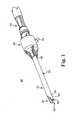
- FIGS. 1 and 2 One embodiment of an intervertebral disc shaving instrument 20 in accordance with principles disclosed herein is shown in FIGS. 1 and 2 .
- the instrument 20 includes an outer tubular assembly 22 and an inner tubular assembly 24.
- the outer tubular assembly 22 includes an outer tubular member 26 and a first hub assembly 28.
- the inner tubular assembly 24 includes an inner tubular member 30 (best seen in FIG. 2 ) and a second hub assembly 32. Details on the various components are provided below.
- the inner tubular member 30 is coaxially disposed within the outer tubular member 26, with the tubular members 26, 30 combining to define a bodily material shaving head 34 ( FIG. 1 ).
- the instrument 20 is coupled to a powered handpiece (not shown) that rotates the second hub assembly 32, and thus the inner tubular member 30, relative to the outer tubular member 26 in an oscillating fashion, to effectuate shearing of intervertebral disc material (not shown) at the shaving head 34.
- a manual decorticating implement 38 is disposed on an outer surface of the outer tubular member 26. The implement 38 is useful to effectuate preparation of end plates (not shown).
- the outer tubular member 26 is an elongated body defining a proximal segment 40 and a distal segment 44 maintaining the implement 38. Further, the outer tubular member 26 defines a central passage 46 ( FIG. 2 ) extending from the distal segment 44 to the proximal segment 40. With specific reference to FIG. 2 , the proximal segment 40 is adapted for connection to the first hub assembly 28, and defines a longitudinal axis A. For example, the proximal segment 40 forms a proximal open end 47 and a radial aperture 48 both of which are open to the central passage 46.
- the open end 47 facilitates placement of the inner tubular member 30 within the central passage 46, whereas the aperture 48 establishes fluid connection between the central passage 46 and a corresponding component of the first hub assembly 28.
- the proximal segment 40 can assume a variety of other forms.
- the outer tubular member 26 can define one or more bends in a region between the proximal segment 40 and the distal segment 44.
- a bend region is disclosed in U.S. Patent Application Publication No. 2007/0149975 A1 .
- inner tubular member 30 conforms to the bend of outer tubular member 26.
- the distal segment 44 terminates at a distal end 52 that is closed to the central passage 46 in one embodiment. Further, the distal segment 44 forms a cutting window 54 proximal the closed distal end 52. As described in greater detail below, the closed distal end 52 serves to distally shield a cutting surface of the inner tubular member 30, whereas the cutting window 54 exposes the surface. Thus, in one embodiment, an exterior surface of the closed distal end 52 is curved.
- the decorticating implement 38 defines a scraping surface provided on an exterior surface of the distal segment 44 and assists a surgeon in preparing end plates for fostering bone growth and adhesion of fusion material.
- the cutting window 54 is open or fluidly connected to the central passage 46, and is defined by a perimeter edge 56.
- the perimeter edge 56 Relative to a longitudinal extension of the outer tubular member 26, the perimeter edge 56 generally defines opposing first and second longitudinal sides 58, 60, and opposing lateral ends 62, 64.
- the perimeter edge 56 forms a plurality of teeth 66 along each of the longitudinal sides 58, 60.
- the teeth 66 can assume a variety of forms, but in one embodiment are symmetrically arranged relative to the side 58, 60.
- each of the sides 58, 60 includes or forms at least four teeth 66 to promote aggressive removal of intervertebral disc material.
- the teeth 66 are formed to be highly sharpened (e.g., tip width or thickness on the order of approximately 0.005 inch (0.0127 mm), and wrap or curve in conformance with a curvature of the remainder of the outer tubular member 26.
- a tip-to-tip spacing between adjacent ones of the teeth 66 (along a corresponding side 58 or 60) is in the range of 0.04-0.06 inch (1.016 - 1.524 mm), more preferably approximately 0.05 inch (0.127 mm) ( ⁇ 0.002 inch (0.0508 mm)).
- the lateral ends 62, 64 are similarly sharp. While other dimensions and/or configurations can be employed, it has surprisingly been found that the above-described preferences are highly conducive to cutting the disparate material structures associated with an intervertebral disc.
- Implement 38 extends from an outer surface of distal segment 44, defining an annular scraping surface 67 formed by a distal surface 68 and a proximal surface 69 of scraping implement 38.
- Distal surface 68 extends generally perpendicular from a circumference of outer tubular member 26, whereas proximal surface 69 is angled toward distal end 52.
- Implement 38, and thus distal surface 68 and/or proximal surface 69 can extend from the outer surface of distal segment 44 at various angles and at various positions with respect to distal segment 44.
- implement 38 (including distal surface 68 and/or proximal surface 69) may extend at an oblique angle with respect to the outer surface of distal segment 44.
- the implement 38 can extend directly from distal end 52, either at an oblique angle with respect thereto or parallel to a direction of extension of the distal segment 44.
- distal surface 68 and proximal surface 69 converge to form scraping surface 67, which is useful in removal of intervertebral disc material from end plates, as discussed below.
- the outer tubular member 26 is preferably formed of a hardened, surgically safe material, capable of supporting the inner tubular member 30 at high rotational/oscillation speeds (e.g., oscillation speed of 5,000 RPM).
- the outer tubular member 26 is formed of 304 stainless steel; although a multitude of other materials are equally acceptable.
- the central passage 46 is sized to coaxially receive the inner tubular member 30 in a manner allowing the inner tubular member 30 to rotate within the passage 46.
- a diameter of the central passage 46 is slightly greater than an outer diameter of the inner tubular member 30 to establish an irrigation pathway.
- the first hub assembly 28 is adapted to receive and retain the proximal segment 40 of the outer tubular member 26, and in one embodiment includes an irrigation collar 68, an outer hub 70, and an inner hub 72.
- the irrigation collar 68 forms an irrigation port 74, and is configured to establish an irrigation fluid flow path to and from the central passage 46 of the outer tubular member 26 upon final assembly, as described below.
- the outer hub 70 and the inner hub 72 are adapted to secure the irrigation collar 68 to the outer tubular member 26, and thus can assume a variety of forms. In one embodiment, however, the outer hub 70 is sized for securement over the irrigation collar 68 as well as to the outer tubular member 26.
- the inner hub 72 is sized for securement between the irrigation collar 68 and the outer tubular member 26, and in one embodiment forms a longitudinal passageway 76 and a radial opening 77.
- the longitudinal passageway 76 extends through an entirety of the inner hub 72, whereas the radial opening 77 is sized and positioned for fluid connection to the port 74 (and the radial aperture 48 of the outer tubular member 26) upon final assembly.
- the first hub assembly 28 further includes seals (e.g., O-rings) 78 and a seal hub 79 in one embodiment.
- the first hub assembly 28 establishes a mechanism for delivering irrigation liquid from an irrigation source (not shown) to the shaving head 34 via the irrigation port 74 and the passage 46.
- the irrigation fluid serves to "clean" the surgical site, augment lubrication between the inner and outer tubular members 30, 26, and facilitate evacuation/aspiration of material from the surgical site (described below) by clearing "clogs" at the shaving head 34.
- the first hub assembly 28 can assume a variety of other forms.
- the inner tubular member 30 is, similar to the outer tubular member 26, an elongated tube defining a proximal region 80 and a distal region 84. Further, the inner tubular member 30 defines a central lumen 86 extending from the proximal region 80 to the distal region 84. Once again, the inner tubular member 30 is sized to be coaxially received within the outer tubular member 26, with the proximal region 80 adapted for mounting to the second hub 32.
- the inner tubular member 30 has an overall construction capable of maintaining structural integrity when rotated at high speeds (e.g., oscillation speeds on the order of 5,000 RPM).
- the distal region 84 forms a cutting tip 90.
- the cutting tip 90 includes a plurality of teeth 92 formed in a circumferentially-extending manner about a mouth 94.
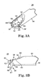
- the teeth 92 are highly similar to the teeth 66 ( FIGS. 3A and 3B ) previously described, symmetrically arranged along opposite sides of the mouth 94 (it being understood that only one set of the teeth 92 are visible in FIG. 3C ).
- at least four of the teeth 92 are formed along each side of the mouth 94, and are highly sharpened.
- the teeth 92 are sized and positioned to be spatially aligned with the teeth 66 upon final assembly.
- adjacent ones of the teeth 92 have a tip-to-tip spacing on the order of 0.04-0.06 inch (1.016 - 1.524 mm), more preferably approximately 0.05 inch (0.127 mm) ( ⁇ 0.002 inch (0.0508 mm)).
- the mouth 94 is open to, and thus fluidly connected with, the lumen 86. As described in greater detail below, this configuration establishes an aspiration pathway from the mouth 94 and through the lumen 86. In this regard, material aspirated via the lumen 86/mouth 94 can be removed via an appropriate port associated with the second assembly hub 32.
- the distal region 84 has a relatively large outer diameter, on the order of 3-8 mm, more preferably 4.5 mm, to reduce clogging of the lumen 86 during use. Alternatively, other dimensions can be employed.
- an inner diameter of the outer tubular member 26 is, in one embodiment, slightly larger than an outer diameter of the inner tubular member 30 so as to establish an annular gap 100 between the two components 26, 30 upon final assembly as shown in FIG. 3D .
- FIG. 3D illustrates the inner tubular member 30 as being approximately centered relative to the outer tubular member 26, in actual practice, the inner tubular member 30 may contact the outer tubular member 26 at various radial locations.
- the cutting tip 90 FIG.
- the inner tubular member 30 may have a diameter larger than a remainder thereof (such as by separately forming the cutting tip 90 and assembling to a remainder of the inner tubular member 30) that more closely matches an inner diameter of the outer tubular member 26.
- a size of the gap 100 is exaggerated in the view of FIG. 3D for purposes of explanation.
- the annular gap 100 extends from the irrigation port 74 to the cutting window 54 to establish an interior irrigation pathway or mechanism by which an irrigation fluid can be delivered from the irrigation port 74 to the cutting window 54 (and thus the shaving head 34) via the annular gap 100.
- a separate irrigation tube (not shown) can be provided along (or formed with) an exterior of the outer tubular member 26.
- the second hub assembly 32 is sized for mounting to the inner tubular member 30 and includes, in one embodiment, a rotating hub 102 and a spring 104.
- the rotating hub 102 is adapted for coupling to a powered handpiece (not shown) as known in the art.
- the spring 104 facilitates releasable engagement with the powered handpiece, and in alternative embodiments, can be eliminated.
- the powered handpiece can assume a variety of forms, and can be electrically, or battery, or pneumatically powered.
- Assembly of the instrument 20 includes securing the first hub assembly 28 to the outer tubular member 26.
- the inner hub 72 is mounted over the proximal segment 40 such that the radial opening 77 is aligned, or otherwise fluidly connected to, the radial aperture 48.
- an adhesive e.g., Loctite adhesive
- the irrigation collar 68 is mounted over the inner hub 72 such that the port 74 is aligned with, or otherwise fluidly connected to, the radial opening 77 (and thus the radial aperture 48).
- the seals 78 are included at opposite sides of the port 74/radial opening 77 interface to provide a fluid-sealed relationship.
- the outer hub 70 is assembled or formed over the outer tubular member 26 and the irrigation collar 68. Where desired, an adhesive (e.g., Loctite adhesive) can be employed to bond the outer hub 70 to the irrigation collar 68.
- the second hub assembly 32 is mounted to the proximal region 80 of the inner tubular member 30.
- An adhesive can be employed to bond the rotating hub 102 to the inner tubular member 30.
- the inner tubular member 30 is distally slid or inserted into and through the inner hub 72 and the outer tubular member 26 such that the cutting tip 90 is at or within the cutting window 54.
- the seal hub 79 sealingly engages an exterior of the inner tubular member 30 such that irrigation fluid within the outer tubular member 26 (e.g., within the gap 100 ( FIG. 3D )) will not flow or leak proximal the seal hub 79.
- the shaving head 34 upon final assembly is shown in greater detail in FIG. 4 .
- the cutting tip 90 is exposed at the cutting window 54.
- a shearing action is created between the teeth 92 of the cutting tip 90 and the teeth 66 of the cutting window 54.
- the closed distal end 52 of the outer tubular member 26 provides a blunt surface for non-traumatically contacting anatomical structures, thus providing instrument safety during "blind” cutting procedures.
- the scraping implement 38 is used in preparation of end plates by a surgeon.
- the implement 38 is brought into contact with an end plate and used to scrape material from the end plate by moving instrument 20 manually with respect to the end plate.
- implement 38 can be scraped to cause bleeding of the end plate, which can provide an adequate surface for adhesion of material deposited thereon.
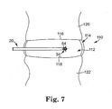
- the intervertebral disc 110 generally includes a nucleus 112 surrounded by an annulus 114 and opposing ends plates 116, 118 ( FIGS. 7 and 8 ).
- the end plates 116, 118 in turn, are formed as part of adjacent vertebrae 120, 122 ( FIGS. 7 and 8 ), respectively, and thus are akin to cartilaginous bone.
- the instrument 20 is employed to surgically remove or shave some or all of the material (e.g., tissue, cartilaginous bone, etc.) associated with the intervertebral disc 110.
- the material e.g., tissue, cartilaginous bone, etc.
- one common procedure associated with treatment of a diseased intervertebral disc 110 is a nucleotomy in which a portion, or all, of the nucleus 112 is removed.
- the instrument 20 is deployed to the disc 110, for example via an posterior-lateral approach.
- Alternative approaches to the disc 110 are also acceptable and within the principles of the present disclosure, such as posterior approach, transforaminal approach, anterior approach, left or right lateral approach, etc. Regardless, as shown in FIG.
- the shaving head 34 is positioned at an exterior of the annulus 114, aligned with an opening 124 formed therein.
- the opening 124 can be a naturally-occurring tear or similar passage; alternatively, the opening 124 can be surgically cut or otherwise created in the annulus 114.
- the closed distal end 52 contacts the annulus 114 in a non-traumatic manner, and protects the annulus 114 from potentially damaging, undesired contact with the teeth 66 ( FIG. 3A ) and 92 ( FIG. 3C ).
- the shaving head 34 is then distally advanced within the annulus 114 and operated to remove some or all of the nucleus 112 region as shown in FIG. 6 .
- the instrument 20 is powered to effectuate removal of contacted material. More particularly, and with additional reference to FIG. 7 , the powered handpiece (not shown) is activated, causing the cutting tip 90 ( FIG. 3C ) to rotationally oscillate relative to the cutting window 54.
- the cutting tip 90 can be rotationally oscillated at speeds at or in excess of 5,000 RPM.
- the powered handpiece is operated to rotate the inner tubular member 26 ( FIG. 2 ) two revolutions in one direction, followed by two revolutions in the opposite direction, etc., although other operational formats are also acceptable.
- Nucleus tissue 112 otherwise in contact with the cutting tip 90/cutting window 54, is sheared between the two components, and aspirated from the surgical site via the mouth 94/lumen 86 ( FIG. 2 ). Further, irrigation fluid is directly applied to the surgical site via the irrigation mechanism previously described so as to minimize clogging of the tissue shaving head 34, and in particular the mouth 94/lumen 86. The irrigation fluid can also serve to lubricate the surgical site as well as the inner tubular member 30/outer tubular member 26 interface.
- end plates 116, 118 can also be scraped as desired using scraping implement 38 without removing instrument 20 from disc 110.
- scraping implement 38 can be positioned to scrape end plate 118.
- Instrument 20, and thus implement 38 can be scraped along end plate 118 in order to prepare the end plate 118 for bone growth and/or adhesion of fusion material.
- a top surface of the end plate 118 can be removed, encouraging blood to enter the end plate 118.
- end plate 118 During an autograft procedure, this blood promotes fusion between the end plate 118 and autograft material introduced in the disc 110. Tissue removed from end plate 118 due to scraping by implement 38 can be aspirated via the mouth 94/lumen 86 by further operation of the instrument 20. End plate 116 can be prepared in a similar manner.
- FIG. 9 illustrates an alternative distal end 200 having a manual scraping implement 202 including annular scraping surfaces 204, 206 and 208.
- the annular surfaces 204, 206 and 208 extend from an outer circumference of outer tubular member 26, and are similar in structure to annular surface 67 discussed above.
- implement 202 is spaced apart from distal end 52 of outer tubular member 26.
- Each of the annular scraping surfaces 204, 206 and 208 are spaced apart from distal end 52 and arranged in parallel fashion to one another.
- implement 202 can include two annular scraping surfaces, wherein one of the surfaces 204, 206 and 208 is eliminated.
- annular scraping surfaces 204, 206 and 208 are not parallel to one another, wherein one or more of the annular scraping surfaces are oblique to the outer surface.
- one of the annular scraping surfaces can form an acute angle with the outer tubular member, whereas another annular scraping surface forms an obtuse angle from a similar reference.
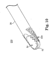
- FIG. 10 illustrates an alternative distal end 220 that includes scraping implement 224 positioned on an outer circumference of outer tubular member 26 on an opposite side of cutting window 54.
- Implement 224 includes a coating that forms a scraping surface to be used in preparation of end plates of an intervertebral disc. In one embodiment, the coating forms irregular protrusions extending from a circumference of the outer tubular member 26.
- the coating of implement 224 in one example, can be formed of a hard biocompatible material such as diamond, nickel coated tungsten and/or combinations thereof.
Claims (9)
- Instrument de rasage de matière d'un disque intervertébral chirurgical à utiliser avec une pièce à main alimentée, l'instrument comportant :un élément tubulaire externe allongé (26) définissant un passage central (46) et une fenêtre de découpe (54) au niveau d'une extrémité distale correspondante, la fenêtre de découpe étant reliée de manière fluide au passage central et définie par un bord de périmètre (56) formant au moins quatre dents (66) sur un premier côté longitudinal (58) et au moins quatre dents (66) sur un second côté longitudinal (60) correspondant,un élément tubulaire interne (30) disposé de manière coaxiale à l'intérieur du passage central, l'élément tubulaire interne définissant une lumière centrale (86) et un embout de découpe (90) au niveau d'une extrémité distale correspondante, l'embout de découpe comprenant une pluralité de dents qui s'étendent de manière circonférentielle (92) formées autour d'au moins une partie d'une bouche (94) reliée sinon de manière fluide à la lumière ;un outil manuel pour décortiquer (38), comprenant une surface de raclage (61), positionnée sur une circonférence externe de l'élément tubulaire externe ; etdans lequel lors de l'assemblage final, l'outil pour décortiquer est configuré pour retirer de la matière d'une plaque d'extrémité, l'embout de découpe est exposé à l'intérieur de la fenêtre de découpe, l'embout de découpe et la fenêtre de découpe combinant pour définir une tête de rasage (34) configurée pour raser de la matière d'un disque intervertébral et aspirer la matière rasée à travers la bouche et la lumière, et caractérisé en ce que l'outil pour décortiquer comprend une surface distale (68) et une surface proximale s'étendant depuis une circonférence externe de l'élément tubulaire externe, la surface distale et la surface proximale définissant la surface de raclage.
- Instrument selon la revendication 1, dans lequel l'outil pour décortiquer est espacé d'une extrémité distale de l'élément tubulaire externe.
- Instrument selon la revendication 1, dans lequel la surface distale est perpendiculaire à un axe de l'élément tubulaire externe.
- Instrument selon la revendication 3, dans lequel la surface proximale est orientée au niveau d'un angle oblique par rapport à la surface distale.
- Instrument selon la revendication 4, dans lequel la surface de raclage est annulaire.
- Instrument selon la revendication 1, dans lequel l'outil comprend une pluralité de surfaces de raclage annulaires (204, 206, 208) qui s'étendent depuis une circonférence externe de l'élément tubulaire externe, la pluralité de surface de raclage annulaires étant espacées les unes des autres le long d'une longueur de l'élément tubulaire externe.
- Instrument selon la revendication 6, dans lequel la pluralité de surfaces de raclage annulaires comprennent trois surfaces de raclage.
- Instrument de rasage de matière d'un disque intervertébral chirurgical à utiliser avec une pièce à main alimentée, l'instrument comportant :un élément tubulaire externe allongé (26) définissant un passage central (46) et une fenêtre de découpe (54) au niveau d'une extrémité distale correspondante, la fenêtre de découpe étant reliée de manière fluide au passage central et définie par un bord de périmètre (56) formant au moins quatre dents (66) sur un premier côté longitudinal (58) et au moins quatre dents (66) sur un second côté longitudinal (60) correspondant,un élément tubulaire interne (30) disposé de manière coaxiale à l'intérieur du passage central, l'élément tubulaire interne définissant une lumière centrale (86) et un embout de découpe (90) au niveau d'une extrémité distale correspondante, l'embout de découpe comprenant une pluralité de dents qui s'étendent de manière circonférentielle (92) formées autour d'au moins une partie d'une bouche (94) reliée sinon de manière fluide à la lumière ;un outil manuel pour décortiquer (38), comprenant une surface de raclage (224) positionnée sur une circonférence externe de l'élément tubulaire externe ; etdans lequel lors de l'assemblage final, l'outil pour décortiquer est configuré pour retirer de la matière d'une plaque d'extrémité, l'embout de découpe est exposé à l'intérieur de la fenêtre de découpe, l'embout de découpe et la fenêtre de découpe combinant pour définir une tête de rasage (34) configurée pour raser de la matière d'un disque intervertébral et aspirer la matière rasée à travers la bouche et la lumière, et caractérisé en ce que la surface de raclage (224) est formée d'un revêtement appliqué sur une surface externe de l'élément tubulaire externe opposé à la fenêtre de découpe.
- Instrument selon la revendication 1, dans lequel le revêtement comporte un diamant.
Applications Claiming Priority (3)
| Application Number | Priority Date | Filing Date | Title |
|---|---|---|---|
| US40579210P | 2010-10-22 | 2010-10-22 | |
| US13/013,384 US8414606B2 (en) | 2010-10-22 | 2011-01-25 | Method and apparatus for removing material from an intervertebral disc space and preparing end plates |
| PCT/US2011/056183 WO2012054302A1 (fr) | 2010-10-22 | 2011-10-13 | Procédé et appareil de retrait d'une matière dans un espace de disque intervertébral, et préparation de plaques d'extrémité |
Publications (2)
| Publication Number | Publication Date |
|---|---|
| EP2629686A1 EP2629686A1 (fr) | 2013-08-28 |
| EP2629686B1 true EP2629686B1 (fr) | 2014-08-20 |
Family
ID=45973605
Family Applications (1)
| Application Number | Title | Priority Date | Filing Date |
|---|---|---|---|
| EP11776959.6A Active EP2629686B1 (fr) | 2010-10-22 | 2011-10-13 | Dispositif de retrait d'une matière d'un espace de disque intervertébral, et pour la préparation des plaques d'extrémité |
Country Status (7)
| Country | Link |
|---|---|
| US (2) | US8414606B2 (fr) |
| EP (1) | EP2629686B1 (fr) |
| JP (1) | JP5997167B2 (fr) |
| CN (1) | CN103298418B (fr) |
| AU (1) | AU2011318377B2 (fr) |
| CA (1) | CA2815136C (fr) |
| WO (1) | WO2012054302A1 (fr) |
Cited By (1)
| Publication number | Priority date | Publication date | Assignee | Title |
|---|---|---|---|---|
| US20150080896A1 (en) | 2013-07-19 | 2015-03-19 | Ouroboros Medical, Inc. | Anti-clogging device for a vacuum-assisted, tissue removal system |
Families Citing this family (35)
| Publication number | Priority date | Publication date | Assignee | Title |
|---|---|---|---|---|
| US20080121343A1 (en) | 2003-12-31 | 2008-05-29 | Microfabrica Inc. | Electrochemical Fabrication Methods Incorporating Dielectric Materials and/or Using Dielectric Substrates |
| US9814484B2 (en) | 2012-11-29 | 2017-11-14 | Microfabrica Inc. | Micro debrider devices and methods of tissue removal |
| US10939934B2 (en) | 2008-06-23 | 2021-03-09 | Microfabrica Inc. | Miniature shredding tools for use in medical applications, methods for making, and procedures for using |
| US9451977B2 (en) | 2008-06-23 | 2016-09-27 | Microfabrica Inc. | MEMS micro debrider devices and methods of tissue removal |
| US8465490B1 (en) * | 2010-01-29 | 2013-06-18 | Greatbatch Ltd. | Disposable neucleotomy shaver |
| US10874552B2 (en) * | 2011-07-08 | 2020-12-29 | Doheny Eye Institute | Ocular lens cutting device |
| US9119659B2 (en) * | 2011-12-03 | 2015-09-01 | Ouroboros Medical, Inc. | Safe cutting heads and systems for fast removal of a target tissue |
| US9827004B2 (en) | 2012-01-31 | 2017-11-28 | Globus Medical, Inc. | Surgical disc removal tool |
| US8585726B2 (en) | 2012-01-31 | 2013-11-19 | Globus Medical, Inc. | Surgical disc removal tool |
| US9603610B2 (en) | 2013-03-15 | 2017-03-28 | DePuy Synthes Products, Inc. | Tools and methods for tissue removal |
| WO2015161061A1 (fr) | 2014-04-17 | 2015-10-22 | Stryker Corporation | Outil chirurgical à arbre sélectivement flexible, qui résiste à la déformation |
| US10667836B2 (en) * | 2014-04-28 | 2020-06-02 | Boston Scientific Scimed, Inc. | Tissue resectors, hand operated tissue resecting systems, and associated methods |
| US9636132B2 (en) * | 2014-09-08 | 2017-05-02 | Medtronic Xomed, Inc. | Tumor debulker |
| US9737322B2 (en) | 2014-09-08 | 2017-08-22 | Medtronic Xomed, Inc. | Method for resection of tumors and tissues |
| US10052128B2 (en) | 2015-08-24 | 2018-08-21 | Qathax, LLC | Catheter extraction |
| AU2015408009B2 (en) * | 2015-08-28 | 2020-09-24 | Avent, Inc. | Liquid delivery method for cooled RF system |
| US9675363B2 (en) | 2015-11-13 | 2017-06-13 | Advance Research System, Llc | Surgical tools having application for spinal surgical procedures and method of use |
| CN109475366B (zh) * | 2016-07-14 | 2021-12-28 | 史赛克欧洲运营有限责任公司 | 具有阻塞减少梢端的外科手术器械的切割组件 |
| EP3531924A1 (fr) * | 2016-10-26 | 2019-09-04 | Michael D. Smith | Dispositif chirurgical portatif ayant une partie rotative |
| CN106562813B (zh) * | 2016-10-28 | 2023-11-28 | 邹德威 | 椎间盘组织一次整体切取,椎间隙成型切割器 |
| WO2019028221A1 (fr) * | 2017-08-02 | 2019-02-07 | Stryker Corporation | Systèmes d'outils chirurgicaux et leurs méthodes d'utilisation |
| CN108852480B (zh) * | 2018-05-21 | 2019-12-10 | 青岛市黄岛区中心医院 | 一种子宫旋切器 |
| CN108577935B (zh) * | 2018-05-21 | 2019-12-24 | 王晓丽 | 一种用于妇科手术的子宫旋切器 |
| CN112243363A (zh) * | 2018-11-05 | 2021-01-19 | 杨宗德 | 一种终板处理器 |
| EP3860477B1 (fr) * | 2018-11-09 | 2024-03-27 | Meditrina, Inc. | Endoscope |
| US11083486B2 (en) | 2019-03-08 | 2021-08-10 | Arthrex, Inc. | Rotary surgical shaver |
| US11324530B2 (en) | 2019-04-22 | 2022-05-10 | Medos International Sarl | Bone and tissue resection devices and methods |
| US11413056B2 (en) | 2019-04-22 | 2022-08-16 | Medos International Sarl | Bone and tissue resection devices and methods |
| US11350948B2 (en) | 2019-04-22 | 2022-06-07 | Medos International Sarl | Bone and tissue resection devices and methods |
| US11389178B2 (en) | 2019-04-22 | 2022-07-19 | Medos International Sarl | Bone and tissue resection devices and methods |
| US11376022B2 (en) | 2019-07-18 | 2022-07-05 | Quadvantage Technology, Inc. | Patella cutting guide |
| CN114469248A (zh) * | 2020-11-14 | 2022-05-13 | 李振宙 | 一种提拉刮刀 |
| US20220370091A1 (en) * | 2021-05-18 | 2022-11-24 | Quadvantage Technology, Inc. | Surgical cutting blade using composite materials |
| KR102418525B1 (ko) * | 2022-02-28 | 2022-07-07 | 주식회사 미랑 | 의료용 절삭기구 |
| CN116763421B (zh) * | 2023-08-18 | 2023-11-24 | 西南石油大学 | 一种具有止血功能的医用刨削刀头 |
Family Cites Families (31)
| Publication number | Priority date | Publication date | Assignee | Title |
|---|---|---|---|---|
| US4203444A (en) | 1977-11-07 | 1980-05-20 | Dyonics, Inc. | Surgical instrument suitable for closed surgery such as of the knee |
| US4573448A (en) | 1983-10-05 | 1986-03-04 | Pilling Co. | Method for decompressing herniated intervertebral discs |
| US5313962A (en) | 1991-10-18 | 1994-05-24 | Obenchain Theodore G | Method of performing laparoscopic lumbar discectomy |
| US5286253A (en) | 1992-10-09 | 1994-02-15 | Linvatec Corporation | Angled rotating surgical instrument |
| US5383884A (en) | 1992-12-04 | 1995-01-24 | American Biomed, Inc. | Spinal disc surgical instrument |
| AU682338B2 (en) | 1993-05-06 | 1997-10-02 | Linvatec Corporation | Rotatable endoscopic shaver with polymeric blades |
| US6095149A (en) | 1996-08-13 | 2000-08-01 | Oratec Interventions, Inc. | Method for treating intervertebral disc degeneration |
| WO1997038635A1 (fr) | 1996-04-12 | 1997-10-23 | Surgical Dynamics, Inc. | Dispositif de coupe chirurgical relie de maniere amovible a un element d'entrainement rotatif |
| US5922003A (en) | 1997-05-09 | 1999-07-13 | Xomed Surgical Products, Inc. | Angled rotary tissue cutting instrument and method of fabricating the same |
| US6217598B1 (en) | 1997-11-25 | 2001-04-17 | Linvatec Corporation | End-cutting shaver blade |
| US5911701A (en) | 1998-01-29 | 1999-06-15 | Sdgi Holidings, Inc. | Surgical cutting instrument |
| US6440138B1 (en) | 1998-04-06 | 2002-08-27 | Kyphon Inc. | Structures and methods for creating cavities in interior body regions |
| US6030401A (en) | 1998-10-07 | 2000-02-29 | Nuvasive, Inc. | Vertebral enplate decorticator and osteophyte resector |
| US6312438B1 (en) | 2000-02-01 | 2001-11-06 | Medtronic Xomed, Inc. | Rotary bur instruments having bur tips with aspiration passages |
| US20030191474A1 (en) | 2000-02-16 | 2003-10-09 | Cragg Andrew H. | Apparatus for performing a discectomy through a trans-sacral axial bore within the vertebrae of the spine |
| US6503263B2 (en) | 2000-09-24 | 2003-01-07 | Medtronic, Inc. | Surgical micro-shaving instrument with elevator tip |
| US20020138091A1 (en) | 2001-03-23 | 2002-09-26 | Devonrex, Inc. | Micro-invasive nucleotomy device and method |
| US7131975B2 (en) | 2002-09-16 | 2006-11-07 | Medtronic Xomed, Inc. | Apparatus and methods for straightening angled tissue cutting instruments |
| US20060200155A1 (en) | 2002-09-27 | 2006-09-07 | Harp Richard J | Surgical file instrument |
| US7976464B2 (en) | 2003-08-26 | 2011-07-12 | Zimmer Spine, Inc. | Access systems and methods for minimally invasive surgery |
| US20050065538A1 (en) | 2003-09-22 | 2005-03-24 | Van Wyk Robert Allen | Asymmetric shaver and methods for making same |
| US7276074B2 (en) | 2004-01-21 | 2007-10-02 | Medtronic Xomed, Inc. | Angled tissue cutting instrument having variably positionable cutting window, indexing tool for use therewith and method of variably positioning a cutting window of an angled tissue cutting instrument |
| US20050209610A1 (en) | 2004-03-03 | 2005-09-22 | Scimed Life Systems, Inc. | Radially adjustable tissue removal device |
| US8562607B2 (en) | 2004-11-19 | 2013-10-22 | Dfine, Inc. | Bone treatment systems and methods |
| US20060196038A1 (en) | 2005-03-02 | 2006-09-07 | Van Wyk Robert A | Arthroscopic shaver with two pass inner blade and method of manufacturing same |
| US8273088B2 (en) | 2005-07-08 | 2012-09-25 | Depuy Spine, Inc. | Bone removal tool |
| ITRE20050098A1 (it) * | 2005-08-05 | 2007-02-06 | Cgm Spa | Strumento chirurgico per raschiare e raccogliere particelle di osso |
| US7927361B2 (en) * | 2005-11-29 | 2011-04-19 | Medtronic Xomed, Inc. | Method and apparatus for removing material from an intervertebral disc space, such as in performing a nucleotomy |
| US20080188877A1 (en) * | 2007-02-05 | 2008-08-07 | Hickingbotham Dyson W | Instruments For Removing an Object From the Eye |
| CN100581489C (zh) * | 2008-08-08 | 2010-01-20 | 浙江大学 | 一套用于胸腰椎前路手术的器械 |
| CN201398985Y (zh) * | 2009-04-13 | 2010-02-10 | 张树立 | 用于椎管减压的骨科铰刀 |
-
2011
- 2011-01-25 US US13/013,384 patent/US8414606B2/en active Active
- 2011-10-13 AU AU2011318377A patent/AU2011318377B2/en active Active
- 2011-10-13 WO PCT/US2011/056183 patent/WO2012054302A1/fr active Application Filing
- 2011-10-13 EP EP11776959.6A patent/EP2629686B1/fr active Active
- 2011-10-13 CA CA2815136A patent/CA2815136C/fr active Active
- 2011-10-13 CN CN201180058713.8A patent/CN103298418B/zh active Active
- 2011-10-13 JP JP2013534955A patent/JP5997167B2/ja active Active
-
2013
- 2013-03-13 US US13/799,233 patent/US9687254B2/en active Active
Cited By (1)
| Publication number | Priority date | Publication date | Assignee | Title |
|---|---|---|---|---|
| US20150080896A1 (en) | 2013-07-19 | 2015-03-19 | Ouroboros Medical, Inc. | Anti-clogging device for a vacuum-assisted, tissue removal system |
Also Published As
| Publication number | Publication date |
|---|---|
| US20130197525A1 (en) | 2013-08-01 |
| CA2815136A1 (fr) | 2012-04-26 |
| EP2629686A1 (fr) | 2013-08-28 |
| JP2013544119A (ja) | 2013-12-12 |
| AU2011318377A1 (en) | 2013-06-13 |
| CN103298418A (zh) | 2013-09-11 |
| AU2011318377B2 (en) | 2016-04-14 |
| US8414606B2 (en) | 2013-04-09 |
| JP5997167B2 (ja) | 2016-09-28 |
| WO2012054302A1 (fr) | 2012-04-26 |
| CN103298418B (zh) | 2016-02-03 |
| US9687254B2 (en) | 2017-06-27 |
| CA2815136C (fr) | 2019-03-05 |
| US20120101513A1 (en) | 2012-04-26 |
Similar Documents
| Publication | Publication Date | Title |
|---|---|---|
| EP2629686B1 (fr) | Dispositif de retrait d'une matière d'un espace de disque intervertébral, et pour la préparation des plaques d'extrémité | |
| US7927361B2 (en) | Method and apparatus for removing material from an intervertebral disc space, such as in performing a nucleotomy | |
| US5383884A (en) | Spinal disc surgical instrument | |
| US9226764B2 (en) | Conformable soft tissue removal instruments | |
| JP4299668B2 (ja) | 手術用リーマのための着脱可能なリーミング・ヘッド | |
| US9826988B2 (en) | Devices and methods for preparing an intervertebral workspace | |
| JP4986553B2 (ja) | 面関節リーマ | |
| EP2564795B1 (fr) | Appareils d'excision de tissus | |
| US20160066946A1 (en) | Discectomy kits with an obturator, guard cannula | |
| EP3021768B1 (fr) | Dispositif anti-obstruction pour un système de retrait de tissu assisté par dépression | |
| US20060224160A1 (en) | Instruments and methods for aggressive yet continuous tissue removal | |
| US20220142656A1 (en) | Device and method for punching bone | |
| US7731719B2 (en) | Safety knife for resection of annulus |
Legal Events
| Date | Code | Title | Description |
|---|---|---|---|
| PUAI | Public reference made under article 153(3) epc to a published international application that has entered the european phase |
Free format text: ORIGINAL CODE: 0009012 |
|
| 17P | Request for examination filed |
Effective date: 20130522 |
|
| AK | Designated contracting states |
Kind code of ref document: A1 Designated state(s): AL AT BE BG CH CY CZ DE DK EE ES FI FR GB GR HR HU IE IS IT LI LT LU LV MC MK MT NL NO PL PT RO RS SE SI SK SM TR |
|
| GRAP | Despatch of communication of intention to grant a patent |
Free format text: ORIGINAL CODE: EPIDOSNIGR1 |
|
| INTG | Intention to grant announced |
Effective date: 20140321 |
|
| GRAS | Grant fee paid |
Free format text: ORIGINAL CODE: EPIDOSNIGR3 |
|
| GRAA | (expected) grant |
Free format text: ORIGINAL CODE: 0009210 |
|
| AK | Designated contracting states |
Kind code of ref document: B1 Designated state(s): AL AT BE BG CH CY CZ DE DK EE ES FI FR GB GR HR HU IE IS IT LI LT LU LV MC MK MT NL NO PL PT RO RS SE SI SK SM TR |
|
| REG | Reference to a national code |
Ref country code: GB Ref legal event code: FG4D |
|
| REG | Reference to a national code |
Ref country code: CH Ref legal event code: EP |
|
| REG | Reference to a national code |
Ref country code: AT Ref legal event code: REF Ref document number: 682974 Country of ref document: AT Kind code of ref document: T Effective date: 20140915 |
|
| REG | Reference to a national code |
Ref country code: IE Ref legal event code: FG4D |
|
| REG | Reference to a national code |
Ref country code: DE Ref legal event code: R096 Ref document number: 602011009349 Country of ref document: DE Effective date: 20141002 |
|
| REG | Reference to a national code |
Ref country code: AT Ref legal event code: MK05 Ref document number: 682974 Country of ref document: AT Kind code of ref document: T Effective date: 20140820 |
|
| REG | Reference to a national code |
Ref country code: NL Ref legal event code: VDEP Effective date: 20140820 |
|
| REG | Reference to a national code |
Ref country code: LT Ref legal event code: MG4D |
|
| PG25 | Lapsed in a contracting state [announced via postgrant information from national office to epo] |
Ref country code: LT Free format text: LAPSE BECAUSE OF FAILURE TO SUBMIT A TRANSLATION OF THE DESCRIPTION OR TO PAY THE FEE WITHIN THE PRESCRIBED TIME-LIMIT Effective date: 20140820 Ref country code: FI Free format text: LAPSE BECAUSE OF FAILURE TO SUBMIT A TRANSLATION OF THE DESCRIPTION OR TO PAY THE FEE WITHIN THE PRESCRIBED TIME-LIMIT Effective date: 20140820 Ref country code: PT Free format text: LAPSE BECAUSE OF FAILURE TO SUBMIT A TRANSLATION OF THE DESCRIPTION OR TO PAY THE FEE WITHIN THE PRESCRIBED TIME-LIMIT Effective date: 20141222 Ref country code: SE Free format text: LAPSE BECAUSE OF FAILURE TO SUBMIT A TRANSLATION OF THE DESCRIPTION OR TO PAY THE FEE WITHIN THE PRESCRIBED TIME-LIMIT Effective date: 20140820 Ref country code: NO Free format text: LAPSE BECAUSE OF FAILURE TO SUBMIT A TRANSLATION OF THE DESCRIPTION OR TO PAY THE FEE WITHIN THE PRESCRIBED TIME-LIMIT Effective date: 20141120 Ref country code: ES Free format text: LAPSE BECAUSE OF FAILURE TO SUBMIT A TRANSLATION OF THE DESCRIPTION OR TO PAY THE FEE WITHIN THE PRESCRIBED TIME-LIMIT Effective date: 20140820 Ref country code: BG Free format text: LAPSE BECAUSE OF FAILURE TO SUBMIT A TRANSLATION OF THE DESCRIPTION OR TO PAY THE FEE WITHIN THE PRESCRIBED TIME-LIMIT Effective date: 20141120 Ref country code: GR Free format text: LAPSE BECAUSE OF FAILURE TO SUBMIT A TRANSLATION OF THE DESCRIPTION OR TO PAY THE FEE WITHIN THE PRESCRIBED TIME-LIMIT Effective date: 20141121 |
|
| PG25 | Lapsed in a contracting state [announced via postgrant information from national office to epo] |
Ref country code: LV Free format text: LAPSE BECAUSE OF FAILURE TO SUBMIT A TRANSLATION OF THE DESCRIPTION OR TO PAY THE FEE WITHIN THE PRESCRIBED TIME-LIMIT Effective date: 20140820 Ref country code: IS Free format text: LAPSE BECAUSE OF FAILURE TO SUBMIT A TRANSLATION OF THE DESCRIPTION OR TO PAY THE FEE WITHIN THE PRESCRIBED TIME-LIMIT Effective date: 20141220 Ref country code: AT Free format text: LAPSE BECAUSE OF FAILURE TO SUBMIT A TRANSLATION OF THE DESCRIPTION OR TO PAY THE FEE WITHIN THE PRESCRIBED TIME-LIMIT Effective date: 20140820 Ref country code: HR Free format text: LAPSE BECAUSE OF FAILURE TO SUBMIT A TRANSLATION OF THE DESCRIPTION OR TO PAY THE FEE WITHIN THE PRESCRIBED TIME-LIMIT Effective date: 20140820 Ref country code: RS Free format text: LAPSE BECAUSE OF FAILURE TO SUBMIT A TRANSLATION OF THE DESCRIPTION OR TO PAY THE FEE WITHIN THE PRESCRIBED TIME-LIMIT Effective date: 20140820 |
|
| PG25 | Lapsed in a contracting state [announced via postgrant information from national office to epo] |
Ref country code: NL Free format text: LAPSE BECAUSE OF FAILURE TO SUBMIT A TRANSLATION OF THE DESCRIPTION OR TO PAY THE FEE WITHIN THE PRESCRIBED TIME-LIMIT Effective date: 20140820 |
|
| PG25 | Lapsed in a contracting state [announced via postgrant information from national office to epo] |
Ref country code: RO Free format text: LAPSE BECAUSE OF FAILURE TO SUBMIT A TRANSLATION OF THE DESCRIPTION OR TO PAY THE FEE WITHIN THE PRESCRIBED TIME-LIMIT Effective date: 20140820 Ref country code: IT Free format text: LAPSE BECAUSE OF FAILURE TO SUBMIT A TRANSLATION OF THE DESCRIPTION OR TO PAY THE FEE WITHIN THE PRESCRIBED TIME-LIMIT Effective date: 20140820 Ref country code: CZ Free format text: LAPSE BECAUSE OF FAILURE TO SUBMIT A TRANSLATION OF THE DESCRIPTION OR TO PAY THE FEE WITHIN THE PRESCRIBED TIME-LIMIT Effective date: 20140820 Ref country code: SK Free format text: LAPSE BECAUSE OF FAILURE TO SUBMIT A TRANSLATION OF THE DESCRIPTION OR TO PAY THE FEE WITHIN THE PRESCRIBED TIME-LIMIT Effective date: 20140820 Ref country code: DK Free format text: LAPSE BECAUSE OF FAILURE TO SUBMIT A TRANSLATION OF THE DESCRIPTION OR TO PAY THE FEE WITHIN THE PRESCRIBED TIME-LIMIT Effective date: 20140820 Ref country code: EE Free format text: LAPSE BECAUSE OF FAILURE TO SUBMIT A TRANSLATION OF THE DESCRIPTION OR TO PAY THE FEE WITHIN THE PRESCRIBED TIME-LIMIT Effective date: 20140820 |
|
| REG | Reference to a national code |
Ref country code: DE Ref legal event code: R097 Ref document number: 602011009349 Country of ref document: DE |
|
| PG25 | Lapsed in a contracting state [announced via postgrant information from national office to epo] |
Ref country code: LU Free format text: LAPSE BECAUSE OF FAILURE TO SUBMIT A TRANSLATION OF THE DESCRIPTION OR TO PAY THE FEE WITHIN THE PRESCRIBED TIME-LIMIT Effective date: 20141013 Ref country code: PL Free format text: LAPSE BECAUSE OF FAILURE TO SUBMIT A TRANSLATION OF THE DESCRIPTION OR TO PAY THE FEE WITHIN THE PRESCRIBED TIME-LIMIT Effective date: 20140820 Ref country code: MC Free format text: LAPSE BECAUSE OF FAILURE TO SUBMIT A TRANSLATION OF THE DESCRIPTION OR TO PAY THE FEE WITHIN THE PRESCRIBED TIME-LIMIT Effective date: 20140820 |
|
| REG | Reference to a national code |
Ref country code: CH Ref legal event code: PL |
|
| PLBE | No opposition filed within time limit |
Free format text: ORIGINAL CODE: 0009261 |
|
| STAA | Information on the status of an ep patent application or granted ep patent |
Free format text: STATUS: NO OPPOSITION FILED WITHIN TIME LIMIT |
|
| PG25 | Lapsed in a contracting state [announced via postgrant information from national office to epo] |
Ref country code: BE Free format text: LAPSE BECAUSE OF NON-PAYMENT OF DUE FEES Effective date: 20141031 |
|
| 26N | No opposition filed |
Effective date: 20150521 |
|
| REG | Reference to a national code |
Ref country code: IE Ref legal event code: MM4A |
|
| PG25 | Lapsed in a contracting state [announced via postgrant information from national office to epo] |
Ref country code: LI Free format text: LAPSE BECAUSE OF NON-PAYMENT OF DUE FEES Effective date: 20141031 Ref country code: CH Free format text: LAPSE BECAUSE OF NON-PAYMENT OF DUE FEES Effective date: 20141031 |
|
| REG | Reference to a national code |
Ref country code: FR Ref legal event code: PLFP Year of fee payment: 5 |
|
| PG25 | Lapsed in a contracting state [announced via postgrant information from national office to epo] |
Ref country code: IE Free format text: LAPSE BECAUSE OF NON-PAYMENT OF DUE FEES Effective date: 20141013 |
|
| PG25 | Lapsed in a contracting state [announced via postgrant information from national office to epo] |
Ref country code: SI Free format text: LAPSE BECAUSE OF FAILURE TO SUBMIT A TRANSLATION OF THE DESCRIPTION OR TO PAY THE FEE WITHIN THE PRESCRIBED TIME-LIMIT Effective date: 20140820 |
|
| PG25 | Lapsed in a contracting state [announced via postgrant information from national office to epo] |
Ref country code: SM Free format text: LAPSE BECAUSE OF FAILURE TO SUBMIT A TRANSLATION OF THE DESCRIPTION OR TO PAY THE FEE WITHIN THE PRESCRIBED TIME-LIMIT Effective date: 20140820 |
|
| GBPC | Gb: european patent ceased through non-payment of renewal fee |
Effective date: 20151013 |
|
| PG25 | Lapsed in a contracting state [announced via postgrant information from national office to epo] |
Ref country code: CY Free format text: LAPSE BECAUSE OF FAILURE TO SUBMIT A TRANSLATION OF THE DESCRIPTION OR TO PAY THE FEE WITHIN THE PRESCRIBED TIME-LIMIT Effective date: 20140820 |
|
| PG25 | Lapsed in a contracting state [announced via postgrant information from national office to epo] |
Ref country code: HU Free format text: LAPSE BECAUSE OF FAILURE TO SUBMIT A TRANSLATION OF THE DESCRIPTION OR TO PAY THE FEE WITHIN THE PRESCRIBED TIME-LIMIT; INVALID AB INITIO Effective date: 20111013 Ref country code: TR Free format text: LAPSE BECAUSE OF FAILURE TO SUBMIT A TRANSLATION OF THE DESCRIPTION OR TO PAY THE FEE WITHIN THE PRESCRIBED TIME-LIMIT Effective date: 20140820 Ref country code: GB Free format text: LAPSE BECAUSE OF NON-PAYMENT OF DUE FEES Effective date: 20151013 Ref country code: BE Free format text: LAPSE BECAUSE OF FAILURE TO SUBMIT A TRANSLATION OF THE DESCRIPTION OR TO PAY THE FEE WITHIN THE PRESCRIBED TIME-LIMIT Effective date: 20140820 Ref country code: MT Free format text: LAPSE BECAUSE OF FAILURE TO SUBMIT A TRANSLATION OF THE DESCRIPTION OR TO PAY THE FEE WITHIN THE PRESCRIBED TIME-LIMIT Effective date: 20140820 |
|
| REG | Reference to a national code |
Ref country code: FR Ref legal event code: PLFP Year of fee payment: 6 |
|
| REG | Reference to a national code |
Ref country code: FR Ref legal event code: PLFP Year of fee payment: 7 |
|
| PG25 | Lapsed in a contracting state [announced via postgrant information from national office to epo] |
Ref country code: MK Free format text: LAPSE BECAUSE OF FAILURE TO SUBMIT A TRANSLATION OF THE DESCRIPTION OR TO PAY THE FEE WITHIN THE PRESCRIBED TIME-LIMIT Effective date: 20140820 |
|
| REG | Reference to a national code |
Ref country code: FR Ref legal event code: PLFP Year of fee payment: 8 |
|
| PG25 | Lapsed in a contracting state [announced via postgrant information from national office to epo] |
Ref country code: AL Free format text: LAPSE BECAUSE OF FAILURE TO SUBMIT A TRANSLATION OF THE DESCRIPTION OR TO PAY THE FEE WITHIN THE PRESCRIBED TIME-LIMIT Effective date: 20140820 |
|
| PGFP | Annual fee paid to national office [announced via postgrant information from national office to epo] |
Ref country code: FR Payment date: 20230920 Year of fee payment: 13 |
|
| PGFP | Annual fee paid to national office [announced via postgrant information from national office to epo] |
Ref country code: DE Payment date: 20230920 Year of fee payment: 13 |