EP3009718B1 - Cartridgeventil - Google Patents
Cartridgeventil Download PDFInfo
- Publication number
- EP3009718B1 EP3009718B1 EP15183099.9A EP15183099A EP3009718B1 EP 3009718 B1 EP3009718 B1 EP 3009718B1 EP 15183099 A EP15183099 A EP 15183099A EP 3009718 B1 EP3009718 B1 EP 3009718B1
- Authority
- EP
- European Patent Office
- Prior art keywords
- frame
- cartridge valve
- valve according
- hydraulic
- elongate hole
- Prior art date
- Legal status (The legal status is an assumption and is not a legal conclusion. Google has not performed a legal analysis and makes no representation as to the accuracy of the status listed.)
- Not-in-force
Links
- 210000002105 tongue Anatomy 0.000 claims description 31
- 229910052751 metal Inorganic materials 0.000 claims description 8
- 239000002184 metal Substances 0.000 claims description 8
- 230000002093 peripheral effect Effects 0.000 claims description 8
- 230000003068 static effect Effects 0.000 claims description 2
- 239000004744 fabric Substances 0.000 description 9
- 239000012530 fluid Substances 0.000 description 5
- 239000000463 material Substances 0.000 description 5
- 238000010276 construction Methods 0.000 description 3
- 239000002245 particle Substances 0.000 description 3
- 229910000831 Steel Inorganic materials 0.000 description 2
- 229910052782 aluminium Inorganic materials 0.000 description 2
- XAGFODPZIPBFFR-UHFFFAOYSA-N aluminium Chemical compound [Al] XAGFODPZIPBFFR-UHFFFAOYSA-N 0.000 description 2
- 238000005336 cracking Methods 0.000 description 2
- 238000007373 indentation Methods 0.000 description 2
- 238000002347 injection Methods 0.000 description 2
- 239000007924 injection Substances 0.000 description 2
- 238000009434 installation Methods 0.000 description 2
- 238000000034 method Methods 0.000 description 2
- 238000003801 milling Methods 0.000 description 2
- 239000007787 solid Substances 0.000 description 2
- 239000010959 steel Substances 0.000 description 2
- 238000003466 welding Methods 0.000 description 2
- 240000006829 Ficus sundaica Species 0.000 description 1
- 239000000853 adhesive Substances 0.000 description 1
- 230000001070 adhesive effect Effects 0.000 description 1
- 230000005540 biological transmission Effects 0.000 description 1
- 230000000295 complement effect Effects 0.000 description 1
- 238000005530 etching Methods 0.000 description 1
- 238000001125 extrusion Methods 0.000 description 1
- 238000001914 filtration Methods 0.000 description 1
- 238000002955 isolation Methods 0.000 description 1
- 238000004519 manufacturing process Methods 0.000 description 1
- 239000000843 powder Substances 0.000 description 1
- 238000003825 pressing Methods 0.000 description 1
- 230000000284 resting effect Effects 0.000 description 1
Images



Classifications
-
- F—MECHANICAL ENGINEERING; LIGHTING; HEATING; WEAPONS; BLASTING
- F16—ENGINEERING ELEMENTS AND UNITS; GENERAL MEASURES FOR PRODUCING AND MAINTAINING EFFECTIVE FUNCTIONING OF MACHINES OR INSTALLATIONS; THERMAL INSULATION IN GENERAL
- F16H—GEARING
- F16H61/00—Control functions within control units of change-speed- or reversing-gearings for conveying rotary motion ; Control of exclusively fluid gearing, friction gearing, gearings with endless flexible members or other particular types of gearing
- F16H61/0003—Arrangement or mounting of elements of the control apparatus, e.g. valve assemblies or snapfittings of valves; Arrangements of the control unit on or in the transmission gearbox
- F16H61/0009—Hydraulic control units for transmission control, e.g. assembly of valve plates or valve units
-
- F—MECHANICAL ENGINEERING; LIGHTING; HEATING; WEAPONS; BLASTING
- F16—ENGINEERING ELEMENTS AND UNITS; GENERAL MEASURES FOR PRODUCING AND MAINTAINING EFFECTIVE FUNCTIONING OF MACHINES OR INSTALLATIONS; THERMAL INSULATION IN GENERAL
- F16K—VALVES; TAPS; COCKS; ACTUATING-FLOATS; DEVICES FOR VENTING OR AERATING
- F16K11/00—Multiple-way valves, e.g. mixing valves; Pipe fittings incorporating such valves
- F16K11/02—Multiple-way valves, e.g. mixing valves; Pipe fittings incorporating such valves with all movable sealing faces moving as one unit
- F16K11/06—Multiple-way valves, e.g. mixing valves; Pipe fittings incorporating such valves with all movable sealing faces moving as one unit comprising only sliding valves, i.e. sliding closure elements
- F16K11/065—Multiple-way valves, e.g. mixing valves; Pipe fittings incorporating such valves with all movable sealing faces moving as one unit comprising only sliding valves, i.e. sliding closure elements with linearly sliding closure members
- F16K11/07—Multiple-way valves, e.g. mixing valves; Pipe fittings incorporating such valves with all movable sealing faces moving as one unit comprising only sliding valves, i.e. sliding closure elements with linearly sliding closure members with cylindrical slides
-
- B—PERFORMING OPERATIONS; TRANSPORTING
- B01—PHYSICAL OR CHEMICAL PROCESSES OR APPARATUS IN GENERAL
- B01D—SEPARATION
- B01D35/00—Filtering devices having features not specifically covered by groups B01D24/00 - B01D33/00, or for applications not specifically covered by groups B01D24/00 - B01D33/00; Auxiliary devices for filtration; Filter housing constructions
-
- B—PERFORMING OPERATIONS; TRANSPORTING
- B01—PHYSICAL OR CHEMICAL PROCESSES OR APPARATUS IN GENERAL
- B01D—SEPARATION
- B01D35/00—Filtering devices having features not specifically covered by groups B01D24/00 - B01D33/00, or for applications not specifically covered by groups B01D24/00 - B01D33/00; Auxiliary devices for filtration; Filter housing constructions
- B01D35/005—Filters specially adapted for use in internal-combustion engine lubrication or fuel systems
-
- F—MECHANICAL ENGINEERING; LIGHTING; HEATING; WEAPONS; BLASTING
- F16—ENGINEERING ELEMENTS AND UNITS; GENERAL MEASURES FOR PRODUCING AND MAINTAINING EFFECTIVE FUNCTIONING OF MACHINES OR INSTALLATIONS; THERMAL INSULATION IN GENERAL
- F16H—GEARING
- F16H61/00—Control functions within control units of change-speed- or reversing-gearings for conveying rotary motion ; Control of exclusively fluid gearing, friction gearing, gearings with endless flexible members or other particular types of gearing
- F16H61/02—Control functions within control units of change-speed- or reversing-gearings for conveying rotary motion ; Control of exclusively fluid gearing, friction gearing, gearings with endless flexible members or other particular types of gearing characterised by the signals used
- F16H61/0262—Control functions within control units of change-speed- or reversing-gearings for conveying rotary motion ; Control of exclusively fluid gearing, friction gearing, gearings with endless flexible members or other particular types of gearing characterised by the signals used the signals being hydraulic
- F16H61/0276—Elements specially adapted for hydraulic control units, e.g. valves
-
- F—MECHANICAL ENGINEERING; LIGHTING; HEATING; WEAPONS; BLASTING
- F16—ENGINEERING ELEMENTS AND UNITS; GENERAL MEASURES FOR PRODUCING AND MAINTAINING EFFECTIVE FUNCTIONING OF MACHINES OR INSTALLATIONS; THERMAL INSULATION IN GENERAL
- F16K—VALVES; TAPS; COCKS; ACTUATING-FLOATS; DEVICES FOR VENTING OR AERATING
- F16K31/00—Actuating devices; Operating means; Releasing devices
- F16K31/02—Actuating devices; Operating means; Releasing devices electric; magnetic
- F16K31/06—Actuating devices; Operating means; Releasing devices electric; magnetic using a magnet, e.g. diaphragm valves, cutting off by means of a liquid
- F16K31/0603—Multiple-way valves
- F16K31/061—Sliding valves
- F16K31/0613—Sliding valves with cylindrical slides
-
- B—PERFORMING OPERATIONS; TRANSPORTING
- B01—PHYSICAL OR CHEMICAL PROCESSES OR APPARATUS IN GENERAL
- B01D—SEPARATION
- B01D2201/00—Details relating to filtering apparatus
- B01D2201/04—Supports for the filtering elements
- B01D2201/0415—Details of supporting structures
-
- B—PERFORMING OPERATIONS; TRANSPORTING
- B01—PHYSICAL OR CHEMICAL PROCESSES OR APPARATUS IN GENERAL
- B01D—SEPARATION
- B01D2201/00—Details relating to filtering apparatus
- B01D2201/04—Supports for the filtering elements
- B01D2201/0415—Details of supporting structures
- B01D2201/0423—Details of supporting structures not in the inner side of the cylindrical filtering elements
-
- B—PERFORMING OPERATIONS; TRANSPORTING
- B01—PHYSICAL OR CHEMICAL PROCESSES OR APPARATUS IN GENERAL
- B01D—SEPARATION
- B01D29/00—Filters with filtering elements stationary during filtration, e.g. pressure or suction filters, not covered by groups B01D24/00 - B01D27/00; Filtering elements therefor
- B01D29/11—Filters with filtering elements stationary during filtration, e.g. pressure or suction filters, not covered by groups B01D24/00 - B01D27/00; Filtering elements therefor with bag, cage, hose, tube, sleeve or like filtering elements
- B01D29/13—Supported filter elements
-
- F—MECHANICAL ENGINEERING; LIGHTING; HEATING; WEAPONS; BLASTING
- F15—FLUID-PRESSURE ACTUATORS; HYDRAULICS OR PNEUMATICS IN GENERAL
- F15B—SYSTEMS ACTING BY MEANS OF FLUIDS IN GENERAL; FLUID-PRESSURE ACTUATORS, e.g. SERVOMOTORS; DETAILS OF FLUID-PRESSURE SYSTEMS, NOT OTHERWISE PROVIDED FOR
- F15B13/00—Details of servomotor systems ; Valves for servomotor systems
- F15B2013/002—Modular valves, i.e. consisting of an assembly of interchangeable components
- F15B2013/004—Cartridge valves
-
- F—MECHANICAL ENGINEERING; LIGHTING; HEATING; WEAPONS; BLASTING
- F16—ENGINEERING ELEMENTS AND UNITS; GENERAL MEASURES FOR PRODUCING AND MAINTAINING EFFECTIVE FUNCTIONING OF MACHINES OR INSTALLATIONS; THERMAL INSULATION IN GENERAL
- F16H—GEARING
- F16H61/00—Control functions within control units of change-speed- or reversing-gearings for conveying rotary motion ; Control of exclusively fluid gearing, friction gearing, gearings with endless flexible members or other particular types of gearing
- F16H2061/0043—Cleaning of hydraulic parts, e.g. removal of an orifice clogging
-
- F—MECHANICAL ENGINEERING; LIGHTING; HEATING; WEAPONS; BLASTING
- F16—ENGINEERING ELEMENTS AND UNITS; GENERAL MEASURES FOR PRODUCING AND MAINTAINING EFFECTIVE FUNCTIONING OF MACHINES OR INSTALLATIONS; THERMAL INSULATION IN GENERAL
- F16K—VALVES; TAPS; COCKS; ACTUATING-FLOATS; DEVICES FOR VENTING OR AERATING
- F16K25/00—Details relating to contact between valve members and seats
- F16K25/005—Particular materials for seats or closure elements
Definitions
- the invention relates to a cartridge valve according to the preamble of patent claim 1.
- a cartridge valve for an automatic transmission which has a hydraulic sleeve having a plurality of connection openings, which is formed as circumferentially extending elongated holes.
- connection openings which is formed as circumferentially extending elongated holes.
- a deeper area is provided in the hydraulic bush where foreign particles such as steel powder sink due to their weight.
- the cartridge valve lends itself to position-based installation, as slots do not completely wrap around the circumference of the hydraulic sleeve so that holes in a cartridge receiving housing can exit directly from the slot.
- the patent DE 10 2011 002 150 A1 already shows a cartridge valve, which has a hydraulic bush, the three ports P, A, B has. These three terminals are formed as oblong holes circumferentially extending with respect to a longitudinal axis of the hydraulic bushing. Sieve inserts are inserted in these slots. The sieve inserts are fixed either in the slot with the aid of hook-shaped holding elements on the sieve insert, or they have a holding band by means of which they are fastened to the hydraulic sleeve.
- a hydraulic valve according to the preamble of claim 1 is known.
- An at least circumferentially trained sieve insert is pushed from an open side of the respective elongated hole in a slot on three sides surrounding, plane groove, so that a bent end of the sieve insert abuts a, formed on the open side of the elongated hole stage of the hydraulic bushing.
- the object of the invention is to provide an alternately formed axially short cartridge valve that is protected from foreign particles.
- the cartridge valve according to the invention is characterized in that the slot provided crescent-shaped and the receiving groove is formed in the region of circumferential ends of the slot as a gap with a height between a recess formed in the receiving groove and a shoulder opposite the shoulder of the receiving groove, wherein the sieve insert a radius the elongated hole adapted bent with its formed on retaining tongues outer edge at least partially positioned between the heel and the top tongue is supported, wherein a thickness of the retaining tabs is smaller than the height of the gap is formed.
- the sieve insert is thus clamped between the heel and the top tongue.
- the slot has an undercut, in which the sieve insert is used.
- the receiving groove in particular in the form of a T-slot, is formed in the region of circumferential ends of the slot.
- the sickle-shaped strainer insert during assembly at its longitudinal ends ends easily, in other words elastically compressed, so that after positioning in the slot, the two ends are arranged in each case after solving the applied voltage between the heel and the top tongue.
- the T-slot is to be inserted into the hydraulic bushing with the aid of a so-called T-slot milling cutter.
- the sieve insert has a frame and a thin sieve received in the frame.
- the frame is generally made of a metal or a plastic and compared to the screen, which is spanned by a hydraulic fluid filtering within the frame, due to its relative to the sieve solid construction pressure and tensile load.
- the frame is set in the slot.
- the advantage is that the sieve is radially freely movable in the slot at a load by the hydraulic fluid, without being exposed due to an alternating load by changing the flow direction and / or inertia of the hydraulic fluid as a result of chafing at edges of the slot damage eg. Cracking. This leads to an improved life of the cartridge valve according to the invention.
- the frame is set in the slot to reduce damage to the screen.
- a retaining tongue is formed in each case. This leads to improved handling of the sieve insert and to a further improved protection of the sieve from damage.
- a shoulder in the slot is provided on the longitudinal sides, on which the sieve insert is placed. This prevents a deflection of the sieve insert during operation of the cartridge valve and thus reduces the risk of cracking and / or breakage of the sieve insert, so that a further improvement in the service life of the cartridge valve is brought about.
- the heel of the receiving groove merges into the heel of the long sides, whereby the heel in the oblong hole is circumferentially closed. This is easy to produce with the help of a milling process.
- the frame is preferably a plastic injection molded part, of which the sieve is extrusion-coated on its peripheral edge 25.
- cartridge valve according to the invention extends from the frame radially outwardly at least one position support web radially outward for securing an axial positioning of the sieve insert in the hydraulic bushing and serves as a positioning aid during assembly.
- At least one clamping tab is formed on the frame, which extends from the frame, starting parallel to the longitudinal axis.
- each receiving groove is formed on the longitudinal sides thereof.
- the clamping strap can be completely along the frame longitudinal axis formed complementary to the longitudinal axis of the slot. However, it is the secured bracket the sieve insert sufficient sections provided on the frame longitudinal axis clamping plates.
- the hydraulic bushing of the cartridge valve can be installed in a receiving housing in a position-oriented manner. This allows an axially very short construction, when several with respect to a longitudinal axis of the hydraulic bush axially successive slots are circumferentially offset from one another.
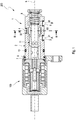
- Fig. 1 shows an electromagnetic cartridge valve 200 with a hydraulic member 1.
- This hydraulic member 1 comprises a hydraulic bushing 2 with circumferentially aligned oblong holes, a first slot 3, a second slot 4 and a third slot 5.
- These three slots 3, 4, 5 are arranged axially successively with respect to a longitudinal axis 6 of the hydraulic sleeve 2.
- the hydraulic bushing 2 has an annular projection 7 at its end, which is close to an electromagnetic actuator 100, and extends radially outward. At the other end, the hydraulic bush 2 is reduced by means of a housing paragraph 8 in diameter.
- the former end has on the annular projection 7 a circumferential annular groove 9. Between this annular projection 7 and the oblong holes 3, 4, 5, a circumferential further annular groove 10 is provided, into which an O-ring is inserted, which seals the connections to the outside to a housing, not shown.
- One connection is a supply connection P, which is arranged axially centrally between two working connections A, B with respect to the longitudinal axis 6. These two working ports A, B are arranged with respect to the longitudinal axis 6 on the supply port P opposite side of the hydraulic bushing 2.
- the supply port P is used to supply the hydraulic part 1 with a hydraulic fluid.
- the two working ports A, B are hydraulically connectable with chambers of a hydraulically controlled device, for example a Schwenkmotorversteller a camshaft.
- the positioning of an axially movably received in the hydraulic sleeve 2 piston 11 corresponding to the working ports A, B are either locked, fully or partially released, by means of the piston 11 the slots 3, 4, 5 associated, formed in the hydraulic bushing 2 channels, a the first slot 3 associated first channel 31, a second slot 4 associated second channel 32 and the third slot 5 associated third channel 33, correspondingly blocked for exposure to the hydraulic fluid to be fully or partially released.
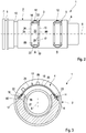
- Fig. 2 the hydraulic bush 2 is shown in a view of the two working ports A, B.
- first slot 3 and the third slot 5 each one identical to the sieve insert 12 of the second slot 4 sieve insert 12 is arranged. Since the sieve inserts 12 of the three slots 3, 4, 5, and the three slots 3, 4, 5 are identical, only a sieve insert or a slot will be explained in detail below.
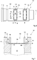
- Fig. 3 shows the hydraulic bush 2 in a section along the section line III-III, as shown in Fig. 1 is drawn.
- the section runs through the sieve insert 12, which is inserted into the second slot 4 of the supply connection P.
- the sieve inserts 12 in the slots 3, 5 of the two working ports A, B are used.
- the sieve insert 12 comprises a closed circumferential frame 15 made of plastic.
- the frame 15 has a rectangular shape, rounded corner edges having basic geometry, which is bent due to the sleeve shape of the hydraulic bushing 2 a radius in the region of the slot 4 of the hydraulic bush 2 adapted.
- the frame 15 of the frame 15 receives the bend only after inserting the sieve insert 12 in the hydraulic bushing 2 or even in the production of the frame 15th
- the sieve insert 12 is placed captive in the slot 4, the slot 4 has a receiving groove 16, in which the frame 15 is received.
- the frame 15 is inserted into the receiving groove 16, and lies on the one hand on the inner edge 17 of the slot 4, on the other hand it lies between a shoulder 18 of the slot 4 and the receiving groove 16 and is supported, in particular with an outer edge 90 at one the shoulder 18 radially opposite cover tongue 19 of the receiving groove 16 from.
- the receiving groove 16 is formed in the present first embodiment only in the region of the arcuate ends of the slot 4. Likewise, it could be formed over the entire circumference of the second slot 4, that is to say also on longitudinal sides 24 of the slot 4.
- a thin screen 20 is arranged, which was inserted during the injection process of the frame 15 in the mold.
- the wire 20 is designed in this embodiment as a screen fabric.
- the sieve 20 as described below as an etched or stamped thin sheet metal.
- the screen 20 is encapsulated at the peripheral edge 25 of the plastic of the frame 15.
- a first retaining tongue 22 and a second retaining tongue 23 are provided, which are arranged between the shoulder 18 and the cover tongue 19.
- Fig. 4 shows in a perspective view of the hydraulic bushing 2 of the first embodiment without Siebhub 12.
- Fig. 5 shows the sieve insert 12 of the first embodiment in a perspective view.
- position holding webs 89 are formed at the periphery of the frame 15 .
- the position retaining webs 89 are arranged at regular intervals on the longitudinal sides of the frame 15 and the frame longitudinal sides 26 and serve for axial positioning of the sieve insert 12 during operation of the cartridge valve 200 and have a simple rectangular cross section.
- the positioning webs 89 are remote from the piston 11 in the hydraulic bush 2, thus positioned facing the corresponding port.
- Fig. 6 shows a hydraulic member 101 of a second embodiment of the cartridge valve 200.
- This hydraulic member 101 differs primarily by the execution of the three Siebein accounts 112 of the hydraulic member 1, which will be discussed below only on the strainer insert 112 and the slot 103 of the working port A, da the three sieve inserts 112 and the elongated holes 103, 104, 105 are of identical construction.
- the sieve insert 112 consists of a sieve 120, which is mounted in a frame 115 made of metal.
- the screen 120 is in this case again designed as a screen fabric, but can also be advantageously provided as etched or stamped sheet as described below.
- the first slot 103 of Hydraulic sleeve 102 is inserted, wherein the retaining tabs 22, 23 is inserted into a formed between the shoulder 118 and the top tongue 19 gap 21.
- the frame 115 has on its longitudinal frame sides 26, the position support webs 189 and also relative to the position support webs 189 axially offset clamping plates 30, wherein the clamping plates 30 are arranged on the outer edge 190 of the frame 115.
- the clamping straps 30 do not extend completely in their longitudinal extent L1 over the circumference of the strainer insert 112, but extend only in sections over this, which is sufficient for fixing and thus for holding the sieve insert 112 in the hydraulic bushing 102.
- the first slot 103 has the receiving groove 16 not only in the region of its ends for clamping the first retaining tongue 22 and the second retaining tongue 23, but also along its longitudinal sides 24.
- the Siebmony 112 is resting with a lower surface 196 of the frame 115 on the shoulder 118 and arranged with its outer edge 190 clamped in the receiving groove 16, wherein a positive connection between the frame 115 and the receiving groove 16 is formed.
- the frame 115 is clamped at its outer edge 190 of the sieve insert 112.
- the shoulder 118 in the region of the longitudinal side 24 does not necessarily have to correspond in its dimensioning to the shoulder 118 in the region of the ends of the first slot 103.
- Fig. 8 a section of the hydraulic member 101 in the region of the first elongated hole 103 for detailed view of the strainer insert 112 in the first slot 103 is shown, wherein the strainer 112 in Fig. 10 is shown in a perspective view.
- an inner edge 117 of the elongated hole 103 is formed in a circumferential surface of the hydraulic bushing 102 varying distance, wherein in the region of the receiving groove 16 for receiving the retaining tongues 22, 23 a largest distance is formed.
- Fig. 11 shows a third embodiment.
- the hydraulic member 201 differs primarily by the execution of the three identical Siebein accounts or the identical slots 203, 204, 205, of which again only a strainer 212 and a slot 203 is explained in more detail.
- FIGs 12 and 15 show a perspective view of the Siebdonatinges 212 of the third embodiment.
- the straining insert 212 is shown in a section along the longitudinal axis 6.
- Fig. 14 shows the trained for receiving the Siebein accounts 212 hydraulic bushing 202 in a perspective view.
- the frame 215 of the sieve insert 212 has on its side facing the longitudinal sides 24 also formed clamping plates 30 which are clamped in the, in this embodiment also over the entire circumference extending receiving groove 16 of the first elongated hole 203, wherein the clamping plates 30 at the outer edge 290 of the frame 215 are arranged.
- the clamping straps 30 do not extend completely in their longitudinal extent L1 over the circumference of the strainer insert 212, but extend only in sections over the frame longitudinal sides 26, which is sufficient for fixing and thus for holding the strainer insert 212 in the hydraulic bushing 202.
- the sieve insert 212 is disposed with a lower surface 296 of the frame 215 on the shoulder 218 and clamped with its outer edge 290 in the receiving groove 16, wherein a positive connection between the frame 215 and the receiving groove 16 is formed.
- the retaining tongues 22, 23 are accommodated in the respective end region of the first elongated hole 203 for further secure positioning of the sieve insert 212 in the first elongated hole 203 in the receiving groove 16 formed therein, wherein in these end regions the first elongated hole 203 has the covering tongue 19 opposite the shoulder 218.
- the frame 215 is inserted into the receiving groove 16, and rests against the inner edge 217 of the first elongated hole 203, wherein it rests on the shoulder 218 of the first elongated hole 203 and is supported on a paragraph 218 radially opposite top tongue 219 of the receiving groove 16.
- a thickness D of the holding tongues 22, 23 chosen so large that a formed between the top tongue 19 and the shoulder 18 and 118 and 218 gap 21 has just as large gap height H, that the retaining tabs 22, 23 with Help a static friction positively between the top tongue and the paragraph 18 or 118 and 218 are fixed.
- the frame 15, 115, 215, like the sieve 20, 120, 220, may be formed from a metal, in particular a steel or an aluminum, preferably corresponding to the material of the hydraulic sleeve 2, 102, 202.
- the sieve insert 12, 112, 212 may additionally be fixed to the corresponding slot with the aid of a material connection, in particular welded connection. If the frame 15, 115, 215 is formed from a plastic, an adhesive is to be preferred.
- the screen 20, 120, 220 can be both a metallic fabric and a plastic fabric.
- a plastic fabric has a corresponding mesh size.
- the sieve 20, 120, 220 formed of a sheet metal is more robust in comparison to a wire or sieve fabric, so that damage due to high volume flows, which impinge on the sieve 20, 120, 220 with the appropriate pressure and corresponding speed, can be excluded.
- screen openings are made by etching, they can be selectively displayed and optimized according to the specific functional requirements of the respective valves.
- the sieve insert 12 has an integrally formed with the frame 15 sieve 20.
- the screen 20 in the form of a screen fabric has a peripheral edge in the form of the frame, which is solidified by pressing so far that the screen fabric can not open, i. in other words is not permeable at the edge as in the rest of the sieve insert 12.
- the frame 15 corresponds to this trained edge.
- Such an edge-consolidated screen cloth 20 is also referred to as a solid metal screen.
- the sieve insert 12 is inserted into the first slot 3 of the hydraulic bush 2. Subsequently, the edge 15 of the sieve insert 12 is welded directly to the hydraulic bushing 2.
- the material pairing of the hydraulic bush 2 and the sieve insert 12 must be selected according to the weldability. In particular, similar material is weldable.
- both the hydraulic bushing 2 and the sieve insert 12 may be made of aluminum.
- the sieve insert 12 can be welded onto the shoulder 18 in the oblong hole 3 at various circumferential points, the welding points preferably being distributed uniformly around the circumference of the edge 15. However, it is also possible, the welding points voltage optimized or optimized with respect to the tightness welded to the hydraulic sleeve 2.
- the cartridge valve 200 has a check valve 93, s. Fig.1 , which is arranged together with the sieve insert 12 in the second slot 4.
- these can be arranged together with a check valve 93 in a corresponding channel 31, 32, 33.
- the described embodiments are only exemplary embodiments. Further, in particular not described features of the device parts belonging to the invention, are to take the geometries of the device parts shown in the drawings.
Landscapes
- Engineering & Computer Science (AREA)
- General Engineering & Computer Science (AREA)
- Mechanical Engineering (AREA)
- Chemical & Material Sciences (AREA)
- Chemical Kinetics & Catalysis (AREA)
- Combustion & Propulsion (AREA)
- Valve Housings (AREA)
- Filtration Of Liquid (AREA)
Description
- Die Erfindung betrifft ein Cartridgeventil gemäß dem Oberbegriff von Patentanspruch 1.
- Aus der Patentschrift
US 5 247 965 ist ein Cartridgeventil für ein Automatikgetriebe bekannt, das eine Hydraulikbuchse aufweist, die mehrere Anschlussöffnungen aufweist, welche als sich in Umfangsrichtung begrenzt erstreckende Langlöcher ausgeformt ist. Um zu verhindern, dass Fremdpartikel das Cartridgeventil festklemmen lassen, ist ein tieferer Bereich in der Hydraulikbuchse vorgesehen, an dem Fremdpartikel - wie Stahlpulver - aufgrund ihres Gewichts absinken. Das Cartridgeventil bietet sich für den lageorientierten Einbau an, da Langlöcher nicht gänzlich um den Umfang der Hydraulikbuchse umlaufen, so dass Bohrungen in einem das Cartridgeventil aufnehmenden Gehäuse direkt von dem Langloch abgehen können. - Aus der Patentschrift
DE 195 10 647 C1 ist ein weiteres Cartridgeventil bekannt. Dieses Cartridgeventil weist zwei Versorgungsanschlüsse P, einen Arbeitsanschluss A und einen Tankanschluss T auf. In die Versorgungsanschlüsse P und den Arbeitsanschluss A sind jeweils Einsätze eingesetzt. - Die Patentschrift
DE 10 2011 002 150 A1 zeigt bereits ein Cartridgeventil, das eine Hydraulikbuchse aufweist, die drei Anschlüsse P, A, B aufweist. Diese drei Anschlüsse sind als sich bezüglich einer Längsachse der Hydraulikbuchse in Umfangsrichtung begrenzt erstreckende Langlöcher ausgeformt. In diese Langlöcher sind Siebeinsätze eingesetzt. Die Siebeinsätze sind dabei entweder mit Hilfe vom am Siebeinsatz hakenförmig ausgebildeten Halteelemente im Langloch fixiert oder sie weisen ein Halteband auf, mittels dessen sie an der Hydraulikbuchse befestigt sind. - Aus der
US 2008/0230452 A1 ist ein Hydraulikventil gemäß dem Oberbegriff des Patentanspruchs 1 bekannt. Ein wenigstens am Umfang plan ausgebildeter Siebeinsatz wird von einer offenen Seite des jeweiligen Langloches in eine das Langloch an drei Seiten umgebende, plane Nut geschoben, so dass ein gebogenes Ende des Siebeinsatzes an einer, an der offenen Seite des Langloches ausgebildeten Stufe der Hydraulikbuchse anliegt. - Aufgabe der Erfindung ist es, ein alternativ ausgebildetes axial kurzes Cartridgeventil zu schaffen, dass vor Fremdpartikeln geschützt ist.
- Diese Aufgabe wird erfindungsgemäß mit den Merkmalen von Patentanspruch 1 gelöst.
- Das erfindungsgemäße Cartridgeventil zeichnet sich dadurch aus, dass das Langloch sichelförmig vorgesehen und die Aufnahmenut im Bereich von Umfangsenden des Langlochs als Spalt mit einer Höhe zwischen einem in der Aufnahmenut ausgebildeten Absatz und einer dem Absatz gegenüberliegenden Deckzunge der Aufnahmenut ausgebildet ist, wobei der Siebeinsatz einem Radius des Langloches angepasst gebogen mit seiner an Haltezungen ausgebildeten Außenkante zumindest teilweise zwischen dem Absatz und der Deckzunge sich abstützend positionierbar ist, wobei eine Dicke der Haltzungen kleiner als die Höhe des Spaltes ausgebildet ist. Der Siebeinsatz ist somit zwischen dem Absatz und der Deckzunge einklemmbar. Mit anderen Worten weist das Langloch einen Hinterschnitt auf, in welchen der Siebeinsatz eingesetzt wird. Der Vorteil ist ein einfacher Einbau des Siebeinsatzes in der Hydraulikbuchse.
- Vorteilhafterweise ist die Aufnahmenut, insbesondere in Form einer T-Nut, im Bereich von Umfangsenden des Langlochs ausgebildet ist. Dabei kann der sichelförmig ausgebildete Siebeinsatz während der Montage an seinen Längsenden Enden leicht, mit anderen Worten elastisch zusammengedrückt werden, so dass nach einer Positionierung im Langloch die beiden Enden jeweils, nach Lösung der aufgebrachten Spannung, zwischen dem Absatz und der Deckzunge angeordnet sind. Die T-Nut ist mit Hilfe eines so genannten T-Nut-Fräsers in die Hydraulikbuchse einzubringen.
- In einer vorteilhaften Ausgestaltung weist der Siebeinsatz einen Rahmen und ein im Rahmen aufgenommenes dünnes Sieb auf. Der Vorteil besteht darin, dass der Rahmen im Allgemeinen aus einem Metall oder einem Kunststoff hergestellt wird und im Vergleich zum Sieb, welches ein Hydraulikfluid filternd innerhalb des Rahmens aufgespannt ist, aufgrund seiner relativ zum Sieb massiven Bauweise druck- und zugbelastbar ist.
- Damit eine Schädigung des Siebes im Langloch vermieden wird, ist der Rahmen im Langloch festgelegt. Der Vorteil ist, dass das Sieb im Langloch bei einer Belastung durch das Hydraulikfluid radial frei bewegbar ist, ohne aufgrund einer Wechselbelastung durch eine Änderung der Strömungsrichtung und/oder Massenkraft des Hydraulikfluids infolge eines Scheuern an Kanten des Langlochs Schädigungen bspw. Rissbildungen ausgesetzt zu sein. Dies führt zu einer verbesserten Lebensdauer des erfindungsgemäßen Cartridgeventils. Mit anderen Worten ist der Rahmen im Langloch festgelegt zur Reduzierung einer Schädigung des Siebes.
- An Umfangsenden des Langlochs zugewandt positionierbare Rahmenenden des Rahmens ist jeweils eine Haltezunge ausgebildet. Dies führt zu einer verbesserten Handhabung des Siebeinsatzes und zu einem weiteren verbesserten Schutz des Siebes vor einer Schädigung.
- In einer weiteren verbesserten Ausgestaltung ist ein Absatz im Langloch an dessen Längsseiten vorgesehen, auf den der Siebeinsatz aufgesetzt ist. Dies verhindert eine Durchbiegung des Siebeinsatzes im Betrieb des Cartridgeventils und vermindert somit eine Riss- und/oder Bruchgefahr des Siebeinsatzes, so dass eine weitere Verbesserung der Lebensdauer des Cartridgeventils herbeigeführt ist.
- Der Absatz der Aufnahmenut geht in den Absatz der Längsseiten über, wobei der Absatz im Langloch umlaufend geschlossen ist. Dies ist einfach herstellbar mit Hilfe eines Fräsverfahrens.
- Der Rahmen ist bevorzugt ein Kunststoffspritzgussteil, von welchem das Sieb an seiner Umfangskante 25 umspritzt ist. Somit ist aufgrund einer einfachen Umspritzkontur des Siebes vorteilhaft ein einfaches Siebeinsatzdesign realisierbar.
- In einer weiteren Ausgestaltung des erfindungsgemäßen Cartridgeventils erstreckt sich vom Rahmen radial nach außen zumindest ein Positionshalterungssteg radial nach außen zur Sicherung einer axialen Positionierung des Siebeinsatzes in der Hydraulikbuchse und dient als Positionierhilfe während der Montage.
- Zur weiteren gesicherten Fixierung des Siebeinsatzes im Langloch ist zumindest eine Klemmlasche am Rahmen ausgebildet, welche sich vom Rahmen ausgehend parallel zur Längsachse erstreckt. Zur Aufnahme der Klemmlasche im Langloch ist an dessen Längsseiten jeweils die Aufnahmenut ausgebildet. Die Klemmlasche kann dabei vollständig entlang der komplementär zur Längsachse des Langlochs ausgebildeten Rahmenlängsachse sein. Allerdings ist es zur gesicherten Halterung des Siebeinsatzes ausreichend abschnittsweise an der Rahmenlängsachse Klemmlaschen vorzusehen.
- In besonders vorteilhafter Weise kann dabei die Hydraulikbuchse des Cartridgeventils in einem aufnehmenden Gehäuse lageorientiert eingebaut sein. Das ermöglicht eine axial sehr kurze Bauweise, wenn mehrere bezüglich einer Längsachse der Hydraulikbuchse axial aufeinander folgende Langlöcher im Umfang versetzt zueinander angeordnet sind.
- Weitere Vorteile, Merkmale und Einzelheiten der Erfindung ergeben sich aus der nachfolgenden Beschreibung bevorzugter Ausführungsbeispiele sowie anhand der Zeichnung. Die vorstehend in der Beschreibung genannten Merkmale und Merkmalskombinationen sowie die nachfolgend in der Figurenbeschreibung genannten und/oder in den Figuren alleine gezeigten Merkmale und Merkmalskombinationen sind nicht nur in der jeweils angegebenen Kombination, sondern auch in anderen Kombinationen oder in Alleinstellung verwendbar, ohne den Rahmen der Erfindung zu verlassen. Gleichen oder funktionsgleichen Elementen sind identische Bezugszeichen zugeordnet. Aus Gründen der Übersichtlichkeit ist es möglich, dass die Elemente nicht in allen Figuren mit ihrem Bezugszeichen versehen sind, ohne jedoch ihre Zuordnung zu verlieren. Es zeigen:
-
Fig. 1 in einer geschnittenen Darstellung ein elektromagnetisches Hydraulikventil mit einer Hydraulikbuchse, -
Fig. 2 eine Hydraulikbuchse in einer Sicht auf zwei Arbeitsanschlüsse mit je einem Siebeinsatz eines elektromagnetischen Hydraulikventils in einem ersten Ausführungsbeispiel, -
Fig. 3 in einem Schnitt entlang der Schnittlinie III-III die Hydraulikbuchse des Hydraulikventils gem.Fig. 1 , -
Fig. 4 in einer perspektivischen Ansicht die Hydraulikbuchse des Hydraulikventils gem.Fig. 2 ohne Siebeinsatz, -
Fig. 5 in einer perspektivischen Ansicht der Siebeinsatz des Hydraulikventils gem.Fig. 2 , -
Fig. 6 in einer Unteransicht die Hydraulikbuchse eines elektromagnetischen Hydraulikventils in einer zweiten Ausführungsform, -
Fig. 7 in einem Längsschnitt ein Ausschnitt der Hydraulikbuchse im Bereich des Siebeinsatzes des Hydraulikventils gem.Fig. 6 , -
Fig. 8 in einer Detailansicht der Siebeinsatz der Hydraulikbuchse des Hydraulikventils gem.Fig. 6 , -
Fig. 9 in einer perspektivischen Ansicht die Hydraulikbuchse ohne Siebeinsatz des Hydraulikventils gem.Fig. 6 , -
Fig. 10 in einer perspektivischen Ansicht der Siebeinsatz des Hydraulikventils gem.Fig. 6 , -
Fig. 11 in einer Unteransicht die Hydraulikbuchse eines elektromagnetischen Hydraulikventils in einer dritten Ausführungsform, -
Fig. 12 in einer Detailansicht der Siebeinsatz des Hydraulikventils gem.Fig. 11 , -
Fig. 13 in einem Längsschnitt ein Ausschnitt der Hydraulikbuchse im Bereich des Siebeinsatzes des Hydraulikventils gem.Fig. 11 , -
Fig. 14 in einer perspektivischen Ansicht die Hydraulikbuchse ohne Siebeinsatz des Hydraulikventils gem.Fig. 11 , und -
Fig. 15 in einer perspektivischen Ansicht der Siebeinsatz des Hydraulikventils gem.Fig. 11 . -
Fig. 1 zeigt ein elektromagnetisches Cartridgeventil 200 mit einem Hydraulikglied 1. Dieses Hydraulikglied 1 umfasst eine Hydraulikbuchse 2 mit umfangsmäßig ausgerichteten Langlöchern, einem ersten Langloch 3, einem zweiten Langloch 4 und einem dritten Langloch 5. Diese drei Langlöcher 3, 4, 5 sind bezüglich einer Längsachse 6 der Hydraulikbuchse 2 axial aufeinanderfolgend angeordnet. Die Hydraulikbuchse 2 weist dabei an ihrem einem elektromagnetischen Stellglied 100 nahe stehenden Ende einen ringförmigen Ansatz 7 auf, der sich radial nach außen erstreckt. An dem anderen Ende ist die Hydraulikbuchse 2 mittels eines Gehäuseabsatzes 8 im Durchmesser verringert. Das erstgenannte Ende weist am ringförmigen Ansatz 7 eine umlaufende Ringnut 9 auf. Zwischen diesem ringförmigen Ansatz 7 und den Langlöchern 3, 4, 5 ist eine umlaufende weitere Ringnut 10 vorgesehen, in die ein O-Ring eingesetzt ist, der Anschlüsse nach außen hin zu einem nicht näher dargestellten Gehäuse abdichtet. - Ein Anschluss ist ein Versorgungsanschluss P, der bezüglich der Längsachse 6 axial mittig zwischen zwei Arbeitsanschlüssen A, B angeordnet ist. Diese beiden Arbeitsanschlüsse A, B sind bezüglich der Längsache 6 auf der dem Versorgungsanschluss P gegenüber liegenden Seite der Hydraulikbuchse 2 angeordnet.
- Der Versorgungsanschluss P dient der Versorgung des Hydraulikteils 1 mit einem Hydraulikfluid. Die beiden Arbeitsanschlüsse A, B sind mit Kammern einer hydraulikgesteuerten Vorrichtung, bspw. einen Schwenkmotorversteller einer Nockenwelle hydraulisch verbindbar. Der Positionierung eines in der Hydraulikbuchse 2 axial bewegbar aufgenommenen Kolbens 11 entsprechend, sind die Arbeitsanschlüsse A, B entweder gesperrt, vollständig oder teilweise freigegeben, wobei mittels des Kolbens 11 den Langlöchern 3, 4, 5 zugeordnete, in der Hydraulikbuchse 2 ausgebildete Kanäle, ein dem ersten Langloch 3 zugeordneter erster Kanal 31, ein dem zweiten Langloch 4 zugeordneter zweiter Kanal 32 und ein dem dritten Langloch 5 zugeordneter dritter Kanal 33, zur Beaufschlagung mit dem Hydraulikfluid entsprechend gesperrt, vollständig oder teilweise freigegeben werden.
- In
Fig. 2 ist die Hydraulikbuchse 2 in einer Sicht auf die beiden Arbeitsanschlüsse A, B dargestellt. Im ersten Langloch 3 und im dritten Langloch 5 ist jeweils ein mit dem Siebeinsatz 12 des zweiten Langlochs 4 baugleicher Siebeinsatz 12 angeordnet. Da die Siebeinsätze 12 der drei Langlöcher 3, 4, 5, sowie die drei Langlöcher 3, 4, 5 baugleich sind, wird im Folgenden nur ein Siebeinsatz bzw. ein Langloch detailliert erläutert. -
Fig. 3 zeigt die Hydraulikbuchse 2 in einem Schnitt entlang der Schnittlinie III-III, wie sie inFig. 1 eingezeichnet ist. Der Schnitt verläuft dabei durch den Siebeinsatz 12, welcher in das zweite Langloch 4 des Versorgungsanschlusses P eingesetzt ist. In gleicher Weise sind die Siebeinsätze 12 in den Langlöchern 3, 5 der beiden Arbeitsanschlüsse A, B eingesetzt. - Der Siebeinsatz 12 umfasst einen geschlossen umlaufenden Rahmen 15 aus Kunststoff. Der Rahmen 15 weist eine rechteckformartige, abgerundete Eckkanten aufweisende Grundgeometrie auf, welche aufgrund der Hülsenform des Hydraulikbuchse 2 einem Radius im Bereich des Langlochs 4 der Hydraulikbuchse 2 angepasst gebogen ist. Je nach gewähltem Material des Rahmens 15 erhält der Rahmen 15 die Biegung erst nach einem Einlegen des Siebeinsatzes 12 in die Hydraulikbuchse 2 oder bereits bei der Herstellung des Rahmens 15.
- Damit der Siebeinsatz 12 im Langloch 4 unverlierbar platziert ist, weist das Langloch 4 eine Aufnahmenut 16 auf, in die der Rahmen 15 aufgenommen ist. Der Rahmen 15 ist in die Aufnahmenut 16 eingefügt, und liegt zum einen an der Innenkante 17 des Langlochs 4, zum anderen liegt er zwischen einem Absatz 18 des Langlochs 4 bzw. der Aufnahmenut 16 auf und stützt sich, insbesondere mit einer Außenkante 90 an einer dem Absatz 18 radial gegenüberliegende Deckzunge 19 der Aufnahmenut 16 ab.
- Die Aufnahmenut 16 ist im vorliegenden ersten Ausführungsbeispiel nur im Bereich der bogenförmig ausgebildeten Enden des Langlochs 4 ausgebildet. Ebenso könnte sie über den vollständigen Umfang des zweiten Langlochs 4, also auch an Längsseiten 24 des Langlochs 4 ausgebildet sein.
- Innerhalb des Rahmens 15 ist ein dünnes Sieb 20 angeordnet, welches beim Spritzvorgang des Rahmens 15 in die Form eingelegt wurde. Das Sieb 20 ist in diesem Ausführungsbeispiel als Siebgewebe ausgeführt. Alternativ kann das Sieb 20 wie nachstehend beschrieben als ein geätztes oder gestanztes dünnes Blech ausgeführt sein.
- Das Sieb 20 ist an dessen Umfangskante 25 vom Kunststoff des Rahmens 15 umspritzt. An den beiden Enden des jeweiligen Siebeinsatzes 12 sind Haltezungen, eine erste Haltezunge 22 und eine zweite Haltezunge 23, vorgesehen, die zwischen dem Absatz 18 und der Deckzunge 19 angeordnet sind.
-
Fig. 4 zeigt in einer perspektivischen Ansicht die Hydraulikbuchse 2 des ersten Ausführungsbeispiels ohne Siebeinsatz 12. Die Enden des Langlochs 4, in die die Haltezungen 22, 23 angeordnet sind, weisen jeweils Einbuchtungen 28 auf, die einer Positionierung des Siebeinsatzes 12 in der Montage des Cartridgeventils 200 dienen. -
Fig. 5 zeigt den Siebeinsatz 12 des ersten Ausführungsbeispiels in einer perspektivischen Ansicht. Am Umfang des Rahmens 15 sind Positionshalterungsstege 89 ausgebildet. Die Positionshalterungsstege 89 sind an den Längsseiten des Rahmens 15 bzw. den Rahmenlängsseiten 26 in regelmäßigen Abständen angeordnet und dienen einer axialen Positionierung des Siebeinsatzes 12 im Betrieb des Cartridgeventils 200 und weisen einen einfachen rechteckförmigen Querschnitt auf. Die Positionierungsstege 89 sind in der Hydraulikbuchse 2 vom Kolben 11 abgewandt, somit dem entsprechenden Anschluss zugewandt positioniert. -
Fig. 6 zeigt ein Hydraulikglied 101 einer zweiten Ausführungsform des Cartridgeventils 200. Dieses Hydraulikglied 101 unterscheidet sich vorrangig durch die Ausführung der drei Siebeinsätze 112 von dem Hydraulikglied 1, von denen im Folgenden nur auf den Siebeinsatz 112 bzw. das Langloch 103 des Arbeitsanschlusses A eingegangen wird, da die drei Siebeinsätze 112 bzw. die Langlöcher 103, 104, 105 baugleich ausgeführt sind. Der Siebeinsatz 112 besteht aus einem Sieb 120, welches in einen Rahmen 115 aus Metall montiert ist. - Das Sieb 120 ist in diesem Fall wieder als Siebgewebe ausgeführt, kann jedoch wie nachstehend beschrieben auch vorteilhafterweise als geätztes oder gestanztes Blech vorgesehen sein. Im Montageprozess des Cartridgeventils 200 wird der Siebeinsatz 112 vorgebogen, in das entsprechende Langloch, hier das erste Langloch 103 der Hydraulikbuchse 102 eingesetzt, wobei die Haltezungen 22, 23 in ein zwischen dem Absatz 118 und der Deckzunge 19 ausgebildeten Spalt 21 gesteckt wird.
- Der Rahmen 115 weist an seinen Rahmenlängsseiten 26 die Positionshalterungsstege 189 und auch relativ zu den Positionshalterungsstegen 189 axial versetzte Klemmlaschen 30 auf, wobei die Klemmlaschen 30 an der Außenkante 190 des Rahmens 115 angeordnet sind. Die Klemmlaschen 30 erstrecken sich in ihrer Längsausdehnung L1 nicht vollständig über den Umfang des Siebeinsatzes 112, sondern erstrecken sich nur abschnittsweise über diesen, was zur Fixierung und somit zur Halterung des Siebeinsatzes 112 in der Hydraulikbuchse 102 ausreichend ist.
- Das erste Langloch 103 weist die Aufnahmenut 16 nicht nur im Bereich ihrer Enden zum Verklemmen der ersten Haltezunge 22 und der zweiten Haltezunge 23 auf, sondern auch entlang ihrer Längsseiten 24. Der Siebeinsatz 112 ist mit einer Unterfläche 196 des Rahmens 115 auf dem Absatz 118 aufliegend und mit seiner Außenkante 190 in die Aufnahmenut 16 eingeklemmt angeordnet, wobei eine formschlüssige Verbindung zwischen dem Rahmen 115 und der Aufnahmenut 16 ausgebildet ist. Mit anderen Worten ist in diesem Ausführungsbeispiel der Rahmen 115 an seiner Außenkante 190 des Siebeinsatzes 112 eingeklemmt. Der Absatz 118 im Bereich der Längsseite 24 muss in seiner Dimensionierung nicht zwingend mit dem Absatz 118 im Bereich der Enden des ersten Langlochs 103 übereinstimmen.
- In
Fig. 8 ist ein Ausschnitt des Hydraulikgliedes 101 im Bereich des ersten Langlochs 103 zur detaillierten Ansicht des Siebeinsatzes 112 im ersten Langloch 103 dargestellt, wobei der Siebeinsatz 112 inFig. 10 in einer perspektivischen Darstellung gezeigt ist. -
Fig. 9 zeigt die Hydraulikbuchse 102 des zweiten Ausführungsbeispiels ohne Siebeinsatz 112. Im Vergleich zur Hydraulikbuchse 2 des ersten Ausführungsbeispiels ist eine Innenkante 117 des Langlochs 103 in einem zur Mantelfläche der Hydraulikbuchse 102 variierenden Abstand ausgebildet, wobei im Bereich der Aufnahmenut 16 zur Aufnahme der Haltezungen 22, 23 ein größter Abstand ausgebildet ist. -
Fig. 11 zeigt eine dritte Ausführungsform. Das Hydraulikglied 201 unterscheidet sich vorrangig durch die Ausführung der drei identischen Siebeinsätze bzw. der identischen Langlöcher 203, 204, 205, von denen wieder nur ein Siebeinsatz 212 bzw. ein Langloch 203 näher erläutert wird. - Die
Figuren 12 und15 zeigen eine perspektivische Ansicht des Siebeinsatzes 212 der dritten Ausführungsform. InFig. 13 ist der Siebeinsatz 212 in einem Schnitt entlang der Längsachse 6 dargestellt.Fig. 14 zeigt die zur Aufnahme der Siebeinsätze 212 ausgebildete Hydraulikbuchse 202 in einer perspektivischen Ansicht. - Der Rahmen 215 des Siebeinsatzes 212 weist an seinen den Längsseiten 24 zugewandt ausgebildeten Seiten ebenfalls Klemmlaschen 30 auf, welche in der, in diesem Ausführungsbeispiel ebenfalls über den gesamten Umfang sich erstreckende Aufnahmenut 16 des ersten Langlochs 203 eingeklemmt sind, wobei die Klemmlaschen 30 an der Außenkante 290 des Rahmens 215 angeordnet sind. Die Klemmlaschen 30 erstrecken sich in ihrer Längsausdehnung L1 nicht vollständig über den Umfang des Siebeinsatzes 212, sondern erstrecken sich nur abschnittsweise über die Rahmenlängsseiten 26, was zur Fixierung und somit zur Halterung des Siebeinsatzes 212 in der Hydraulikbuchse 202 ausreichend ist.
- Der Siebeinsatz 212 ist mit einer Unterfläche 296 des Rahmens 215 auf dem Absatz 218 aufliegend und mit seiner Außenkante 290 in die Aufnahmenut 16 eingeklemmt angeordnet, wobei eine formschlüssige Verbindung zwischen dem Rahmen 215 und der Aufnahmenut 16 ausgebildet ist. Die Haltezungen 22, 23 werden im jeweiligen Endbereich des ersten Langlochs 203 zur weiteren gesicherten Positionierung des Siebeinsatzes 212 im ersten Langloch 203 in der dort ausgebildeten Aufnahmenut 16 aufgenommen ist, wobei in diesen Endbereichen das erste Langloch 203 die dem Absatz 218 gegenüberliegende Deckzunge 19 aufweist. Somit ist der Rahmen 215 in die Aufnahmenut 16 eingefügt, und liegt an der Innenkante 217 des ersten Langlochs 203 an, wobei er auf dem Absatz 218 des ersten Langlochs 203 aufliegt und sich an einer dem Absatz 218 radial gegenüberliegende Deckzunge 219 der Aufnahmenut 16 abstützt.
- In allen Ausführungsbeispielen ist eine Dicke D der Haltezungen 22, 23 so groß gewählt, dass ein zwischen der Deckzunge 19 und dem Absatz 18 bzw. 118 bzw. 218 ausgebildeter Spalt 21 eine gerade so große Spalthöhe H aufweist, dass die Haltezungen 22, 23 mit Hilfe einer Haftreibung formschlüssig zwischen der Deckzunge und dem Absatz 18 bzw. 118 bzw. 218 fixiert sind.
- Der Rahmen 15, 115, 215 kann wie auch das Sieb 20, 120, 220 aus einem Metall, insbesondere ein Stahl oder ein Aluminium, bevorzugt korrespondierend zum Material der Hydraulikbuchse 2, 102, 202 ausgebildet sein. Ebenso kann der Siebeinsatz 12, 112, 212 zusätzlich am entsprechenden Langloch mit Hilfe einer stoffschlüssigen Verbindung, insbesondere Schweißverbindung fixiert sein. Sofern der Rahmen 15, 115, 215 aus einem Kunststoff ausgebildet ist, ist ein Klebemittel zu bevorzugen.
- Das Sieb 20, 120, 220 kann sowohl ein metallisches Gewebe als auch ein Kunststoffgewebe sein. Ein Kunststoffgewebe hat dabei eine entsprechende Maschenweite.
- Um ein besonders robustes Sieb 20, 120, 220 zu erhalten, ist es ferner vorteilhafterweise denkbar, das Sieb 20, 120, 220 als ein geätztes oder gestanztes dünnes Blech auszuführen.
- Das aus einem Blech ausgebildete Sieb 20, 120, 220 ist im Vergleich zu einem Draht- oder Siebgewebe robuster, so dass Beschädigungen durch hohe Volumenströme, welche mit entsprechendem Druck und entsprechender Geschwindigkeit auf das Sieb 20, 120, 220 auftreffen, ausgeschlossen werden können. Wenn Sieböffnungen durch Ätzen hergestellt werden, können diese entsprechend den speziellen Funktionsanforderungen der jeweiligen Ventile gezielt dargestellt und optimiert werden. So ist es beispielsweise denkbar, die Sieböffnungen als Blenden auszubilden, so dass ein temperaturunabhängiger und gezielter Druckabfall bei der Durchströmung des Siebes 20, 120, 220 erzielt werden kann.
- In einem weiteren nicht näher dargestellten Ausführungsbeispiel weist der Siebeinsatz 12 ein einstückig mit dem Rahmen 15 ausgebildetes Sieb 20 auf. Das Sieb 20 in Form eines Siebgewebes besitzt einen umlaufenden Rand in Form des Rahmens, welcher durch Pressen soweit verfestigt ist, dass sich das Siebgewebe nicht Öffnen kann, d.h. mit anderen Worten am Rand nicht durchlässig ist wie im übrigen Bereich des Siebeinsatzes 12. Der Rahmen 15 entspricht diesem ausgebildeten Rand.
- Ein solches am Rand verfestigtes Siebgewebe 20 wird auch als Vollmetallsieb bezeichnet. Der Siebeinsatz 12 wird in das erste Langloch 3 der Hydraulikbuchse 2 eingelegt. Im Anschluss wird der Rand 15 des Siebeinsatzes 12 direkt an der Hydraulikbuchse 2 angeschweißt. Die Materialpaarung von der Hydraulikbuchse 2 und dem Siebeinsatz 12 muss entsprechend der Schweißbarkeit ausgewählt werden. Insbesondere ist gleichartiges Material schweißbar. Beispielsweise kann sowohl die Hydraulikbuchse 2 als auch der Siebeinsatz 12 aus Aluminium gefertigt sein.
- Der Siebeinsatz 12 kann an verschiedenen umfangsmäßigen Stellen auf dem Absatz 18 im Langloch 3 angeschweißt werden, wobei die Schweißpunkte bevorzugt gleichmäßig am Umfang des Randes 15 verteilt sind. Es ist jedoch auch möglich, die Schweißpunkte spannungsoptimiert oder hinsichtlich der Dichtheit optimiert an der Hydraulikbuchse 2 anzuschweißen.
- Das erfindungsgemäße Cartridgeventil 200 weist ein Rückschlagventil 93 auf, s.
Fig.1 , welches gemeinsam mit dem Siebeinsatz 12 im zweiten Langloch 4 angeordnet ist. Mit anderen Worten können unabhängig auf den unterschiedlich ausgebildeten Siebeinsätzen 12, 112, 212 diese gemeinsam mit einem Rückschlagventil 93 in einem entsprechenden Kanal 31, 32, 33 angeordnet sein. Bei den beschriebenen Ausführungsformen handelt es sich nur um beispielhafte Ausgestaltungen. Weitere, insbesondere nicht beschriebene Merkmale der zur Erfindung gehörenden Vorrichtungsteile, sind den in den Zeichnungen dargestellten Geometrien der Vorrichtungsteile zu entnehmen. -
- 1, 101, 201
- Hydraulikglied
- 2, 102, 202
- Hydraulikbuchse
- 3, 103, 203
- erstes Langloch
- 4, 104, 204
- zweites Langloch
- 5, 105, 205
- drittes Langloch
- 6
- Längsachse
- 7
- Ansatz
- 8
- Gehäuseabsatz
- 9
- Ringnut
- 10
- weitere Ringnut
- 11
- Kolben
- 12, 112, 212
- Siebeinsatz
- 15, 115, 215
- Rahmen
- 16
- Aufnahmenut
- 17, 117, 217
- Innenkante
- 18, 118, 218
- Absatz
- 19
- Deckzunge
- 20, 120, 220
- dünnes Sieb
- 21
- Spalt
- 22
- erste Haltezunge
- 23
- zweite Haltezunge
- 24
- Längsseite
- 25
- Umfangskante
- 26
- Rahmenlängsseite
- 28
- Einbuchtung
- 30
- Klemmlasche
- 31
- erster Kanal
- 32
- zweiter Kanal
- 33
- dritter Kanal
- 89, 189, 289
- Positionshalterungssteg
- 90, 190, 290
- Außenkante
- 91
- Innenlängskante
- 92
- Ausnehmung
- 93
- Rückschlagventil
- 96, 196, 296
- Innenseite / Unterfläche
- 100
- Stellglied
- 200
- Cartridgeventil
- A
- Arbeitsanschluss
- B
- Hydraulikanschluss
- D
- Dicke
- L1
- Längsausdehnung (115)
- P
- Hydraulikanschluss
Claims (12)
- Cartridgeventil, das eine Hydraulikbuchse (2; 102; 202) aufweist, die zumindest einen Anschluss (P bzw. A bzw. B) aufweist, welcher als sich bezüglich einer Längsachse (6) der Hydraulikbuchse (2; 102; 202) in Umfangsrichtung begrenzt erstreckendes Langloch (3, 103, 203; 4, 104, 204; 5, 105, 205) ausgeformt ist und welcher mittels eines in das Langloch (3, 103, 203; 4, 104, 204; 5, 105, 205) eingesetzten Siebeinsatzes (12; 112; 212) geschützt ist, wobei das Langloch (3, 103, 203; 4, 104, 204; 5, 105, 205) eine zumindest teilweise über den Umfang des Langlochs (3, 103, 203; 4, 104, 204; 5, 105, 205) ausgebildete Aufnahmenut (16) aufweist, dadurch gekennzeichnet, dass das Langloch (3, 103, 203; 4, 104, 204; 5, 105, 205) sichelförmig vorgesehen und die Aufnahmenut (16) jeweils im Bereich von Umfangsenden des Langlochs (3, 103, 203; 4, 104, 204; 5, 105, 205) als Spalt (21) mit einer Höhe (H) zwischen einem in der Aufnahmenut (16) ausgebildeten Absatz (18; 118; 218) und einer dem Absatz (18; 118; 218) gegenüberliegenden Deckzunge (19) der Aufnahmenut (16) ausgebildet ist, wobei der Siebeinsatz (12; 112; 212) einem Radius des Langloches (3, 103, 203; 4, 104, 204; 5, 105, 205) angepasst gebogen mit seiner an umfänglich endseitigen Haltezungen (22, 23) ausgebildeten Außenkante (90; 190; 290) zumindest teilweise zwischen dem Absatz (18; 118; 218) und der Deckzunge (19) sich abstützend positionierbar ist, wobei eine Dicke (D) der Haltezungen (22, 23) kleiner als die Höhe (H) des Spaltes (21) ausgebildet ist, so dass die Haltezungen (22, 23) mit Hilfe einer Haftreibung formschlüssig zwischen der Deckzunge (19) und dem Absatz (18; 118; 218) fixiert sind.
- Cartridgeventil nach Patentanspruch 1,
dadurch gekennzeichnet, dass
die Aufnahmenut (16) als T-Nut ausgeführt ist. - Cartridgeventil nach einem der vorhergehenden Patentansprüche,
dadurch gekennzeichnet, dass
der Siebeinsatz (12; 112; 212) einen Rahmen (15; 115; 215) und ein im Rahmen aufgenommenes dünnes Sieb (20; 120; 220) aufweist. - Cartridgeventil nach Patentanspruch 3,
dadurch gekennzeichnet, dass
der Rahmen (15; 115; 215) im Langloch (3, 103, 203; 4, 104, 204; 5 105, 205) festgelegt ist. - Cartridgeventil nach einem der Patentansprüche 3 oder 4,
dadurch gekennzeichnet, dass
der Rahmen (15; 115; 215) an seinen den Umfangsenden des Langlochs (3, 103, 203; 4, 104, 204; 5 105, 205) zugewandt positionierbaren Rahmenenden jeweils die Haltezunge (22, 23) aufweist. - Cartridgeventil nach einem der Patentansprüche 3 bis 5,
dadurch gekennzeichnet, dass
das Sieb als geätztes oder gestanztes Blech ausgebildet ist. - Cartridgeventil nach einem der vorhergehenden Patentansprüche,
dadurch gekennzeichnet, dass
der Absatz (18; 118; 218) zusätzlich an Längsseiten (24) des Langlochs (3, 103, 203; 4, 104, 204; 5 105, 205) vorgesehen ist, auf den der Siebeinsatz (12; 112; 212) aufgesetzt ist. - Cartridgeventil nach einem der vorherigen Patentansprüche,
dadurch gekennzeichnet, dass
der Absatz (18; 118; 218) geschlossen umlaufend ist. - Cartridgeventil nach einem der Patentansprüche 3 bis 8, dadurch gekennzeichnet, dass
der Rahmen (15; 115; 215) ein Kunststoffspritzgussteil ist, von welchem das Sieb (20; 120; 220) an dessen Außenkante (90; 190; 290) umspritzt ist. - Cartridgeventil nach einem der Patentansprüche 3 bis 9,
dadurch gekennzeichnet, dass
sich vom Rahmen (15; 115) zumindest ein Positionshalterungssteg (89; 189) radial nach außen erstreckt. - Cartridgeventil nach einem der Patentansprüche 3 bis 9,
dadurch gekennzeichnet, dass
sich vom Rahmen (115; 215) zumindest eine Klemmlasche (30) parallel zur Längsachse (6) erstreckt. - Cartridgeventil nach einem der vorhergehenden Patentansprüche,
dadurch gekennzeichnet, dass
mehrere bezüglich der Längsachse (6) der Hydraulikbuchse (2; 102; 202) axial aufeinander folgende Langlöcher (3, 4, 5; 103, 104, 105; 203, 204, 205) im Umfang der Hydraulikbuchse (2; 102; 202) versetzt zueinander angeordnet sind.
Applications Claiming Priority (1)
| Application Number | Priority Date | Filing Date | Title |
|---|---|---|---|
| DE102014114880.0A DE102014114880A1 (de) | 2014-10-14 | 2014-10-14 | Cartridgeventil |
Publications (2)
| Publication Number | Publication Date |
|---|---|
| EP3009718A1 EP3009718A1 (de) | 2016-04-20 |
| EP3009718B1 true EP3009718B1 (de) | 2018-08-08 |
Family
ID=54014622
Family Applications (1)
| Application Number | Title | Priority Date | Filing Date |
|---|---|---|---|
| EP15183099.9A Not-in-force EP3009718B1 (de) | 2014-10-14 | 2015-08-31 | Cartridgeventil |
Country Status (4)
| Country | Link |
|---|---|
| US (1) | US9933077B2 (de) |
| EP (1) | EP3009718B1 (de) |
| CN (1) | CN105508589B (de) |
| DE (1) | DE102014114880A1 (de) |
Families Citing this family (4)
| Publication number | Priority date | Publication date | Assignee | Title |
|---|---|---|---|---|
| DE102012223430A1 (de) * | 2012-12-17 | 2014-06-18 | Robert Bosch Gmbh | Elektromagnetisches Stellglied |
| US20170356562A1 (en) * | 2016-06-10 | 2017-12-14 | Husco Automotive Holdings Inc. | Systems and methods for filter orientation on a control valve |
| DE102019101115A1 (de) * | 2018-02-21 | 2019-08-22 | ECO Holding 1 GmbH | Hydraulikventil für einen Schwenkmotorversteller einer Nockenwelle |
| USD912625S1 (en) * | 2018-05-31 | 2021-03-09 | Transportation Ip Holdings, Llc | Oil filter housing |
Family Cites Families (18)
| Publication number | Priority date | Publication date | Assignee | Title |
|---|---|---|---|---|
| US1534129A (en) * | 1923-06-13 | 1925-04-21 | Neptune Meter Co | Sand trap and strainer |
| JP2898082B2 (ja) | 1990-11-05 | 1999-05-31 | アイシン・エィ・ダブリュ株式会社 | リニヤソレノイドバルブ装置 |
| DE19510647C1 (de) | 1995-03-23 | 1996-02-22 | Bosch Gmbh Robert | Elektromagnetisch betätigbares Druckregelventil und Verfahren zu dessen Herstellung |
| DE10144289B4 (de) * | 2001-09-08 | 2007-03-22 | Hydraulik Ring Gmbh | Ventil |
| JP4172211B2 (ja) * | 2002-06-06 | 2008-10-29 | 株式会社デンソー | 流量制御装置 |
| JP4400486B2 (ja) * | 2005-03-16 | 2010-01-20 | アイシン・エィ・ダブリュ株式会社 | 制御弁 |
| JP2008232272A (ja) * | 2007-03-20 | 2008-10-02 | Denso Corp | スプール弁 |
| JP4900074B2 (ja) * | 2007-06-18 | 2012-03-21 | アイシン・エィ・ダブリュ株式会社 | 電磁弁 |
| US8186378B2 (en) * | 2008-04-15 | 2012-05-29 | Husco Automotive Holdings, LLC | Filter band for an electrohydraulic valve |
| KR101168505B1 (ko) * | 2008-05-29 | 2012-07-30 | 아이신에이더블류 가부시키가이샤 | 전자기 밸브 장치 |
| JP5130132B2 (ja) * | 2008-06-30 | 2013-01-30 | 株式会社三栄水栓製作所 | 湯水混合栓用のサーモカートリッジ |
| US8127790B2 (en) * | 2009-03-25 | 2012-03-06 | Husco Automotive Holdings Llc | Hydraulic valve with a filter and check valve band |
| DE102010011834A1 (de) * | 2010-03-18 | 2011-09-22 | Schaeffler Technologies Gmbh & Co. Kg | Filterelement und Steuerventil für ein Nockenwellenverstellsystem |
| DE102011002150B4 (de) | 2011-04-19 | 2013-01-17 | Hydraulik-Ring Gmbh | Cartridgeventil |
| JP2013050166A (ja) * | 2011-08-31 | 2013-03-14 | Denso Corp | 流体制御弁 |
| US8656948B2 (en) * | 2011-09-13 | 2014-02-25 | Husco Automotive Holdings Llc | Hydraulic valve with an annular filter element secured by a helical spring |
| JP6022814B2 (ja) * | 2012-06-08 | 2016-11-09 | 株式会社ミクニ | 制御弁用フィルタおよび制御弁の挿入構造 |
| JP5935611B2 (ja) * | 2012-09-11 | 2016-06-15 | 株式会社デンソー | 制御弁 |
-
2014
- 2014-10-14 DE DE102014114880.0A patent/DE102014114880A1/de not_active Ceased
-
2015
- 2015-08-17 US US14/827,481 patent/US9933077B2/en not_active Expired - Fee Related
- 2015-08-31 EP EP15183099.9A patent/EP3009718B1/de not_active Not-in-force
- 2015-09-11 CN CN201510578173.6A patent/CN105508589B/zh not_active Expired - Fee Related
Non-Patent Citations (1)
| Title |
|---|
| None * |
Also Published As
| Publication number | Publication date |
|---|---|
| DE102014114880A1 (de) | 2016-04-14 |
| US9933077B2 (en) | 2018-04-03 |
| CN105508589A (zh) | 2016-04-20 |
| EP3009718A1 (de) | 2016-04-20 |
| US20160102755A1 (en) | 2016-04-14 |
| CN105508589B (zh) | 2018-08-31 |
Similar Documents
| Publication | Publication Date | Title |
|---|---|---|
| DE102010026853B4 (de) | Steuerventil zur Steuerung von Druckmittelströmen eines Nockenwellenverstellers | |
| EP2927439B1 (de) | Hydraulikventil für einen Schwenkmotorversteller einer Nockenwelle | |
| EP2929210B1 (de) | Stossdämpfer für ein fahrzeug mit einem flansch zur verbindung eines externen modulrohres | |
| DE102016207779B4 (de) | Spannvorrichtung für einen Kettentrieb | |
| EP2154339A1 (de) | Ölwanne mit Öfilter an Trägereinheit | |
| DE102014015946A1 (de) | Kühlkanalabdeckung sowie mit einer Kühlkanalabdeckung versehener Kolben | |
| EP3009718A1 (de) | Cartridgeventil | |
| DE102010011834A1 (de) | Filterelement und Steuerventil für ein Nockenwellenverstellsystem | |
| DE102019133669A1 (de) | Vorrichtung mit einem Bauteil und einem Ventilgehäuse | |
| WO2021018341A1 (de) | Ventil und vorrichtung zur regelung von drücken eines strömungsmittels mit dem ventil sowie vorrichtung zur sicherung des ventils in dem getriebebauteil | |
| EP2855943B1 (de) | Geberzylinder | |
| EP3601865B1 (de) | Rohrkupplung | |
| DE102015105489A1 (de) | Aktor | |
| DE102012110570A1 (de) | Buchse für ein hydraulisches Kolbenventil, hydraulisches Kolbenventil und Nockenwellenversteller | |
| DE102011002150B4 (de) | Cartridgeventil | |
| DE29709021U1 (de) | Rückschlagventil | |
| WO2024121344A1 (de) | Druckausgleichsvorrichtung für ein gehäuse | |
| DE102012202312A1 (de) | Fluidbefüllbares Elastomerlager | |
| EP3115662B1 (de) | Hydraulikventil, insbesondere cartridgeventil | |
| EP2481474A1 (de) | Dichtungsanordnung für stabförmige keramische Filterelemente | |
| DE102016008501B4 (de) | Mikrofilter zum Filtern von flüssigen oder gasförmigen Medien | |
| DE10137296B4 (de) | Halteelement zur Festlegung eines Maschinenteils | |
| DE102016102221B4 (de) | Hydraulikventil | |
| DE102012218664B4 (de) | Steuerventil für eine hydraulische Vorrichtung mit einem Filterblech | |
| DE102019120227A1 (de) | Ventil und Vorrichtung zur Regelung von Drücken eines Strömungsmittels mit dem Ventil sowie Vorrichtung zur Sicherung des Ventils in dem Getriebebauteil |
Legal Events
| Date | Code | Title | Description |
|---|---|---|---|
| PUAI | Public reference made under article 153(3) epc to a published international application that has entered the european phase |
Free format text: ORIGINAL CODE: 0009012 |
|
| AK | Designated contracting states |
Kind code of ref document: A1 Designated state(s): AL AT BE BG CH CY CZ DE DK EE ES FI FR GB GR HR HU IE IS IT LI LT LU LV MC MK MT NL NO PL PT RO RS SE SI SK SM TR |
|
| AX | Request for extension of the european patent |
Extension state: BA ME |
|
| 17P | Request for examination filed |
Effective date: 20160509 |
|
| RBV | Designated contracting states (corrected) |
Designated state(s): AL AT BE BG CH CY CZ DE DK EE ES FI FR GB GR HR HU IE IS IT LI LT LU LV MC MK MT NL NO PL PT RO RS SE SI SK SM TR |
|
| GRAP | Despatch of communication of intention to grant a patent |
Free format text: ORIGINAL CODE: EPIDOSNIGR1 |
|
| GRAS | Grant fee paid |
Free format text: ORIGINAL CODE: EPIDOSNIGR3 |
|
| RIC1 | Information provided on ipc code assigned before grant |
Ipc: F16K 11/07 20060101AFI20180413BHEP Ipc: B01D 35/00 20060101ALN20180413BHEP Ipc: F16K 31/06 20060101ALI20180413BHEP Ipc: B01D 29/00 20060101ALN20180413BHEP |
|
| INTG | Intention to grant announced |
Effective date: 20180507 |
|
| GRAA | (expected) grant |
Free format text: ORIGINAL CODE: 0009210 |
|
| AK | Designated contracting states |
Kind code of ref document: B1 Designated state(s): AL AT BE BG CH CY CZ DE DK EE ES FI FR GB GR HR HU IE IS IT LI LT LU LV MC MK MT NL NO PL PT RO RS SE SI SK SM TR |
|
| REG | Reference to a national code |
Ref country code: GB Ref legal event code: FG4D Free format text: NOT ENGLISH |
|
| REG | Reference to a national code |
Ref country code: CH Ref legal event code: EP Ref country code: AT Ref legal event code: REF Ref document number: 1027400 Country of ref document: AT Kind code of ref document: T Effective date: 20180815 |
|
| REG | Reference to a national code |
Ref country code: FR Ref legal event code: PLFP Year of fee payment: 4 |
|
| REG | Reference to a national code |
Ref country code: IE Ref legal event code: FG4D Free format text: LANGUAGE OF EP DOCUMENT: GERMAN |
|
| REG | Reference to a national code |
Ref country code: DE Ref legal event code: R096 Ref document number: 502015005367 Country of ref document: DE |
|
| REG | Reference to a national code |
Ref country code: NL Ref legal event code: MP Effective date: 20180808 |
|
| REG | Reference to a national code |
Ref country code: LT Ref legal event code: MG4D |
|
| PG25 | Lapsed in a contracting state [announced via postgrant information from national office to epo] |
Ref country code: BG Free format text: LAPSE BECAUSE OF FAILURE TO SUBMIT A TRANSLATION OF THE DESCRIPTION OR TO PAY THE FEE WITHIN THE PRESCRIBED TIME-LIMIT Effective date: 20181108 Ref country code: NL Free format text: LAPSE BECAUSE OF FAILURE TO SUBMIT A TRANSLATION OF THE DESCRIPTION OR TO PAY THE FEE WITHIN THE PRESCRIBED TIME-LIMIT Effective date: 20180808 Ref country code: LT Free format text: LAPSE BECAUSE OF FAILURE TO SUBMIT A TRANSLATION OF THE DESCRIPTION OR TO PAY THE FEE WITHIN THE PRESCRIBED TIME-LIMIT Effective date: 20180808 Ref country code: IS Free format text: LAPSE BECAUSE OF FAILURE TO SUBMIT A TRANSLATION OF THE DESCRIPTION OR TO PAY THE FEE WITHIN THE PRESCRIBED TIME-LIMIT Effective date: 20181208 Ref country code: PL Free format text: LAPSE BECAUSE OF FAILURE TO SUBMIT A TRANSLATION OF THE DESCRIPTION OR TO PAY THE FEE WITHIN THE PRESCRIBED TIME-LIMIT Effective date: 20180808 Ref country code: SE Free format text: LAPSE BECAUSE OF FAILURE TO SUBMIT A TRANSLATION OF THE DESCRIPTION OR TO PAY THE FEE WITHIN THE PRESCRIBED TIME-LIMIT Effective date: 20180808 Ref country code: NO Free format text: LAPSE BECAUSE OF FAILURE TO SUBMIT A TRANSLATION OF THE DESCRIPTION OR TO PAY THE FEE WITHIN THE PRESCRIBED TIME-LIMIT Effective date: 20181108 Ref country code: FI Free format text: LAPSE BECAUSE OF FAILURE TO SUBMIT A TRANSLATION OF THE DESCRIPTION OR TO PAY THE FEE WITHIN THE PRESCRIBED TIME-LIMIT Effective date: 20180808 Ref country code: GR Free format text: LAPSE BECAUSE OF FAILURE TO SUBMIT A TRANSLATION OF THE DESCRIPTION OR TO PAY THE FEE WITHIN THE PRESCRIBED TIME-LIMIT Effective date: 20181109 Ref country code: RS Free format text: LAPSE BECAUSE OF FAILURE TO SUBMIT A TRANSLATION OF THE DESCRIPTION OR TO PAY THE FEE WITHIN THE PRESCRIBED TIME-LIMIT Effective date: 20180808 |
|
| PG25 | Lapsed in a contracting state [announced via postgrant information from national office to epo] |
Ref country code: HR Free format text: LAPSE BECAUSE OF FAILURE TO SUBMIT A TRANSLATION OF THE DESCRIPTION OR TO PAY THE FEE WITHIN THE PRESCRIBED TIME-LIMIT Effective date: 20180808 Ref country code: LV Free format text: LAPSE BECAUSE OF FAILURE TO SUBMIT A TRANSLATION OF THE DESCRIPTION OR TO PAY THE FEE WITHIN THE PRESCRIBED TIME-LIMIT Effective date: 20180808 Ref country code: AL Free format text: LAPSE BECAUSE OF FAILURE TO SUBMIT A TRANSLATION OF THE DESCRIPTION OR TO PAY THE FEE WITHIN THE PRESCRIBED TIME-LIMIT Effective date: 20180808 |
|
| REG | Reference to a national code |
Ref country code: CH Ref legal event code: PL |
|
| PG25 | Lapsed in a contracting state [announced via postgrant information from national office to epo] |
Ref country code: LU Free format text: LAPSE BECAUSE OF NON-PAYMENT OF DUE FEES Effective date: 20180831 Ref country code: EE Free format text: LAPSE BECAUSE OF FAILURE TO SUBMIT A TRANSLATION OF THE DESCRIPTION OR TO PAY THE FEE WITHIN THE PRESCRIBED TIME-LIMIT Effective date: 20180808 Ref country code: IT Free format text: LAPSE BECAUSE OF FAILURE TO SUBMIT A TRANSLATION OF THE DESCRIPTION OR TO PAY THE FEE WITHIN THE PRESCRIBED TIME-LIMIT Effective date: 20180808 Ref country code: CZ Free format text: LAPSE BECAUSE OF FAILURE TO SUBMIT A TRANSLATION OF THE DESCRIPTION OR TO PAY THE FEE WITHIN THE PRESCRIBED TIME-LIMIT Effective date: 20180808 Ref country code: RO Free format text: LAPSE BECAUSE OF FAILURE TO SUBMIT A TRANSLATION OF THE DESCRIPTION OR TO PAY THE FEE WITHIN THE PRESCRIBED TIME-LIMIT Effective date: 20180808 Ref country code: ES Free format text: LAPSE BECAUSE OF FAILURE TO SUBMIT A TRANSLATION OF THE DESCRIPTION OR TO PAY THE FEE WITHIN THE PRESCRIBED TIME-LIMIT Effective date: 20180808 Ref country code: LI Free format text: LAPSE BECAUSE OF NON-PAYMENT OF DUE FEES Effective date: 20180831 Ref country code: CH Free format text: LAPSE BECAUSE OF NON-PAYMENT OF DUE FEES Effective date: 20180831 |
|
| REG | Reference to a national code |
Ref country code: DE Ref legal event code: R097 Ref document number: 502015005367 Country of ref document: DE |
|
| REG | Reference to a national code |
Ref country code: BE Ref legal event code: MM Effective date: 20180831 |
|
| PG25 | Lapsed in a contracting state [announced via postgrant information from national office to epo] |
Ref country code: SK Free format text: LAPSE BECAUSE OF FAILURE TO SUBMIT A TRANSLATION OF THE DESCRIPTION OR TO PAY THE FEE WITHIN THE PRESCRIBED TIME-LIMIT Effective date: 20180808 Ref country code: DK Free format text: LAPSE BECAUSE OF FAILURE TO SUBMIT A TRANSLATION OF THE DESCRIPTION OR TO PAY THE FEE WITHIN THE PRESCRIBED TIME-LIMIT Effective date: 20180808 Ref country code: SM Free format text: LAPSE BECAUSE OF FAILURE TO SUBMIT A TRANSLATION OF THE DESCRIPTION OR TO PAY THE FEE WITHIN THE PRESCRIBED TIME-LIMIT Effective date: 20180808 |
|
| PLBE | No opposition filed within time limit |
Free format text: ORIGINAL CODE: 0009261 |
|
| STAA | Information on the status of an ep patent application or granted ep patent |
Free format text: STATUS: NO OPPOSITION FILED WITHIN TIME LIMIT |
|
| PG25 | Lapsed in a contracting state [announced via postgrant information from national office to epo] |
Ref country code: MC Free format text: LAPSE BECAUSE OF FAILURE TO SUBMIT A TRANSLATION OF THE DESCRIPTION OR TO PAY THE FEE WITHIN THE PRESCRIBED TIME-LIMIT Effective date: 20180808 |
|
| 26N | No opposition filed |
Effective date: 20190509 |
|
| PG25 | Lapsed in a contracting state [announced via postgrant information from national office to epo] |
Ref country code: SI Free format text: LAPSE BECAUSE OF FAILURE TO SUBMIT A TRANSLATION OF THE DESCRIPTION OR TO PAY THE FEE WITHIN THE PRESCRIBED TIME-LIMIT Effective date: 20180808 Ref country code: BE Free format text: LAPSE BECAUSE OF NON-PAYMENT OF DUE FEES Effective date: 20180831 |
|
| PG25 | Lapsed in a contracting state [announced via postgrant information from national office to epo] |
Ref country code: MT Free format text: LAPSE BECAUSE OF FAILURE TO SUBMIT A TRANSLATION OF THE DESCRIPTION OR TO PAY THE FEE WITHIN THE PRESCRIBED TIME-LIMIT Effective date: 20180808 |
|
| PG25 | Lapsed in a contracting state [announced via postgrant information from national office to epo] |
Ref country code: TR Free format text: LAPSE BECAUSE OF FAILURE TO SUBMIT A TRANSLATION OF THE DESCRIPTION OR TO PAY THE FEE WITHIN THE PRESCRIBED TIME-LIMIT Effective date: 20180808 |
|
| GBPC | Gb: european patent ceased through non-payment of renewal fee |
Effective date: 20190831 |
|
| PG25 | Lapsed in a contracting state [announced via postgrant information from national office to epo] |
Ref country code: PT Free format text: LAPSE BECAUSE OF FAILURE TO SUBMIT A TRANSLATION OF THE DESCRIPTION OR TO PAY THE FEE WITHIN THE PRESCRIBED TIME-LIMIT Effective date: 20180808 |
|
| PG25 | Lapsed in a contracting state [announced via postgrant information from national office to epo] |
Ref country code: MK Free format text: LAPSE BECAUSE OF NON-PAYMENT OF DUE FEES Effective date: 20180808 Ref country code: CY Free format text: LAPSE BECAUSE OF FAILURE TO SUBMIT A TRANSLATION OF THE DESCRIPTION OR TO PAY THE FEE WITHIN THE PRESCRIBED TIME-LIMIT Effective date: 20180808 Ref country code: HU Free format text: LAPSE BECAUSE OF FAILURE TO SUBMIT A TRANSLATION OF THE DESCRIPTION OR TO PAY THE FEE WITHIN THE PRESCRIBED TIME-LIMIT; INVALID AB INITIO Effective date: 20150831 Ref country code: IE Free format text: LAPSE BECAUSE OF NON-PAYMENT OF DUE FEES Effective date: 20180831 |
|
| PG25 | Lapsed in a contracting state [announced via postgrant information from national office to epo] |
Ref country code: GB Free format text: LAPSE BECAUSE OF NON-PAYMENT OF DUE FEES Effective date: 20190831 |
|
| REG | Reference to a national code |
Ref country code: AT Ref legal event code: MM01 Ref document number: 1027400 Country of ref document: AT Kind code of ref document: T Effective date: 20200831 |
|
| PG25 | Lapsed in a contracting state [announced via postgrant information from national office to epo] |
Ref country code: AT Free format text: LAPSE BECAUSE OF NON-PAYMENT OF DUE FEES Effective date: 20200831 |
|
| PGFP | Annual fee paid to national office [announced via postgrant information from national office to epo] |
Ref country code: FR Payment date: 20210819 Year of fee payment: 7 |
|
| PGFP | Annual fee paid to national office [announced via postgrant information from national office to epo] |
Ref country code: DE Payment date: 20210819 Year of fee payment: 7 |
|
| REG | Reference to a national code |
Ref country code: DE Ref legal event code: R119 Ref document number: 502015005367 Country of ref document: DE |
|
| PG25 | Lapsed in a contracting state [announced via postgrant information from national office to epo] |
Ref country code: FR Free format text: LAPSE BECAUSE OF NON-PAYMENT OF DUE FEES Effective date: 20220831 Ref country code: DE Free format text: LAPSE BECAUSE OF NON-PAYMENT OF DUE FEES Effective date: 20230301 |