EP3009564B2 - Machine de bourrage destinee a comprimer le lit de ballast d'une voie ferree - Google Patents
Machine de bourrage destinee a comprimer le lit de ballast d'une voie ferree Download PDFInfo
- Publication number
- EP3009564B2 EP3009564B2 EP15189328.6A EP15189328A EP3009564B2 EP 3009564 B2 EP3009564 B2 EP 3009564B2 EP 15189328 A EP15189328 A EP 15189328A EP 3009564 B2 EP3009564 B2 EP 3009564B2
- Authority
- EP
- European Patent Office
- Prior art keywords
- lifting
- aligning device
- main
- tamping machine
- additional
- Prior art date
- Legal status (The legal status is an assumption and is not a legal conclusion. Google has not performed a legal analysis and makes no representation as to the accuracy of the status listed.)
- Active
Links
- 238000005056 compaction Methods 0.000 title 1
- 238000011144 upstream manufacturing Methods 0.000 claims 1
- 238000006073 displacement reaction Methods 0.000 description 15
- 238000005259 measurement Methods 0.000 description 3
- 230000005540 biological transmission Effects 0.000 description 2
- 241001669679 Eleotris Species 0.000 description 1
- 230000002349 favourable effect Effects 0.000 description 1
- 230000035939 shock Effects 0.000 description 1
- 230000001360 synchronised effect Effects 0.000 description 1
Images


Classifications
-
- E—FIXED CONSTRUCTIONS
- E01—CONSTRUCTION OF ROADS, RAILWAYS, OR BRIDGES
- E01B—PERMANENT WAY; PERMANENT-WAY TOOLS; MACHINES FOR MAKING RAILWAYS OF ALL KINDS
- E01B27/00—Placing, renewing, working, cleaning, or taking-up the ballast, with or without concurrent work on the track; Devices therefor; Packing sleepers
- E01B27/12—Packing sleepers, with or without concurrent work on the track; Compacting track-carrying ballast
- E01B27/13—Packing sleepers, with or without concurrent work on the track
- E01B27/16—Sleeper-tamping machines
- E01B27/17—Sleeper-tamping machines combined with means for lifting, levelling or slewing the track
-
- E—FIXED CONSTRUCTIONS
- E01—CONSTRUCTION OF ROADS, RAILWAYS, OR BRIDGES
- E01B—PERMANENT WAY; PERMANENT-WAY TOOLS; MACHINES FOR MAKING RAILWAYS OF ALL KINDS
- E01B2203/00—Devices for working the railway-superstructure
- E01B2203/10—Track-lifting or-lining devices or methods
-
- E—FIXED CONSTRUCTIONS
- E01—CONSTRUCTION OF ROADS, RAILWAYS, OR BRIDGES
- E01B—PERMANENT WAY; PERMANENT-WAY TOOLS; MACHINES FOR MAKING RAILWAYS OF ALL KINDS
- E01B2203/00—Devices for working the railway-superstructure
- E01B2203/12—Tamping devices
- E01B2203/125—Tamping devices adapted for switches or crossings
Definitions
- the invention relates to a tamping machine for compacting the ballast bedding of a track with two rails, with tamping units for tamping under the track, with a main lifting device with lifting cylinders and roller tongs for leveling and straightening the two rails, arranged between drives, preferably in front of the tamping units of the track and with an additional lifting device for leveling and straightening a track branching off from the track in the area of a switch.
- the additional lifting device is used to lift a track branching off from the main track in a switch.
- Track tamping machines are machines that correct the position of tracks and switches. For this purpose, measuring systems are used that measure the actual track height and actual position of the track direction as well as the actual elevation of the track during work and compare them with specified target values. With the help of a lifting and straightening device, the track grid is raised and laterally aligned until the difference between the specified target position and the actual position is zero. This geometric position is fixed by compressing the ballast under the sleepers with the help of a tamping unit. The track grating is lifted and straightened using appropriate hydraulic lifting and straightening cylinders with proportional or servo controls. Turnouts have a continuous track and a branching track as a special feature.
- Another mobile track tamping machine with a device for lifting and straightening a track is from the AT 356 165 A known, with which all track components in switch areas can be recorded.
- the lifting tool can be used to selectively grasp the head or foot of the rail or a component of the main track or the branch track.
- a lifting tool grips a rail of the main track and the other lifting tool grips a rail of the branch track instead of the other rail of the main track.
- the invention is thus based on the object of specifying a tamping machine with which a switch can be lifted practically torsion-free with simple means. An uncontrolled lifting of the branching turnout line by additional lifting devices should be avoided.
- the additional lifting straightening device comprises a telescopic support arm, which has a rail mount with guide roller and roller tongs at one end and which is rotatably mounted on the main lifting straightening device at the other end about an axis parallel to the tamping machine's longitudinal axis, with adjustment of the pivot angle of the support arm with respect to the main lifting device, a lifting drive is provided.
- the support arms of the additional lifting device are not hinged directly to the machine frame, away from the main lifting points of application, as provided in the prior art, but are mechanically connected directly to the main lifting device, whereby the additional lifting device is designed to be pivotable about the tamping machine's longitudinal axis, practically as a single-armed, telescopic lever . Since the additional lifting device is mechanically connected to the main lifting device, a controlled, even and torsion-free lifting can take place.
- the two lifting points of the main lifting device on the main track as well as the lifting point of the additional lifting device in the branch track must lie in one plane in order to prevent twisting of the turnout or an imprecise geometric placement of the same. This can be done with the lifting drive of the additional lifting device, which lifts the branch track into the level of the main track. Main and branch tracks are thus set up together on one level with the lifting drives of the main and additional lifting devices.
- Another advantage of the invention is that the support arm lies horizontally parallel to the level of the switch and thus the guide roller of the additional lifting device is normally placed on the branching rail in the switch and the force application point of the roller tongs of the additional lifting device is optimally located, which prevents the roller tong from slipping during operation can.
- the additional lifting device preferably comprises two telescopic support arms, one being assigned to a track branching off to the right in the area of a switch from the track and the other being assignable to a track branching off to the left of the track in the area of a switch. This means that branch tracks can be lifted to the right from the main track in the same way as branch tracks from the main track to the left.
- the lifting drives assigned to the main lifting device and the lifting drives assigned to the additional lifting device are displaceable in the tamping machine longitudinal direction via a displacement drive, the lifting drives being mounted on a common slide and displaceable with it in the tamping machine longitudinal direction.
- the additional lifting device can be shifted along with the main lifting device in the longitudinal direction of the track, so that this shifting device can also be used to select a more favorable point of application for the roller tong (e.g. because a shock at the current point in the junction prevents the roller tong from closing).
- a displacement sensor is assigned to the displacement drive of the main lifting device and the additional lifting device, if the main lifting device and thus the additional lifting device is assigned a second shifting drive and if the main lifting device is synchronized with the shifting drive by means of a control or regulation system can be displaced in the longitudinal direction of the tamping machine, which always ensures optimal vertical power transmission and undesirable force components in the longitudinal direction of the track can be avoided.
- the pivot points of the lifting drives on the main frame are shifted synchronously.
- a distance sensor is provided to determine the height difference between the main lifting device and the support arm of the additional lifting device, the support arm with the associated lifting drive being displaceable into the main lifting plane of the main lifting device. With the aid of the distance sensor, the height difference between the main lifting device and the support arm of the additional lifting device is measured. As a result, the pivot position of the support arm relative to the main lifting device can be controlled and the support arm can be controlled into the common lifting plane.
- the guide roller and roller tongs preferably engage the telescopic support arm via a joint with a vertical pivot axis, whereby a rotary drive can also be provided with which the guide roller and roller tongs can be adjusted around the pivot axis in order to avoid jamming and excessive wear.
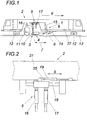
- a tamping machine 2 ( Fig. 1 ) has a tamping unit 11 and a main lifting device 4 with lifting cylinders 17, with roller tongs 24 and an integrated additional lifting device 3 with lifting cylinder 16 for leveling and straightening a track 13 and a track 31 branching off from track 13 in the area of a switch.
- the additional lifting device 3 comprises a telescopic support arm 10, 20, which at one end has a rail mount with guide roller 21 and roller tongs 22 and which is mounted on the main lifting device 4 so as to be rotatable about an axis 28 parallel to the tamping machine's longitudinal axis, whereby the pivoting angle of the support arm 10, 20 is adjusted a lifting drive 16 is provided opposite the main lifting device 4.
- the support arm 10 is freely pivotable on a frame of the main lifting device 4 and the pivot angle of the supporting arm 10, 20 relative to the main lifting device 4 or its frame can be adjusted with the lifting drive 16.
- the auxiliary lifting device 3 comprises two Telescopic support arms 10, 20, one being assigned to a track 31 branching off to the right in the area of a switch from track 13 and the other being assignable to a track 31 branching off to the left in the area of a switch from track 13.
- the main lifting device 4 can be moved in the longitudinal direction 8 of the track together with the additional lifting device 3 via a displacement drive 14 with integrated path measurement.
- the turnout tamping machine 2 can be moved on the track 13 via drives 12.
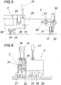
- the working direction of the switch tamping machine is indicated by 6. 5 shows the displacement device of the articulation points of the lifting drives 16, 17 which are displaced in the longitudinal direction synchronously with the displacement 8 of the main lifting unit 4.
- the path 8 of the displacement device 14 measured with an integrated displacement measurement 14 is specified as a setpoint value for the displacement device 5 of the articulation points of the lifting drives 16, 17.
- the displacement device 5 ( Fig. 2 ) for the lifting drives of the main lifting unit 17 and the additional lifting unit 16 consists of the guide 18 and the displacement drive 8, as well as an integrated displacement measuring device 35.
- the displacement device 5 is connected to the frame 27 of the tamping machine 2.
- FIG. 3 shows schematically a switch with a dashed representation of the frame outlines 27 of the tamping machine 2 in the working direction 6.
- the auxiliary lifting device with the extended support arm 20 and the lifting tool is directly linked to the main lifting unit 4.
- FIG. 7 shows the great distance between an additional lifting device 9 from the prior art and the lifting tools of the main lifting device 4.
- 31 shows the branching line, 33 the long sleepers and 32 the continuous main line of the switch.
- the additional lifting device 3 is hinged 28 directly to the main lifting unit 4.
- the guide roller 21 is placed on the rail 13 via the extendable support arm 20 and carried along with it, with the aid of the roller tongs 22 and the additional lifting drive 16 the branching line is lifted with it.
- the main lifting device 4 is connected to the continuous rail and lifted by means of its lifting tools, the roller tongs 24 or the lifting hook 25.
- the outline of the machine frame 27 of the track tamping machine 2 is indicated schematically in the picture.
- Fig. 5 shows the embodiment according to the invention of the auxiliary lifting device 3, 10 integrated in the main lifting device 4 and the extended support arm 20.
- a distance sensor 34 measures the height difference between the main lifting device 4 and the support arm 10 of the additional lifting device 3.
- the additional lifting device 3 is guided via the guide roller 21 on the branching track 31; the roller tong drive 30 closes the roller tong 22.
- 28 shows the pivot point of the left-facing auxiliary elevator.
- the main lifting device 4 is guided over the guide straightening roller 26.
- the main lifting device 4 has a lifting roller, the roller tongs 24, and a lifting hook 25.
- the support arm of the additional lifting device 3 is lifted via the lifting drive 16.
- the lifting device of the additional lifting device 3 can be adjusted tangentially to the course of the rail via a rotary drive 29 and the swivel joint 23.
- Fig. 6 shows the main lifting device 4 with the integrated auxiliary lifting device 3 in a side view.
- the figure shows the main lifting drive 17 and the additional lifting drives 16.
Claims (5)
- Machine de bourrage (2) pour compacter le lit de ballast d'une voie ferrée (13), avec deux rails, avec des groupes de bourrage (11) destinés à tasser la voie ferrée (13), avec un dispositif de levage principal (4) disposé entre des disques (12) dans la direction de travail (6), de préférence devant les groupes de bourrage (11), avec des vérins de levage (17) et avec des pinces à rouleaux (24) pour le nivellement et le redressement des deux rails de la voie ferrée (13) et avec un dispositif de levage supplémentaire (3) pour le nivellement et le redressement d'une voie ferrée (31) bifurquant de la voie ferrée (13) dans la zone d'un aiguillage, dans lequel le dispositif de levage supplémentaire (3) comporte un bras de support télescopique (10, 20), qui présente, à une extrémité, un logement de rail, en particulier avec galet de guidage (21) et pince à rouleaux (22), et qui, à l'autre extrémité, est monté de façon à pouvoir tourner autour d'un axe (28) parallèle à l'axe longitudinal de la machine de bourrage sur le dispositif de levage principal (4) et un dispositif d'entraînement de levage (16) étant prévu pour le réglage de l'angle de pivotement du bras de support (10, 20) par rapport au dispositif de levage principal (4), caractérisée en ce que les dispositifs d'entraînement de levage (17) associés au dispositif de levage principal (4) et les dispositifs d'entraînement de levage (16) associés au dispositif de levage supplémentaire (3) peuvent être déplacés par le biais d'un dispositif d'entraînement de déplacement (5) dans le sens longitudinal de la machine de bourrage (8), les dispositifs d'entraînement de levage (16, 17) étant placés sur un chariot commun et pouvant être déplacés avec celui-ci dans le sens longitudinal de la machine de bourrage (8).
- Machine de bourrage selon la revendication 1, caractérisée en ce que le dispositif de levage supplémentaire (3) comporte deux bras de support télescopiques (10, 20), un pouvant être associé, vu dans la direction de travail (6), à une voie ferrée (31) bifurquant à droite dans la zone de l'aiguillage de la voie ferrée (13), et l'autre pouvant être associé à la voie ferrée (31) bifurquant à gauche dans la zone d'un aiguillage de la voie ferrée (13).
- Machine de bourrage selon la revendication 1, caractérisée en ce qu'un capteur de course (35) est associé au dispositif d'entraînement de déplacement (5) du dispositif de levage principal (4) et du dispositif de levage supplémentaire (3), en ce qu'un deuxième dispositif d'entraînement de déplacement (14) est associé au dispositif de levage principal (4) et ainsi, au dispositif de levage supplémentaire (3), et en ce que le dispositif de levage principal (4) peut être déplacé avec le dispositif d'entraînement de déplacement (5) et avec le dispositif d'entraînement de déplacement (14) de manière synchrone dans le sens longitudinal de la machine de bourrage (8).
- Machine de bourrage selon l'une des revendications 1 à 3, caractérisée en ce que, pour définir la différence de hauteur entre le dispositif de levage principal (4) et le bras de support (10) du dispositif de levage supplémentaire (3), il est prévu un capteur de distance (34) et en ce que le bras de support (10) peut être déplacé avec le dispositif d'entraînement de levage (16) associé, dans le plan ascenseur principal du dispositif de levage principal (4).
- Machine de bourrage selon l'une des revendications 1 à 4, caractérisée en ce que le galet de guidage (21) et la pince à rouleaux (22) sont en prise par le biais d'une articulation (23) avec l'axe de pivotement vertical, au niveau du bras de support télescopique (20), et en ce qu'il est prévu un dispositif d'entraînement en rotation (29) avec lequel le galet de guidage (21) et la pince à rouleaux (22) peuvent être réglés autour de l'axe de pivotement.
Applications Claiming Priority (1)
| Application Number | Priority Date | Filing Date | Title |
|---|---|---|---|
| ATA50733/2014A AT516358B1 (de) | 2014-10-14 | 2014-10-14 | Stopfmaschine zum Verdichten der Schotterbettung eines Gleises |
Publications (3)
| Publication Number | Publication Date |
|---|---|
| EP3009564A1 EP3009564A1 (fr) | 2016-04-20 |
| EP3009564B1 EP3009564B1 (fr) | 2017-08-16 |
| EP3009564B2 true EP3009564B2 (fr) | 2020-11-11 |
Family
ID=54292735
Family Applications (1)
| Application Number | Title | Priority Date | Filing Date |
|---|---|---|---|
| EP15189328.6A Active EP3009564B2 (fr) | 2014-10-14 | 2015-10-12 | Machine de bourrage destinee a comprimer le lit de ballast d'une voie ferree |
Country Status (4)
| Country | Link |
|---|---|
| EP (1) | EP3009564B2 (fr) |
| AT (1) | AT516358B1 (fr) |
| ES (1) | ES2647599T5 (fr) |
| NO (1) | NO3009564T3 (fr) |
Families Citing this family (3)
| Publication number | Priority date | Publication date | Assignee | Title |
|---|---|---|---|---|
| AT520824B1 (de) * | 2018-05-24 | 2019-08-15 | Plasser & Theurer Export Von Bahnbaumaschinen Gmbh | Verfahren und Maschine zum Unterstopfen eines Gleises im Bereich einer Weiche |
| CN110453549A (zh) * | 2019-08-21 | 2019-11-15 | 长沙瀚鹏电子技术有限公司 | 一种铁路道岔捣固车自动作业实现方法和装置 |
| CN112482350B (zh) * | 2020-10-28 | 2022-01-21 | 国网山东省电力公司菏泽市定陶区供电公司 | 一种电力施工用夯实装置 |
Citations (4)
| Publication number | Priority date | Publication date | Assignee | Title |
|---|---|---|---|---|
| AT387607B (de) † | 1987-07-08 | 1989-02-27 | Plasser Bahnbaumasch Franz | Fahrbare gleisstopf-, hebe- und richtmaschine fuer den weichen- und kreuzungsbereich |
| AT3739U2 (de) † | 2000-04-07 | 2000-07-25 | Plasser Bahnbaumasch Franz | Stopfmaschine |
| RU2338823C2 (ru) † | 2006-10-06 | 2008-11-20 | Открытое акционерное общество Калужский завод "Ремпутьмаш" | Выправочно-подбивочно-рихтовочная машина |
| AT508755A4 (de) † | 2010-03-01 | 2011-04-15 | Plasser Bahnbaumasch Franz | Stopfmaschine mit einer zusatzhebeeinrichtung |
Family Cites Families (5)
| Publication number | Priority date | Publication date | Assignee | Title |
|---|---|---|---|---|
| DE2505482A1 (de) * | 1975-02-10 | 1976-08-19 | Wilhelm Spoeckner | Hebevorrichtung fuer weichen |
| AT356165B (de) * | 1978-05-11 | 1980-04-10 | Plasser Bahnbaumasch Franz | Gleisstopfmaschine mit gleishebe- und seiten- richtvorrichtung, insbesondere fuer weichen- bereiche |
| ES2023678B3 (es) | 1987-11-05 | 1992-02-01 | Franz Plasser Bahnbaumaschinen- Ind M B H | Bateadora de balasto, elevadora y enderezadora portatil para elevacion y/o deslizamiento transversal de un sector de via en la zona de cambio de via y cruce. |
| SK278307B6 (en) * | 1992-03-25 | 1996-09-04 | Josef Theurer | Track tamping machine |
| AT3877U3 (de) | 2000-06-09 | 2001-03-26 | Plasser Bahnbaumasch Franz | Stopfmaschine |
-
2014
- 2014-10-14 AT ATA50733/2014A patent/AT516358B1/de active
-
2015
- 2015-10-12 ES ES15189328T patent/ES2647599T5/es active Active
- 2015-10-12 EP EP15189328.6A patent/EP3009564B2/fr active Active
- 2015-10-12 NO NO15189328A patent/NO3009564T3/no unknown
Patent Citations (4)
| Publication number | Priority date | Publication date | Assignee | Title |
|---|---|---|---|---|
| AT387607B (de) † | 1987-07-08 | 1989-02-27 | Plasser Bahnbaumasch Franz | Fahrbare gleisstopf-, hebe- und richtmaschine fuer den weichen- und kreuzungsbereich |
| AT3739U2 (de) † | 2000-04-07 | 2000-07-25 | Plasser Bahnbaumasch Franz | Stopfmaschine |
| RU2338823C2 (ru) † | 2006-10-06 | 2008-11-20 | Открытое акционерное общество Калужский завод "Ремпутьмаш" | Выправочно-подбивочно-рихтовочная машина |
| AT508755A4 (de) † | 2010-03-01 | 2011-04-15 | Plasser Bahnbaumasch Franz | Stopfmaschine mit einer zusatzhebeeinrichtung |
Also Published As
| Publication number | Publication date |
|---|---|
| EP3009564B1 (fr) | 2017-08-16 |
| AT516358B1 (de) | 2017-01-15 |
| NO3009564T3 (fr) | 2018-01-13 |
| ES2647599T3 (es) | 2017-12-22 |
| EP3009564A1 (fr) | 2016-04-20 |
| ES2647599T5 (es) | 2021-08-11 |
| AT516358A1 (de) | 2016-04-15 |
Similar Documents
| Publication | Publication Date | Title |
|---|---|---|
| DE2928474C2 (fr) | ||
| AT391502B (de) | Fahrbare gleisstopf-, hebe- und richtmaschine zum heben und bzw. oder seitwaertsverschieben eines gleises im weichen- und kreuzungsbereich | |
| EP3204557B2 (fr) | Bourreuse mécanique servant à compacter le lit de ballast d'une voie | |
| DE3313207C2 (fr) | ||
| EP1738028B1 (fr) | Machine pour transporter des aiguillages | |
| DE2853529C2 (de) | Fahrbare Gleisstopfmaschine mit einer Vorrichtung zum Anheben und bzw. oder Seitenrichten des Gleises | |
| EP3009564B2 (fr) | Machine de bourrage destinee a comprimer le lit de ballast d'une voie ferree | |
| DD283435A5 (de) | Fahrbare gleisstopf-, hebe- und richtmaschine | |
| EP1736602A1 (fr) | Machine à tendre des rails de chemin de fer pour les souder | |
| EP0584055B1 (fr) | Machine de bourrage des aiguilles et croisements d'une voie | |
| EP2286030B1 (fr) | Bourreuse | |
| EP3303703B1 (fr) | Bourreuse destinée au tassement du lit de ballast d'une voie ferroviaire | |
| AT400337B (de) | Gleisstopfmaschine mit in gleisquerrichtung verstellbaren stopfeinheiten | |
| DE3110832C2 (de) | Fahrbare Gleisbaumaschine mit einer Gleislage-Korrekturvorrichtung | |
| CH665860A5 (de) | Fahrbare gleisstopf-nivellier- und richtmaschine. | |
| EP1162310B1 (fr) | Bourreuse | |
| DE2737778A1 (de) | Gleisstopfmaschine, insbesondere zum unterstopfen von gleis-weichen | |
| DE2649797C2 (de) | Gleiswartungsmaschine für das Nivellieren und Richten von Weichen und Kreuzungen | |
| DE3122647C2 (fr) | ||
| AT525020B1 (de) | Stopfmaschine zum Verdichten der Schotterbettung eines Gleises | |
| DE1708652B2 (de) | Anhebevorrichtung fuer eine einzelne schiene eines eisenbahngleises | |
| DE1708652C3 (de) | Anhebevorrichtung für eine einzelne Schiene eines Eisenbahngleises | |
| EP2318252B1 (fr) | Véhicule doté d'une plateforme de travail | |
| DE1534088C3 (de) | Fahrbare Gleisstopfmaschine mit einer Gleishebevorrichtung | |
| DD252404A5 (de) | Maschinenanordnung und verfahren zum plastischen biegen der enden von verschweissten bzw. nichtverschweissten schienen im bereich der schienenstoesse verlegter gleise |
Legal Events
| Date | Code | Title | Description |
|---|---|---|---|
| PUAI | Public reference made under article 153(3) epc to a published international application that has entered the european phase |
Free format text: ORIGINAL CODE: 0009012 |
|
| AK | Designated contracting states |
Kind code of ref document: A1 Designated state(s): AL AT BE BG CH CY CZ DE DK EE ES FI FR GB GR HR HU IE IS IT LI LT LU LV MC MK MT NL NO PL PT RO RS SE SI SK SM TR |
|
| AX | Request for extension of the european patent |
Extension state: BA ME |
|
| 17P | Request for examination filed |
Effective date: 20161019 |
|
| RBV | Designated contracting states (corrected) |
Designated state(s): AL AT BE BG CH CY CZ DE DK EE ES FI FR GB GR HR HU IE IS IT LI LT LU LV MC MK MT NL NO PL PT RO RS SE SI SK SM TR |
|
| RAP1 | Party data changed (applicant data changed or rights of an application transferred) |
Owner name: HP3 REAL GMBH |
|
| GRAP | Despatch of communication of intention to grant a patent |
Free format text: ORIGINAL CODE: EPIDOSNIGR1 |
|
| STAA | Information on the status of an ep patent application or granted ep patent |
Free format text: STATUS: GRANT OF PATENT IS INTENDED |
|
| INTG | Intention to grant announced |
Effective date: 20170504 |
|
| GRAS | Grant fee paid |
Free format text: ORIGINAL CODE: EPIDOSNIGR3 |
|
| GRAA | (expected) grant |
Free format text: ORIGINAL CODE: 0009210 |
|
| STAA | Information on the status of an ep patent application or granted ep patent |
Free format text: STATUS: THE PATENT HAS BEEN GRANTED |
|
| AK | Designated contracting states |
Kind code of ref document: B1 Designated state(s): AL AT BE BG CH CY CZ DE DK EE ES FI FR GB GR HR HU IE IS IT LI LT LU LV MC MK MT NL NO PL PT RO RS SE SI SK SM TR |
|
| REG | Reference to a national code |
Ref country code: GB Ref legal event code: FG4D Free format text: NOT ENGLISH |
|
| REG | Reference to a national code |
Ref country code: CH Ref legal event code: EP |
|
| REG | Reference to a national code |
Ref country code: IE Ref legal event code: FG4D Free format text: LANGUAGE OF EP DOCUMENT: GERMAN |
|
| REG | Reference to a national code |
Ref country code: AT Ref legal event code: REF Ref document number: 919157 Country of ref document: AT Kind code of ref document: T Effective date: 20170915 |
|
| REG | Reference to a national code |
Ref country code: DE Ref legal event code: R096 Ref document number: 502015001681 Country of ref document: DE |
|
| REG | Reference to a national code |
Ref country code: CH Ref legal event code: NV Representative=s name: E. BLUM AND CO. AG PATENT- UND MARKENANWAELTE , CH Ref country code: FR Ref legal event code: PLFP Year of fee payment: 3 |
|
| REG | Reference to a national code |
Ref country code: SE Ref legal event code: TRGR |
|
| REG | Reference to a national code |
Ref country code: NL Ref legal event code: MP Effective date: 20170816 |
|
| REG | Reference to a national code |
Ref country code: ES Ref legal event code: FG2A Ref document number: 2647599 Country of ref document: ES Kind code of ref document: T3 Effective date: 20171222 |
|
| REG | Reference to a national code |
Ref country code: LT Ref legal event code: MG4D |
|
| REG | Reference to a national code |
Ref country code: NO Ref legal event code: T2 Effective date: 20170816 |
|
| PG25 | Lapsed in a contracting state [announced via postgrant information from national office to epo] |
Ref country code: LT Free format text: LAPSE BECAUSE OF FAILURE TO SUBMIT A TRANSLATION OF THE DESCRIPTION OR TO PAY THE FEE WITHIN THE PRESCRIBED TIME-LIMIT Effective date: 20170816 Ref country code: NL Free format text: LAPSE BECAUSE OF FAILURE TO SUBMIT A TRANSLATION OF THE DESCRIPTION OR TO PAY THE FEE WITHIN THE PRESCRIBED TIME-LIMIT Effective date: 20170816 |
|
| PG25 | Lapsed in a contracting state [announced via postgrant information from national office to epo] |
Ref country code: GR Free format text: LAPSE BECAUSE OF FAILURE TO SUBMIT A TRANSLATION OF THE DESCRIPTION OR TO PAY THE FEE WITHIN THE PRESCRIBED TIME-LIMIT Effective date: 20171117 Ref country code: LV Free format text: LAPSE BECAUSE OF FAILURE TO SUBMIT A TRANSLATION OF THE DESCRIPTION OR TO PAY THE FEE WITHIN THE PRESCRIBED TIME-LIMIT Effective date: 20170816 Ref country code: IS Free format text: LAPSE BECAUSE OF FAILURE TO SUBMIT A TRANSLATION OF THE DESCRIPTION OR TO PAY THE FEE WITHIN THE PRESCRIBED TIME-LIMIT Effective date: 20171216 Ref country code: BG Free format text: LAPSE BECAUSE OF FAILURE TO SUBMIT A TRANSLATION OF THE DESCRIPTION OR TO PAY THE FEE WITHIN THE PRESCRIBED TIME-LIMIT Effective date: 20171116 Ref country code: RS Free format text: LAPSE BECAUSE OF FAILURE TO SUBMIT A TRANSLATION OF THE DESCRIPTION OR TO PAY THE FEE WITHIN THE PRESCRIBED TIME-LIMIT Effective date: 20170816 Ref country code: PL Free format text: LAPSE BECAUSE OF FAILURE TO SUBMIT A TRANSLATION OF THE DESCRIPTION OR TO PAY THE FEE WITHIN THE PRESCRIBED TIME-LIMIT Effective date: 20170816 |
|
| PG25 | Lapsed in a contracting state [announced via postgrant information from national office to epo] |
Ref country code: RO Free format text: LAPSE BECAUSE OF FAILURE TO SUBMIT A TRANSLATION OF THE DESCRIPTION OR TO PAY THE FEE WITHIN THE PRESCRIBED TIME-LIMIT Effective date: 20170816 Ref country code: CZ Free format text: LAPSE BECAUSE OF FAILURE TO SUBMIT A TRANSLATION OF THE DESCRIPTION OR TO PAY THE FEE WITHIN THE PRESCRIBED TIME-LIMIT Effective date: 20170816 Ref country code: DK Free format text: LAPSE BECAUSE OF FAILURE TO SUBMIT A TRANSLATION OF THE DESCRIPTION OR TO PAY THE FEE WITHIN THE PRESCRIBED TIME-LIMIT Effective date: 20170816 |
|
| REG | Reference to a national code |
Ref country code: DE Ref legal event code: R026 Ref document number: 502015001681 Country of ref document: DE |
|
| PLBI | Opposition filed |
Free format text: ORIGINAL CODE: 0009260 |
|
| PG25 | Lapsed in a contracting state [announced via postgrant information from national office to epo] |
Ref country code: SM Free format text: LAPSE BECAUSE OF FAILURE TO SUBMIT A TRANSLATION OF THE DESCRIPTION OR TO PAY THE FEE WITHIN THE PRESCRIBED TIME-LIMIT Effective date: 20170816 Ref country code: EE Free format text: LAPSE BECAUSE OF FAILURE TO SUBMIT A TRANSLATION OF THE DESCRIPTION OR TO PAY THE FEE WITHIN THE PRESCRIBED TIME-LIMIT Effective date: 20170816 Ref country code: SK Free format text: LAPSE BECAUSE OF FAILURE TO SUBMIT A TRANSLATION OF THE DESCRIPTION OR TO PAY THE FEE WITHIN THE PRESCRIBED TIME-LIMIT Effective date: 20170816 Ref country code: MC Free format text: LAPSE BECAUSE OF FAILURE TO SUBMIT A TRANSLATION OF THE DESCRIPTION OR TO PAY THE FEE WITHIN THE PRESCRIBED TIME-LIMIT Effective date: 20170816 |
|
| PLAX | Notice of opposition and request to file observation + time limit sent |
Free format text: ORIGINAL CODE: EPIDOSNOBS2 |
|
| 26 | Opposition filed |
Opponent name: PLASSER & THEURER, EXPORT VON BAHNBAUMASCHINEN, GE Effective date: 20180511 |
|
| REG | Reference to a national code |
Ref country code: IE Ref legal event code: MM4A |
|
| PG25 | Lapsed in a contracting state [announced via postgrant information from national office to epo] |
Ref country code: LU Free format text: LAPSE BECAUSE OF NON-PAYMENT OF DUE FEES Effective date: 20171012 |
|
| REG | Reference to a national code |
Ref country code: BE Ref legal event code: MM Effective date: 20171031 |
|
| PG25 | Lapsed in a contracting state [announced via postgrant information from national office to epo] |
Ref country code: BE Free format text: LAPSE BECAUSE OF NON-PAYMENT OF DUE FEES Effective date: 20171031 Ref country code: SI Free format text: LAPSE BECAUSE OF FAILURE TO SUBMIT A TRANSLATION OF THE DESCRIPTION OR TO PAY THE FEE WITHIN THE PRESCRIBED TIME-LIMIT Effective date: 20170816 |
|
| PG25 | Lapsed in a contracting state [announced via postgrant information from national office to epo] |
Ref country code: MT Free format text: LAPSE BECAUSE OF FAILURE TO SUBMIT A TRANSLATION OF THE DESCRIPTION OR TO PAY THE FEE WITHIN THE PRESCRIBED TIME-LIMIT Effective date: 20170816 |
|
| PLBB | Reply of patent proprietor to notice(s) of opposition received |
Free format text: ORIGINAL CODE: EPIDOSNOBS3 |
|
| REG | Reference to a national code |
Ref country code: FR Ref legal event code: PLFP Year of fee payment: 4 |
|
| PG25 | Lapsed in a contracting state [announced via postgrant information from national office to epo] |
Ref country code: IE Free format text: LAPSE BECAUSE OF NON-PAYMENT OF DUE FEES Effective date: 20171012 |
|
| PG25 | Lapsed in a contracting state [announced via postgrant information from national office to epo] |
Ref country code: HU Free format text: LAPSE BECAUSE OF FAILURE TO SUBMIT A TRANSLATION OF THE DESCRIPTION OR TO PAY THE FEE WITHIN THE PRESCRIBED TIME-LIMIT; INVALID AB INITIO Effective date: 20151012 |
|
| PG25 | Lapsed in a contracting state [announced via postgrant information from national office to epo] |
Ref country code: CY Free format text: LAPSE BECAUSE OF FAILURE TO SUBMIT A TRANSLATION OF THE DESCRIPTION OR TO PAY THE FEE WITHIN THE PRESCRIBED TIME-LIMIT Effective date: 20170816 |
|
| PG25 | Lapsed in a contracting state [announced via postgrant information from national office to epo] |
Ref country code: MK Free format text: LAPSE BECAUSE OF FAILURE TO SUBMIT A TRANSLATION OF THE DESCRIPTION OR TO PAY THE FEE WITHIN THE PRESCRIBED TIME-LIMIT Effective date: 20170816 |
|
| PG25 | Lapsed in a contracting state [announced via postgrant information from national office to epo] |
Ref country code: TR Free format text: LAPSE BECAUSE OF FAILURE TO SUBMIT A TRANSLATION OF THE DESCRIPTION OR TO PAY THE FEE WITHIN THE PRESCRIBED TIME-LIMIT Effective date: 20170816 |
|
| PG25 | Lapsed in a contracting state [announced via postgrant information from national office to epo] |
Ref country code: PT Free format text: LAPSE BECAUSE OF FAILURE TO SUBMIT A TRANSLATION OF THE DESCRIPTION OR TO PAY THE FEE WITHIN THE PRESCRIBED TIME-LIMIT Effective date: 20170816 |
|
| PG25 | Lapsed in a contracting state [announced via postgrant information from national office to epo] |
Ref country code: HR Free format text: LAPSE BECAUSE OF FAILURE TO SUBMIT A TRANSLATION OF THE DESCRIPTION OR TO PAY THE FEE WITHIN THE PRESCRIBED TIME-LIMIT Effective date: 20170816 |
|
| PG25 | Lapsed in a contracting state [announced via postgrant information from national office to epo] |
Ref country code: AL Free format text: LAPSE BECAUSE OF FAILURE TO SUBMIT A TRANSLATION OF THE DESCRIPTION OR TO PAY THE FEE WITHIN THE PRESCRIBED TIME-LIMIT Effective date: 20170816 |
|
| PUAH | Patent maintained in amended form |
Free format text: ORIGINAL CODE: 0009272 |
|
| STAA | Information on the status of an ep patent application or granted ep patent |
Free format text: STATUS: PATENT MAINTAINED AS AMENDED |
|
| REG | Reference to a national code |
Ref country code: CH Ref legal event code: AELC |
|
| 27A | Patent maintained in amended form |
Effective date: 20201111 |
|
| AK | Designated contracting states |
Kind code of ref document: B2 Designated state(s): AL AT BE BG CH CY CZ DE DK EE ES FI FR GB GR HR HU IE IS IT LI LT LU LV MC MK MT NL NO PL PT RO RS SE SI SK SM TR |
|
| REG | Reference to a national code |
Ref country code: DE Ref legal event code: R102 Ref document number: 502015001681 Country of ref document: DE |
|
| REG | Reference to a national code |
Ref country code: SE Ref legal event code: RPEO |
|
| REG | Reference to a national code |
Ref country code: NO Ref legal event code: TB2 |
|
| REG | Reference to a national code |
Ref country code: ES Ref legal event code: DC2A Ref document number: 2647599 Country of ref document: ES Kind code of ref document: T5 Effective date: 20210811 |
|
| REG | Reference to a national code |
Ref country code: AT Ref legal event code: MM01 Ref document number: 919157 Country of ref document: AT Kind code of ref document: T Effective date: 20201012 |
|
| PG25 | Lapsed in a contracting state [announced via postgrant information from national office to epo] |
Ref country code: AT Free format text: LAPSE BECAUSE OF NON-PAYMENT OF DUE FEES Effective date: 20201012 |
|
| P01 | Opt-out of the competence of the unified patent court (upc) registered |
Effective date: 20230428 |
|
| PGFP | Annual fee paid to national office [announced via postgrant information from national office to epo] |
Ref country code: GB Payment date: 20231024 Year of fee payment: 9 |
|
| PGFP | Annual fee paid to national office [announced via postgrant information from national office to epo] |
Ref country code: ES Payment date: 20231110 Year of fee payment: 9 |
|
| PGFP | Annual fee paid to national office [announced via postgrant information from national office to epo] |
Ref country code: SE Payment date: 20231023 Year of fee payment: 9 Ref country code: NO Payment date: 20231018 Year of fee payment: 9 Ref country code: IT Payment date: 20231024 Year of fee payment: 9 Ref country code: FR Payment date: 20231026 Year of fee payment: 9 Ref country code: FI Payment date: 20231026 Year of fee payment: 9 Ref country code: DE Payment date: 20231027 Year of fee payment: 9 Ref country code: CH Payment date: 20231102 Year of fee payment: 9 |