EP3009301A1 - Phare automobile - Google Patents
Phare automobile Download PDFInfo
- Publication number
- EP3009301A1 EP3009301A1 EP15189660.2A EP15189660A EP3009301A1 EP 3009301 A1 EP3009301 A1 EP 3009301A1 EP 15189660 A EP15189660 A EP 15189660A EP 3009301 A1 EP3009301 A1 EP 3009301A1
- Authority
- EP
- European Patent Office
- Prior art keywords
- light
- light source
- supporting structure
- shell
- planar
- Prior art date
- Legal status (The legal status is an assumption and is not a legal conclusion. Google has not performed a legal analysis and makes no representation as to the accuracy of the status listed.)
- Granted
Links
- 239000000463 material Substances 0.000 claims abstract description 28
- 230000001464 adherent effect Effects 0.000 claims description 3
- 230000000712 assembly Effects 0.000 description 13
- 238000000429 assembly Methods 0.000 description 13
- 229920003023 plastic Polymers 0.000 description 7
- 239000004926 polymethyl methacrylate Substances 0.000 description 6
- 238000001746 injection moulding Methods 0.000 description 5
- 230000001795 light effect Effects 0.000 description 4
- 239000004033 plastic Substances 0.000 description 4
- 229920005372 Plexiglas® Polymers 0.000 description 3
- 229920003229 poly(methyl methacrylate) Polymers 0.000 description 3
- 229920000515 polycarbonate Polymers 0.000 description 3
- 239000004417 polycarbonate Substances 0.000 description 3
- 238000006243 chemical reaction Methods 0.000 description 2
- 230000000295 complement effect Effects 0.000 description 2
- 239000013307 optical fiber Substances 0.000 description 2
- 230000000284 resting effect Effects 0.000 description 2
- 239000003086 colorant Substances 0.000 description 1
- 230000005611 electricity Effects 0.000 description 1
- 238000012986 modification Methods 0.000 description 1
- 230000004048 modification Effects 0.000 description 1
Images

Classifications
-
- B—PERFORMING OPERATIONS; TRANSPORTING
- B60—VEHICLES IN GENERAL
- B60Q—ARRANGEMENT OF SIGNALLING OR LIGHTING DEVICES, THE MOUNTING OR SUPPORTING THEREOF OR CIRCUITS THEREFOR, FOR VEHICLES IN GENERAL
- B60Q1/00—Arrangement of optical signalling or lighting devices, the mounting or supporting thereof or circuits therefor
- B60Q1/26—Arrangement of optical signalling or lighting devices, the mounting or supporting thereof or circuits therefor the devices being primarily intended to indicate the vehicle, or parts thereof, or to give signals, to other traffic
- B60Q1/2607—Arrangement of optical signalling or lighting devices, the mounting or supporting thereof or circuits therefor the devices being primarily intended to indicate the vehicle, or parts thereof, or to give signals, to other traffic comprising at least two indicating lamps
-
- B—PERFORMING OPERATIONS; TRANSPORTING
- B60—VEHICLES IN GENERAL
- B60Q—ARRANGEMENT OF SIGNALLING OR LIGHTING DEVICES, THE MOUNTING OR SUPPORTING THEREOF OR CIRCUITS THEREFOR, FOR VEHICLES IN GENERAL
- B60Q1/00—Arrangement of optical signalling or lighting devices, the mounting or supporting thereof or circuits therefor
- B60Q1/0029—Spatial arrangement
- B60Q1/0041—Spatial arrangement of several lamps in relation to each other
- B60Q1/0058—Stacked, i.e. one lamp located behind the other in the optical axis direction
-
- F—MECHANICAL ENGINEERING; LIGHTING; HEATING; WEAPONS; BLASTING
- F21—LIGHTING
- F21S—NON-PORTABLE LIGHTING DEVICES; SYSTEMS THEREOF; VEHICLE LIGHTING DEVICES SPECIALLY ADAPTED FOR VEHICLE EXTERIORS
- F21S43/00—Signalling devices specially adapted for vehicle exteriors, e.g. brake lamps, direction indicator lights or reversing lights
- F21S43/10—Signalling devices specially adapted for vehicle exteriors, e.g. brake lamps, direction indicator lights or reversing lights characterised by the light source
- F21S43/13—Signalling devices specially adapted for vehicle exteriors, e.g. brake lamps, direction indicator lights or reversing lights characterised by the light source characterised by the type of light source
- F21S43/14—Light emitting diodes [LED]
- F21S43/145—Surface emitters, e.g. organic light emitting diodes [OLED]
-
- F—MECHANICAL ENGINEERING; LIGHTING; HEATING; WEAPONS; BLASTING
- F21—LIGHTING
- F21S—NON-PORTABLE LIGHTING DEVICES; SYSTEMS THEREOF; VEHICLE LIGHTING DEVICES SPECIALLY ADAPTED FOR VEHICLE EXTERIORS
- F21S43/00—Signalling devices specially adapted for vehicle exteriors, e.g. brake lamps, direction indicator lights or reversing lights
- F21S43/10—Signalling devices specially adapted for vehicle exteriors, e.g. brake lamps, direction indicator lights or reversing lights characterised by the light source
- F21S43/19—Attachment of light sources or lamp holders
-
- F—MECHANICAL ENGINEERING; LIGHTING; HEATING; WEAPONS; BLASTING
- F21—LIGHTING
- F21S—NON-PORTABLE LIGHTING DEVICES; SYSTEMS THEREOF; VEHICLE LIGHTING DEVICES SPECIALLY ADAPTED FOR VEHICLE EXTERIORS
- F21S43/00—Signalling devices specially adapted for vehicle exteriors, e.g. brake lamps, direction indicator lights or reversing lights
- F21S43/20—Signalling devices specially adapted for vehicle exteriors, e.g. brake lamps, direction indicator lights or reversing lights characterised by refractors, transparent cover plates, light guides or filters
- F21S43/235—Light guides
- F21S43/236—Light guides characterised by the shape of the light guide
- F21S43/239—Light guides characterised by the shape of the light guide plate-shaped
-
- F—MECHANICAL ENGINEERING; LIGHTING; HEATING; WEAPONS; BLASTING
- F21—LIGHTING
- F21S—NON-PORTABLE LIGHTING DEVICES; SYSTEMS THEREOF; VEHICLE LIGHTING DEVICES SPECIALLY ADAPTED FOR VEHICLE EXTERIORS
- F21S43/00—Signalling devices specially adapted for vehicle exteriors, e.g. brake lamps, direction indicator lights or reversing lights
- F21S43/20—Signalling devices specially adapted for vehicle exteriors, e.g. brake lamps, direction indicator lights or reversing lights characterised by refractors, transparent cover plates, light guides or filters
- F21S43/235—Light guides
- F21S43/236—Light guides characterised by the shape of the light guide
- F21S43/241—Light guides characterised by the shape of the light guide of complex shape
-
- F—MECHANICAL ENGINEERING; LIGHTING; HEATING; WEAPONS; BLASTING
- F21—LIGHTING
- F21S—NON-PORTABLE LIGHTING DEVICES; SYSTEMS THEREOF; VEHICLE LIGHTING DEVICES SPECIALLY ADAPTED FOR VEHICLE EXTERIORS
- F21S43/00—Signalling devices specially adapted for vehicle exteriors, e.g. brake lamps, direction indicator lights or reversing lights
- F21S43/20—Signalling devices specially adapted for vehicle exteriors, e.g. brake lamps, direction indicator lights or reversing lights characterised by refractors, transparent cover plates, light guides or filters
- F21S43/235—Light guides
- F21S43/242—Light guides characterised by the emission area
- F21S43/245—Light guides characterised by the emission area emitting light from one or more of its major surfaces
-
- F—MECHANICAL ENGINEERING; LIGHTING; HEATING; WEAPONS; BLASTING
- F21—LIGHTING
- F21S—NON-PORTABLE LIGHTING DEVICES; SYSTEMS THEREOF; VEHICLE LIGHTING DEVICES SPECIALLY ADAPTED FOR VEHICLE EXTERIORS
- F21S43/00—Signalling devices specially adapted for vehicle exteriors, e.g. brake lamps, direction indicator lights or reversing lights
- F21S43/20—Signalling devices specially adapted for vehicle exteriors, e.g. brake lamps, direction indicator lights or reversing lights characterised by refractors, transparent cover plates, light guides or filters
- F21S43/235—Light guides
- F21S43/247—Light guides with a single light source being coupled into the light guide
-
- F—MECHANICAL ENGINEERING; LIGHTING; HEATING; WEAPONS; BLASTING
- F21—LIGHTING
- F21S—NON-PORTABLE LIGHTING DEVICES; SYSTEMS THEREOF; VEHICLE LIGHTING DEVICES SPECIALLY ADAPTED FOR VEHICLE EXTERIORS
- F21S43/00—Signalling devices specially adapted for vehicle exteriors, e.g. brake lamps, direction indicator lights or reversing lights
- F21S43/20—Signalling devices specially adapted for vehicle exteriors, e.g. brake lamps, direction indicator lights or reversing lights characterised by refractors, transparent cover plates, light guides or filters
- F21S43/27—Attachment thereof
-
- G—PHYSICS
- G02—OPTICS
- G02B—OPTICAL ELEMENTS, SYSTEMS OR APPARATUS
- G02B6/00—Light guides; Structural details of arrangements comprising light guides and other optical elements, e.g. couplings
- G02B6/0001—Light guides; Structural details of arrangements comprising light guides and other optical elements, e.g. couplings specially adapted for lighting devices or systems
- G02B6/0011—Light guides; Structural details of arrangements comprising light guides and other optical elements, e.g. couplings specially adapted for lighting devices or systems the light guides being planar or of plate-like form
- G02B6/0013—Means for improving the coupling-in of light from the light source into the light guide
- G02B6/0015—Means for improving the coupling-in of light from the light source into the light guide provided on the surface of the light guide or in the bulk of it
- G02B6/002—Means for improving the coupling-in of light from the light source into the light guide provided on the surface of the light guide or in the bulk of it by shaping at least a portion of the light guide, e.g. with collimating, focussing or diverging surfaces
-
- G—PHYSICS
- G02—OPTICS
- G02B—OPTICAL ELEMENTS, SYSTEMS OR APPARATUS
- G02B6/00—Light guides; Structural details of arrangements comprising light guides and other optical elements, e.g. couplings
- G02B6/0001—Light guides; Structural details of arrangements comprising light guides and other optical elements, e.g. couplings specially adapted for lighting devices or systems
- G02B6/0011—Light guides; Structural details of arrangements comprising light guides and other optical elements, e.g. couplings specially adapted for lighting devices or systems the light guides being planar or of plate-like form
- G02B6/0075—Arrangements of multiple light guides
- G02B6/0078—Side-by-side arrangements, e.g. for large area displays
-
- G—PHYSICS
- G02—OPTICS
- G02B—OPTICAL ELEMENTS, SYSTEMS OR APPARATUS
- G02B6/00—Light guides; Structural details of arrangements comprising light guides and other optical elements, e.g. couplings
- G02B6/0001—Light guides; Structural details of arrangements comprising light guides and other optical elements, e.g. couplings specially adapted for lighting devices or systems
- G02B6/0011—Light guides; Structural details of arrangements comprising light guides and other optical elements, e.g. couplings specially adapted for lighting devices or systems the light guides being planar or of plate-like form
- G02B6/0081—Mechanical or electrical aspects of the light guide and light source in the lighting device peculiar to the adaptation to planar light guides, e.g. concerning packaging
- G02B6/0083—Details of electrical connections of light sources to drivers, circuit boards, or the like
-
- G—PHYSICS
- G02—OPTICS
- G02B—OPTICAL ELEMENTS, SYSTEMS OR APPARATUS
- G02B6/00—Light guides; Structural details of arrangements comprising light guides and other optical elements, e.g. couplings
- G02B6/0001—Light guides; Structural details of arrangements comprising light guides and other optical elements, e.g. couplings specially adapted for lighting devices or systems
- G02B6/0011—Light guides; Structural details of arrangements comprising light guides and other optical elements, e.g. couplings specially adapted for lighting devices or systems the light guides being planar or of plate-like form
- G02B6/0033—Means for improving the coupling-out of light from the light guide
- G02B6/0035—Means for improving the coupling-out of light from the light guide provided on the surface of the light guide or in the bulk of it
- G02B6/0036—2-D arrangement of prisms, protrusions, indentations or roughened surfaces
Definitions
- the present invention relates to an automotive light.
- the present invention relates to a rear light for automobiles, use to which the following description will make explicit reference without this implying any loss of generality.
- the most recent rear lights for automobiles usually comprise: a rear rigid body which is substantially basin-shaped and is structured so as to be stably recessed into a compartment specifically made of the rear part of the vehicle body; a front lenticular half-shell, which is placed to close the mouth of the rear body so as to surface on the outside of the vehicle body and is provided with a series of transparent or semi-transparent portions, usually of different colours from one another; and a series of lighting assemblies which are placed within the rear body, each immediately underneath a respective transparent or semi-transparent portion of the front lenticular half-shell, so as to be able to backlight the same transparent or semi-transparent portion of the half-shell.
- each lighting assembly is made up of a series of LED diodes (Light-Emitting Diodes) which are placed one beside the other, on a supporting board which is provided with the power and control circuits of the various LED diodes and is placed within the rear body so that the LED diodes are faced to the transparent or semi-transparent portion of the front half-shell.
- LED diodes Light-Emitting Diodes
- LED diodes are punctiform light sources, therefore a large number of LED diodes is necessary to be able to homogeneously backlight each transparent or semi-transparent portion of the half-shell.
- the distribution of the LED diodes in fact, must be such as to produce a light beam that is able to meet the photometric specifications envisaged for the light signal associated to the transparent or semi-transparent portion of the half-shell, and that moreover has an intensity of the light as uniform as possible throughout the whole extension of the transparent or semi-transparent portion, so as to meet the aesthetic requirements of manufacturers of motor vehicles, motorcycles, and the like.
- LED diodes are light sources of punctiform type
- the dimensions of the supporting board are limited by the emission peculiarities of LED diodes (LED diodes are light sources of punctiform type) and by the dimensions of the supporting board.
- Aim of the present invention is to provide a rear light for automobiles which is able to produce light patterns and/or light effects that are new and different from the ones produced by the rear lights currently on the market.
- an automotive light as defined in Claim 1 and preferably, though not necessarily, in any one of the claims that depend thereon.
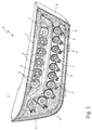
- number 1 designates as a whole an automotive light particularly suited for being fixed on the preferably rear part of the vehicle body of a car, van, lorry, motorcycle or the like, i.e. a rear automotive light.
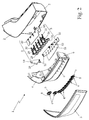
- automotive light 1 is preferably, though not necessarily, structured so as to be recessed into the rear part of the vehicle body of a car, motorcycle or similar vehicle, and basically comprises:
- the front lenticular half-shell 3 is preferably provided with two distinct transparent or semi-transparent portions, optionally also differently coloured to one another; and the automotive light 1 is preferably provided with two series of lighting assemblies which are structured to emit light when electricity powered, and are located within rear body 2 so as to be able to separately backlight the two transparent or semi-transparent portions of the front lenticular half-shell 3.
- the automotive light 1 is preferably provided with a first series of lighting assemblies 4 that are placed within the rear body 2 in a position such as to be able to backlight a first transparent or semi-transparent portion of the front half-shell 3; and with a second series of lighting assemblies 5 that are placed within the rear body 2 in a position such as to be able to backlight the second transparent or semi-transparent portion of front half-shell 3.
- Each lighting assembly 4 is therefore located underneath a corresponding sector of the first transparent or semi-transparent portion of half-shell 3 so as to be able to backlight said sector of the front lenticular half-shell 3.
- each lighting assembly 5 is located underneath a corresponding sector of the second transparent or semi-transparent portion of half-shell 3 so as to be able to backlight said sector of the front lenticular half-shell 3.
- rear body 2 is preferably made of opaque plastic material, preferably via an injection-moulding process.
- Front lenticular half-shell 3 is instead preferably made of transparent or semi-transparent plastic material, such as for example transparent or semi-transparent polycarbonate or polymethylmethacrylate (Plexiglas), also in this case preferably via an injection-moulding process.
- automotive light 1 is preferably moreover provided with a covering mask 6 made of opaque material and which is located within the rear body 2, underneath the front lenticular half-shell 3, and is structured so as to support and also hide from view part of the lighting assemblies 4 and/or 5.
- a covering mask 6 made of opaque material and which is located within the rear body 2, underneath the front lenticular half-shell 3, and is structured so as to support and also hide from view part of the lighting assemblies 4 and/or 5.
- rear body 2 also covering mask 6 is preferably made of opaque plastic material, preferably via an injection-moulding process.
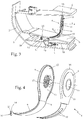
- At least one and preferably all the lighting assemblies 4 in turn comprise: an OLED-type (acronym of Organic Light-Emitting Diode) planar light source 8 which is able to emit light in a distributed manner from its own front face, and is located underneath the front lenticular half-shell 3 with its front face turned towards the inner surface of the front half-shell 3, so as to direct the emitted light towards the front lenticular half-shell 3; and a rear supporting structure 9 which is located/fixed within the rear body 2, underneath the planar light source 8, and is able to support the planar light source 8, i.e. to keep it in place underneath the front lenticular half-shell 3.
- OLED-type planar light source 8 which is able to emit light in a distributed manner from its own front face, and is located underneath the front lenticular half-shell 3 with its front face turned towards the inner surface of the front half-shell 3, so as to direct the emitted light towards the front lenticular half-shell 3
- a rear supporting structure 9
- planar light source 8 is fixed on the rear supporting structure 9 with its front face turned towards the inner surface of the front lenticular half-shell 3, and its rear face adherent to the surface of supporting structure 9.
- the lighting assembly 4 moreover also comprises a LED-type (acronym of Light Emitting Diode) concentrated light source 10 which is located within the rear body 2, spaced apart behind the planar light source 8, and is oriented so as to direct the emitted light towards the rear supporting structure 9 which, in turn, is at least partially made of photoconductive material so as to be able to channel/convey the light produced by the concentrated light source 10 up to the planar light source 8, and then to let said light come out through the planar light source 8.
- a LED-type (acronym of Light Emitting Diode) concentrated light source 10 which is located within the rear body 2, spaced apart behind the planar light source 8, and is oriented so as to direct the emitted light towards the rear supporting structure 9 which, in turn, is at least partially made of photoconductive material so as to be able to channel/convey the light produced by the concentrated light source 10 up to the planar light source 8, and then to let said light come out through the planar light source 8.
- the rear supporting structure 9 incorporates a light-guide body which is made of photoconductive material, and is structured so as to channel/convey the light produced by the concentrated light source 10 up to the planar light source 8, and then to let said light come out through the planar light source 8.
- the rear supporting structure 9 forms a light-guide body which is structured so as to receive/collect the light emitted by the concentrated light source 10 and then channel/convey said light towards the rear face of the planar light source 8; whereas planar light source 8 is structured so as to be freely crossed by the light rays r coming out from the supporting structure 9.
- the rear supporting structure 9 is entirely made of photoconductive material and is configured so that the light rays emitted by the concentrated light source 10 can freely enter into the supporting structure 9, travel within the supporting structure 9 up to the area in which the planar light source 8 is located by virtue of the same physical principles that regulate propagation of light within optical-fibre cables, and finally freely come out from the supporting structure 9 behind the planar light source 8.
- the planar light source 8 is preferably provided with at least one transparent portion 11 which is specifically structured so as to be freely crossed by the light rays r coming out from the supporting structure 9.
- transparent portion 11 is moreover located roughly in the middle of the planar light source 8.
- planar light source 8 could be structured so as to be freely crossed by the light rays r coming out from the supporting structure 9.
- the planar light source 8 is moreover fixed in immovable manner on supporting structure 9 which, in turn, is rigidly fixed to the rear body 2 and/or to the covering mask 6 so as to keep the planar light source 8 in place close to the front shell 3.
- the rear supporting structure 9 is preferably configured to keep the planar light source 8 with the front face locally substantially parallel to the inner surface of the front lenticular half-shell 3, so that the light emitted by the planar light source 8 can reach the front lenticular half-shell 3 with an angle of incidence preferably close to 90°.
- the planar light source 8 moreover is substantially circular in shape, and the transparent portion 11 is preferably located roughly at centre of the planar light source 8.
- the rear supporting structure 9 consists of an oblong light-guide body which is arranged within the rear body 2 with its distal end 13 placed close to the front lenticular half-shell 3 and with its proximal end 14 placed close to rear body 2, and is structured so as to convey the light entering from its proximal end 14 up to its distal end 13.
- the planar light source 8 is arranged with the rear face in abutment on the distal end 13 of the oblong light-guide body 9, whereas the concentrated light source 10 is arranged in abutment on or in any case directly facing the proximal end 14 of the oblong light-guide body 9, so as to direct the emitted light towards the proximal end 14.
- the concentrated light source 10 is moreover arranged underneath the covering mask 6, and the rear supporting structure 9, or rather the oblong light-guide body, engages in pass-through manner the covering mask 6 before arriving close to the front lenticular half-shell 3.
- the rear supporting structure 9 preferably consists of a ribbon-like stem made of photoconductive material and which extends within the rear body 2 from the planar light source 8 up to the concentrated light source 10, preferably following a curved line/path and preferably engaging in pass-through manner the covering mask 6, and has its distal end 13 shaped so as to accommodate the planar light source 8.
- the distal end 13 of photoconductive-material stem 9 preferably has the shape of a pan with dimensions complementary to those of the planar light source 8 so as to accommodate the planar light source 8.
- the photoconductive-material, ribbon-like stem 9 is preferably substantially C-bent, and has the distal end 13 shaped substantially like a circular pan.
- the oblong light-guide body 9, or rather the photoconductive-material stem 9, is preferably, though not necessarily, made of transparent polycarbonate, transparent polymethylmethacrylate (traditionally called Plexiglas), or of other similar transparent plastic material, preferably via an injection-moulding process.
- the oblong light-guide body 9, or rather the photoconductive-material stem 9, moreover has, at the distal end 13, a light-extracting area 15 where the outer surface of the oblong light-guide body 9 is embossed, satin-finished, and/or provided with a plenty of tiny prisms or other light-extracting elements that are specifically shaped/structured so as to deflect outwards the light rays travelling within the oblong light-guide body 9.
- the oblong light-guide body 9 moreover can be coated, obviously except for distal end 13 and proximal end 14, with a reflecting outer jacket which is able to prevent the light travelling within the oblong light-guide body 9 from coming out from the light-guide body 9 in areas other than the distal end 13.
- the planar light source 8 in turn comprises a single plate-shaped OLED diode 16 (acronym of Organic Light-Emitting Diode) which is arranged resting on the supporting structure 9, or rather on the distal end 13 of the photoconductive-material stem 9, with its own rear face turned towards the supporting structure 9 and with its own front face turned towards the front lenticular half-shell 3, so as to direct the light that coming out from its own face in a direction perpendicular to the surface of the same face, towards the front lenticular half-shell 3 preferably with an angle of incidence close to 90°.
- OLED diode 16 acronym of Organic Light-Emitting Diode
- the plate-shaped OLED diode 16 is moreover structured so as to emit light only from its front face, i.e. from the face turned towards front half-shell 3.
- the plate-shaped OLED diode 16 is substantially circular in shape and has its own rear face (i.e. the face turned towards the light-guide supporting structure 9) appropriately rendered opaque and/or mirror finished, so as to reflect the incident light towards the front face of the OLED diode 16.
- the central part of the plate-shaped OLED diode 16 is moreover overall structured so as to be transparent and preferably, though not necessarily, also photo-inactive, so as to enable the light rays r coming out from the distal end 13 of light-guide body 9 to freely pass through the OLED diode 16.
- the transparent, central part of plate-shaped OLED diode 16 thus forms the transparent portion 11 of planar light source 8.
- the plate-shaped OLED diode 16 is preferably structured so as to have a light-emitting area which is annular in shape and surrounds a transparent central area.
- the concentrated light source 10 is instead a punctiform light source, and preferably comprises a single LED diode 17 (acronym of Light Emitting Diode) which is arranged facing the light-guide supporting structure 9, so as to direct the emitted light directly into the supporting element.
- a punctiform light source preferably comprises a single LED diode 17 (acronym of Light Emitting Diode) which is arranged facing the light-guide supporting structure 9, so as to direct the emitted light directly into the supporting element.
- LED diode 17 is preferably placed in abutment on, or in any case close to, the distal end 14 of oblong light-guide body 9, so as to direct the emitted light directly into the oblong light-guide body 9.
- the lighting assembly 4 also comprises an electronic control board 18 that directly supports the concentrated light source 10, or rather the LED diode 17, and incorporates the electronic power and control circuits of the concentrated light source 10.
- the electronic control board 18 is preferably located underneath the covering mask 6, close to rear body 2.
- the electronic control board 18 furthermore incorporates also the electronic power and control circuits of the planar light source 8, and the planar light source 8, or rather the plate-shaped OLED diode 16, is electrically connected to the control board 18 via electrical leads 19 that extend on the outer surface of the rear supporting structure 9, from the area of the light-guide supporting structure 9 that houses the planar light source 8, i.e. from the distal end 13 of the oblong light-guide body 9, up to the area of the light-guide supporting structure 9 that engages the covering mask 6.
- the electronic control board 18 supports a plurality of concentrated light sources 10, each of which faces the proximal end 13 of a respective oblong light-guide body 9.
- At least one and preferably all the lighting assemblies 5 comprise: a OLED-type (acronym of Organic Light-Emitting Diode), planar light source 28 which is able to emit light in a distributed manner from its own front face, and is located underneath the front lenticular half-shell 3, with its front face turned towards the inner surface of the front half-shell 3; and a rear supporting structure 29 which is located within the rear body 2, underneath the planar light source 28, and is able to support the planar light source 28, i.e. to keep it in place underneath the front lenticular half-shell 3.
- OLED-type an organic Light-Emitting Diode
- planar light source 28 is fixed on the rear supporting structure 29 with its own front face turned towards the inner surface of the front lenticular half-shell 3 and with its own rear face adherent to the surface of the rear supporting structure 29.
- the lighting assembly 5 moreover comprises a LED-type (acronym of Light Emitting Diode) concentrated light source 30, which is located within the rear body 2, spaced apart behind the planar light source 28, and is oriented so as to direct the emitted light towards the rear supporting element 29; and the rear supporting structure 29 is at least partially made of photoconductive material so as to be able to channel/convey the light produced by the concentrated light source 30 up to the planar light source 28 and then to let it come out through the planar light source 28.
- a LED-type (acronym of Light Emitting Diode) concentrated light source 30 which is located within the rear body 2, spaced apart behind the planar light source 28, and is oriented so as to direct the emitted light towards the rear supporting element 29; and the rear supporting structure 29 is at least partially made of photoconductive material so as to be able to channel/convey the light produced by the concentrated light source 30 up to the planar light source 28 and then to let it come out through the planar light source 28.
- the rear supporting structure 29 incorporates a light-guide body which is made of photoconductive material and is structured so as to channel/convey the light produced by the concentrated light source 30 up to the planar light source 28, and then to let said light come out through the planar light source 28.
- the rear supporting structure 29 forms a light-guide body which is structured so that the light rays emitted by the concentrated light source 30 can freely enter into the supporting structure 29, travel within the supporting structure 29 up to the area in which the planar light source 28 is located by virtue of the same physical principles that regulate propagation of light within optical-fibre cables, and finally freely come out from supporting structure 29 behind the planar light source 28; whereas the planar light source 28 is structured so as to be freely crossed by the light rays coming out from the rear supporting structure 29.
- the planar light source 28 is preferably provided with at least one transparent portion 31 specifically structured so as to be freely crossed by the light rays coming out from supporting structure 29.
- the transparent portion 31 is moreover located roughly at centre of the planar light source 28.
- planar light source 28 could be structured so as to be freely crossed by the light rays coming out from supporting structure 29.
- the rear supporting structure 29 therefore incorporates a light-guide body which is structured so as to receive/collect the light emitted by the concentrated light source 30 and then channel/convey said light towards the rear face of planar light source 28.
- the planar light source 28 is moreover fixed in immovable manner on the supporting structure 29 which, in turn, is rigidly fixed to the rear body 2 and/or to the covering mask 6 so as to keep the planar light source 28 in pace close to front shell 3.
- the rear supporting structure 29 is preferably configured so as to keep the planar light source 28 with its front face locally substantially parallel to the inner surface of the front lenticular half-shell 3, so that the light emitted by the planar light source 28 can reach the front lenticular half-shell 3 with an angle of incidence preferably close to 90°.
- planar light source 28 is preferably, though not necessarily, substantially circular in shape, and transparent portion 31 is preferably located roughly at centre of the planar light source 28.
- the rear supporting structure 29 consists of an oblong light-guide body, which is placed within the rear body 2 with its own distal end 33 arranged close to the front lenticular half-shell 3 and its own proximal end 34 arranged close to the rear body 2, and is structured so as to convey the light entering from its own proximal end 34 up to its own distal end 33.
- the planar light source 28 is arranged with its rear face in abutment on the distal end 33 of the oblong light-guide body 29, whereas the concentrated light source 30 is arranged in abutment on, or in any case directly facing, the proximal end 34 of the oblong light-guide body 29, so as to direct the emitted light towards the proximal end 34.
- the rear supporting structure 29 preferably consists of a flat strip made of photoconductive material and substantially L-bent, which extends within the rear body 2 from the planar light source 28 up to the concentrated light source 30, preferably engaging in pass-through manner the covering mask 6, and has the distal end 33 shaped so as to accommodate the planar light source 28.
- the photoconductive-material flat strip 29 cantilevered projects from a supporting cross member 36 which, in turn, is preferably fixed in rigid manner on the covering mask 6, in the gap between the covering mask 6 and the rear body 2.
- the distal end 33 of the photoconductive-material flat strip 29 is moreover shaped like a pan with dimensions complementary to those of the planar light source 28, so as to accommodate the planar light source 28.
- the photoconductive-material flat strip 29 has the distal end 33 shaped like a substantially circular pan.
- the light-guide supporting structure 29 is preferably, though not necessarily, made of transparent polycarbonate, transparent polymethylmethacrylate (Plexiglas), or of other similar transparent plastic material, preferably via an injection-moulding process.
- the light-guide supporting structure 29 preferably has, at the distal end 33, a light-extracting area where the outer surface of the oblong light-guide body 29 is embossed, satin-finished and/or provided with a plenty of tiny prisms or other light-extracting elements which are suitably shaped/structured so as to deflect outwards the light rays travelling in the oblong light-guide body 29 .
- the oblong light-guide body 29 can moreover be coated, obviously except for the distal end 33 and proximal 34, by a reflecting outer jacket which is capable of preventing the light travelling within the oblong light-guide body 29 from coming out from the light-guide body 9 in areas other than the distal end 33.
- the concentrated light source 30 is preferably a punctiform light source and comprises a single LED diode (acronym of Organic Light-Emitting Diode), which is arranged facing the light-guide supporting structure 29 so as to direct the emitted light directly into the same supporting structure 29.
- the LED diode is preferably arranged in abutment on, or in any case close to, the proximal end 34 of the oblong light-guide body 29, so as to direct the emitted light into the oblong light-guide body 29 itself.
- OLED diode 38 acronym of Organic Light-Emitting Diode
- the plate-shaped OLED diode 38 is moreover structured so as to emit light only from its front face, i.e. from the face turned towards the front half-shell 3.
- the plate-shaped OLED diode 38 is substantially circular in shape and has its rear face (i.e. the face turned towards the light-guide supporting structure 29) appropriately rendered opaque and/or mirror finished, so as to reflect the incident light towards the front face of the OLED diode 38.
- the central part of the plate-shaped OLED diode 38 moreover is overall structured so as to be transparent and preferably, though not necessarily, also photo-inactive, so as to allow the light rays coming out from the distal end 33 of the oblong light-guide body 29 to freely pass through the OLED diode 38.
- the transparent central part of the plate-shaped OLED diode 38 therefore forms the transparent portion 31 of planar light source 28.
- the plate-shaped OLED diode 38 is preferably structured so as to have a light-emitting area which is annular in shape and surrounds a transparent central area.
- the lighting assembly 5 also comprises an electronic control board 40, which directly supports the concentrated light source 30, or rather the LED diode, and incorporates the electronic power and control circuits of the concentrated light source 30.
- the electronic control board 40 is moreover placed underneath the covering mask 6, i.e. in the gap between the covering mask 6 and the rear body 2.
- the electronic control board 40 is preferably fixed in rigid manner on the supporting cross member 36, on top of the proximal end 34 of the light-guide body 29.
- the electronic control board 40 moreover incorporates also the electronic power and controlo circuits of the planar light source 28, and the planar light source 28, or rather the plate-shaped OLED diode 38, is electrically connected to the control board 40 via a series of electrical leads 42 which extend on the outer surface of the light-guide body 29, from the distal end 33 of the light-guide body 29 up to the supporting cross beam 36.
- the lighting assemblies 5 preferably share the same supporting cross member 39 and the same electronic control board 40.
- the light-guide supporting structures 29 of the various lighting assemblies 5 are arranged spaced one beside the other along the supporting cross member 36.
- the electronic control board 40 instead, supports the concentrated light sources 30 of the various lighting assemblies 5, and is fixed on supporting cross member 36 so that each concentrated light source 30 faces the proximal end 34 of a corresponding oblong light-guide body 29.
- conversion of the rear supporting structure 9, 29 into a light-guide body allows to superimpose the light produced by the concentrated light source 10, 30 to the light produced by the planar light source 8, 28, thus providing new light patterns and light effects that are particularly elaborate and radically different from those of automotive lights currently available on the market.
- planar light sources 8 and 28 and the concentrated light sources 10 and 30, moreover, may be switched on in sequential manner to create dynamic light signals.
- the rear supporting structure 9, 29 enables the LED-type punctiform light source 10, 30 to be kept at a due distance from the OLED-type planar light source 8, 28, thus preventing the heat produced by the LED diodes from jeopardizing operation of the OLED diodes.
- the operating temperature of LED diodes is much higher than the maximum temperature that can be withstood by the OLED diodes.
- the rear supporting structure 9, 29 into a light-guide body also makes it possible to hide from view the electrical leads 19, 42 that have the function of powering the planar light source 8, 28.
- the rear supporting structure 9, 29, in fact, can be configured so as to allow the light to come out also in an area corresponding to the electrical leads 19, 42, i.e. also in areas other than the distal ends 13, 33.
- the plate-shaped OLED diode 16, 38 of planar light source 8, 28 could be provided with one or more through holes allowing the light rays r coming out from the distal end 13, 33 of the light-guide supporting structure 9, 29 to freely pass through the plate-shaped OLED diode 16, 38.
- the through hole or holes form the transparent portion 11, 31 of the planar light source 8, 28.
- the rear body 2 could be structured so as to be simply fixed cantilevered on the rear part of the vehicle body (not shown).
Landscapes
- Engineering & Computer Science (AREA)
- Physics & Mathematics (AREA)
- General Engineering & Computer Science (AREA)
- Optics & Photonics (AREA)
- General Physics & Mathematics (AREA)
- Microelectronics & Electronic Packaging (AREA)
- Mechanical Engineering (AREA)
- Non-Portable Lighting Devices Or Systems Thereof (AREA)
- Planar Illumination Modules (AREA)
Applications Claiming Priority (1)
| Application Number | Priority Date | Filing Date | Title |
|---|---|---|---|
| ITTV20140148 | 2014-10-13 |
Publications (2)
| Publication Number | Publication Date |
|---|---|
| EP3009301A1 true EP3009301A1 (fr) | 2016-04-20 |
| EP3009301B1 EP3009301B1 (fr) | 2022-12-21 |
Family
ID=52101521
Family Applications (1)
| Application Number | Title | Priority Date | Filing Date |
|---|---|---|---|
| EP15189660.2A Active EP3009301B1 (fr) | 2014-10-13 | 2015-10-13 | Phare automobile |
Country Status (3)
| Country | Link |
|---|---|
| EP (1) | EP3009301B1 (fr) |
| ES (1) | ES2938768T3 (fr) |
| PL (1) | PL3009301T3 (fr) |
Cited By (10)
| Publication number | Priority date | Publication date | Assignee | Title |
|---|---|---|---|---|
| CN107084354A (zh) * | 2017-04-27 | 2017-08-22 | 上海小糸车灯有限公司 | 一种oled智能组合后灯 |
| CN107415813A (zh) * | 2017-06-09 | 2017-12-01 | 广州小鹏汽车科技有限公司 | 一种电动车oled启动行驶指示系统及其控制方法 |
| CN107575831A (zh) * | 2016-06-30 | 2018-01-12 | 汽车照明意大利独资股份有限公司 | 包括具有乳光效果的发光部分的车灯 |
| FR3053763A1 (fr) * | 2016-07-07 | 2018-01-12 | Valeo Iluminacion | Support d’un moyen lumineux pour vehicule automobile |
| CN107664284A (zh) * | 2016-07-29 | 2018-02-06 | Lg电子株式会社 | 车辆用灯组件 |
| IT201600106439A1 (it) * | 2016-10-21 | 2018-04-21 | Automotive Lighting Italia Spa | Elemento di connessione elettrica per collegare un connettore elettrico multipolare a perforazione di isolante ad una scheda elettronica |
| CN109466428A (zh) * | 2018-10-19 | 2019-03-15 | 广州小鹏汽车科技有限公司 | 一种汽车和基于oled的动态指示系统及方法 |
| WO2021005331A1 (fr) * | 2019-07-11 | 2021-01-14 | Dyson Technology Limited | Ensemble feu de véhicule |
| WO2021005330A1 (fr) * | 2019-07-11 | 2021-01-14 | Dyson Technology Limited | Ensemble d'éclairage véhicule |
| US11293621B2 (en) * | 2019-12-20 | 2022-04-05 | Olsa S.P.A. | Light guide for lamps and related lamp for motor vehicles |
Citations (7)
| Publication number | Priority date | Publication date | Assignee | Title |
|---|---|---|---|---|
| EP1113216A2 (fr) * | 1999-12-27 | 2001-07-04 | Hella KG Hueck & Co. | Dispositif d' éclairage et procédé pour illuminer la partie émettant la lumière pour véhicules |
| US20090027911A1 (en) * | 2007-07-17 | 2009-01-29 | Toyoda Gosei Co., Ltd. | Vehicular lamp |
| US20090262545A1 (en) * | 2008-04-21 | 2009-10-22 | Joerg Amelung | Illumination Apparatus and Method of Producing a Planar Light Output |
| DE102009009087A1 (de) * | 2009-02-14 | 2010-08-19 | Hella Kgaa Hueck & Co. | Beleuchtungseinrichtung für ein Kraftfahrzeug |
| EP2505911A2 (fr) * | 2011-03-31 | 2012-10-03 | Valeo Vision | Dispositif optique d'un véhicule automobile assurant plusieurs fonctions. |
| EP2693105A2 (fr) * | 2012-07-31 | 2014-02-05 | Stanley Electric Co., Ltd. | Dispositif d'éclairage de véhicule |
| WO2014156668A1 (fr) * | 2013-03-27 | 2014-10-02 | 株式会社小糸製作所 | Dispositif d'éclairage pour véhicule |
-
2015
- 2015-10-13 PL PL15189660.2T patent/PL3009301T3/pl unknown
- 2015-10-13 EP EP15189660.2A patent/EP3009301B1/fr active Active
- 2015-10-13 ES ES15189660T patent/ES2938768T3/es active Active
Patent Citations (7)
| Publication number | Priority date | Publication date | Assignee | Title |
|---|---|---|---|---|
| EP1113216A2 (fr) * | 1999-12-27 | 2001-07-04 | Hella KG Hueck & Co. | Dispositif d' éclairage et procédé pour illuminer la partie émettant la lumière pour véhicules |
| US20090027911A1 (en) * | 2007-07-17 | 2009-01-29 | Toyoda Gosei Co., Ltd. | Vehicular lamp |
| US20090262545A1 (en) * | 2008-04-21 | 2009-10-22 | Joerg Amelung | Illumination Apparatus and Method of Producing a Planar Light Output |
| DE102009009087A1 (de) * | 2009-02-14 | 2010-08-19 | Hella Kgaa Hueck & Co. | Beleuchtungseinrichtung für ein Kraftfahrzeug |
| EP2505911A2 (fr) * | 2011-03-31 | 2012-10-03 | Valeo Vision | Dispositif optique d'un véhicule automobile assurant plusieurs fonctions. |
| EP2693105A2 (fr) * | 2012-07-31 | 2014-02-05 | Stanley Electric Co., Ltd. | Dispositif d'éclairage de véhicule |
| WO2014156668A1 (fr) * | 2013-03-27 | 2014-10-02 | 株式会社小糸製作所 | Dispositif d'éclairage pour véhicule |
Cited By (18)
| Publication number | Priority date | Publication date | Assignee | Title |
|---|---|---|---|---|
| CN107575831A (zh) * | 2016-06-30 | 2018-01-12 | 汽车照明意大利独资股份有限公司 | 包括具有乳光效果的发光部分的车灯 |
| JP2018018818A (ja) * | 2016-07-07 | 2018-02-01 | ヴァレオ、イルミナシオンValeo Illuminacion | 自動車の照明手段用の支持体 |
| US10358079B2 (en) | 2016-07-07 | 2019-07-23 | Valeo Iluminacion | Support for an illumination means for a motor vehicle |
| FR3053763A1 (fr) * | 2016-07-07 | 2018-01-12 | Valeo Iluminacion | Support d’un moyen lumineux pour vehicule automobile |
| CN107588392A (zh) * | 2016-07-07 | 2018-01-16 | 法雷奥照明公司 | 用于机动车的照明装置的支撑件 |
| EP3270052A1 (fr) * | 2016-07-07 | 2018-01-17 | Valeo Iluminacion | Support d'un moyen lumineux pour véhicule automobile |
| EP3290780A3 (fr) * | 2016-07-29 | 2018-04-04 | LG Electronics Inc. | Ensemble de phare pour véhicule comprenant une pluralite de modules oled |
| CN107664284A (zh) * | 2016-07-29 | 2018-02-06 | Lg电子株式会社 | 车辆用灯组件 |
| US10436412B2 (en) | 2016-07-29 | 2019-10-08 | Lg Electronics Inc. | Lamp assembly for vehicle |
| CN107664284B (zh) * | 2016-07-29 | 2020-05-05 | Zkw集团有限责任公司 | 车辆用灯组件 |
| IT201600106439A1 (it) * | 2016-10-21 | 2018-04-21 | Automotive Lighting Italia Spa | Elemento di connessione elettrica per collegare un connettore elettrico multipolare a perforazione di isolante ad una scheda elettronica |
| CN107084354A (zh) * | 2017-04-27 | 2017-08-22 | 上海小糸车灯有限公司 | 一种oled智能组合后灯 |
| CN107415813A (zh) * | 2017-06-09 | 2017-12-01 | 广州小鹏汽车科技有限公司 | 一种电动车oled启动行驶指示系统及其控制方法 |
| CN109466428A (zh) * | 2018-10-19 | 2019-03-15 | 广州小鹏汽车科技有限公司 | 一种汽车和基于oled的动态指示系统及方法 |
| WO2021005331A1 (fr) * | 2019-07-11 | 2021-01-14 | Dyson Technology Limited | Ensemble feu de véhicule |
| WO2021005330A1 (fr) * | 2019-07-11 | 2021-01-14 | Dyson Technology Limited | Ensemble d'éclairage véhicule |
| US11719410B2 (en) | 2019-07-11 | 2023-08-08 | Dyson Technology Limited | Vehicle lamp assembly |
| US11293621B2 (en) * | 2019-12-20 | 2022-04-05 | Olsa S.P.A. | Light guide for lamps and related lamp for motor vehicles |
Also Published As
| Publication number | Publication date |
|---|---|
| EP3009301B1 (fr) | 2022-12-21 |
| PL3009301T3 (pl) | 2023-05-22 |
| ES2938768T3 (es) | 2023-04-14 |
Similar Documents
| Publication | Publication Date | Title |
|---|---|---|
| EP3009301B1 (fr) | Phare automobile | |
| EP3009300B1 (fr) | Phare automobile | |
| CN106066020B (zh) | 汽车灯 | |
| EP3009734B1 (fr) | Phare automobile | |
| US7534017B2 (en) | System for providing illumination | |
| US9140422B2 (en) | Automotive rear light | |
| US20070177397A1 (en) | Lighting apparatus for vehicle | |
| CN106257136B (zh) | 车灯以及相关的制造方法 | |
| JP6325087B2 (ja) | 自動車用の照明装置 | |
| CN106195847B (zh) | 用于车辆的氛围灯 | |
| CN106016127A (zh) | 一种具有不同功能的车灯照明装置 | |
| CN108361651B (zh) | 具有装在集成有透明放大屏的支撑件上的光导的照明装置 | |
| CN112601678A (zh) | 用于机动车的照明装置 | |
| JP2014094656A (ja) | 加飾照明装置 | |
| CN107735284B (zh) | 用于车辆的侧面闪光信号灯 | |
| EP3228928B1 (fr) | Unité d'éclairage d'automobile | |
| KR101176509B1 (ko) | 간접조명 방식의 자동차 엘이디 실내등 | |
| JP6987523B2 (ja) | 車両用灯具 | |
| KR101615546B1 (ko) | 차량용 리어 컴비네이션 램프 | |
| JP2019085091A (ja) | 乗物用照明装置 | |
| JP6053600B2 (ja) | 車両用発光装置 | |
| JP2018181432A (ja) | 車両用灯具 | |
| JP2017016949A (ja) | 車輌用灯具 | |
| KR101565756B1 (ko) | 차량용 간접조명장치 | |
| JP2020087849A (ja) | 車両用灯火器 |
Legal Events
| Date | Code | Title | Description |
|---|---|---|---|
| PUAI | Public reference made under article 153(3) epc to a published international application that has entered the european phase |
Free format text: ORIGINAL CODE: 0009012 |
|
| AK | Designated contracting states |
Kind code of ref document: A1 Designated state(s): AL AT BE BG CH CY CZ DE DK EE ES FI FR GB GR HR HU IE IS IT LI LT LU LV MC MK MT NL NO PL PT RO RS SE SI SK SM TR |
|
| AX | Request for extension of the european patent |
Extension state: BA ME |
|
| 17P | Request for examination filed |
Effective date: 20161019 |
|
| RBV | Designated contracting states (corrected) |
Designated state(s): AL AT BE BG CH CY CZ DE DK EE ES FI FR GB GR HR HU IE IS IT LI LT LU LV MC MK MT NL NO PL PT RO RS SE SI SK SM TR |
|
| STAA | Information on the status of an ep patent application or granted ep patent |
Free format text: STATUS: EXAMINATION IS IN PROGRESS |
|
| 17Q | First examination report despatched |
Effective date: 20200420 |
|
| STAA | Information on the status of an ep patent application or granted ep patent |
Free format text: STATUS: EXAMINATION IS IN PROGRESS |
|
| GRAP | Despatch of communication of intention to grant a patent |
Free format text: ORIGINAL CODE: EPIDOSNIGR1 |
|
| STAA | Information on the status of an ep patent application or granted ep patent |
Free format text: STATUS: GRANT OF PATENT IS INTENDED |
|
| RIC1 | Information provided on ipc code assigned before grant |
Ipc: G02B 6/00 20060101ALI20220614BHEP Ipc: F21S 43/27 20180101ALI20220614BHEP Ipc: F21S 43/247 20180101ALI20220614BHEP Ipc: F21S 43/245 20180101ALI20220614BHEP Ipc: F21S 43/241 20180101ALI20220614BHEP Ipc: F21S 43/239 20180101ALI20220614BHEP Ipc: F21S 43/19 20180101ALI20220614BHEP Ipc: F21S 43/145 20180101ALI20220614BHEP Ipc: F21S 43/14 20180101ALI20220614BHEP Ipc: B60Q 1/26 20060101ALI20220614BHEP Ipc: B60Q 1/00 20060101AFI20220614BHEP |
|
| INTG | Intention to grant announced |
Effective date: 20220713 |
|
| GRAS | Grant fee paid |
Free format text: ORIGINAL CODE: EPIDOSNIGR3 |
|
| GRAA | (expected) grant |
Free format text: ORIGINAL CODE: 0009210 |
|
| STAA | Information on the status of an ep patent application or granted ep patent |
Free format text: STATUS: THE PATENT HAS BEEN GRANTED |
|
| RAP3 | Party data changed (applicant data changed or rights of an application transferred) |
Owner name: MARELLI AUTOMOTIVE LIGHTING ITALY S.P.A. |
|
| AK | Designated contracting states |
Kind code of ref document: B1 Designated state(s): AL AT BE BG CH CY CZ DE DK EE ES FI FR GB GR HR HU IE IS IT LI LT LU LV MC MK MT NL NO PL PT RO RS SE SI SK SM TR |
|
| REG | Reference to a national code |
Ref country code: GB Ref legal event code: FG4D |
|
| REG | Reference to a national code |
Ref country code: CH Ref legal event code: EP |
|
| REG | Reference to a national code |
Ref country code: DE Ref legal event code: R096 Ref document number: 602015081991 Country of ref document: DE |
|
| REG | Reference to a national code |
Ref country code: AT Ref legal event code: REF Ref document number: 1538872 Country of ref document: AT Kind code of ref document: T Effective date: 20230115 |
|
| REG | Reference to a national code |
Ref country code: IE Ref legal event code: FG4D |
|
| REG | Reference to a national code |
Ref country code: LT Ref legal event code: MG9D |
|
| REG | Reference to a national code |
Ref country code: ES Ref legal event code: FG2A Ref document number: 2938768 Country of ref document: ES Kind code of ref document: T3 Effective date: 20230414 |
|
| REG | Reference to a national code |
Ref country code: NL Ref legal event code: MP Effective date: 20221221 |
|
| PG25 | Lapsed in a contracting state [announced via postgrant information from national office to epo] |
Ref country code: SE Free format text: LAPSE BECAUSE OF FAILURE TO SUBMIT A TRANSLATION OF THE DESCRIPTION OR TO PAY THE FEE WITHIN THE PRESCRIBED TIME-LIMIT Effective date: 20221221 Ref country code: NO Free format text: LAPSE BECAUSE OF FAILURE TO SUBMIT A TRANSLATION OF THE DESCRIPTION OR TO PAY THE FEE WITHIN THE PRESCRIBED TIME-LIMIT Effective date: 20230321 Ref country code: LT Free format text: LAPSE BECAUSE OF FAILURE TO SUBMIT A TRANSLATION OF THE DESCRIPTION OR TO PAY THE FEE WITHIN THE PRESCRIBED TIME-LIMIT Effective date: 20221221 Ref country code: FI Free format text: LAPSE BECAUSE OF FAILURE TO SUBMIT A TRANSLATION OF THE DESCRIPTION OR TO PAY THE FEE WITHIN THE PRESCRIBED TIME-LIMIT Effective date: 20221221 |
|
| REG | Reference to a national code |
Ref country code: AT Ref legal event code: MK05 Ref document number: 1538872 Country of ref document: AT Kind code of ref document: T Effective date: 20221221 |
|
| PG25 | Lapsed in a contracting state [announced via postgrant information from national office to epo] |
Ref country code: RS Free format text: LAPSE BECAUSE OF FAILURE TO SUBMIT A TRANSLATION OF THE DESCRIPTION OR TO PAY THE FEE WITHIN THE PRESCRIBED TIME-LIMIT Effective date: 20221221 Ref country code: LV Free format text: LAPSE BECAUSE OF FAILURE TO SUBMIT A TRANSLATION OF THE DESCRIPTION OR TO PAY THE FEE WITHIN THE PRESCRIBED TIME-LIMIT Effective date: 20221221 Ref country code: HR Free format text: LAPSE BECAUSE OF FAILURE TO SUBMIT A TRANSLATION OF THE DESCRIPTION OR TO PAY THE FEE WITHIN THE PRESCRIBED TIME-LIMIT Effective date: 20221221 Ref country code: GR Free format text: LAPSE BECAUSE OF FAILURE TO SUBMIT A TRANSLATION OF THE DESCRIPTION OR TO PAY THE FEE WITHIN THE PRESCRIBED TIME-LIMIT Effective date: 20230322 |
|
| PG25 | Lapsed in a contracting state [announced via postgrant information from national office to epo] |
Ref country code: NL Free format text: LAPSE BECAUSE OF FAILURE TO SUBMIT A TRANSLATION OF THE DESCRIPTION OR TO PAY THE FEE WITHIN THE PRESCRIBED TIME-LIMIT Effective date: 20221221 |
|
| PG25 | Lapsed in a contracting state [announced via postgrant information from national office to epo] |
Ref country code: SM Free format text: LAPSE BECAUSE OF FAILURE TO SUBMIT A TRANSLATION OF THE DESCRIPTION OR TO PAY THE FEE WITHIN THE PRESCRIBED TIME-LIMIT Effective date: 20221221 Ref country code: RO Free format text: LAPSE BECAUSE OF FAILURE TO SUBMIT A TRANSLATION OF THE DESCRIPTION OR TO PAY THE FEE WITHIN THE PRESCRIBED TIME-LIMIT Effective date: 20221221 Ref country code: PT Free format text: LAPSE BECAUSE OF FAILURE TO SUBMIT A TRANSLATION OF THE DESCRIPTION OR TO PAY THE FEE WITHIN THE PRESCRIBED TIME-LIMIT Effective date: 20230421 Ref country code: EE Free format text: LAPSE BECAUSE OF FAILURE TO SUBMIT A TRANSLATION OF THE DESCRIPTION OR TO PAY THE FEE WITHIN THE PRESCRIBED TIME-LIMIT Effective date: 20221221 Ref country code: AT Free format text: LAPSE BECAUSE OF FAILURE TO SUBMIT A TRANSLATION OF THE DESCRIPTION OR TO PAY THE FEE WITHIN THE PRESCRIBED TIME-LIMIT Effective date: 20221221 |
|
| PG25 | Lapsed in a contracting state [announced via postgrant information from national office to epo] |
Ref country code: SK Free format text: LAPSE BECAUSE OF FAILURE TO SUBMIT A TRANSLATION OF THE DESCRIPTION OR TO PAY THE FEE WITHIN THE PRESCRIBED TIME-LIMIT Effective date: 20221221 Ref country code: IS Free format text: LAPSE BECAUSE OF FAILURE TO SUBMIT A TRANSLATION OF THE DESCRIPTION OR TO PAY THE FEE WITHIN THE PRESCRIBED TIME-LIMIT Effective date: 20230421 Ref country code: AL Free format text: LAPSE BECAUSE OF FAILURE TO SUBMIT A TRANSLATION OF THE DESCRIPTION OR TO PAY THE FEE WITHIN THE PRESCRIBED TIME-LIMIT Effective date: 20221221 |
|
| REG | Reference to a national code |
Ref country code: DE Ref legal event code: R097 Ref document number: 602015081991 Country of ref document: DE |
|
| PLBE | No opposition filed within time limit |
Free format text: ORIGINAL CODE: 0009261 |
|
| STAA | Information on the status of an ep patent application or granted ep patent |
Free format text: STATUS: NO OPPOSITION FILED WITHIN TIME LIMIT |
|
| PG25 | Lapsed in a contracting state [announced via postgrant information from national office to epo] |
Ref country code: DK Free format text: LAPSE BECAUSE OF FAILURE TO SUBMIT A TRANSLATION OF THE DESCRIPTION OR TO PAY THE FEE WITHIN THE PRESCRIBED TIME-LIMIT Effective date: 20221221 |
|
| PGFP | Annual fee paid to national office [announced via postgrant information from national office to epo] |
Ref country code: TR Payment date: 20230927 Year of fee payment: 9 Ref country code: IT Payment date: 20230920 Year of fee payment: 9 Ref country code: GB Payment date: 20230920 Year of fee payment: 9 Ref country code: CZ Payment date: 20230925 Year of fee payment: 9 |
|
| 26N | No opposition filed |
Effective date: 20230922 |
|
| PGFP | Annual fee paid to national office [announced via postgrant information from national office to epo] |
Ref country code: PL Payment date: 20230922 Year of fee payment: 9 Ref country code: FR Payment date: 20230920 Year of fee payment: 9 |
|
| PGFP | Annual fee paid to national office [announced via postgrant information from national office to epo] |
Ref country code: ES Payment date: 20231102 Year of fee payment: 9 |
|
| PG25 | Lapsed in a contracting state [announced via postgrant information from national office to epo] |
Ref country code: SI Free format text: LAPSE BECAUSE OF FAILURE TO SUBMIT A TRANSLATION OF THE DESCRIPTION OR TO PAY THE FEE WITHIN THE PRESCRIBED TIME-LIMIT Effective date: 20221221 |
|
| PGFP | Annual fee paid to national office [announced via postgrant information from national office to epo] |
Ref country code: DE Payment date: 20230920 Year of fee payment: 9 |