EP3004923B1 - Système de radar multifonction - Google Patents
Système de radar multifonction Download PDFInfo
- Publication number
- EP3004923B1 EP3004923B1 EP14753003.4A EP14753003A EP3004923B1 EP 3004923 B1 EP3004923 B1 EP 3004923B1 EP 14753003 A EP14753003 A EP 14753003A EP 3004923 B1 EP3004923 B1 EP 3004923B1
- Authority
- EP
- European Patent Office
- Prior art keywords
- antenna
- radar
- segment
- assembly according
- receiving
- Prior art date
- Legal status (The legal status is an assumption and is not a legal conclusion. Google has not performed a legal analysis and makes no representation as to the accuracy of the status listed.)
- Active
Links
Images


Classifications
-
- G—PHYSICS
- G01—MEASURING; TESTING
- G01S—RADIO DIRECTION-FINDING; RADIO NAVIGATION; DETERMINING DISTANCE OR VELOCITY BY USE OF RADIO WAVES; LOCATING OR PRESENCE-DETECTING BY USE OF THE REFLECTION OR RERADIATION OF RADIO WAVES; ANALOGOUS ARRANGEMENTS USING OTHER WAVES
- G01S7/00—Details of systems according to groups G01S13/00, G01S15/00, G01S17/00
- G01S7/02—Details of systems according to groups G01S13/00, G01S15/00, G01S17/00 of systems according to group G01S13/00
-
- G—PHYSICS
- G01—MEASURING; TESTING
- G01S—RADIO DIRECTION-FINDING; RADIO NAVIGATION; DETERMINING DISTANCE OR VELOCITY BY USE OF RADIO WAVES; LOCATING OR PRESENCE-DETECTING BY USE OF THE REFLECTION OR RERADIATION OF RADIO WAVES; ANALOGOUS ARRANGEMENTS USING OTHER WAVES
- G01S13/00—Systems using the reflection or reradiation of radio waves, e.g. radar systems; Analogous systems using reflection or reradiation of waves whose nature or wavelength is irrelevant or unspecified
- G01S13/02—Systems using reflection of radio waves, e.g. primary radar systems; Analogous systems
- G01S13/06—Systems determining position data of a target
- G01S13/42—Simultaneous measurement of distance and other co-ordinates
- G01S13/426—Scanning radar, e.g. 3D radar
-
- G—PHYSICS
- G01—MEASURING; TESTING
- G01S—RADIO DIRECTION-FINDING; RADIO NAVIGATION; DETERMINING DISTANCE OR VELOCITY BY USE OF RADIO WAVES; LOCATING OR PRESENCE-DETECTING BY USE OF THE REFLECTION OR RERADIATION OF RADIO WAVES; ANALOGOUS ARRANGEMENTS USING OTHER WAVES
- G01S13/00—Systems using the reflection or reradiation of radio waves, e.g. radar systems; Analogous systems using reflection or reradiation of waves whose nature or wavelength is irrelevant or unspecified
- G01S13/88—Radar or analogous systems specially adapted for specific applications
- G01S13/93—Radar or analogous systems specially adapted for specific applications for anti-collision purposes
- G01S13/933—Radar or analogous systems specially adapted for specific applications for anti-collision purposes of aircraft or spacecraft
- G01S13/935—Radar or analogous systems specially adapted for specific applications for anti-collision purposes of aircraft or spacecraft for terrain-avoidance
-
- G—PHYSICS
- G01—MEASURING; TESTING
- G01S—RADIO DIRECTION-FINDING; RADIO NAVIGATION; DETERMINING DISTANCE OR VELOCITY BY USE OF RADIO WAVES; LOCATING OR PRESENCE-DETECTING BY USE OF THE REFLECTION OR RERADIATION OF RADIO WAVES; ANALOGOUS ARRANGEMENTS USING OTHER WAVES
- G01S7/00—Details of systems according to groups G01S13/00, G01S15/00, G01S17/00
- G01S7/02—Details of systems according to groups G01S13/00, G01S15/00, G01S17/00 of systems according to group G01S13/00
- G01S7/03—Details of HF subsystems specially adapted therefor, e.g. common to transmitter and receiver
-
- H—ELECTRICITY
- H01—ELECTRIC ELEMENTS
- H01Q—ANTENNAS, i.e. RADIO AERIALS
- H01Q21/00—Antenna arrays or systems
- H01Q21/06—Arrays of individually energised antenna units similarly polarised and spaced apart
- H01Q21/08—Arrays of individually energised antenna units similarly polarised and spaced apart the units being spaced along or adjacent to a rectilinear path
-
- H—ELECTRICITY
- H01—ELECTRIC ELEMENTS
- H01Q—ANTENNAS, i.e. RADIO AERIALS
- H01Q21/00—Antenna arrays or systems
- H01Q21/28—Combinations of substantially independent non-interacting antenna units or systems
-
- H—ELECTRICITY
- H01—ELECTRIC ELEMENTS
- H01Q—ANTENNAS, i.e. RADIO AERIALS
- H01Q25/00—Antennas or antenna systems providing at least two radiating patterns
-
- H—ELECTRICITY
- H01—ELECTRIC ELEMENTS
- H01Q—ANTENNAS, i.e. RADIO AERIALS
- H01Q3/00—Arrangements for changing or varying the orientation or the shape of the directional pattern of the waves radiated from an antenna or antenna system
- H01Q3/26—Arrangements for changing or varying the orientation or the shape of the directional pattern of the waves radiated from an antenna or antenna system varying the relative phase or relative amplitude of energisation between two or more active radiating elements; varying the distribution of energy across a radiating aperture
-
- G—PHYSICS
- G01—MEASURING; TESTING
- G01S—RADIO DIRECTION-FINDING; RADIO NAVIGATION; DETERMINING DISTANCE OR VELOCITY BY USE OF RADIO WAVES; LOCATING OR PRESENCE-DETECTING BY USE OF THE REFLECTION OR RERADIATION OF RADIO WAVES; ANALOGOUS ARRANGEMENTS USING OTHER WAVES
- G01S13/00—Systems using the reflection or reradiation of radio waves, e.g. radar systems; Analogous systems using reflection or reradiation of waves whose nature or wavelength is irrelevant or unspecified
- G01S13/02—Systems using reflection of radio waves, e.g. primary radar systems; Analogous systems
- G01S2013/0236—Special technical features
- G01S2013/0245—Radar with phased array antenna
-
- G—PHYSICS
- G01—MEASURING; TESTING
- G01S—RADIO DIRECTION-FINDING; RADIO NAVIGATION; DETERMINING DISTANCE OR VELOCITY BY USE OF RADIO WAVES; LOCATING OR PRESENCE-DETECTING BY USE OF THE REFLECTION OR RERADIATION OF RADIO WAVES; ANALOGOUS ARRANGEMENTS USING OTHER WAVES
- G01S13/00—Systems using the reflection or reradiation of radio waves, e.g. radar systems; Analogous systems using reflection or reradiation of waves whose nature or wavelength is irrelevant or unspecified
- G01S13/02—Systems using reflection of radio waves, e.g. primary radar systems; Analogous systems
- G01S2013/0236—Special technical features
- G01S2013/0272—Multifunction radar
-
- G—PHYSICS
- G01—MEASURING; TESTING
- G01S—RADIO DIRECTION-FINDING; RADIO NAVIGATION; DETERMINING DISTANCE OR VELOCITY BY USE OF RADIO WAVES; LOCATING OR PRESENCE-DETECTING BY USE OF THE REFLECTION OR RERADIATION OF RADIO WAVES; ANALOGOUS ARRANGEMENTS USING OTHER WAVES
- G01S7/00—Details of systems according to groups G01S13/00, G01S15/00, G01S17/00
- G01S7/003—Transmission of data between radar, sonar or lidar systems and remote stations
- G01S7/006—Transmission of data between radar, sonar or lidar systems and remote stations using shared front-end circuitry, e.g. antennas
Definitions
- the invention relates to a radar arrangement for radiating and / or receiving at least one radar beam, which has an antenna arrangement.
- the antenna arrangement in turn has a transmission antenna device with a plurality of transmission antenna elements.
- the radar arrangement has a control device for generating control signals for the transmission antenna elements.
- the antenna arrangement has a first receiving antenna device which has a plurality of receiving antenna elements.
- the transmission antenna device has a first antenna segment and a second antenna segment, which are arranged at a distance from one another and each have a plurality of transmission antenna elements arranged along a straight line.
- Radar arrangements of the type mentioned at the outset are used in particular in aircraft or in ground surveillance radars. For example, they are used to locate other aircraft and thereby avoid collisions. Another possible application relates to scanning the surface of the earth in front of the aircraft, for example to provide the pilot with better information when flying low. Such a radar also simplifies the automation of landing systems.
- AESA radars are known for long ranges. MIMO radars with different thinned antenna arrangements are often used for imaging systems.
- EP 1 784 893 B1 It is proposed to design individual areas of an AESA grid, which is usually completely designed with transmit / receive antenna elements, with pure receive or pure transmit antenna elements.
- DE 10 2010 064 348 A1 describes a radar sensor for motor vehicles, with an antenna arrangement which can be controlled by a control device in such a way that it has a time-varying directional characteristic.
- the invention is based on the task of creating a radar arrangement of the type mentioned at the outset which can be used flexibly in a small size.
- each of the antenna segments of the radar arrangement mentioned at the beginning forms a group antenna (antenna array / antenna line) through the interaction of the transmitting antenna elements, with each of which a common radar beam can be generated and the control device for Generation of the control signals is designed such that each of the radar beams generated by the antenna segments can be pivoted separately.
- the radar arrangement according to the invention is suitable both for performing radar scanning over long distances and for scanning nearby targets with high resolution. Because only one receiving antenna device is provided, the radar arrangement requires significantly less space and is lighter in weight than the radar arrangements known hitherto for installation in aircraft, in which several independent systems are usually used. In addition, the receiving antenna device has a simple structure, so that it can be provided inexpensively. Because the transmission antenna elements of the transmission antenna device are arranged in two segments or in two lines, the radar beams generated by the segments being electronically pivotable by means of the control device by forming a group antenna, a range gain is achieved compared to a classic MIMO arrangement. Compared to a classic AESA arrangement, the structure is simplified since the transmitting antenna elements and the receiving antenna elements are completely separate.
- the antenna arrangement can have a second receiving antenna device.
- the receiving antenna devices can be arranged on opposite sides of the transmitting antenna device. This results in a particularly compact design.
- the receiving antenna devices in this case have the same orientation as the transmitting antenna device, so that the analytical requirements for the image reconstruction are reduced.
- the transmitting antenna device can have a third antenna segment.
- An additional antenna segment can increase the range and / or the resolution of the radar arrangement.
- the third antenna segment can be arranged between the first antenna segment and the second antenna segment. This results in a particularly compact design.
- At least one of the antenna segments can have several sub-segments, each of which can form a group antenna. This makes it possible to generate further independent radar beams that can be distinguished by coding or modulation, and thus to carry out several different radar tasks independently of one another.
- the control device can be designed such that each of the sub-segments can be pivoted separately.
- one of the antenna elements has two subsegments.
- Several of the transmit antenna elements can be connected to one another by an distribution network to form an antenna segment and / or a sub-segment.
- an distribution network simplifies control.
- the radar arrangement has a control device which is used to control one of the antenna segments for each of the transmit antenna elements has a signal shaping device.
- a control device which is used to control one of the antenna segments for each of the transmit antenna elements has a signal shaping device.
- the radar arrangement can have a plurality of antenna arrangements, in particular two antenna arrangements. A further increase in range and / or resolution can thereby be achieved. Depending on the orientation of the antenna arrangements, the viewing angle of the radar arrangement can also be enlarged.
- the antenna arrangements are advantageously arranged adjacent to one another. This makes it easier to combine the radar images determined by the different antenna arrangements.
- the antenna arrangements can be inclined relative to one another, in particular enclosing an angle between 185 ° and 270 ° between them. Different, frequently used viewing angles can thus be covered in a simplified manner. An angle between 90 ° and 270 ° is also conceivable.
- the antenna arrangements form an angle between them of between 120 ° and 170 °.
- Such a radar arrangement is particularly advantageous for aircraft if they require a flight and a landing radar.
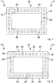
- Fig. 1 shows a first embodiment of a radar arrangement 10 with an antenna arrangement 12.
- the antenna arrangement 12 has a transmitting antenna device 14 as well as a first receiving antenna device 16 and a second receiving antenna device 18.
- the first receiving antenna device 16 and the second receiving antenna device 18 are identical in construction and are arranged on opposite sides of the transmitting antenna device 14 in such a way that the transmitting antenna device 14 lies between the first receiving antenna device 16 and the second receiving antenna device 18. As shown here, the first receiving antenna device 16 and the second receiving antenna device 18 can each be arranged adjacent to the transmitting antenna device 14.
- the transmission antenna device 14 has a multiplicity of transmission antenna elements 20 which, as shown here, can be arranged in a rectangular grid. Each of the transmission antenna elements 20 can be controlled by means of a distribution network, not shown.
- the receiving antenna devices 16, 18 each have a plurality of receiving antenna elements 22, which are arranged along a straight line.
- receiving antenna devices 16, 18 have receiving antenna elements 22 that specialize in the reception of radar signals means that complex structures, for example T / R switches, can be dispensed with.
- the provision of receiving antenna devices 16, 18 thus represents a low outlay.
- the transmission antenna elements 20 are controlled by a control device 42, as exemplarily shown in FIG 5 to 7 is shown, fed with control signals.
- the control device 42 makes it possible to pivot a radar beam generated by the transmission antenna elements 20 of the transmission antenna device 14.
- the transmission antenna elements 20 are controlled by the control device 42 in such a way that they form a group antenna.
- the transmission antenna device 14 has a first antenna segment 24 and a second antenna segment 26.
- Each of the antenna segments 24, 26 forms its own group antenna, the radar beams generated by the antenna segments 24, 26 being pivotable separately by means of the control device 42.
- the antenna segments 24, 26 are spaced apart and arranged parallel to one another.
- the first receiving antenna device 16 and the second receiving antenna device 18 are likewise spaced apart from one another and arranged parallel to one another.
- the receiving antenna device 16, 18 and the antenna segments 24, 26 are arranged such that one end of a receiving antenna device 16, 18 and one end of an antenna segment 24, 26 abut each other.
- the antenna segments 24, 26 and the receiving antenna devices 16, 18 form a frame or a parallelogram in which opposite sides in each case perform the same function in order to improve the radar performance and resolution in combination.
- the antenna segments 24, 26 each have transmission antenna elements 20 arranged along a straight line.
- the transmission antenna elements 20 are suitable for transmitting radar beams, but not for receiving radar beams.
- the antenna segments 24, 26 are therefore also not designed to receive signals.
- the manufacturing outlay similar to that in the receiving antenna devices 16, 18, can be kept low, for example by dispensing with T / R switches.
- the antenna segments 24, 26 can be produced inexpensively and compactly.
- the antenna segments 24, 26 are each divided into smaller antenna groups, which are referred to as subsegments 28, 30, 32, 34.
- the subsegments 28, 30, 32, 34 each comprise one half of the transmit antenna elements 20 of their respective antenna segment 24, 26. It is conceivable to divide the transmit antenna elements 20 in a different ratio between the subsegments 28, 30, 32, 34. It is also possible to provide more than two subsegments 28, 30, 32, 34 per antenna segment 24, 26, in particular three, four, more than three or more than four subsegments 28, 30, 32, 34.
- a third antenna segment 36 which is similar in structure to the first and / or the second antenna segment 24, 26, is provided.
- the third antenna segment 36 is between the first antenna segment 24 and the second antenna segment 26 and arranged parallel to the antenna segments 24, 26.
- the third antenna segment 36 can also be arranged remotely from the first and second antenna segments 24, 26.
- Additional antenna segments can be added if required. These further antenna segments again form group antennas whose radar beams can be pivoted separately.
- Each of the antenna segments 24, 26, 36 can be divided into several independent group antennas, which are also called subsegments 28, 30, 32, 34. If only a very simple structure is desired and a change in the assignment of the transmission antenna elements 20 to the subsegments 28, 30, 32, 34 after the manufacture can be dispensed with, it is possible to fix a corresponding distribution network firmly in the antenna segments 24, 26, 36 to integrate.
- the antenna arrangement 12 in addition to the transmitting antenna device 14 with the first antenna segment 24 and the second antenna segment 26, the antenna arrangement 12 only has a first receiving antenna device 16.
- the receiving antenna device 16 is arranged perpendicular to the antenna segments 24, 26.
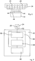
- Fig. 5 is shown by way of example for the first antenna segment 24, to connect transmit antenna elements 20 by means of a first distribution network 38 to a first sub-segment 28 and by means of a second distribution network 40 to form a second sub-segment 30.
- a control device 42 is provided to control the subsegments 28, 30. If the distribution networks 38, 40 already have facilities for beam control of the sub-segments 28, 30, for example phase shifters, the control device 42 can be carried out comparatively simply. For example, it can only be provided to control the beam direction of the subsegments 28, 30 by means of the frequency of the emitted signal.
- control device 42 controls each of the transmit antenna elements 20 of the antenna segment 24 individually, more flexibly, but also with a more complex structure.
- the control device 42 has a control stage 44 for each of the transmit antenna elements 20, which provides an output signal for controlling the transmit antenna element 20 assigned to it.
- the structure of the control device 42 is shown as an example for a transmit antenna element 20 of the first antenna segment 24.
- the control device 42 has a control computer 46, which transmits the parameters of the control signal to be generated to a signal generator 48.
- Such parameters can include, for example, frequency, phase position and modulation parameters.
- a direct digital synthesizer (direct digital synthesizer, DDS) is used as the signal generator 48.
- the signal generator 48 generates a digital description of the drive signal, which is converted by a digital-to-analog converter (DAC) 50 into the analog drive signal.
- DAC digital-to-analog converter
- This control signal is then transmitted via a distribution network 52 to the first antenna segment 24 and thus to the transmission antenna element 20.
- the signal generator 48 and the digital-to-analog converter 50 together form the control stage 44.
- control device 42 or individual parts thereof can also be accommodated in the antenna segments 24, 26, 36.
- the signal generator 48 and / or the digital-to-analog converter 50 can be arranged in the immediate vicinity of their assigned transmission antenna element 20.
- Control devices 42 have in common that they generate a control signal, typically by phase control, in such a way that the transmitting antenna elements 20, which cooperate as a group antenna, generate a radar beam that can be pivoted (beam pivoting).
- Each of the antenna segments 24, 26 or each of the sub-segments 28, 30, 32, 34 acts together as a separate group antenna and is controlled by the control device 42 as a separate group antenna.
- the radar beam generated by each antenna segment 24, 26 or subsegment 28, 30, 32, 34 can be pivoted separately and autonomously.
- the transmitting antenna elements 20 are arranged along the straight line in the individual antenna segments 24, 26 or sub-segments 28, 30, 32, 34, the individual radar beams can each be pivoted in one plane.
- the transmission antenna elements 20 can be arranged along a horizontally extending straight line, so that the beam can be swiveled along the horizontal.
- the radar arrangement 60 shown for special requirements has a first antenna arrangement 62 and a second antenna arrangement 64.
- the structure of the antenna arrangements 62, 64 corresponds in each case to one antenna arrangement 12.
- the antenna arrangements 62, 64 are arranged adjacent to one another, so that the reception antenna elements 22 of the first reception antenna devices 16 and the second reception antenna devices 18 each lie in pairs on straight lines in the same plane.
- the orientation of the receiving antenna devices 16, 18 is therefore the same in plan view in both antenna arrangements 62, 64.
- the antenna segments 24, 26 are aligned parallel to one another.
- the antenna arrangements 62, 64 form an angle a between them, here approximately 150 °. Through this different orientation, the area visible to the radar arrangement 60 can be enlarged and adapted to the respective task of the radar arrangement 60.
- the transmission antenna device 14 does not only consist of individual antenna segments 24, 26, 36, each of which has a transmission antenna elements 20 arranged along a straight line, but a field with a multiplicity of in one Has grid arranged transmission antenna elements 20.
- the subsegments 28, 30, 32, 34 do not necessarily have to comprise contiguous areas. It is also possible, for example, to assign the transmission antenna elements 20 alternately to different subsegments 28, 30, 32, 34. This allows vertical or horizontal subsegments 28, 30, 32, 34 or a checkerboard-like pattern to be generated.
- the receiving antenna devices 16, 18 have connecting means with which the receiving antenna elements 22 are connected to a receiving device (not shown).
- the receiving device analyzes the radar signals received by the receiving antenna elements 22 and obtains information therefrom about objects which reflect radar waves or radar beams.
- the receiving device can use this information to construct a radar image, for example.
- Each of the receiving antenna elements 22 can be connected to a separate input of the receiving device. Each input points to the reception of the received Signals an analog-digital converter (ADC), which provides the received signals in an digitized form to an analysis device of the receiving device.
- ADC analog-digital converter
- the receiving antenna elements 22 of one of the receiving antenna devices 16, 18 can in each case be scanned simultaneously in phase synchronization. Therefore, it is preferred if the connecting means of the receiving antenna devices 16, 18 on the route between the receiving antenna elements 22 and the receiving device ensures an identical transit time or phase shift, if possible, for all receiving antenna elements 22 on the transmission path. If deviations in the running time between the connecting means are unavoidable, these deviations can be taken into account to a certain extent in the analysis and can thus be compensated for or eliminated.
- the present radar arrangement 10, 60 can achieve long ranges with little technical effort, as well as deliver powerful imaging at close range.
- the multifunctional radar arrangement 10, 60 forms a compact radar sensor that can be used for all radar functions relevant to flight operations.
- the range and thus the imaging range of a classic MIMO radar is increased by using AESA radar components.
- the combined solution is considerably more cost-effective since the classic AESA arrangement in terms of the number of elements can be reduced to two line-like antenna segments 24, 26 and a complete 3-D image reconstruction can nevertheless be carried out by adding only two line-type reception antenna devices 16, 18 , This combines the range advantages of AESA with the advantages of the MIMO arrangement.
- the antenna arrangement 12 has a shape which is similar to a MIMO radar arrangement ( Fig. 1 ).
- the transmission antenna elements 20 of the transmission antenna device 14, which are arranged in two lines, can each be pivoted electronically one-dimensionally and thus allow a range gain compared to a conventional arrangement. Because the first receiving antenna device 16 and the second receiving antenna device 18 are arranged perpendicular to the antenna segments 24, 26 of the transmitting antenna device 14, a complete 3-D image reconstruction is possible.
- the second embodiment of the radar arrangement 10, 60 is characterized in that at least one of the antenna segments 24, 26 is divided into a plurality of sub-segments 28, 30, 32, 34, each sub-segment 28, 30, 32, 34 having its own phase center and being pivotable independently is.
- the division into subsegments 28, 30, 32, 34 can be controlled by software during operation, as a result of which the system can be dynamically adapted to different ranges and resolution requirements.
- Each of the antenna segments 24, 26 can be controlled separately, as a result of which image segments can each be processed with special requirements with regard to range and resolution.
- the third embodiment of the radar arrangement 10, 60 is in some way an intermediate form.
- the third antenna segment 36 can simultaneously increase the range as well as increase the resolution.
- a plurality of antenna arrangements 62, 64 are arranged at an angle to one another.
- an area with increased resolution overlap area of the two antenna arrangements 62, 64
- a very large imaging area without overlap of the detection areas
- the antenna arrangements 62, 64 can be operated on the same control device 42.
- One use case for this is radars for aircraft, which are to be oriented forwards in a flight mode and obliquely forwards and downwards in a landing mode.
- DAC digital-to-analog converter
- DDS Synthesizer
- the transmission antenna elements 20 of the transmission antenna device 14 can be arranged in a grid.
- the transmitting antenna device 14 can be referred to as an antenna grid device.
- the receiving antenna elements 22 can be arranged along a straight line.
- the receiving antenna devices 16, 18 can also be referred to as receiving line devices (antenna line).
- the antenna segments 24, 26, 36 can be arranged such that they each adjoin an end area of the first receiving antenna device 16 and an end area of the second receiving antenna device 18. This arrangement in the form of a rectangle is comparatively stable and easy to attach.
Landscapes
- Engineering & Computer Science (AREA)
- Radar, Positioning & Navigation (AREA)
- Remote Sensing (AREA)
- Physics & Mathematics (AREA)
- Computer Networks & Wireless Communication (AREA)
- General Physics & Mathematics (AREA)
- Aviation & Aerospace Engineering (AREA)
- Electromagnetism (AREA)
- Variable-Direction Aerials And Aerial Arrays (AREA)
- Radar Systems Or Details Thereof (AREA)
Claims (12)
- Système de radar (10, 60) pour l'émission et/ou la réception d'au moins un faisceau radar, comportant un système d'antenne (12, 62, 64), lequel comporte un dispositif d'antenne émettrice (14) doté d'une pluralité d'éléments d'antenne émettrice (20),
le système de radar (10, 60) comportant un dispositif de commande (42) pour la production de signaux de commande pour les éléments d'antenne émettrice (20) du dispositif d'antenne émettrice (14),
dans lequel le système d'antenne (12, 62, 64) comporte un premier dispositif d'antenne réceptrice (16), lequel comporte une pluralité d'éléments d'antenne réceptrice (22), dans lequel
le dispositif d'antenne émettrice (14) comporte un premier segment d'antenne (24) et un deuxième segment d'antenne (26), lesquels sont agencés à distance l'un de l'autre, dans lequel les segments d'antenne (24, 26) comportent respectivement une pluralité d'éléments d'antenne émettrice (20) agencés le long d'une droite, et dans lequel chacun des segments d'antenne (24, 26) forme respectivement une antenne-réseau par une coopération des éléments d'antenne émettrice (20), avec laquelle un faisceau radar commun respectif peut être produit,
caractérisé en ce que le dispositif de commande (42) est configuré de façon à ce que chacun des faisceaux radar produits par les segments d'antenne (24, 26) peut pivoter séparément par la fourniture des signaux de commande. - Système de radar selon la revendication 1, caractérisé en ce que le système d'antenne (12, 62, 64) comporte un deuxième dispositif d'antenne réceptrice (18).
- Système de radar selon la revendication 2, caractérisé en ce que les dispositifs d'antenne réceptrice (16, 18) sont agencés sur des côtés du dispositif d'antenne émettrice (14) opposés l'un à l'autre.
- Système de radar selon l'une des revendications ci-dessus, caractérisé en ce que le dispositif d'antenne émettrice (14) comporte un troisième segment d'antenne (36) .
- Système de radar selon la revendication 4, caractérisé en ce que le troisième segment d'antenne (36) est agencé entre le premier segment d'antenne (24) et le deuxième segment d'antenne (26).
- Système de radar selon l'une des revendications ci-dessus, caractérisé en ce qu'au moins un des segments d'antenne (24, 26, 36) comporte plusieurs sous-segments (28, 30, 32, 34), lesquels forment respectivement une antenne-réseau, dans lequel le dispositif de commande (42) est configuré de façon à ce que chacun des sous-segments (28, 30, 32, 34) peut pivoter séparément.
- Système de radar selon l'une des revendications 1 à 8, caractérisé par un dispositif de commande (42), lequel comporte un dispositif de mise en forme d'onde (48, 50) pour chacun des éléments d'antenne émettrice (20).
- Système de radar selon l'une des revendications ci-dessus, caractérisé en ce que plusieurs des éléments d'antenne émettrice (20) sont, par un réseau de distribution (38, 40), raccordés entre eux pour former un segment d'antenne et/ou un sous-segment (24, 26, 28, 30, 32, 34, 36).
- Système de radar selon l'une des revendications ci-dessus, caractérisé par au moins deux systèmes d'antenne (12, 62, 64).
- Système de radar selon la revendication 9, caractérisé en ce que les systèmes d'antenne (12, 62, 64) sont agencés contigus l'un à l'autre.
- Système de radar selon la revendication 9 ou 10, caractérisé en ce que les systèmes d'antenne (12, 62, 64) forment entre eux un angle (α) compris entre 185° et 270°.
- Système de radar selon la revendication 9 ou 10, caractérisé en ce que les systèmes d'antenne (12, 62, 64) forment entre eux un angle (α) compris entre 90° et 170°.
Applications Claiming Priority (2)
| Application Number | Priority Date | Filing Date | Title |
|---|---|---|---|
| DE102013105809.4A DE102013105809B4 (de) | 2013-06-05 | 2013-06-05 | Multifunktionale Radaranordnung |
| PCT/DE2014/000269 WO2014194877A1 (fr) | 2013-06-05 | 2014-06-02 | Système de radar multifonction |
Publications (2)
| Publication Number | Publication Date |
|---|---|
| EP3004923A1 EP3004923A1 (fr) | 2016-04-13 |
| EP3004923B1 true EP3004923B1 (fr) | 2019-12-25 |
Family
ID=51383523
Family Applications (1)
| Application Number | Title | Priority Date | Filing Date |
|---|---|---|---|
| EP14753003.4A Active EP3004923B1 (fr) | 2013-06-05 | 2014-06-02 | Système de radar multifonction |
Country Status (6)
| Country | Link |
|---|---|
| US (1) | US20160131738A1 (fr) |
| EP (1) | EP3004923B1 (fr) |
| KR (1) | KR20160018519A (fr) |
| DE (1) | DE102013105809B4 (fr) |
| IL (1) | IL242659B (fr) |
| WO (1) | WO2014194877A1 (fr) |
Families Citing this family (20)
| Publication number | Priority date | Publication date | Assignee | Title |
|---|---|---|---|---|
| CN114185042A (zh) * | 2015-09-17 | 2022-03-15 | 松下电器产业株式会社 | 雷达装置 |
| DE102016203160A1 (de) * | 2016-02-29 | 2017-08-31 | Robert Bosch Gmbh | Radarsystem, umfassend eine Antennenanordnung zum Senden und Empfangen elektromagnetischer Strahlung |
| EP3244231A1 (fr) * | 2016-05-12 | 2017-11-15 | HENSOLDT Sensors GmbH | Systeme d'antenne mimo et procede d'imagerie radar tridimensionnelle |
| EP3290856A1 (fr) * | 2016-08-31 | 2018-03-07 | Airbus Defence and Space GmbH | Missile dote d'un systeme de capteurs |
| US20180166794A1 (en) * | 2016-12-14 | 2018-06-14 | GM Global Technology Operations LLC | 2d-mimo radar antenna array geometry and design method |
| IL250253B (en) | 2017-01-24 | 2021-10-31 | Arbe Robotics Ltd | A method for separating targets and echoes from noise, in radar signals |
| IL255982A (en) | 2017-11-29 | 2018-01-31 | Arbe Robotics Ltd | Detection, mitigation and prevention of mutual interference between fixed water radars in vehicles |
| IL259190A (en) | 2018-05-07 | 2018-06-28 | Arbe Robotics Ltd | System and method for frequency hopping MIMO FMCW imaging radar |
| DE102018207686A1 (de) * | 2018-05-17 | 2019-11-21 | Robert Bosch Gmbh | MIMO-Radarsensor für Kraftfahrzeuge |
| US10838038B2 (en) * | 2018-06-20 | 2020-11-17 | GM Global Technology Operations LLC | Multi-mode radar antenna |
| IL260694A (en) | 2018-07-19 | 2019-01-31 | Arbe Robotics Ltd | Method and device for two-stage signal processing in a radar system |
| IL260696A (en) | 2018-07-19 | 2019-01-31 | Arbe Robotics Ltd | Method and device for structured self-testing of radio frequencies in a radar system |
| IL260695A (en) | 2018-07-19 | 2019-01-31 | Arbe Robotics Ltd | Method and device for eliminating waiting times in a radar system |
| IL261636A (en) * | 2018-09-05 | 2018-10-31 | Arbe Robotics Ltd | Deflected MIMO antenna array for vehicle imaging radars |
| DE102018219841A1 (de) * | 2018-11-20 | 2020-05-20 | Zf Friedrichshafen Ag | Verfahren und Steuerungseinheit für eine Radarsensorarchitektur |
| JP7224174B2 (ja) * | 2018-12-26 | 2023-02-17 | ルネサスエレクトロニクス株式会社 | 電子装置およびレーダー制御方法 |
| TWI722382B (zh) * | 2019-02-01 | 2021-03-21 | 為升電裝工業股份有限公司 | 車用雷達裝置及其系統 |
| WO2020204805A1 (fr) | 2019-04-03 | 2020-10-08 | Saab Ab | Réseau d'antennes et système de réseau à commande de phase comprenant un tel réseau d'antennes |
| IL271269A (en) | 2019-12-09 | 2021-06-30 | Arbe Robotics Ltd | Radom for a planar antenna for car radar |
| CN114910868A (zh) * | 2021-02-08 | 2022-08-16 | 华为技术有限公司 | 一种通信方法及装置 |
Family Cites Families (7)
| Publication number | Priority date | Publication date | Assignee | Title |
|---|---|---|---|---|
| US6700526B2 (en) * | 2000-09-08 | 2004-03-02 | Witten Technologies Inc. | Method and apparatus for identifying buried objects using ground penetrating radar |
| US6661375B2 (en) * | 2001-02-15 | 2003-12-09 | Roke Manor Research Limited | Beam steering in sub-arrayed antennae |
| DE102004040015B4 (de) * | 2004-08-16 | 2006-12-07 | S.M.S., Smart Microwave Sensors Gmbh | Verfahren und Vorrichtung zur Detektion eines von einer Sendeantenne ausgesandten elektromagnetischen Signals |
| US7274328B2 (en) * | 2004-08-31 | 2007-09-25 | Raytheon Company | Transmitting and receiving radio frequency signals using an active electronically scanned array |
| DE102004059915A1 (de) * | 2004-12-13 | 2006-06-14 | Robert Bosch Gmbh | Radarsystem |
| RU2374724C1 (ru) * | 2005-10-17 | 2009-11-27 | Граундпроуб Птв Лтд | Периметрическая антенная решетка радара |
| DE102010064348A1 (de) * | 2010-12-29 | 2012-07-05 | Robert Bosch Gmbh | Radarsensor für Kraftfahrzeuge |
-
2013
- 2013-06-05 DE DE102013105809.4A patent/DE102013105809B4/de not_active Expired - Fee Related
-
2014
- 2014-06-02 KR KR1020157034583A patent/KR20160018519A/ko not_active Application Discontinuation
- 2014-06-02 EP EP14753003.4A patent/EP3004923B1/fr active Active
- 2014-06-02 US US14/895,663 patent/US20160131738A1/en not_active Abandoned
- 2014-06-02 WO PCT/DE2014/000269 patent/WO2014194877A1/fr active Application Filing
-
2015
- 2015-11-18 IL IL242659A patent/IL242659B/en not_active IP Right Cessation
Non-Patent Citations (1)
| Title |
|---|
| None * |
Also Published As
| Publication number | Publication date |
|---|---|
| EP3004923A1 (fr) | 2016-04-13 |
| IL242659B (en) | 2020-02-27 |
| DE102013105809A1 (de) | 2014-12-11 |
| KR20160018519A (ko) | 2016-02-17 |
| DE102013105809B4 (de) | 2015-01-22 |
| WO2014194877A1 (fr) | 2014-12-11 |
| US20160131738A1 (en) | 2016-05-12 |
Similar Documents
| Publication | Publication Date | Title |
|---|---|---|
| EP3004923B1 (fr) | Système de radar multifonction | |
| DE102007041373B3 (de) | Synthetik-Apertur-Radarverfahren | |
| EP2753950B1 (fr) | Capteur de radar imageur à grossissement synthétique de l'ouverture d'antenne et à balayage bidimensionnel du faisceau | |
| DE112019006800T5 (de) | Antennenvorrichtung und Radarvorrichtung | |
| WO2013034281A1 (fr) | Capteur de radar imageur à lobe d'antenne étroit et zone de détection angulaire large | |
| DE112008000513T5 (de) | Elektronisch abtastendes Radarsystem und Empfangsantenne | |
| DE102006022814A1 (de) | Hochauflösendes Synthetik-Apertur-Seitenansicht-Radarsystem mittels Digital Beamforming | |
| WO2013045232A1 (fr) | Dispositif à radar et procédé pour produire une caractéristique de groupe d'un radar | |
| DE112005003573T5 (de) | Phased-Array-Radarantenne, welche eine verminderte Suchzeit hat, und Verfahren zur Benutzung derselben | |
| DE4206797B4 (de) | Verfahren zum Betreiben eines Radarantennensystems und Radarantennensystem | |
| DE2415899A1 (de) | Antennensystem, insbesondere dopplersystem | |
| DE102012224062B4 (de) | Streifenleiterantenne, Gruppenantenne und Radarvorrichtung | |
| DE112019005668T5 (de) | Antennenvorrichtung und radarsystem | |
| EP2722686B1 (fr) | Système sar interférométrique | |
| DE2716755C3 (de) | Anordnung eines elektronisch abfragbaren Impulsecho-Empfängers zur Richtungsorientierung auf einen Empfangsstrahl | |
| WO2007077062A1 (fr) | Dispositif radar | |
| DE60130396T2 (de) | Kostengünstiges Radar, insbesondere für hochauflösende Bilderzeugung | |
| EP2225582B1 (fr) | Détecteur radar monostatique multifaisceau, et procédé | |
| EP4189434A1 (fr) | Procédé pour faire fonctionner un système radar, système radar, et véhicule comprenant au moins un système radar | |
| EP2662928B1 (fr) | Dispositif d'antenne et procédé de pivotement électronique d'un faisceau radar | |
| WO2019233651A1 (fr) | Radar polarimétrique, son utilisation appropriée et son procédé à cette fin | |
| EP3564708B1 (fr) | Procédé radar à synthèse d'ouverture permettant de télédétecter la surface de la terre et dispositif radar à synthèse d'ouverture | |
| DE1766493B1 (de) | Zielverfolgungs radargeraet mit strahlnachfuehrung durch phasensteuerung der von antennenelementen abgestrahlten impulse | |
| EP2775317B1 (fr) | Procédé de fonctionnement d'un système radar avec ouverture synthétique en mode d'émission et de réception | |
| EP3217188A1 (fr) | Radar secondaire avec suppression des lobes secondaires et son procede de fonctionnement |
Legal Events
| Date | Code | Title | Description |
|---|---|---|---|
| PUAI | Public reference made under article 153(3) epc to a published international application that has entered the european phase |
Free format text: ORIGINAL CODE: 0009012 |
|
| 17P | Request for examination filed |
Effective date: 20151113 |
|
| AK | Designated contracting states |
Kind code of ref document: A1 Designated state(s): AL AT BE BG CH CY CZ DE DK EE ES FI FR GB GR HR HU IE IS IT LI LT LU LV MC MK MT NL NO PL PT RO RS SE SI SK SM TR |
|
| AX | Request for extension of the european patent |
Extension state: BA ME |
|
| DAX | Request for extension of the european patent (deleted) | ||
| GRAP | Despatch of communication of intention to grant a patent |
Free format text: ORIGINAL CODE: EPIDOSNIGR1 |
|
| STAA | Information on the status of an ep patent application or granted ep patent |
Free format text: STATUS: GRANT OF PATENT IS INTENDED |
|
| RIC1 | Information provided on ipc code assigned before grant |
Ipc: G01S 13/88 20060101AFI20190621BHEP Ipc: G01S 7/02 20060101ALI20190621BHEP Ipc: G01S 7/00 20060101ALI20190621BHEP Ipc: H01Q 21/28 20060101ALI20190621BHEP Ipc: H01Q 25/00 20060101ALI20190621BHEP Ipc: H01Q 21/08 20060101ALI20190621BHEP Ipc: G01S 13/42 20060101ALI20190621BHEP Ipc: G01S 13/94 20060101ALI20190621BHEP Ipc: G01S 7/03 20060101ALI20190621BHEP Ipc: G01S 13/02 20060101ALI20190621BHEP Ipc: H01Q 3/26 20060101ALI20190621BHEP |
|
| INTG | Intention to grant announced |
Effective date: 20190718 |
|
| GRAS | Grant fee paid |
Free format text: ORIGINAL CODE: EPIDOSNIGR3 |
|
| GRAA | (expected) grant |
Free format text: ORIGINAL CODE: 0009210 |
|
| STAA | Information on the status of an ep patent application or granted ep patent |
Free format text: STATUS: THE PATENT HAS BEEN GRANTED |
|
| AK | Designated contracting states |
Kind code of ref document: B1 Designated state(s): AL AT BE BG CH CY CZ DE DK EE ES FI FR GB GR HR HU IE IS IT LI LT LU LV MC MK MT NL NO PL PT RO RS SE SI SK SM TR |
|
| REG | Reference to a national code |
Ref country code: GB Ref legal event code: FG4D Free format text: NOT ENGLISH |
|
| RIN1 | Information on inventor provided before grant (corrected) |
Inventor name: MEUSLING, ASKOLD Inventor name: PRECHTEL, ULRICH |
|
| REG | Reference to a national code |
Ref country code: CH Ref legal event code: EP |
|
| REG | Reference to a national code |
Ref country code: DE Ref legal event code: R096 Ref document number: 502014013333 Country of ref document: DE |
|
| REG | Reference to a national code |
Ref country code: AT Ref legal event code: REF Ref document number: 1217731 Country of ref document: AT Kind code of ref document: T Effective date: 20200115 |
|
| REG | Reference to a national code |
Ref country code: IE Ref legal event code: FG4D Free format text: LANGUAGE OF EP DOCUMENT: GERMAN |
|
| REG | Reference to a national code |
Ref country code: NL Ref legal event code: MP Effective date: 20191225 |
|
| PG25 | Lapsed in a contracting state [announced via postgrant information from national office to epo] |
Ref country code: GR Free format text: LAPSE BECAUSE OF FAILURE TO SUBMIT A TRANSLATION OF THE DESCRIPTION OR TO PAY THE FEE WITHIN THE PRESCRIBED TIME-LIMIT Effective date: 20200326 Ref country code: NO Free format text: LAPSE BECAUSE OF FAILURE TO SUBMIT A TRANSLATION OF THE DESCRIPTION OR TO PAY THE FEE WITHIN THE PRESCRIBED TIME-LIMIT Effective date: 20200325 Ref country code: LT Free format text: LAPSE BECAUSE OF FAILURE TO SUBMIT A TRANSLATION OF THE DESCRIPTION OR TO PAY THE FEE WITHIN THE PRESCRIBED TIME-LIMIT Effective date: 20191225 Ref country code: LV Free format text: LAPSE BECAUSE OF FAILURE TO SUBMIT A TRANSLATION OF THE DESCRIPTION OR TO PAY THE FEE WITHIN THE PRESCRIBED TIME-LIMIT Effective date: 20191225 Ref country code: SE Free format text: LAPSE BECAUSE OF FAILURE TO SUBMIT A TRANSLATION OF THE DESCRIPTION OR TO PAY THE FEE WITHIN THE PRESCRIBED TIME-LIMIT Effective date: 20191225 Ref country code: BG Free format text: LAPSE BECAUSE OF FAILURE TO SUBMIT A TRANSLATION OF THE DESCRIPTION OR TO PAY THE FEE WITHIN THE PRESCRIBED TIME-LIMIT Effective date: 20200325 Ref country code: FI Free format text: LAPSE BECAUSE OF FAILURE TO SUBMIT A TRANSLATION OF THE DESCRIPTION OR TO PAY THE FEE WITHIN THE PRESCRIBED TIME-LIMIT Effective date: 20191225 |
|
| REG | Reference to a national code |
Ref country code: LT Ref legal event code: MG4D |
|
| PG25 | Lapsed in a contracting state [announced via postgrant information from national office to epo] |
Ref country code: RS Free format text: LAPSE BECAUSE OF FAILURE TO SUBMIT A TRANSLATION OF THE DESCRIPTION OR TO PAY THE FEE WITHIN THE PRESCRIBED TIME-LIMIT Effective date: 20191225 Ref country code: HR Free format text: LAPSE BECAUSE OF FAILURE TO SUBMIT A TRANSLATION OF THE DESCRIPTION OR TO PAY THE FEE WITHIN THE PRESCRIBED TIME-LIMIT Effective date: 20191225 |
|
| PG25 | Lapsed in a contracting state [announced via postgrant information from national office to epo] |
Ref country code: AL Free format text: LAPSE BECAUSE OF FAILURE TO SUBMIT A TRANSLATION OF THE DESCRIPTION OR TO PAY THE FEE WITHIN THE PRESCRIBED TIME-LIMIT Effective date: 20191225 |
|
| PG25 | Lapsed in a contracting state [announced via postgrant information from national office to epo] |
Ref country code: RO Free format text: LAPSE BECAUSE OF FAILURE TO SUBMIT A TRANSLATION OF THE DESCRIPTION OR TO PAY THE FEE WITHIN THE PRESCRIBED TIME-LIMIT Effective date: 20191225 Ref country code: CZ Free format text: LAPSE BECAUSE OF FAILURE TO SUBMIT A TRANSLATION OF THE DESCRIPTION OR TO PAY THE FEE WITHIN THE PRESCRIBED TIME-LIMIT Effective date: 20191225 Ref country code: PT Free format text: LAPSE BECAUSE OF FAILURE TO SUBMIT A TRANSLATION OF THE DESCRIPTION OR TO PAY THE FEE WITHIN THE PRESCRIBED TIME-LIMIT Effective date: 20200520 Ref country code: EE Free format text: LAPSE BECAUSE OF FAILURE TO SUBMIT A TRANSLATION OF THE DESCRIPTION OR TO PAY THE FEE WITHIN THE PRESCRIBED TIME-LIMIT Effective date: 20191225 Ref country code: NL Free format text: LAPSE BECAUSE OF FAILURE TO SUBMIT A TRANSLATION OF THE DESCRIPTION OR TO PAY THE FEE WITHIN THE PRESCRIBED TIME-LIMIT Effective date: 20191225 |
|
| PGFP | Annual fee paid to national office [announced via postgrant information from national office to epo] |
Ref country code: FR Payment date: 20200619 Year of fee payment: 7 Ref country code: DE Payment date: 20200618 Year of fee payment: 7 |
|
| PG25 | Lapsed in a contracting state [announced via postgrant information from national office to epo] |
Ref country code: SM Free format text: LAPSE BECAUSE OF FAILURE TO SUBMIT A TRANSLATION OF THE DESCRIPTION OR TO PAY THE FEE WITHIN THE PRESCRIBED TIME-LIMIT Effective date: 20191225 Ref country code: SK Free format text: LAPSE BECAUSE OF FAILURE TO SUBMIT A TRANSLATION OF THE DESCRIPTION OR TO PAY THE FEE WITHIN THE PRESCRIBED TIME-LIMIT Effective date: 20191225 Ref country code: IS Free format text: LAPSE BECAUSE OF FAILURE TO SUBMIT A TRANSLATION OF THE DESCRIPTION OR TO PAY THE FEE WITHIN THE PRESCRIBED TIME-LIMIT Effective date: 20200425 |
|
| PGFP | Annual fee paid to national office [announced via postgrant information from national office to epo] |
Ref country code: GB Payment date: 20200625 Year of fee payment: 7 |
|
| REG | Reference to a national code |
Ref country code: DE Ref legal event code: R097 Ref document number: 502014013333 Country of ref document: DE |
|
| PG25 | Lapsed in a contracting state [announced via postgrant information from national office to epo] |
Ref country code: DK Free format text: LAPSE BECAUSE OF FAILURE TO SUBMIT A TRANSLATION OF THE DESCRIPTION OR TO PAY THE FEE WITHIN THE PRESCRIBED TIME-LIMIT Effective date: 20191225 Ref country code: ES Free format text: LAPSE BECAUSE OF FAILURE TO SUBMIT A TRANSLATION OF THE DESCRIPTION OR TO PAY THE FEE WITHIN THE PRESCRIBED TIME-LIMIT Effective date: 20191225 |
|
| PLBE | No opposition filed within time limit |
Free format text: ORIGINAL CODE: 0009261 |
|
| STAA | Information on the status of an ep patent application or granted ep patent |
Free format text: STATUS: NO OPPOSITION FILED WITHIN TIME LIMIT |
|
| PG25 | Lapsed in a contracting state [announced via postgrant information from national office to epo] |
Ref country code: SI Free format text: LAPSE BECAUSE OF FAILURE TO SUBMIT A TRANSLATION OF THE DESCRIPTION OR TO PAY THE FEE WITHIN THE PRESCRIBED TIME-LIMIT Effective date: 20191225 |
|
| 26N | No opposition filed |
Effective date: 20200928 |
|
| PG25 | Lapsed in a contracting state [announced via postgrant information from national office to epo] |
Ref country code: IT Free format text: LAPSE BECAUSE OF FAILURE TO SUBMIT A TRANSLATION OF THE DESCRIPTION OR TO PAY THE FEE WITHIN THE PRESCRIBED TIME-LIMIT Effective date: 20191225 Ref country code: MC Free format text: LAPSE BECAUSE OF FAILURE TO SUBMIT A TRANSLATION OF THE DESCRIPTION OR TO PAY THE FEE WITHIN THE PRESCRIBED TIME-LIMIT Effective date: 20191225 |
|
| REG | Reference to a national code |
Ref country code: CH Ref legal event code: PL |
|
| PG25 | Lapsed in a contracting state [announced via postgrant information from national office to epo] |
Ref country code: PL Free format text: LAPSE BECAUSE OF FAILURE TO SUBMIT A TRANSLATION OF THE DESCRIPTION OR TO PAY THE FEE WITHIN THE PRESCRIBED TIME-LIMIT Effective date: 20191225 |
|
| PG25 | Lapsed in a contracting state [announced via postgrant information from national office to epo] |
Ref country code: LU Free format text: LAPSE BECAUSE OF NON-PAYMENT OF DUE FEES Effective date: 20200602 |
|
| REG | Reference to a national code |
Ref country code: BE Ref legal event code: MM Effective date: 20200630 |
|
| PG25 | Lapsed in a contracting state [announced via postgrant information from national office to epo] |
Ref country code: LI Free format text: LAPSE BECAUSE OF NON-PAYMENT OF DUE FEES Effective date: 20200630 Ref country code: IE Free format text: LAPSE BECAUSE OF NON-PAYMENT OF DUE FEES Effective date: 20200602 Ref country code: CH Free format text: LAPSE BECAUSE OF NON-PAYMENT OF DUE FEES Effective date: 20200630 |
|
| PG25 | Lapsed in a contracting state [announced via postgrant information from national office to epo] |
Ref country code: BE Free format text: LAPSE BECAUSE OF NON-PAYMENT OF DUE FEES Effective date: 20200630 |
|
| REG | Reference to a national code |
Ref country code: AT Ref legal event code: MM01 Ref document number: 1217731 Country of ref document: AT Kind code of ref document: T Effective date: 20200602 |
|
| PG25 | Lapsed in a contracting state [announced via postgrant information from national office to epo] |
Ref country code: AT Free format text: LAPSE BECAUSE OF NON-PAYMENT OF DUE FEES Effective date: 20200602 |
|
| REG | Reference to a national code |
Ref country code: DE Ref legal event code: R119 Ref document number: 502014013333 Country of ref document: DE |
|
| GBPC | Gb: european patent ceased through non-payment of renewal fee |
Effective date: 20210602 |
|
| PG25 | Lapsed in a contracting state [announced via postgrant information from national office to epo] |
Ref country code: GB Free format text: LAPSE BECAUSE OF NON-PAYMENT OF DUE FEES Effective date: 20210602 Ref country code: DE Free format text: LAPSE BECAUSE OF NON-PAYMENT OF DUE FEES Effective date: 20220101 |
|
| PG25 | Lapsed in a contracting state [announced via postgrant information from national office to epo] |
Ref country code: TR Free format text: LAPSE BECAUSE OF FAILURE TO SUBMIT A TRANSLATION OF THE DESCRIPTION OR TO PAY THE FEE WITHIN THE PRESCRIBED TIME-LIMIT Effective date: 20191225 Ref country code: MT Free format text: LAPSE BECAUSE OF FAILURE TO SUBMIT A TRANSLATION OF THE DESCRIPTION OR TO PAY THE FEE WITHIN THE PRESCRIBED TIME-LIMIT Effective date: 20191225 Ref country code: FR Free format text: LAPSE BECAUSE OF NON-PAYMENT OF DUE FEES Effective date: 20210630 Ref country code: CY Free format text: LAPSE BECAUSE OF FAILURE TO SUBMIT A TRANSLATION OF THE DESCRIPTION OR TO PAY THE FEE WITHIN THE PRESCRIBED TIME-LIMIT Effective date: 20191225 |
|
| PG25 | Lapsed in a contracting state [announced via postgrant information from national office to epo] |
Ref country code: MK Free format text: LAPSE BECAUSE OF FAILURE TO SUBMIT A TRANSLATION OF THE DESCRIPTION OR TO PAY THE FEE WITHIN THE PRESCRIBED TIME-LIMIT Effective date: 20191225 |