EP2662928B1 - Dispositif d'antenne et procédé de pivotement électronique d'un faisceau radar - Google Patents
Dispositif d'antenne et procédé de pivotement électronique d'un faisceau radar Download PDFInfo
- Publication number
- EP2662928B1 EP2662928B1 EP13166682.8A EP13166682A EP2662928B1 EP 2662928 B1 EP2662928 B1 EP 2662928B1 EP 13166682 A EP13166682 A EP 13166682A EP 2662928 B1 EP2662928 B1 EP 2662928B1
- Authority
- EP
- European Patent Office
- Prior art keywords
- radar
- antenna
- feed
- individual
- signal
- Prior art date
- Legal status (The legal status is an assumption and is not a legal conclusion. Google has not performed a legal analysis and makes no representation as to the accuracy of the status listed.)
- Active
Links
Images


Classifications
-
- H—ELECTRICITY
- H01—ELECTRIC ELEMENTS
- H01Q—ANTENNAS, i.e. RADIO AERIALS
- H01Q3/00—Arrangements for changing or varying the orientation or the shape of the directional pattern of the waves radiated from an antenna or antenna system
- H01Q3/26—Arrangements for changing or varying the orientation or the shape of the directional pattern of the waves radiated from an antenna or antenna system varying the relative phase or relative amplitude of energisation between two or more active radiating elements; varying the distribution of energy across a radiating aperture
- H01Q3/30—Arrangements for changing or varying the orientation or the shape of the directional pattern of the waves radiated from an antenna or antenna system varying the relative phase or relative amplitude of energisation between two or more active radiating elements; varying the distribution of energy across a radiating aperture varying the relative phase between the radiating elements of an array
- H01Q3/34—Arrangements for changing or varying the orientation or the shape of the directional pattern of the waves radiated from an antenna or antenna system varying the relative phase or relative amplitude of energisation between two or more active radiating elements; varying the distribution of energy across a radiating aperture varying the relative phase between the radiating elements of an array by electrical means
-
- G—PHYSICS
- G01—MEASURING; TESTING
- G01S—RADIO DIRECTION-FINDING; RADIO NAVIGATION; DETERMINING DISTANCE OR VELOCITY BY USE OF RADIO WAVES; LOCATING OR PRESENCE-DETECTING BY USE OF THE REFLECTION OR RERADIATION OF RADIO WAVES; ANALOGOUS ARRANGEMENTS USING OTHER WAVES
- G01S13/00—Systems using the reflection or reradiation of radio waves, e.g. radar systems; Analogous systems using reflection or reradiation of waves whose nature or wavelength is irrelevant or unspecified
- G01S13/02—Systems using reflection of radio waves, e.g. primary radar systems; Analogous systems
- G01S13/06—Systems determining position data of a target
- G01S13/42—Simultaneous measurement of distance and other co-ordinates
- G01S13/426—Scanning radar, e.g. 3D radar
-
- G—PHYSICS
- G01—MEASURING; TESTING
- G01S—RADIO DIRECTION-FINDING; RADIO NAVIGATION; DETERMINING DISTANCE OR VELOCITY BY USE OF RADIO WAVES; LOCATING OR PRESENCE-DETECTING BY USE OF THE REFLECTION OR RERADIATION OF RADIO WAVES; ANALOGOUS ARRANGEMENTS USING OTHER WAVES
- G01S13/00—Systems using the reflection or reradiation of radio waves, e.g. radar systems; Analogous systems using reflection or reradiation of waves whose nature or wavelength is irrelevant or unspecified
- G01S13/88—Radar or analogous systems specially adapted for specific applications
- G01S13/93—Radar or analogous systems specially adapted for specific applications for anti-collision purposes
- G01S13/933—Radar or analogous systems specially adapted for specific applications for anti-collision purposes of aircraft or spacecraft
- G01S13/935—Radar or analogous systems specially adapted for specific applications for anti-collision purposes of aircraft or spacecraft for terrain-avoidance
-
- G—PHYSICS
- G01—MEASURING; TESTING
- G01S—RADIO DIRECTION-FINDING; RADIO NAVIGATION; DETERMINING DISTANCE OR VELOCITY BY USE OF RADIO WAVES; LOCATING OR PRESENCE-DETECTING BY USE OF THE REFLECTION OR RERADIATION OF RADIO WAVES; ANALOGOUS ARRANGEMENTS USING OTHER WAVES
- G01S7/00—Details of systems according to groups G01S13/00, G01S15/00, G01S17/00
- G01S7/02—Details of systems according to groups G01S13/00, G01S15/00, G01S17/00 of systems according to group G01S13/00
- G01S7/03—Details of HF subsystems specially adapted therefor, e.g. common to transmitter and receiver
-
- G—PHYSICS
- G01—MEASURING; TESTING
- G01S—RADIO DIRECTION-FINDING; RADIO NAVIGATION; DETERMINING DISTANCE OR VELOCITY BY USE OF RADIO WAVES; LOCATING OR PRESENCE-DETECTING BY USE OF THE REFLECTION OR RERADIATION OF RADIO WAVES; ANALOGOUS ARRANGEMENTS USING OTHER WAVES
- G01S7/00—Details of systems according to groups G01S13/00, G01S15/00, G01S17/00
- G01S7/02—Details of systems according to groups G01S13/00, G01S15/00, G01S17/00 of systems according to group G01S13/00
- G01S7/04—Display arrangements
- G01S7/06—Cathode-ray tube displays or other two dimensional or three-dimensional displays
- G01S7/062—Cathode-ray tube displays or other two dimensional or three-dimensional displays in which different colours are used
-
- H—ELECTRICITY
- H01—ELECTRIC ELEMENTS
- H01Q—ANTENNAS, i.e. RADIO AERIALS
- H01Q1/00—Details of, or arrangements associated with, antennas
- H01Q1/27—Adaptation for use in or on movable bodies
- H01Q1/28—Adaptation for use in or on aircraft, missiles, satellites, or balloons
-
- H—ELECTRICITY
- H01—ELECTRIC ELEMENTS
- H01Q—ANTENNAS, i.e. RADIO AERIALS
- H01Q3/00—Arrangements for changing or varying the orientation or the shape of the directional pattern of the waves radiated from an antenna or antenna system
- H01Q3/22—Arrangements for changing or varying the orientation or the shape of the directional pattern of the waves radiated from an antenna or antenna system varying the orientation in accordance with variation of frequency of radiated wave
-
- G—PHYSICS
- G01—MEASURING; TESTING
- G01S—RADIO DIRECTION-FINDING; RADIO NAVIGATION; DETERMINING DISTANCE OR VELOCITY BY USE OF RADIO WAVES; LOCATING OR PRESENCE-DETECTING BY USE OF THE REFLECTION OR RERADIATION OF RADIO WAVES; ANALOGOUS ARRANGEMENTS USING OTHER WAVES
- G01S13/00—Systems using the reflection or reradiation of radio waves, e.g. radar systems; Analogous systems using reflection or reradiation of waves whose nature or wavelength is irrelevant or unspecified
- G01S13/02—Systems using reflection of radio waves, e.g. primary radar systems; Analogous systems
- G01S2013/0236—Special technical features
- G01S2013/0245—Radar with phased array antenna
Definitions
- the application relates to an antenna device for a radar sensor, which has a plurality of individual antenna devices that interact by means of interference for generating and / or receiving a radar beam at a predetermined transmission and / or reception angle.
- the individual antenna devices are exposed to a radar signal, and are arranged so that a first transmission and / or reception angle of the radar beam can be determined by an analog beam shaping in the form of a frequency of the radar signal.
- the application relates to a method for electronically panning a radar beam, wherein the radar beam is electronically pivotable and is generated by interference of radar signals emitted by a plurality of individual antennas.
- the individual antenna devices are supplied from a supply device by means of supply lines with a supply signal, wherein an analog beam shaping is used for pivoting the radar beam in a first pivot plane.
- the application also relates to a radar sensor with such an antenna device, with which such a method is executable, as well as an aircraft with such a radar sensor.
- Antenna devices of the aforementioned type are used as radar sensors in radar devices for detecting surface structures of solid or liquid materials. This application is particularly interesting for use as obstacle radar in aircraft.
- the high-frequency electromagnetic waves commonly referred to as radar waves
- they are bundled by means of interference and beamforming by the shape of the antennas radiating them in such a way that their propagation is restricted to a comparatively small solid angle. In a sense, a radar beam is generated with which objects can be scanned.
- radar signals received by the antenna devices can be linked in such a way that, by means of the phase shift of the received radar signals, the signals whose propagation direction has a specific angle to the antenna device can be filtered out. This angle to which the reception is restricted is called the reception lobe.
- the antenna of the sensor can either be moved mechanically in two dimensions, ie horizontally and vertically, or the radar beam can be pivoted electronically.
- Known imaging obstacle radars such as those sold by the company Honeywell are limited due to the use of lower frequencies in their image resolution and geometrically comparatively large, since in particular the antenna devices used have a large spatial extent due to the wavelength of the radar waves used. Radar systems that use higher frequency ranges to achieve higher image resolution (e.g., Rockwell Collins Sandblasters) have mechanically tilted antennas, which also require a large amount of space.
- US 3438035 A is a radar antenna having a plurality of arranged in a grid antenna elements, known.
- One of this radar antenna emitted radar beam is pivotable in the elevation by means of setting a frequency.
- US 3646559 A discloses a radar antenna in which two independently operating modes, namely a frequency controlled mode and a phased mode, can be used independently for the rotation of the radar beam. Particular attention is paid to reducing as much as possible the interaction between the two modes. One component of this is to use different frequency ranges for the two modes.
- WO 00/51202 A1 It is known to use a beam-shaping antenna for satellite communication. In order to be able to maintain communication with multiple satellites seamlessly, even if one of the satellites moves out of the visible range, a second antenna constructed in the same way is provided.
- a radar sensor is to be created, whose applicability is improved in aircraft.
- the antenna device has the advantage that the analog beam shaping by changing the frequency with known power supply devices for radar antennas is easy to carry out.
- the ability to pivot a radar beam in a first direction by analog beam shaping and in a second direction by digital beam shaping, can be dispensed with complex mechanical means for pivoting the entire radar sensor.
- Suitable feeding devices can be realized with low space requirements and low weight compared to the mechanical pivoting.
- such an antenna device also allows the use of high frequencies for the generated radar beam.
- Radar antenna feeders have the ability to quickly and accurately change the frequency of the radar signal they provide. As a result, the transmission and / or reception angle can be changed efficiently with comparatively simply constructed and known supply devices.
- the individual antenna devices By arranging the individual antenna devices in antenna groups, wherein a plurality of antenna groups can be arranged side by side, it is in particular possible to produce a field of individual antenna devices, which are arranged in a rectangular grid. In such a rectangular grid, the effect of phase shifts on the direction of the generated radar beam is particularly easy to determine.
- the supply device can be connected by supply lines to the individual antennas, wherein the supply lines to the individual antennas have different lengths.
- a transit time of the radar signals in the feed line influences a phase position of the radar signals at the end of the feed line, that is, in the individual antennas.
- a single feed line may be provided for connection to the feed device, wherein the feed device is configured to provide a separate feed signal for each antenna array.
- the feeding device for feeding the antenna groups can be designed such that a phase shift between the radar signals of the individual antenna groups is adjustable.
- the method according to claim 5 has the advantage that no complex devices are necessary for its implementation, so that it is also applicable in devices with low expansion and low weight.
- one aspect of the invention also relates to a radar sensor having an antenna device according to the invention, with which the method according to the invention can be carried out.
- Such a radar sensor is particularly suitable for use in an aircraft, so that an aspect of the invention further relates to an aircraft with such a radar sensor.
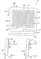
- An antenna device 10 for a radar sensor has a frame 12 to which an antenna module 14 is attached.
- the antenna module 14 is designed to emit electromagnetic waves, in particular high-frequency radar signals.
- the antenna module 14 can be used in particular for the emission of electromagnetic waves having a frequency between 76 GHz and 81 GHz.
- the antenna module 14 has a plurality of individual antenna devices 16, which are arranged in a planar grid.
- the grid is rectangular, wherein a first dimension 90 and a second dimension 92 of the grid are perpendicular to each other.
- the individual antenna devices 16 are arranged along the dimensions 90, 92 in rows.
- the individual antenna devices 16 are arranged essentially in an antenna plane 22 in which the dimensions 90, 92 are located.
- Individual antenna devices 16, which lie along the dimension 90 along a straight line one behind the other, are each combined to form an antenna group 24.
- a feed device 18 is provided, which is connected by leads 20 to the antenna module 14.
- the antenna module 14 has a distribution network, not shown, with which the radar signals are distributed to the individual antenna devices 16.
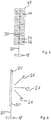
- Fig. 2 shows a side view of one of the antenna groups 24.
- the radar signal, with which the individual antenna devices 16 of the antenna array 24 are fed, has on its arrival at the individual antenna devices 16 each have a phase position.
- a bundling effect is produced, which results macroscopically in a radar beam 26 which is emitted at a transmitting and / or receiving angle 28 to the antenna plane 22. If the phase position for all radar signals, with which the individual antenna devices 16 are fed, is identical, the angle 28 is 90 °.
- Fig. 3 the radar beam 26 is shown, which results when the phase angle of the individual antenna devices 16 is varied.
- the angle 28 is less than 90 ° in this case.
- the angle 28 can be between 0 ° and 180 °.
- the radar beam 26 can be pivoted by means of interference only in one plane.
- a pivoting of the radar beam 26 in a first pivot plane 94 is possible, which corresponds to a change of the first angle 28 . If the phase position of the antenna groups 24 is changed relative to one another, interference can again be achieved by pivoting the radar beam 26 in a second pivoting plane 96, which results in a change of a second transmission and / or reception angle 29 (see FIG 8 and 9 ) corresponds.
- a feeding device 18, which has to generate its own radar signal for each of the individual antenna devices 16 for a field thus formed of many individual antenna devices 16, is extremely complicated, since it must comprise a multiplicity of outputs which each provide a radar signal with a very precise phase position.
- FIG. 5 an antenna array 24 is shown with individual antenna devices 16 and a distribution network 30 connecting the individual antenna devices 16.
- the supply line 20 of the distribution network is connected to the supply device 18 connected. If the feed device 18 now feeds a radar signal via the feed line 20, this is distributed from the feed line 20 to the distribution network 30.
- the radar signal requires a certain transit time in order to pass from the supply device 18 through the supply line to the distribution network 30. Likewise, the radar signal takes some time to travel in the distribution network. As a result, the beginning of the radar signal reaches the individual antenna device 32 first because it is closest to the feed line 20 and thus also to the feed device 18.
- the radar signal at the first individual antenna device 32 already has a different phase position than at its beginning. This phase shift from one single antenna device 16, 32, 34 to the next continues for each of the single antenna devices 16. As a result, by interference in the electromagnetic waves emitted by the individual antenna devices 16, 32, 34, it is possible to pivot the radar beam 26.
- the magnitude of the phase shift is determined by the transit time required by the radar signal to pass from one individual antenna device 16, 32, 34 to the next. If the transit time between the individual antenna devices 16, 32, 34 corresponds, for example, to an integer multiple of the cycle duration of the injected radar signal, then the phase position of the individual antenna devices 16, 32, 34 is identical and the radar beam 26 is radiated perpendicularly.
- the frequency of the radar signal By changing the frequency of the radar signal simultaneously changes the period of the injected radar signal, so that the transit time between the individual antenna devices 16, 32, 34 corresponds to a different phase shift depending on the frequency.
- the angle in which the Radar beam 26 is pivoted, is only dependent on the frequency of the injected radar signal.
- the radar beam 26 can therefore be at the top as it is in Fig. 6 is shown, by the frequency of the injected radar signal is changed.
- the feed device 18 must adjust for a pivoting of the radar beam 26 in the first pivot plane 94 in this way only the frequency of the injected radar signal. This is a form of analogue beamforming.
- the ability to adjust the frequency of the injected radar signal is already part of most radar systems today. Additional complex circuits or structures are not necessary.
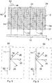
- FIG. 7 An arrangement of a plurality of antenna groups 24 next to each other is in Fig. 7 shown.
- Each of the antenna groups 24 has a feed line 20, with which it is connected to a feed device 18.
- the feed device 18 feeds the antenna groups 24 each with phase-shifted radar signals, so that the radar beam is pivoted in the second pivot plane 96.
- the feed device 18 feeds the antenna groups 24 each with radar signals of a specific frequency, so that is pivoted by the effect described above, the radar beam in the first pivot plane 94 depending on the frequency of the radar signal.
- the pivoting in the first pivot plane 94 (FIG. Fig. 9 ) by the fed frequency and the pivoting in the second pivoting plane 96 (FIG. Fig. 8 ) determined by the phase shift of the injected radar signals.
- the radar beam 26 can thus be pivoted completely electronically. Devices that mechanically rotate the antenna device 10 or the antenna module 14 are no longer necessary.
- Fig. 10 shows a display device 100 which is part of an obstacle radar.
- the display device 100 has display elements 102 which are arranged in a rectangular grid.
- the obstacle radar uses the antenna device 10 to scan an area in front of the antenna device 10 with a radar beam 26 for obstacles.
- the radar beam 26 is swiveled in a certain angular range in the two pivot planes 94, 96 and the information about obstacles detected in the display elements 102 is displayed.
- each row of the display elements 102 is assigned a frequency of the feed device 18, and in each case one column of the display elements 102 is assigned a phase shift between the antenna groups 24.
- the power supply 18 generates for each display element 102 its associated frequency and phase shift combination.
- Each of the display elements 102 may present information in different ways, such as color, intensity, or brightness.
- the obstacle radar can determine, for example, a distance to an obstacle. The closer the obstacle is, the brighter the display element 102 becomes. Thus, similar to a camera image in the visible range, a distance map for obstacles results in the field of vision of the obstacle radar.
- each of the display elements 102 may represent pictograms or text.
- the antenna device 10 is broadband, that is, in a large frequency band, in this embodiment, 76 GHz to 81 GHz, usable. However, only a narrowband radar signal is generated by the feed device 18.
- Aperture mapping is still possible.
- the radiating elements that is, the individual antenna devices 16, 32, 34, can thereby be varied so that they emit different powers.
- Aperture allows beam shaping in a spatial direction needed for practical applications.
- beam shaping may mean that the width of the radar beam 26 (emission lobe) can be influenced and that the radiation in other directions is suppressed.
- the spacing of the individual antenna devices 16, 32, 34 must not become too great. The maximum distance depends, among other things, on the frequency of the radar signal used.
- the individual antenna devices 16, 32, 34 are arranged planar and in one plane.
- a single antenna device 16, 32, 34 has a substrate with a metallization on the substrate and a completely metallized area under the substrate. The substrate itself is located between the metal layers.
- multilayer substrates may also be useful.
- Digital beamforming can be effected during transmission so that the phase shift is generated digitally and then transmitted over equally long lines to the antennas.
- a received signal can be over the transmit lines of the same length and then convert analog / digital. Then it can then be processed digitally and so a virtual beam control of the receiving lobe can be achieved.
- the distances between the individual antenna devices 16, 32, 34 are identical in each case in a dimension 90, 92.
- the distances of the individual antenna devices 16, 32, 34 can be varied without affecting the ability to electronically pivot the radar beam 26.
- the geometry of the arrangement of the individual antenna devices 16, 32, 34 is only to be considered in the selection of the frequencies to be used.
- the frequency-controlled analog beam shaping can, as described above, be effected by different physical line lengths, but also by different electrical line lengths. If the factors causing the different electrical line length are variable, the analog beam shaping during use of the antenna device 10 can be influenced. As a result, for example, the frequencies used for scanning can be varied.
- the individual antenna devices 16 are shown so that they are all the same size and have the same spatial orientation. For different applications, however, it may be desirable for the individual antenna devices 16 to have different sizes and / or a different spatial orientation. By such variations of size and / or spatial orientation it is possible to polarize the radiated radar signal or to achieve extended broadband of the antenna.
- the individual antenna devices 16 can also be arranged offset from each other.
- the dimensions 90,92 are therefore not necessarily perpendicular to each other.
- the radar beam 26 emitted by the individual antenna devices 16, 32, 34 is radiated at a different angle 28 than 90 °, if the phase position is identical for all radar signals with which the individual antenna devices 16 are fed.
- the analog beam shaping is effected in the exemplary embodiment in that the feed lines 20 to the individual antenna devices 16 each have different lengths.
- the feed device 18 must provide only one feed signal for each antenna group 24.
- the analog beamforming is then performed by the distribution network 30.
- phase shift which is generated analogously, can be performed by the supply device 18 in this case.
- the line lengths of the leads 20 within the feed device 18 could be made physically and / or electrically changeable. It is also possible to generate the supply signals by means of direct digital synthesis.
- Mechanically tilted antennas are only partially suitable for integration on flying platforms.
- the electrical beam tilting in two dimensions is limited in the higher frequency range due to geometric and technological limitations and usually associated with high overall costs of the system.
- the two-dimensional electrical beam tilting is achieved according to the invention by the narrowband use of a broadband radar system at different frequencies.
- a first spatial direction for example, horizontal
- the beam is conventionally electronically controlled with either analog or digital beam sweep.
- a second spatial direction for example vertically
- special planar antenna and supply structures cause the antenna beam to be rotated in different directions during operation of the radar system at different frequencies.
Landscapes
- Engineering & Computer Science (AREA)
- Remote Sensing (AREA)
- Radar, Positioning & Navigation (AREA)
- Physics & Mathematics (AREA)
- General Physics & Mathematics (AREA)
- Computer Networks & Wireless Communication (AREA)
- Aviation & Aerospace Engineering (AREA)
- Astronomy & Astrophysics (AREA)
- Electromagnetism (AREA)
- Variable-Direction Aerials And Aerial Arrays (AREA)
- Radar Systems Or Details Thereof (AREA)
Claims (7)
- Dispositif d'antenne (10) pour un capteur radar, comprenant une pluralité d'installations d'antennes individuelles (16) coopérant par interférence pour produire un faisceau radar dans un angle de transmission et/ou un angle de réception prédéterminé,
dans lequel un signal radar est appliqué sur les installations d'antennes individuelles (16) et
dans lequel les installations d'antennes individuelles (16) sont disposées de manière qu'un premier angle de transmission et/ou de réception (28) du faisceau radar (26) est déterminé par une formation de faisceau analogue et le premier angle de transmission et/ou de réception (28) est déterminable par une fréquence du signal radar,
dans lequel un deuxième angle de transmission et/ou de réception (29) du faisceau radar (26) est déterminé par une formation de faisceau digitale, dans lequel les installations d'antennes individuelles (16) sont groupées comme des groupes d'antennes (24),
dans lequel une pluralité de groupes d'antennes (24) sont juxtaposées, dans lequel un dispositif d'alimentation (18) pour la génération et l'alimentation du signal radar est prévu,
dans lequel le dispositif d'alimentation (18) pour la génération de signaux d'alimentation est agencé pour la réalisation d'une formation de faisceau analogue dans un premier plan de pivotement (94) par l'alimentation des groupes d'antennes (24) respectives en signaux radar d'une fréquence déterminée et pour la réalisation d'une formation de faisceau digitale dans un deuxième plan de pivotement (96) par l'alimentation des groupes d'antennes (24) respectives en signaux radar décalés,
dans lequel le dispositif d'alimentation (18) est réalisé de manière qu'en cas de changement de la position de phase des installations d'antennes individuelles (16) dans un groupe d'antennes (24) le faisceau radar (26) peut être pivoté dans le premier plan de pivotement (94) tel qu'un premier angle de transmission et/ou de réception (28) peut être modifié, et qu'en cas de changement de la position de phase des groupes d'antennes (24) les uns par rapport aux autres le faisceau radar (26) peut être pivoté dans le deuxième plan de pivotement (96) tel que le deuxième angle de transmission et/ou de réception (29) peut être changé,
le dispositif d'alimentation (18) étant réalisé de manière qu'en cas de changement de la fréquence du signal radar alimenté le faisceau radar (26) peut être pivoté dans le premier plan de pivotement (28). - Dispositif d'antenne selon la revendication 1, caractérisé en ce que le dispositif d'alimentation (18) est relié aux antennes individuelles (16) par des conducteurs (20), lesdits conducteurs (20) aux antennes individuelles (16) présentant des longueurs électriques différentes.
- Dispositif d'antenne selon l'une des revendications précédentes, caractérisé en ce que pour chaque groupe d'antennes (24) est prévu un conducteur individuel (20) pour la connexion au dispositif d'alimentation (18), ledit dispositif d'alimentation (18) étant conçu pour fournir un signal d'alimentation séparé pour chaque groupe d'antennes (24).
- Dispositif d'antenne selon la revendication 3, caractérisé en ce que le dispositif d'alimentation (18) pour alimenter les groupes d'antennes (24) est réalisé de telle sorte qu'une déphasage entre les signaux radar des groupes d'antennes (24) individuelles soit réglable.
- Procédé pour générer un faisceau radar (26), dans lequel le faisceau radar (26) peut être pivoté de manière électronique et est généré par l'interférence des ondes radar émises de plusieurs installations d'antennes individuelles (16) et dans lequel les installations d'antennes individuelles (16) sont alimentées par des conducteurs (20) en un signal d'alimentation à partir d'un dispositif d'alimentation (18), le procédé comprenant les étapes suivantes:a) utilisation d'une formation de faisceau analogue pour le pivotement du faisceau radar (26) dans un premier plan de pivotement (94), variation d'une fréquence du signal d'alimentation pour la formation de faisceau analogue;b) utilisation de plusieurs groupes d'antennes (24), chacun d'eux comportant une pluralité d'installations d'antennes individuelles (16),c) alimentation des groupes d'antennes (24) en un signal d'alimentation, le signal d'alimentation des groupes d'antennes (24) présentant respectivement une déphasage par rapport aux signaux d'alimentation des autres groupes d'antennes (24) de sorte que le faisceau radar (26) est pivoté dans un deuxième plan de pivotement (96), en utilisant une formation de faisceau digitale pour l'exécution de l'étape c).
- Capteur radar avec un dispositif d'antenne selon l'une des revendications 1 à 4, permettant une exécution du procédé selon la revendication 5.
- Aéronef comprenant un capteur radar selon la revendication 6.
Applications Claiming Priority (1)
| Application Number | Priority Date | Filing Date | Title |
|---|---|---|---|
| DE102012104037A DE102012104037A1 (de) | 2012-05-08 | 2012-05-08 | Antennenvorrichtung und Verfahren zum elektronischen Schwenken eines Radarstrahls |
Publications (3)
| Publication Number | Publication Date |
|---|---|
| EP2662928A2 EP2662928A2 (fr) | 2013-11-13 |
| EP2662928A3 EP2662928A3 (fr) | 2014-06-25 |
| EP2662928B1 true EP2662928B1 (fr) | 2018-08-15 |
Family
ID=48288919
Family Applications (1)
| Application Number | Title | Priority Date | Filing Date |
|---|---|---|---|
| EP13166682.8A Active EP2662928B1 (fr) | 2012-05-08 | 2013-05-06 | Dispositif d'antenne et procédé de pivotement électronique d'un faisceau radar |
Country Status (3)
| Country | Link |
|---|---|
| US (1) | US9431704B2 (fr) |
| EP (1) | EP2662928B1 (fr) |
| DE (1) | DE102012104037A1 (fr) |
Families Citing this family (1)
| Publication number | Priority date | Publication date | Assignee | Title |
|---|---|---|---|---|
| WO2017121477A1 (fr) * | 2016-01-14 | 2017-07-20 | Huawei Technologies Co., Ltd. | Dispositif de réseau d'antennes en phase |
Family Cites Families (16)
| Publication number | Priority date | Publication date | Assignee | Title |
|---|---|---|---|---|
| US3438035A (en) * | 1966-08-08 | 1969-04-08 | Itt | Pencil beam frequency/phase scanning system |
| US3646559A (en) * | 1968-01-15 | 1972-02-29 | North American Rockwell | Phase and frequency scanned antenna |
| JP2545958B2 (ja) * | 1988-12-16 | 1996-10-23 | 三菱電機株式会社 | ディジタルビームフォーミングレーダ |
| US5239301A (en) * | 1989-05-26 | 1993-08-24 | The United States Of America As Represented By The Secretary Of The Air Force | Phase/phase/frequency-scan radar apparatus |
| US5544525A (en) * | 1994-08-10 | 1996-08-13 | Radian Corporation | Atmospheric remote sensing instrument system |
| US6184827B1 (en) * | 1999-02-26 | 2001-02-06 | Motorola, Inc. | Low cost beam steering planar array antenna |
| US6184825B1 (en) * | 1999-06-29 | 2001-02-06 | Trw Inc. | Method and apparatus for radio frequency beam pointing |
| DE10345314A1 (de) * | 2003-09-30 | 2005-04-14 | Robert Bosch Gmbh | Vorrichtung sowie Verfahren zum Abstrahlen und/oder zum Empfangen von elektromagnetischer Strahlung |
| US20070210959A1 (en) * | 2006-03-07 | 2007-09-13 | Massachusetts Institute Of Technology | Multi-beam tile array module for phased array systems |
| GB0816978D0 (en) * | 2008-09-17 | 2008-10-22 | Qinetiq Ltd | Security portal |
| EP2392048B1 (fr) * | 2009-02-02 | 2018-10-31 | Commonwealth Scientific and Industrial Research Organisation | Réseau d'antennes adaptatif hybride |
| JP5620757B2 (ja) * | 2010-09-01 | 2014-11-05 | 株式会社豊田中央研究所 | レーダ装置 |
| KR101303626B1 (ko) * | 2011-01-06 | 2013-09-11 | 서강대학교산학협력단 | 피사체를 진단하는 진단시스템, 피사체에 대한 진단영상을 제공하는 의료영상시스템 및 피사체에 대한 진단영상을 표시하는 방법 |
| US9124361B2 (en) * | 2011-10-06 | 2015-09-01 | Raytheon Company | Scalable, analog monopulse network |
| US9444534B2 (en) * | 2012-02-06 | 2016-09-13 | Samsung Electronics Co., Ltd. | Apparatus and method for low complexity spatial division multiple access in a millimeter wave mobile communication system |
| US8874047B2 (en) * | 2012-03-19 | 2014-10-28 | Intel Mobile Communications GmbH | Agile and adaptive transmitter-receiver isolation |
-
2012
- 2012-05-08 DE DE102012104037A patent/DE102012104037A1/de not_active Withdrawn
-
2013
- 2013-05-06 EP EP13166682.8A patent/EP2662928B1/fr active Active
- 2013-05-07 US US13/888,909 patent/US9431704B2/en active Active
Non-Patent Citations (1)
| Title |
|---|
| None * |
Also Published As
| Publication number | Publication date |
|---|---|
| US20130300603A1 (en) | 2013-11-14 |
| DE102012104037A1 (de) | 2013-11-14 |
| US9431704B2 (en) | 2016-08-30 |
| EP2662928A2 (fr) | 2013-11-13 |
| EP2662928A3 (fr) | 2014-06-25 |
Similar Documents
| Publication | Publication Date | Title |
|---|---|---|
| DE102013105809B4 (de) | Multifunktionale Radaranordnung | |
| DE102010002910B4 (de) | Antennenarray und Radarvorrichtung | |
| DE102005062031B4 (de) | Hochauflösende Synthetik-Apertur-Radarvorrichtung | |
| EP2191297B1 (fr) | Procédé faisant appel à un radar à synthèse d'ouverture | |
| DE112019006801T5 (de) | Antennenvorrichtung und Radarvorrichtung | |
| EP2735055B1 (fr) | Antenne à réflecteur pour un radar à ouverture synthétique | |
| WO2013045232A1 (fr) | Dispositif à radar et procédé pour produire une caractéristique de groupe d'un radar | |
| DE102011113018A1 (de) | Abbildender Radarsensor mit schmaler Antennenkeule und weitem Winkel-Detektionsbereich | |
| EP2965382B1 (fr) | Système d'antennes à caractéristique directionnelle variable | |
| DE102019120460A1 (de) | Wanderwellen-bildverteiler für ein hochauflösendes radarsystem | |
| WO2009033541A1 (fr) | Systèmes à retard temps réel comprenant une antenne réseau permettant d'obtenir une caractéristique de rayonnement spatialement variable pour des impulsions ultra large bande de puissance très élevée | |
| DE69625949T2 (de) | Gruppenantennenvorrichtung | |
| EP2616840A1 (fr) | Capteur radar pour véhicules à moteur, notamment capteur lca | |
| DE102017113255A1 (de) | Kreuzförmiges Antennenarray | |
| DE3042456A1 (de) | Antenne mit einer einrichtung zur drehung der polarisationsebene | |
| WO2004023601A1 (fr) | Dispositif de calibrage pour un reseau d'antennes commutable et procede pour faire fonctionner ce dispositif | |
| DE4206797B4 (de) | Verfahren zum Betreiben eines Radarantennensystems und Radarantennensystem | |
| DE2822845C2 (de) | Gruppenantenne mit elektronisch gesteuerter Strahlschwenkung | |
| EP2662928B1 (fr) | Dispositif d'antenne et procédé de pivotement électronique d'un faisceau radar | |
| DE112019005668T5 (de) | Antennenvorrichtung und radarsystem | |
| DE3317693A1 (de) | Mikrostrip-flaechenantenne mit (gamma)-speisung und verfahren zur frequenz- und/oder temperaturkompensation dafuer | |
| DE102012224062B4 (de) | Streifenleiterantenne, Gruppenantenne und Radarvorrichtung | |
| EP3641056B1 (fr) | Source hpem, véhicule et procédé | |
| DE2040018B2 (de) | Raumabtastverfahren mittels eines elevational schwenkbaren Radarantennen-Richtdiagramms und Radarsystem zu dessen Durchführung | |
| DE102018111123A1 (de) | Antennen-Array mit Sende- und Empfangsantennenelementen und Verfahren zum Betreiben eines Antennen-Arrays |
Legal Events
| Date | Code | Title | Description |
|---|---|---|---|
| PUAI | Public reference made under article 153(3) epc to a published international application that has entered the european phase |
Free format text: ORIGINAL CODE: 0009012 |
|
| AK | Designated contracting states |
Kind code of ref document: A2 Designated state(s): AL AT BE BG CH CY CZ DE DK EE ES FI FR GB GR HR HU IE IS IT LI LT LU LV MC MK MT NL NO PL PT RO RS SE SI SK SM TR |
|
| AX | Request for extension of the european patent |
Extension state: BA ME |
|
| PUAL | Search report despatched |
Free format text: ORIGINAL CODE: 0009013 |
|
| AK | Designated contracting states |
Kind code of ref document: A3 Designated state(s): AL AT BE BG CH CY CZ DE DK EE ES FI FR GB GR HR HU IE IS IT LI LT LU LV MC MK MT NL NO PL PT RO RS SE SI SK SM TR |
|
| AX | Request for extension of the european patent |
Extension state: BA ME |
|
| RIC1 | Information provided on ipc code assigned before grant |
Ipc: H01Q 21/00 20060101ALI20140516BHEP Ipc: H01Q 21/22 20060101ALI20140516BHEP Ipc: H01Q 1/28 20060101AFI20140516BHEP Ipc: H01Q 3/30 20060101ALI20140516BHEP Ipc: H01Q 3/22 20060101ALI20140516BHEP Ipc: H01Q 21/06 20060101ALI20140516BHEP |
|
| RAP1 | Party data changed (applicant data changed or rights of an application transferred) |
Owner name: AIRBUS DEFENCE AND SPACE GMBH |
|
| 17P | Request for examination filed |
Effective date: 20141223 |
|
| RBV | Designated contracting states (corrected) |
Designated state(s): AL AT BE BG CH CY CZ DE DK EE ES FI FR GB GR HR HU IE IS IT LI LT LU LV MC MK MT NL NO PL PT RO RS SE SI SK SM TR |
|
| STAA | Information on the status of an ep patent application or granted ep patent |
Free format text: STATUS: EXAMINATION IS IN PROGRESS |
|
| 17Q | First examination report despatched |
Effective date: 20170104 |
|
| GRAP | Despatch of communication of intention to grant a patent |
Free format text: ORIGINAL CODE: EPIDOSNIGR1 |
|
| STAA | Information on the status of an ep patent application or granted ep patent |
Free format text: STATUS: GRANT OF PATENT IS INTENDED |
|
| INTG | Intention to grant announced |
Effective date: 20180403 |
|
| RIN1 | Information on inventor provided before grant (corrected) |
Inventor name: SCHULTE, BENEDIKT Inventor name: ZIEGLER, VOLKER |
|
| GRAS | Grant fee paid |
Free format text: ORIGINAL CODE: EPIDOSNIGR3 |
|
| GRAA | (expected) grant |
Free format text: ORIGINAL CODE: 0009210 |
|
| STAA | Information on the status of an ep patent application or granted ep patent |
Free format text: STATUS: THE PATENT HAS BEEN GRANTED |
|
| AK | Designated contracting states |
Kind code of ref document: B1 Designated state(s): AL AT BE BG CH CY CZ DE DK EE ES FI FR GB GR HR HU IE IS IT LI LT LU LV MC MK MT NL NO PL PT RO RS SE SI SK SM TR |
|
| REG | Reference to a national code |
Ref country code: CH Ref legal event code: EP Ref country code: GB Ref legal event code: FG4D Free format text: NOT ENGLISH Ref country code: AT Ref legal event code: REF Ref document number: 1030835 Country of ref document: AT Kind code of ref document: T Effective date: 20180815 |
|
| REG | Reference to a national code |
Ref country code: IE Ref legal event code: FG4D Free format text: LANGUAGE OF EP DOCUMENT: GERMAN |
|
| REG | Reference to a national code |
Ref country code: DE Ref legal event code: R096 Ref document number: 502013010842 Country of ref document: DE |
|
| REG | Reference to a national code |
Ref country code: NL Ref legal event code: MP Effective date: 20180815 |
|
| REG | Reference to a national code |
Ref country code: LT Ref legal event code: MG4D |
|
| PG25 | Lapsed in a contracting state [announced via postgrant information from national office to epo] |
Ref country code: LT Free format text: LAPSE BECAUSE OF FAILURE TO SUBMIT A TRANSLATION OF THE DESCRIPTION OR TO PAY THE FEE WITHIN THE PRESCRIBED TIME-LIMIT Effective date: 20180815 Ref country code: RS Free format text: LAPSE BECAUSE OF FAILURE TO SUBMIT A TRANSLATION OF THE DESCRIPTION OR TO PAY THE FEE WITHIN THE PRESCRIBED TIME-LIMIT Effective date: 20180815 Ref country code: IS Free format text: LAPSE BECAUSE OF FAILURE TO SUBMIT A TRANSLATION OF THE DESCRIPTION OR TO PAY THE FEE WITHIN THE PRESCRIBED TIME-LIMIT Effective date: 20181215 Ref country code: SE Free format text: LAPSE BECAUSE OF FAILURE TO SUBMIT A TRANSLATION OF THE DESCRIPTION OR TO PAY THE FEE WITHIN THE PRESCRIBED TIME-LIMIT Effective date: 20180815 Ref country code: FI Free format text: LAPSE BECAUSE OF FAILURE TO SUBMIT A TRANSLATION OF THE DESCRIPTION OR TO PAY THE FEE WITHIN THE PRESCRIBED TIME-LIMIT Effective date: 20180815 Ref country code: GR Free format text: LAPSE BECAUSE OF FAILURE TO SUBMIT A TRANSLATION OF THE DESCRIPTION OR TO PAY THE FEE WITHIN THE PRESCRIBED TIME-LIMIT Effective date: 20181116 Ref country code: NO Free format text: LAPSE BECAUSE OF FAILURE TO SUBMIT A TRANSLATION OF THE DESCRIPTION OR TO PAY THE FEE WITHIN THE PRESCRIBED TIME-LIMIT Effective date: 20181115 Ref country code: BG Free format text: LAPSE BECAUSE OF FAILURE TO SUBMIT A TRANSLATION OF THE DESCRIPTION OR TO PAY THE FEE WITHIN THE PRESCRIBED TIME-LIMIT Effective date: 20181115 Ref country code: NL Free format text: LAPSE BECAUSE OF FAILURE TO SUBMIT A TRANSLATION OF THE DESCRIPTION OR TO PAY THE FEE WITHIN THE PRESCRIBED TIME-LIMIT Effective date: 20180815 |
|
| PG25 | Lapsed in a contracting state [announced via postgrant information from national office to epo] |
Ref country code: LV Free format text: LAPSE BECAUSE OF FAILURE TO SUBMIT A TRANSLATION OF THE DESCRIPTION OR TO PAY THE FEE WITHIN THE PRESCRIBED TIME-LIMIT Effective date: 20180815 Ref country code: HR Free format text: LAPSE BECAUSE OF FAILURE TO SUBMIT A TRANSLATION OF THE DESCRIPTION OR TO PAY THE FEE WITHIN THE PRESCRIBED TIME-LIMIT Effective date: 20180815 Ref country code: AL Free format text: LAPSE BECAUSE OF FAILURE TO SUBMIT A TRANSLATION OF THE DESCRIPTION OR TO PAY THE FEE WITHIN THE PRESCRIBED TIME-LIMIT Effective date: 20180815 |
|
| PG25 | Lapsed in a contracting state [announced via postgrant information from national office to epo] |
Ref country code: IT Free format text: LAPSE BECAUSE OF FAILURE TO SUBMIT A TRANSLATION OF THE DESCRIPTION OR TO PAY THE FEE WITHIN THE PRESCRIBED TIME-LIMIT Effective date: 20180815 Ref country code: ES Free format text: LAPSE BECAUSE OF FAILURE TO SUBMIT A TRANSLATION OF THE DESCRIPTION OR TO PAY THE FEE WITHIN THE PRESCRIBED TIME-LIMIT Effective date: 20180815 Ref country code: RO Free format text: LAPSE BECAUSE OF FAILURE TO SUBMIT A TRANSLATION OF THE DESCRIPTION OR TO PAY THE FEE WITHIN THE PRESCRIBED TIME-LIMIT Effective date: 20180815 Ref country code: CZ Free format text: LAPSE BECAUSE OF FAILURE TO SUBMIT A TRANSLATION OF THE DESCRIPTION OR TO PAY THE FEE WITHIN THE PRESCRIBED TIME-LIMIT Effective date: 20180815 Ref country code: EE Free format text: LAPSE BECAUSE OF FAILURE TO SUBMIT A TRANSLATION OF THE DESCRIPTION OR TO PAY THE FEE WITHIN THE PRESCRIBED TIME-LIMIT Effective date: 20180815 Ref country code: PL Free format text: LAPSE BECAUSE OF FAILURE TO SUBMIT A TRANSLATION OF THE DESCRIPTION OR TO PAY THE FEE WITHIN THE PRESCRIBED TIME-LIMIT Effective date: 20180815 |
|
| REG | Reference to a national code |
Ref country code: DE Ref legal event code: R097 Ref document number: 502013010842 Country of ref document: DE |
|
| PG25 | Lapsed in a contracting state [announced via postgrant information from national office to epo] |
Ref country code: DK Free format text: LAPSE BECAUSE OF FAILURE TO SUBMIT A TRANSLATION OF THE DESCRIPTION OR TO PAY THE FEE WITHIN THE PRESCRIBED TIME-LIMIT Effective date: 20180815 Ref country code: SK Free format text: LAPSE BECAUSE OF FAILURE TO SUBMIT A TRANSLATION OF THE DESCRIPTION OR TO PAY THE FEE WITHIN THE PRESCRIBED TIME-LIMIT Effective date: 20180815 Ref country code: SM Free format text: LAPSE BECAUSE OF FAILURE TO SUBMIT A TRANSLATION OF THE DESCRIPTION OR TO PAY THE FEE WITHIN THE PRESCRIBED TIME-LIMIT Effective date: 20180815 |
|
| PLBE | No opposition filed within time limit |
Free format text: ORIGINAL CODE: 0009261 |
|
| STAA | Information on the status of an ep patent application or granted ep patent |
Free format text: STATUS: NO OPPOSITION FILED WITHIN TIME LIMIT |
|
| 26N | No opposition filed |
Effective date: 20190516 |
|
| PG25 | Lapsed in a contracting state [announced via postgrant information from national office to epo] |
Ref country code: SI Free format text: LAPSE BECAUSE OF FAILURE TO SUBMIT A TRANSLATION OF THE DESCRIPTION OR TO PAY THE FEE WITHIN THE PRESCRIBED TIME-LIMIT Effective date: 20180815 |
|
| REG | Reference to a national code |
Ref country code: CH Ref legal event code: PL |
|
| PG25 | Lapsed in a contracting state [announced via postgrant information from national office to epo] |
Ref country code: MC Free format text: LAPSE BECAUSE OF FAILURE TO SUBMIT A TRANSLATION OF THE DESCRIPTION OR TO PAY THE FEE WITHIN THE PRESCRIBED TIME-LIMIT Effective date: 20180815 Ref country code: CH Free format text: LAPSE BECAUSE OF NON-PAYMENT OF DUE FEES Effective date: 20190531 Ref country code: LI Free format text: LAPSE BECAUSE OF NON-PAYMENT OF DUE FEES Effective date: 20190531 |
|
| REG | Reference to a national code |
Ref country code: BE Ref legal event code: MM Effective date: 20190531 |
|
| PG25 | Lapsed in a contracting state [announced via postgrant information from national office to epo] |
Ref country code: LU Free format text: LAPSE BECAUSE OF NON-PAYMENT OF DUE FEES Effective date: 20190506 |
|
| PG25 | Lapsed in a contracting state [announced via postgrant information from national office to epo] |
Ref country code: TR Free format text: LAPSE BECAUSE OF FAILURE TO SUBMIT A TRANSLATION OF THE DESCRIPTION OR TO PAY THE FEE WITHIN THE PRESCRIBED TIME-LIMIT Effective date: 20180815 |
|
| PG25 | Lapsed in a contracting state [announced via postgrant information from national office to epo] |
Ref country code: IE Free format text: LAPSE BECAUSE OF NON-PAYMENT OF DUE FEES Effective date: 20190506 |
|
| PG25 | Lapsed in a contracting state [announced via postgrant information from national office to epo] |
Ref country code: BE Free format text: LAPSE BECAUSE OF NON-PAYMENT OF DUE FEES Effective date: 20190531 |
|
| PG25 | Lapsed in a contracting state [announced via postgrant information from national office to epo] |
Ref country code: PT Free format text: LAPSE BECAUSE OF FAILURE TO SUBMIT A TRANSLATION OF THE DESCRIPTION OR TO PAY THE FEE WITHIN THE PRESCRIBED TIME-LIMIT Effective date: 20181215 |
|
| REG | Reference to a national code |
Ref country code: AT Ref legal event code: MM01 Ref document number: 1030835 Country of ref document: AT Kind code of ref document: T Effective date: 20190506 |
|
| PG25 | Lapsed in a contracting state [announced via postgrant information from national office to epo] |
Ref country code: AT Free format text: LAPSE BECAUSE OF NON-PAYMENT OF DUE FEES Effective date: 20190506 |
|
| PG25 | Lapsed in a contracting state [announced via postgrant information from national office to epo] |
Ref country code: CY Free format text: LAPSE BECAUSE OF FAILURE TO SUBMIT A TRANSLATION OF THE DESCRIPTION OR TO PAY THE FEE WITHIN THE PRESCRIBED TIME-LIMIT Effective date: 20180815 |
|
| PG25 | Lapsed in a contracting state [announced via postgrant information from national office to epo] |
Ref country code: HU Free format text: LAPSE BECAUSE OF FAILURE TO SUBMIT A TRANSLATION OF THE DESCRIPTION OR TO PAY THE FEE WITHIN THE PRESCRIBED TIME-LIMIT; INVALID AB INITIO Effective date: 20130506 Ref country code: MT Free format text: LAPSE BECAUSE OF FAILURE TO SUBMIT A TRANSLATION OF THE DESCRIPTION OR TO PAY THE FEE WITHIN THE PRESCRIBED TIME-LIMIT Effective date: 20180815 |
|
| PG25 | Lapsed in a contracting state [announced via postgrant information from national office to epo] |
Ref country code: MK Free format text: LAPSE BECAUSE OF FAILURE TO SUBMIT A TRANSLATION OF THE DESCRIPTION OR TO PAY THE FEE WITHIN THE PRESCRIBED TIME-LIMIT Effective date: 20180815 |
|
| PGFP | Annual fee paid to national office [announced via postgrant information from national office to epo] |
Ref country code: FR Payment date: 20230526 Year of fee payment: 11 Ref country code: DE Payment date: 20230519 Year of fee payment: 11 |
|
| PGFP | Annual fee paid to national office [announced via postgrant information from national office to epo] |
Ref country code: GB Payment date: 20230524 Year of fee payment: 11 |