EP3244231A1 - Systeme d'antenne mimo et procede d'imagerie radar tridimensionnelle - Google Patents
Systeme d'antenne mimo et procede d'imagerie radar tridimensionnelle Download PDFInfo
- Publication number
- EP3244231A1 EP3244231A1 EP16001077.3A EP16001077A EP3244231A1 EP 3244231 A1 EP3244231 A1 EP 3244231A1 EP 16001077 A EP16001077 A EP 16001077A EP 3244231 A1 EP3244231 A1 EP 3244231A1
- Authority
- EP
- European Patent Office
- Prior art keywords
- antenna
- antennas
- transmit
- antenna group
- line
- Prior art date
- Legal status (The legal status is an assumption and is not a legal conclusion. Google has not performed a legal analysis and makes no representation as to the accuracy of the status listed.)
- Pending
Links
Images


Classifications
-
- G—PHYSICS
- G01—MEASURING; TESTING
- G01S—RADIO DIRECTION-FINDING; RADIO NAVIGATION; DETERMINING DISTANCE OR VELOCITY BY USE OF RADIO WAVES; LOCATING OR PRESENCE-DETECTING BY USE OF THE REFLECTION OR RERADIATION OF RADIO WAVES; ANALOGOUS ARRANGEMENTS USING OTHER WAVES
- G01S13/00—Systems using the reflection or reradiation of radio waves, e.g. radar systems; Analogous systems using reflection or reradiation of waves whose nature or wavelength is irrelevant or unspecified
- G01S13/88—Radar or analogous systems specially adapted for specific applications
- G01S13/89—Radar or analogous systems specially adapted for specific applications for mapping or imaging
-
- G—PHYSICS
- G01—MEASURING; TESTING
- G01S—RADIO DIRECTION-FINDING; RADIO NAVIGATION; DETERMINING DISTANCE OR VELOCITY BY USE OF RADIO WAVES; LOCATING OR PRESENCE-DETECTING BY USE OF THE REFLECTION OR RERADIATION OF RADIO WAVES; ANALOGOUS ARRANGEMENTS USING OTHER WAVES
- G01S13/00—Systems using the reflection or reradiation of radio waves, e.g. radar systems; Analogous systems using reflection or reradiation of waves whose nature or wavelength is irrelevant or unspecified
- G01S13/87—Combinations of radar systems, e.g. primary radar and secondary radar
- G01S13/878—Combination of several spaced transmitters or receivers of known location for determining the position of a transponder or a reflector
-
- H—ELECTRICITY
- H01—ELECTRIC ELEMENTS
- H01Q—ANTENNAS, i.e. RADIO AERIALS
- H01Q1/00—Details of, or arrangements associated with, antennas
- H01Q1/52—Means for reducing coupling between antennas; Means for reducing coupling between an antenna and another structure
- H01Q1/521—Means for reducing coupling between antennas; Means for reducing coupling between an antenna and another structure reducing the coupling between adjacent antennas
- H01Q1/525—Means for reducing coupling between antennas; Means for reducing coupling between an antenna and another structure reducing the coupling between adjacent antennas between emitting and receiving antennas
-
- H—ELECTRICITY
- H01—ELECTRIC ELEMENTS
- H01Q—ANTENNAS, i.e. RADIO AERIALS
- H01Q21/00—Antenna arrays or systems
- H01Q21/06—Arrays of individually energised antenna units similarly polarised and spaced apart
- H01Q21/061—Two dimensional planar arrays
- H01Q21/065—Patch antenna array
Definitions
- the present invention relates to an antenna array, a method for three-dimensional (3D) radar imaging, and more particularly to multiple-in-multiple-out (MIMO) antenna arrays for high-resolution 3D radar imaging.
- MIMO multiple-in-multiple-out
- radar sensors are characterized by their all-weather capability, penetration properties and day and night operational capability and are therefore used today for a wide variety of applications in the areas of target detection, imaging and remote sensing.
- an inherent disadvantage compared to optical sensors is a lower angular resolution, which is determined by the size of the antenna area (aperture) and the wavelength used.
- imaging radar e.g. the environment shown in the form of a two- or three-dimensional course of the received backscatter performance.
- the representation of small objects requires a high resolution in order to (i) achieve a high degree of detail and (ii) to increase the contrast with respect to the background (clutter).
- the disadvantage of the lower transverse resolution can be (partially) compensated by intelligent algorithms.
- functionality from the radio frequency (RF) range is shifted to the digital domain.
- MIMO multiple-in multiple-out
- the MIMO principle for virtual aperture enlargement is known in HF technology. Very often, however, only one-dimensional MIMO antenna arrays are considered (eg for 2-dimensional imaging in azimuth and distance direction). Two-dimensional MIMO arrays are for example in Prechtel, U .; Meenakshisundaram, V .; Schoenlinner, B .; Ziegler, V .; Feldle, H.-P .; Meusling, A .: Short-Range MIMO Radar System Considerations, Antennas and Propagation (EUCAP), 2012 6th European Conference on, pp.
- EUCAP Short-Range MIMO Radar System Considerations, Antennas and Propagation
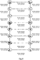
- Fig. 9 shows two conventional antenna arrangements, a standard array 905 and a MIMO array 907, and illustrates the MIMO principle.
- the standard array 905 includes a plurality of antenna elements arranged in a square.
- the antenna elements may, for example, be arranged as an array of 9 ⁇ 9 antenna elements and each comprise a transceiver Tx / Rx (combination of transmitter and receiver).
- the antenna array 907 is a two-dimensional MIMO array having antenna elements arranged in rows at side edges of a square, with transmitters Tx and receivers Rx arranged at different side edges.
- a first transmitter group 910 is arranged on one side edge of the square and a second transmitter group 920 opposite thereto.
- a first receiver group 930 and a second receiver group 940 are disposed on opposite sides of the square, such that the receiver groups 930, 940 together with the transmitter groups 910, 920 form the square.
- a free space 950 is formed, in which no antenna elements are located.
- the antenna arrangement thus formed may, for example, be operated in accordance with the MIMO principle such that the antenna elements of the transmitter groups 910, 920 are successively excited (not simultaneously) according to the time-division multiplexing and the transmitted signals are received by all receivers of the first and second receiver groups 930, 940 , At a given time, only one transmitter ever transmits, so that an evaluation unit can clearly assign the received signals to a transmitter.
- virtual antenna array 390 is an equivalent representation of the MIMO antenna array 907 in the sense that the virtual antenna array is a plurality of receiving antennas that receive a signal from only one transmitting antenna and provide the same result as the MIMO antenna array 907.
- the virtual antenna array 390 comprises four quadrants having a first quadrant array 391, a second quadrant array 392, a third quadrant array 393 and a fourth quadrant array 394.
- the first quadrant array 391 is generated, for example, such that first a first transmitter of the first transmitter group 910 emits a signal, which is received by all receivers of the second receiver group 930. This corresponds to a series of virtual antenna elements in the first quadrant array 391. Thereafter, a second transmitter of the first transmitter group 910 will transmit a signal, which in turn is received by all receive antennas of the first receiver group 930 and thus corresponds to a second row in the first quadrant array 391. This scheme continues until the first quadrant array 391 of the virtual antennas is created.
- the other quadrant arrays 392, 393, 394 are generated.
- the third quadrant array 393 corresponds to the receive antennas of the second receiver group 940 that receive signals from the first transmitter group 910.
- the second quadrant array 392 corresponds to the receive antennas of the first receiver group 930 which receive signals from the second transmitter group 920.
- a comparison of the virtual array 390 with the conventional standard array 905 shows that the MIMO principle allows for aperture doubling in two dimensions, although the MIMO array 907 has the same outer dimensions as the standard array 905. This results in an improved Transverse resolution with a compact design. Furthermore, the MI-MO array 907 is sparse, thus opening up new space in the center of the array (in the space 950), e.g. can be used for other sensors or communication units.
- the prior art designs 905, 907 generally included an ambiguous angle representation, i. There are so-called grating praise in the area of the front half space between +/- 90 ° in azimuth and elevation. In practice, this can produce false targets in the relevant field of view (FoV) of the radar.
- the design 907 includes gaps in the virtual antenna array that must be eliminated by spatial interpolation techniques.
- the design 907 leads to a coupling between transmitting and receiving antennas. This can lead to unwanted disturbances, especially in the case of frequency-modulated continuous waveforms.
- the present invention relates to a MIMO antenna arrangement suitable for three-dimensional radar imaging.
- the MIMO antenna arrangement comprises a first transmit antenna group, a second transmit antenna group and a receive antenna group.
- the first transmission antenna group comprises at least N transmission antennas which are lined up along a first line uniformly with a maximum transmitter spacing.
- the second transmission antenna group comprises at least N transmission antennas which are lined up along a second line uniformly with the maximum transmitter spacing.
- the receive antenna group comprises M receive antennas lined up along at least a third line uniformly with a maximum receiver spacing. There is a minimum distance between the receive antennas and the transmit antennas of the first transmit antenna group formed the first line. The minimum distance along the second line is likewise formed between the receiving antennas and the transmitting antennas of the second transmitting antenna group.
- a MIMO antenna arrangement is an antenna arrangement which operates according to the previously described MIMO principle, wherein the antenna arrangements referred to below are intended to be MIMO antenna arrangements, although not always mentioned.
- the MIMO principle is not limited to the time division multiplex method, but can use general orthogonal signals. Any of a variety of multiplexing methods may be used, in particular using general orthogonal signals (e.g., frequency division multiplexing techniques, orthogonal modulation techniques such as OFDM, CDMA, or other methods).
- the transmit antennas are configured to transmit transmit signals (at a corresponding excitation), and the receive antennas are configured to receive the transmit signals (or their reflections on objects) from all transmit antennas and to forward them to an evaluation unit.
- the total number of transmit antennas is denoted by T and the total number of receive antennas is denoted by R.
- the minimum distance means that no transmitting antenna is closer to one of the receiving antennas as measured along the first or second line. For example, the minimum distance can be at least half of the maximum transmitter distance, but it can also be selected larger. The larger this minimum distance is selected, the more the transmit antennas can be decoupled from the receive antennas. If the minimum distance between both transmission antenna groups is chosen to be the same, there will be no dislocations in the virtual array as described in the Fig. 9 you can see.
- the uniformity of the virtual array also allows the application of Standard method for digital beam forming.
- a high decoupling between transmitting and receiving antennas is achieved, whereby a low-noise operation is possible.
- the maximum transmitter distance and the maximum receiver distance define only upper limits. Therefore, it is not absolutely necessary for all transceivers to have the same distance.
- the positions of the individual transmit antennas and receive antennas (or their distance indications) should not be interpreted so strictly that the relationships must be kept mathematically accurate. Rather, a tolerance range of ⁇ 10% or ⁇ 20% or ⁇ 50% of the defined positions / distances from the definitions should be included.
- the distance between two lines or groups is generally not clearly defined.
- the distance between an antenna group and a further antenna group is defined, for example, by the fact that the individual antenna elements of the respective antenna group have these distances.
- the distance between the first transmission antenna group and the second transmission antenna group is measured by consecutively numbering the individual transmission antennas in the transmission groups (in a certain direction) the distance between the first transmission antenna from the one group and the first transmission antenna from the second group is measured. The same can be done analogously for the other transmitting antennas. It is also possible to define the spacing of the antenna groups as the maximum or minimum distance between individual antennas.
- the transmit antennas are configured to transmit transmit signals having a wavelength ⁇
- the maximum transmitter spacing and / or the maximum receiver spacing have a maximum value of ⁇ / 2 or a value in a range between ⁇ / 2 to ⁇ .
- the value can for example, be determined to a fault tolerance of ⁇ 30%.
- the first line and the second line are substantially parallel to the y-axis and the third line is substantially parallel to x Axis, so that all transmit antennas have respective y-values that are greater by the minimum distance than the common y-value of the receiving antennas.
- the antenna arrangement comprises a further receiving antenna group with at least M further receiving antennas, which are strung along a fourth line.
- the further (or second) receive antenna group may be parallel to the first receive antenna group in a receive antenna group spacing of at most N * d1 (when d1 is the maximum transmitter spacing).
- the first transmit antenna group is parallel to the second transmit antenna group in a transmit antenna array spacing of at most M * d2 (when d2 is the maximum receiver spacing).
- a distance from the first line to an mth receiving antenna may be, for example, maximum (k m +1/2) * d2, where k m is an integer specific to the mth receiving antenna.
- the integer k m can be chosen arbitrarily.
- An advantage of this embodiment is that decoupling between the transmitter antennas and receiving antennas can be improved. In particular, if the integer k m is chosen to be large enough, the transmitter antennas completely decouple from the receiving antennas. In addition, a high uniformity of the virtual array is achieved at the same time.
- a distance from the third line to an nth transmit antenna is at most (l n +1/2) * d1, where l n is a specific for the nth transmit antenna integer is.
- the integer l n can be chosen arbitrarily. This relationship applies to all broadcast antennas, whether they belong to the first or second broadcast antenna group. If only one receive antenna group (one line) is used, the discrete raster (l n +1/2) * d1 need not be used, so that this distance may be, for example, c * d1 (c arbitrary).
- An advantage of this embodiment is that the decoupling between the receiver antennas and the transmitter antennas is improved, while at the same time achieving a high degree of uniformity of the virtual array.
- the degree of decoupling can, for example, by a choice of the integer l n can be achieved, the larger this integer is chosen, the higher the decoupling of the receiving antennas from the transmitter antennas.
- the antenna arrangement comprises at least one additional receiving antenna which is arranged along the third line and / or along the fourth line laterally next to one of the receiving antennas with the transmitter spacing. They are thus arranged offset in the y-direction to the receiving antennas.
- the first transmission antenna group may be parallel to the second transmission antenna group in a transmission antenna group pitch of at most (M-1) * d2.
- the antenna arrangement comprises one or more passive antenna elements which are arranged with the maximum transmitter spacing or the maximum receiver spacing laterally next to one of the transmit antennas or laterally next to one of the receive antennas.
- the total number of passive antenna elements is denoted by P.
- one or more transmitting antennas or one or more receiving antennas may be arranged between two passive antenna elements.
- Passive antenna elements may be, for example, transmitting antennas or also receiving antennas, which do not necessarily differ structurally from the other antennas. However, they are not activated so that they do not transmit any transmission signals or actively receive and transmit transmission signals.
- An advantage of this approach is that it makes it possible to optimize the antenna pattern (eg the radiation pattern) in both azimuth and elevation.
- the passive antennas cause that all antenna elements as defined above behave the same way as internal or internal antenna elements and not like edge antenna elements.
- each transmit antenna is disposed along the first line and along the second line between two passive antenna elements.
- Each antenna element may be disposed (along the third line and / or along the first and second lines) between two passive antenna elements. All transmit antennas of a group can be arranged, for example, between two passive antenna elements. Passive antenna elements are arranged, for example, on the outer edge of the groups, so that no passive antenna elements are arranged between two transmitting antennas.
- the transmit antennas of the first transmit antenna group and / or the second transmit antenna group are formed as patch antennas having a respective phase center, the phase centers of the respective patch antennas being at the positions of the original transmit antennas.
- a shield member is formed between the first transmission antenna group and the reception antenna group and / or between the second transmission antenna group and the reception antenna group to prevent or suppress direct reception of the signals emitted by the transmission antennas by the reception antennas. As a result, an additional decoupling can be achieved.
- the antenna arrangement comprises a control unit, wherein the control unit is designed to control the transmission antennas to control via a multiplexing method and the receiving antennas are adapted to receive transmission signals from all transmitting antennas or reflections on objects.
- control unit may be configured to use a time division multiplex method for transmitting the transmission signals and to determine a relative movement of the object to the antenna arrangement based on reception signals from the at least one additional reception antenna and / or a further reception antenna along the row of reception antennas Motion compensation is enabled.
- the at least one additional receiving antenna and / or the further receiving antenna represent (spatially) overlapping positions in the virtual array, so that at different times of the time division multiplexing the overlapping positions are detected multiple times (temporal bridge) and thus a motion detection is possible.
- the present invention relates to a method for three-dimensional radar imaging of an object or the environment using a previously described antenna arrangement.
- the method comprises the steps of: transmitting orthogonal transmit signals through the transmit antennas, receiving reflection signals of the orthogonal transmit signals reflected from the object or the environment, and evaluating the received reflectance signals to produce a three-dimensional image of the object or the environment.
- orthogonal signals are to be understood as meaning all signals which can be transmitted in parallel or simultaneously in a predetermined period of time without the signals influencing or interfering with each other.
- the orthogonality of the signals may relate to the time domain (eg by a time division multiplex method), to the frequency domain (eg by a frequency division multiplexing method), to the coding (eg by orthogonal codes), or to another multiplexing method.
- This method may also be implemented or stored in the form of instructions in software or on a computer program product, wherein the stored instructions are capable of performing the steps of the method when the method is executed on a processor (eg in a controller of a receiving module or a computer) Radar system) is running. Therefore, the present invention also relates to a computer program product having software code (software instructions) stored thereon configured to perform one of the above-described methods or to provide functions when the software code is executed by a processing unit.
- the processing unit may be any form of computer or control unit having a corresponding microprocessor capable of executing a software code.
- the method may also be implemented by an application specific hardware, in particular a field programmable gate array (FPGA) unit (FPGA) when the application specific hardware couples to the MIMO antenna array to control it.
- FPGA field programmable gate array
- the present invention also relates to an antenna assembly suitable for three-dimensional radar imaging.
- the antenna arrangement comprises a first transmit antenna group, a second transmit antenna group, and a receive antenna group.
- the first transmission antenna group comprises at least N transmission antennas which are lined up along a first line uniformly with a maximum transmitter spacing.
- the second transmission antenna group comprises at least N transmission antennas which are lined up along a second line uniformly with the maximum transmitter spacing.
- the receive antenna group comprises M receive antennas lined up along at least a third line uniformly with a maximum receiver spacing.
- the transmission antennas are configured to transmit transmission signals having a wavelength ⁇ , and the maximum transmitter distance and / or the maximum receiver distance have a maximum value of ⁇ / 2 or a value in a range between ⁇ / 2 and ⁇ . For example, the value can be up to one Fault tolerance of ⁇ 30% must be determined.
- Fig. 1A shows an antenna arrangement according to an embodiment of the present invention, which can use the MIMO principle.
- a minimum distance d3 is formed between the transmitting antennas of the first transmitting antenna group 110 and the receiving antennas of the receiving antenna group 130, and the minimum distance d3 is also formed between the transmitting antennas of the second transmitting antenna group 120 and the receiving antennas of the receiving antenna group 130.
- the Minimum distance d3 is at least as large as d1 or d2 (eg measured along the first or second line 210, 220).
- the minimum distance d3 to the first transmitting antenna group 110 may be equal to the minimum distance d3 to the second transmitting antenna group 120 (measured respectively from the receiving antenna group 130 along the first line 210 or along the second line 220).
- Fig. 1B shows the associated virtual antenna array 300 with virtual antennas when the antenna arrangement according to the MIMO principle is operated (ie, it is a MIMO antenna array).
- the virtual antenna array 300 has N rows of virtual antennas, with 2 * M virtual antennas strung in each row.
- the number of antenna elements may be arbitrarily selected in both the first transmission antenna group 110 and the second transmission antenna group 120 or in the reception antenna group 130. However, a uniform array of virtual antennas is achieved only if the number of transmit antennas in the first transmit antenna group 110 is equal to the number of transmit antennas in the second transmit antenna group 120. As in the embodiment shown, the first line 210 and the second line are also 220 are arranged parallel to each other, so that the virtual array 300 represents a uniform rectangular arrangement. Again, this is not mandatory, but can be varied accordingly.
- the arrangement shown is capable of satisfying the above criteria (a) and (b), for example, when the maximum transmitter distance d1 and / or the maximum receiver distance d2 is at most ⁇ / 2, where ⁇ is the wavelength of the radar radiation used.
- the angular ambiguities ie the first grating praise, occur in the Boresight mode (azimuth / elevation angle 0 °) at +/- 180 °.
- the angular ambiguity occurs at the corresponding - / + 90 °, so is for the FoV of the radar (front half-space) uncritical. Accordingly, it is advantageous to select an element spacing of ⁇ / 2 in azimuth and elevation over the entire front half-space for a two-dimensional antenna array with electronic beam sweep.
- the relative distances of the individual transmitting and receiving antenna groups are appropriately selected.
- this is not fulfilled, because in the center of the virtual aperture arises z. B. a gap.
- the embodiment of the Fig. 1 does not suffer from this disadvantage and achieves a MIMO physical array design with gapless, uniform virtual aperture in two dimensions.
- the receive antenna group 130 is exemplified along the x-axis, and the transmit antenna groups 110, 120 are arranged perpendicular to the receive antenna group 130 along the y-axis.
- the alignment of the transmission antenna groups 110, 120 along the y-axis is arbitrary.
- a virtual antenna array 300 with 2 * M * N elements results.
- a suitable value for the antenna distance d 2 within the receive group 130 may also be used d 2 ⁇ ⁇ / 2 . ⁇ to get voted.
- the distance between the two transmission antenna groups 110, 120 can then be M * d2, and the alignment of the transmission antenna groups 110, 120 along the x-axis can be such that in the x-direction to each reception antenna m (1 ⁇ mm ⁇ M) gives a distance dm of (k m + 1/2) * d2.
- a suitable value for the element spacing d1 within the transmission antenna groups 110, 120 may also be used d 1 ⁇ ⁇ / 2 . ⁇ to get voted. There are no further changes to the array design.
- Fig. 2A shows a further embodiment of an antenna arrangement.
- the receive antenna group 130 now comprises two receive antenna groups: a first receive antenna group 130a and a second receive antenna group 130b.
- the first receiving antenna group 130a may be the same as the receiving antenna group 130 of FIG Fig. 1
- the distance between the transmit antenna groups 110, 120 to the first receive antenna group 130a is set to maintain a minimum distance of d3 (where d3 ⁇ d1 or d3 ⁇ d2 can be selected). A repeated description is therefore not required.
- the further formed second receiving antenna group 130b is spaced from the first receiving antenna group 130a by a distance d4. For the distance d4, for example: d 4 ⁇ N * d 1.
- the shape of the virtual array 300 can be chosen more flexibly. For example, when the number M of the receiving antennas in the first receiving antenna group 130a is equal to the number of receiving antennas in the second receiving antenna group 130b, the illustrated rectangular array 300 of virtual antennas results.
- relatively few transmitting antennas can be used to create shapes for the virtual antenna array 300, which are wider in the y-direction than the antenna arrangement of FIG Fig. 1 , For example, in the particular embodiment shown, virtual aperture doubling in two dimensions is achieved.
- the receiving antenna groups 130a, 130b may be formed parallel to each other along the x-axis.
- the transmit antenna groups 110, 120 are aligned perpendicular to the receive antenna groups 130a, 130b and parallel to each other along the y-axis.
- the distance d0 between the two transmission antenna groups 110, 120 is again maximally M ⁇ d (or d0 ⁇ M * d)
- the distance d4 between the two reception antenna groups 130a, 130b is again maximally N * d (or d4 ⁇ N * d)
- the orientation of the receiving antenna groups 130a, 130b along the y-axis is, for example, such that in the y-direction to each transmitting element n a distance dn of at most (l n + 1/2) * d results, where l n is an integer , which depends on the index n of the considered transmission element.
- the alignment of the transmission antenna groups 110, 120 along the x-axis can again take place in such a way that x direction to each receiving element m is a distance dm of at most (k m + 1/2) ⁇ d, where k m is an integer that depends on the index m of the receiving element under consideration.
- the distance d0 between the two transmission antenna groups 110, 120 can then be M * d2, and the alignment of the transmission antenna groups 110, 120 along the x-axis can be such that in the x-direction to each reception element m a distance dm of max. k m + 1/2) * d2 yields (as d0 in Fig. 1A ). If the electronic beam tilting only covers a limited angular range of +/- ⁇ max in the elevation direction, a suitable value for the element spacing within the transmission antenna groups may also be used d 1 ⁇ ⁇ / 2 . ⁇ to get voted.
- the distance d4 between the two receiving antenna groups 130a, 130b can then be maximally N * d1, and the orientation of the receiving antenna groups 130a, 130b along the y-axis can be such that in the y-direction to each transmitting element n a distance dn of at most (l n + 1/2 ) * d1 results.
- the transmit antenna groups 110, 120 can be arbitrarily shifted along the y-axis without causing changes to the resulting virtual array (apart from a phase shift affecting all virtual elements equally and translating the corresponds to virtual arrays in space).
- These degrees of freedom can also be found in Fig. 2A be used to spatially separate the transmit antenna groups 110, 120 and the receive antenna groups 130a, 130b in order to achieve a correspondingly high decoupling between the transmit and receive elements. In the embodiments of the Fig. 1 and Fig. 2 this has already been exploited by shifting the transmit antenna groups 110, 120 along the y-axis. The resulting from the spatial separation of the transmitting and receiving antennas decoupling can be determined by measurement and adapted to the desired requirements accordingly.
- the receiving antennas are in turn arranged in a row from a first receiving antenna 130a to a last receiving antenna 139.
- the transmitter group spacing d0 between the first transmission antenna group 110 and the second transmission antenna group 120 is reduced by a value d2 (maximum receiver distance) so that now: d 0 ⁇ M - 1 * d Second
- both transmit antenna groups 110, 120 are shifted "inward" along the x-axis by d2 / 2, so that all transmit antennas of the first transmit antenna group 110 are perpendicular above the first receive antenna 131 and all transmit antennas of the second transmission antenna group 120 are arranged above the last reception antenna 139.
- this does not necessarily have to be the case. Rather, the transmit antenna groups 110, 120 and receive antenna group 130 relative to each other by integer multiples of the transmitter or. Receiver distances are moved (see description to Fig. 1 ).
- the additional receiving antenna 410 is arranged by way of example next to the eighth receiving antenna 138, namely at a maximum transmitter distance d1.
- the additional receiving antenna 410 is arranged laterally on the side to the transmitting antennas of the first transmitting antenna group 110 and the second transmitting antenna group 120, respectively.
- the additional receiving antenna 410 can also be arranged on the opposite side of the lined-up receiving antennas.
- the transmit antennas (Tx) have been numbered by way of example as follows: first transmission antenna group 110: second transmission antenna group 120: TX01 TX02 TX03 TX04 TX05 TX06 Tx07 TX08 TX09 Tx10 Tx11 TX12 TX13 TX14 TX15 TX16
- Fig. 3B shows that to the antenna arrangement of Fig. 3A associated virtual array 300.
- the additional receive antenna 410 results in forming in the virtual antenna array 300, using time division multiplexing, "time" bridges 310, 320 that establish connections between every two time slots in a time division multiplex cycle.
- Each transmitted transmission signal (e.g., from the transmission antenna Tx01) is received by the row-shaped reception antennas 131 ... 139 as a plurality of reception signals.
- another receive signal is received by the additional receive antenna 410, but this corresponds to a position 341 in the virtual array 300 laterally shifted toward the transmit antennas Tx01 ... Tx16. Therefore, when transmitting a transmission signal by a next transmission antenna Tx03, the position 341 is detected again, but this time corresponds to the reception antenna 138 in the physical antenna array disposed laterally adjacent to the additional reception antenna 410.
- the position 341 in the virtual array 300 is thus detected twice. Since the double detection takes place at different times, the named "temporal" bridges result.
- Another overlap in the virtual array 300 concerns the virtual antennas 330.
- This overlap comes from the shift of the transmit antenna groups 110, 120, to a value of each d2 / 2 inward.
- This shift causes all virtual antennas 330 to be detected twice (eg, in consecutive time slots).
- the reception of the transmission signal from the first transmission antenna Tx01 by the last reception antenna 139 corresponds to the virtual antenna 339.
- this virtual antenna 339 also corresponds to receiving another transmission signal from the second transmission antenna Tx02 through the first reception antenna 131.
- the time bridges 310 , 320 vertical connections, while the overlaps 330 form horizontal connections, so that all the time slots are interconnected.
- the virtual array 300 includes additional redundant receive antennas 340, which also arise through the additional receive antenna 410 and can be eliminated in the evaluation.
- Fig. 3 therefore allows a physical MIMO array design with gapless, uniform virtual aperture in two dimensions and the principal possibility for Doppler evaluation (consideration of relative movements between the antenna array and a detected object) in the case of time-division multiplexing.
- Fig. 4 illustrates the "temporal" bridges through a graph.
- the existing branches represent the existing temporal "bridges" due to the multiply-generated virtual elements.
- Tx01 the transmitting antenna
- Tx03 the receiving antennas 138 and 139
- the detection or consideration of a relative movement can be achieved if in the overall graph of each node K n (transmitting element Tx n ) at least one path to each other node K n ' (transmitting element Tx n' , n ' ⁇ n ) can be reached.
- the vertical edges are generated in the example by the additional receiving element 410 and the horizontal edges by moving the transmitting antenna groups.
- the Graphene framework can be systematically applied to two-dimensional, gapless, uniform virtual aperture physical MIMO array designs.
- Fig. 5 shows a further embodiment for the formation of additional additional receiving antennas.
- a further additional receiving antenna 420 laterally offset from one of the receiving antennas of the second group 130b formed by receiving antennas.
- the effect is the same as in the Fig. 3 , That is, even in this embodiment, there is an overlap of virtual antennas, since in one two virtual antenna positions are active for a given period of time, the bridges thus obtained extending both in the vertical direction (through the additional receiving antennas 410, 420) and extending in the horizontal direction, by the offset of the transmitting antenna groups 110, 120.
- Fig. 6 shows a further embodiment, which is a development of the antenna arrangement of the Fig. 5A representing passive antenna elements (crossed circles).
- passive antenna elements can be transmitter as well as receive antennas, which actively neither send nor receive signals.
- the active antennas eg as shown in FIGS Fig. 1 to 5 are shown
- the antennas at the ends of the arrayed antenna groups thus behave like inner antenna elements and not like edge antennas. In order to achieve this effect, however, it is not necessary to form a passive antenna element between two adjacent active antennas.
- a first passive element 511 and a second passive element 512 are formed, between which the first transmission antenna group 110 is located.
- a third passive antenna element 513 and a fourth passive antenna element 514 are formed along the second row 220 such that the transmitting antennas of the second transmitting antenna group 120 are interposed between the third passive antenna element 513 and the fourth passive antenna elements 514 are located.
- the first receiving antenna group 130a includes a first receiving antenna 131a, a second receiving antenna 132a, etc., a seventh receiving antenna 137a, and the additional receiving antenna 410.
- the second receiving antenna group 130b includes a first receiving antenna 131b, a second receiving antenna 132b, etc , a seventh receiving antenna 137b, and the other additional receiving antenna 420.
- each receiving antenna 131a, b ... 137a, b is disposed between every two passive antenna elements.
- the first reception antenna 131 a of the first reception antenna group 130 a is formed between a fifth passive antenna element 531 a and a sixth passive reception antenna element 532 a, and the fourth reception antenna 134 a and the further auxiliary antenna 410 are combined between a seventh passive antenna element 534 a and an eighth passive reception antenna element 535 a arranged.
- further passive antenna elements 541, 542, 543, 544 may also be formed along the x direction, such that the first reception antenna group 130a is arranged along the x axis between at least two further passive antenna elements 541, 542.
- the second receive antenna group 130b may be laterally delimited along the x-axis by further passive antenna elements 543, 544.
- the present invention should not be limited to the illustrated arrangement of passive antennas. Rather, only a part of the passive antennas need to be formed. For example, only a portion of the antenna arrays 110, 120, 130a, 130b need be located between or adjacent to passive antennas. In addition, the antenna groups 110, 120, 130a, 130b to be limited only by one side by passive antenna elements. Which of the passive antennas where best is to be arranged, can be adapted to the specific circumstances or be determined by measurement.
- a MIMO array with gap-free, uniform virtual aperture in two dimensions can be achieved, which allows Doppler evaluation in the case of time-division multiplexing and in which passive antenna elements are used to optimize the antenna pattern.
- the passive elements can be positioned on the grid k m * d (in x-direction) or I n * d (in y-direction). The resulting effects on the antenna diagram can be determined metrologically and taken into account accordingly.
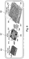
- Fig. 7A shows a further embodiment, which starting from the embodiment of the Fig. 5 a further optional embodiment of the transmitting antennas comprises in order to achieve a transmitting side pre-focusing.
- the transmit antennas are replaced by patch antennas, which in turn are grouped into transmit antenna groups 110p, 120p.
- the first transmission antenna group 110p comprises 6 patch antennas, the phase center of which is located at those positions at which previously (see FIG Fig. 5 ) have found the individual transmit antennas.
- the second transmission antenna group 120p which has also been replaced by 6 patch antennas in the exemplary embodiment shown.
- the patch antennas were arranged so that the phase center of the individual patch antennas located at the positions, as it is with the Fig. 5 has been described.
- Fig. 7B shows an example of a multipatch antenna with a sheet-like geometry, wherein a pre-focusing in the vertical longitudinal extent of the patch antenna shown is achieved.
- Each point in the patcharrays 110p, 120p from the Fig. 7A corresponds to the in Fig. 7B shown patch antenna, which extends for example in the y direction.
- the arrangement of the transmitting antenna groups 110p, 120p and the receiving antenna groups 130a, 130b became as compared with the antenna arrangement Fig. 5A turned by 90 degrees.
- This offers the following advantage.
- the patch array physically occupies a larger area in the direction in which it is to be pre-focused (eg, quadruple; Fig. 7B ). In Fig. 7A this would be the y direction.
- the pre-focusing is typically used only on the transmitting side, since then you can achieve a corresponding antenna gain and thus a signal-to-noise ratio (SNR) improvement.
- SNR signal-to-noise ratio
- prefocusing in the y direction is desirable.
- this would be for the antenna arrangement of the Fig. 5A cause the individual transmit antennas to be further apart.
- the advantageous ⁇ / 2 distance in the resulting virtual array would be difficult to meet.
- the transmitting antennas in the Fig. 7A are arranged in the x-direction, this can be implemented easily in practice.
- the antenna arrangement allows the Fig. 7A a physical MIMO array with continuous, uniform virtual aperture in two dimensions, which allows Doppler evaluation in the case of time-division multiplexing.
- a transmit-side prefocusing of the antenna pattern is achieved.
- the phase centers of the multipatch elements on the raster k m * n * d can be (in the x direction) and I d (in y-direction).
- the resulting effects on the antenna pattern can be determined metrologically and taken into account in the alignment.
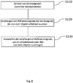
- FIG. 10 shows a flowchart for a method for three-dimensional radar imaging for an object using an antenna arrangement according to one of the preceding claims.
- the method comprises the following steps: sending S110 of (orthogonal) transmit signals through the transmit antennas; Receiving S120 of reflection signals of the (orthogonal) transmission signals reflected from the object; and evaluating S130 the received reflection signals to produce a three-dimensional image of the object.
- the method can also be implemented on a control device (for example a radar system) in the form of software that makes it possible to control the radar system.
- a control device for example a radar system
- Further exemplary embodiments therefore also include a storage medium with a computer program stored thereon, which is designed to cause a device to carry out the previously described method when it runs on a processor (processing unit).
- the storage medium may be a machine-readable medium that includes a mechanism for storing or transferring data in a form readable by a machine (e.g., a computer).
- the device may, for example, be a control module with a processor running the computer program.
- embodiments allow an aperture extension in two dimensions, improve the achievable antenna pattern through the use of passive antenna elements and allow pre-focusing.
Landscapes
- Engineering & Computer Science (AREA)
- Remote Sensing (AREA)
- Radar, Positioning & Navigation (AREA)
- Physics & Mathematics (AREA)
- Computer Networks & Wireless Communication (AREA)
- General Physics & Mathematics (AREA)
- Electromagnetism (AREA)
- Variable-Direction Aerials And Aerial Arrays (AREA)
- Radar Systems Or Details Thereof (AREA)
Priority Applications (1)
| Application Number | Priority Date | Filing Date | Title |
|---|---|---|---|
| EP16001077.3A EP3244231A1 (fr) | 2016-05-12 | 2016-05-12 | Systeme d'antenne mimo et procede d'imagerie radar tridimensionnelle |
Applications Claiming Priority (1)
| Application Number | Priority Date | Filing Date | Title |
|---|---|---|---|
| EP16001077.3A EP3244231A1 (fr) | 2016-05-12 | 2016-05-12 | Systeme d'antenne mimo et procede d'imagerie radar tridimensionnelle |
Publications (1)
| Publication Number | Publication Date |
|---|---|
| EP3244231A1 true EP3244231A1 (fr) | 2017-11-15 |
Family
ID=55968865
Family Applications (1)
| Application Number | Title | Priority Date | Filing Date |
|---|---|---|---|
| EP16001077.3A Pending EP3244231A1 (fr) | 2016-05-12 | 2016-05-12 | Systeme d'antenne mimo et procede d'imagerie radar tridimensionnelle |
Country Status (1)
| Country | Link |
|---|---|
| EP (1) | EP3244231A1 (fr) |
Cited By (8)
| Publication number | Priority date | Publication date | Assignee | Title |
|---|---|---|---|---|
| CN108256696A (zh) * | 2018-03-16 | 2018-07-06 | 电子科技大学 | 一种结合状态预测和粒子群优化的组网雷达天线配置方法 |
| CN108776337A (zh) * | 2018-04-24 | 2018-11-09 | 桂林电子科技大学 | Mimo-fda探地雷达近目标二维成像方法 |
| CN111007504A (zh) * | 2019-12-20 | 2020-04-14 | 北京理工大学 | 基于最小冗余的mimo三维成像雷达稀疏阵列设计方法 |
| CN112859072A (zh) * | 2021-01-20 | 2021-05-28 | 北京环境特性研究所 | 一种基于平面mimo阵列的雷达系统及三维成像方法 |
| US20210184367A1 (en) * | 2017-10-10 | 2021-06-17 | Panasonic Intellectual Property Management Co., Ltd. | Radar apparatus |
| US11360210B2 (en) * | 2019-07-02 | 2022-06-14 | Intel Corporation | Multi-mode multi-input multi-output (MIMO) radar sensors |
| US11573310B2 (en) * | 2017-01-31 | 2023-02-07 | Arbe Robotics Ltd. | Compact radar switch/MIMO array antenna with high azimuth and elevation angular resolution |
| US11811142B2 (en) | 2018-09-05 | 2023-11-07 | Arbe Robotics Ltd. | Skewed MIMO antenna array for use in automotive imaging radar |
Citations (8)
| Publication number | Priority date | Publication date | Assignee | Title |
|---|---|---|---|---|
| US20100220001A1 (en) * | 2007-09-19 | 2010-09-02 | Teledyne Australia Pty Ltd | Imaging system and method |
| CN102866401A (zh) * | 2012-08-06 | 2013-01-09 | 西北工业大学 | 一种基于mimo技术的三维成像方法 |
| DE102011083756A1 (de) * | 2011-09-29 | 2013-04-04 | Siemens Ag | Radar-Vorrichtung und Verfahren zum Erzeugen einer Gruppencharakteristik eines Radars |
| US8570210B1 (en) | 2011-06-21 | 2013-10-29 | Lockheed Martin Corporation | Aircraft MIMO radar |
| GB2510969A (en) * | 2012-12-19 | 2014-08-20 | Rohde & Schwarz | A device for the measurement of microwave signals and a method for the configuration of the same |
| DE102013105809A1 (de) * | 2013-06-05 | 2014-12-11 | Airbus Defence and Space GmbH | Multifunktionale Radaranordnung |
| EP2857858A1 (fr) * | 2013-10-03 | 2015-04-08 | Honeywell International Inc. | Radar actif numérique |
| DE102013220131A1 (de) * | 2013-10-04 | 2015-04-09 | Rohde & Schwarz Gmbh & Co. Kg | Bildgebungssystem mit orthogonalen Sendesignalen |
-
2016
- 2016-05-12 EP EP16001077.3A patent/EP3244231A1/fr active Pending
Patent Citations (8)
| Publication number | Priority date | Publication date | Assignee | Title |
|---|---|---|---|---|
| US20100220001A1 (en) * | 2007-09-19 | 2010-09-02 | Teledyne Australia Pty Ltd | Imaging system and method |
| US8570210B1 (en) | 2011-06-21 | 2013-10-29 | Lockheed Martin Corporation | Aircraft MIMO radar |
| DE102011083756A1 (de) * | 2011-09-29 | 2013-04-04 | Siemens Ag | Radar-Vorrichtung und Verfahren zum Erzeugen einer Gruppencharakteristik eines Radars |
| CN102866401A (zh) * | 2012-08-06 | 2013-01-09 | 西北工业大学 | 一种基于mimo技术的三维成像方法 |
| GB2510969A (en) * | 2012-12-19 | 2014-08-20 | Rohde & Schwarz | A device for the measurement of microwave signals and a method for the configuration of the same |
| DE102013105809A1 (de) * | 2013-06-05 | 2014-12-11 | Airbus Defence and Space GmbH | Multifunktionale Radaranordnung |
| EP2857858A1 (fr) * | 2013-10-03 | 2015-04-08 | Honeywell International Inc. | Radar actif numérique |
| DE102013220131A1 (de) * | 2013-10-04 | 2015-04-09 | Rohde & Schwarz Gmbh & Co. Kg | Bildgebungssystem mit orthogonalen Sendesignalen |
Non-Patent Citations (6)
| Title |
|---|
| BROOKNER ELI: "MIMO radar demystified and where it makes sense to use", 2013 IEEE INTERNATIONAL SYMPOSIUM ON PHASED ARRAY SYSTEMS AND TECHNOLOGY, IEEE, 15 October 2013 (2013-10-15), pages 399 - 407, XP032562863, DOI: 10.1109/ARRAY.2013.6731862 * |
| PRECHTEL, U.; MEENAKSHISUNDARAM, V.; SCHOENLINNER, B.; ZIEGLER, V.; FELDLE, H.-P.; MEUSLING, A.: "Short-Range MIMO Radar System Considerations", ANTENNAS AND PROPAGATION (EUCAP), 2012 6TH EUROPEAN CONFERENCE ON, pages 1742 - 1745 |
| SCHMID C M ET AL: "Motion compensation and efficient array design for TDMA FMCW MIMO radar systems", 2012 6TH EUROPEAN CONFERENCE ON ANTENNAS AND PROPAGATION (EUCAP), 26 March 2012 (2012-03-26) - 30 March 2012 (2012-03-30), IEEE Piscataway, NJ, USA, pages 1746 - 1750, XP002762927, ISSN: 2164-3342, ISBN: 978-1-4577-0918-0, DOI: 10.1109/EUCAP.2012.6206605 * |
| SCHMID, C.M.; FEGER, R.; PFEFFER, C.; STELZER, A.: "Motion Compensation and Efficient Array Design for TDMA FMCW MIMO Radar Systems", ANTENNAS AND PROPAGATION (EUCAP), pages 1746 - 1750 |
| SPRENG, T.; PRECHTEL, U.; SCHONLINNER, B.; ZIEGLER, V.; MEUSLING, A.; SIART, U.: "UWB Near-Field MIMO Radar: Calibration, Measurements and Image Reconstruction", RADAR CONFERENCE (EURAD), 2013 EUROPEAN, pages 33 - 36 |
| YUAN SHUAI ET AL: "110-140-GHz single-chip reconfigurable radar frontend with on-chip antenna", 2015 IEEE BIPOLAR/BICMOS CIRCUITS AND TECHNOLOGY MEETING - BCTM, IEEE, 26 October 2015 (2015-10-26), pages 48 - 51, XP032821604, DOI: 10.1109/BCTM.2015.7340553 * |
Cited By (9)
| Publication number | Priority date | Publication date | Assignee | Title |
|---|---|---|---|---|
| US11573310B2 (en) * | 2017-01-31 | 2023-02-07 | Arbe Robotics Ltd. | Compact radar switch/MIMO array antenna with high azimuth and elevation angular resolution |
| US20210184367A1 (en) * | 2017-10-10 | 2021-06-17 | Panasonic Intellectual Property Management Co., Ltd. | Radar apparatus |
| US11670866B2 (en) * | 2017-10-10 | 2023-06-06 | Panasonic Intellectual Property Management Co., Ltd. | Radar apparatus using transmitting array antenna and receiving array antenna |
| CN108256696A (zh) * | 2018-03-16 | 2018-07-06 | 电子科技大学 | 一种结合状态预测和粒子群优化的组网雷达天线配置方法 |
| CN108776337A (zh) * | 2018-04-24 | 2018-11-09 | 桂林电子科技大学 | Mimo-fda探地雷达近目标二维成像方法 |
| US11811142B2 (en) | 2018-09-05 | 2023-11-07 | Arbe Robotics Ltd. | Skewed MIMO antenna array for use in automotive imaging radar |
| US11360210B2 (en) * | 2019-07-02 | 2022-06-14 | Intel Corporation | Multi-mode multi-input multi-output (MIMO) radar sensors |
| CN111007504A (zh) * | 2019-12-20 | 2020-04-14 | 北京理工大学 | 基于最小冗余的mimo三维成像雷达稀疏阵列设计方法 |
| CN112859072A (zh) * | 2021-01-20 | 2021-05-28 | 北京环境特性研究所 | 一种基于平面mimo阵列的雷达系统及三维成像方法 |
Similar Documents
| Publication | Publication Date | Title |
|---|---|---|
| EP3244231A1 (fr) | Systeme d'antenne mimo et procede d'imagerie radar tridimensionnelle | |
| DE102013105809B4 (de) | Multifunktionale Radaranordnung | |
| EP2191297B1 (fr) | Procédé faisant appel à un radar à synthèse d'ouverture | |
| DE102017210137B4 (de) | Radarvorrichtung und Verfahren zum Verarbeiten eines Radarsignals | |
| DE102005062901B4 (de) | System und Verfahren zum Mikrowellenabbilden unter Verwendung eines verschachtelten Musters in einem programmierbaren Reflektorarray | |
| EP3309523B1 (fr) | Jauge destinée à déterminer une topologie d'une surface de matériau de remplissage | |
| DE102014118031A1 (de) | Radarsensor, Radarsensor-System sowie Verfahren zur Bestimmung der Position eines Objekts mit horizontaler und vertikaler digitaler Strahlformung zur Vermessung von punkt- und flächenförmig reflektierenden Objekten | |
| DE102011083756A1 (de) | Radar-Vorrichtung und Verfahren zum Erzeugen einer Gruppencharakteristik eines Radars | |
| DE112019006800T5 (de) | Antennenvorrichtung und Radarvorrichtung | |
| EP3803454B1 (fr) | Procédé radar à ouverture synthetique et dispositif radar à ouverture synthetique | |
| DE112008000513T5 (de) | Elektronisch abtastendes Radarsystem und Empfangsantenne | |
| DE102017210781A1 (de) | Radarantenne für ein Füllstandmessgerät | |
| DE102018217110A1 (de) | Radarsystem, sowie eine geeignete Verwendung und Verfahren hierfür | |
| DE102018207686A1 (de) | MIMO-Radarsensor für Kraftfahrzeuge | |
| DE102018118863A1 (de) | Radarvorrichtung und Verfahren zum Erzeugen unterschiedlicher Richtcharakteristika | |
| DE102015221163A1 (de) | Verfahren und Vorrichtung zur Verfolgung von Objekten, insbesondere sich bewegenden Objekten, in den dreidimensionalen Raum von abbildenden Radarsensoren | |
| DE102021100695B4 (de) | Verfahren zum Betrieb eines Topologie-erfassenden Radarsystems innerhalb eines Behälters | |
| DE2306407C3 (de) | Antennensystem hoher Winkelauflösung für Radargeräte mit getrennten Sende- und Empfangsantennen | |
| WO2017072048A1 (fr) | Procédé et dispositif de suivi d'objets, en particulier d'objets en mouvement, dans l'espace tridimentionnel de capteurs radars imageurs | |
| EP2722686B1 (fr) | Système sar interférométrique | |
| DE112019005668T5 (de) | Antennenvorrichtung und radarsystem | |
| DE102010041755A1 (de) | Radarsystem | |
| EP3564708B1 (fr) | Procédé radar à synthèse d'ouverture permettant de télédétecter la surface de la terre et dispositif radar à synthèse d'ouverture | |
| WO2020225314A1 (fr) | Système de radar multistatique cohérent, en particulier pour une utilisation dans un véhicule | |
| WO2019158251A1 (fr) | Système d'antenne pour un capteur radar |
Legal Events
| Date | Code | Title | Description |
|---|---|---|---|
| PUAI | Public reference made under article 153(3) epc to a published international application that has entered the european phase |
Free format text: ORIGINAL CODE: 0009012 |
|
| STAA | Information on the status of an ep patent application or granted ep patent |
Free format text: STATUS: THE APPLICATION HAS BEEN PUBLISHED |
|
| AK | Designated contracting states |
Kind code of ref document: A1 Designated state(s): AL AT BE BG CH CY CZ DE DK EE ES FI FR GB GR HR HU IE IS IT LI LT LU LV MC MK MT NL NO PL PT RO RS SE SI SK SM TR |
|
| AX | Request for extension of the european patent |
Extension state: BA ME |
|
| STAA | Information on the status of an ep patent application or granted ep patent |
Free format text: STATUS: REQUEST FOR EXAMINATION WAS MADE |
|
| 17P | Request for examination filed |
Effective date: 20180514 |
|
| RBV | Designated contracting states (corrected) |
Designated state(s): AL AT BE BG CH CY CZ DE DK EE ES FI FR GB GR HR HU IE IS IT LI LT LU LV MC MK MT NL NO PL PT RO RS SE SI SK SM TR |
|
| STAA | Information on the status of an ep patent application or granted ep patent |
Free format text: STATUS: EXAMINATION IS IN PROGRESS |
|
| 17Q | First examination report despatched |
Effective date: 20190509 |
|
| RAP1 | Party data changed (applicant data changed or rights of an application transferred) |
Owner name: HENSOLDT SENSORS GMBH |
|
| STAA | Information on the status of an ep patent application or granted ep patent |
Free format text: STATUS: EXAMINATION IS IN PROGRESS |
|
| STAA | Information on the status of an ep patent application or granted ep patent |
Free format text: STATUS: EXAMINATION IS IN PROGRESS |