EP3564708B1 - Procédé radar à synthèse d'ouverture permettant de télédétecter la surface de la terre et dispositif radar à synthèse d'ouverture - Google Patents
Procédé radar à synthèse d'ouverture permettant de télédétecter la surface de la terre et dispositif radar à synthèse d'ouverture Download PDFInfo
- Publication number
- EP3564708B1 EP3564708B1 EP19170782.7A EP19170782A EP3564708B1 EP 3564708 B1 EP3564708 B1 EP 3564708B1 EP 19170782 A EP19170782 A EP 19170782A EP 3564708 B1 EP3564708 B1 EP 3564708B1
- Authority
- EP
- European Patent Office
- Prior art keywords
- polarization
- radar
- width
- raw data
- sar
- Prior art date
- Legal status (The legal status is an assumption and is not a legal conclusion. Google has not performed a legal analysis and makes no representation as to the accuracy of the status listed.)
- Active
Links
- 238000000034 method Methods 0.000 title claims description 35
- 230000010287 polarization Effects 0.000 claims description 324
- 238000002592 echocardiography Methods 0.000 claims description 84
- 230000005540 biological transmission Effects 0.000 claims description 39
- 230000005855 radiation Effects 0.000 claims description 13
- 238000012545 processing Methods 0.000 description 6
- 238000010586 diagram Methods 0.000 description 5
- 238000012805 post-processing Methods 0.000 description 4
- 238000007493 shaping process Methods 0.000 description 4
- 230000015572 biosynthetic process Effects 0.000 description 3
- 238000004364 calculation method Methods 0.000 description 3
- 230000009977 dual effect Effects 0.000 description 3
- 239000011159 matrix material Substances 0.000 description 3
- 230000006835 compression Effects 0.000 description 2
- 238000007906 compression Methods 0.000 description 2
- 230000001419 dependent effect Effects 0.000 description 2
- 238000001514 detection method Methods 0.000 description 2
- 230000005571 horizontal transmission Effects 0.000 description 2
- 230000005570 vertical transmission Effects 0.000 description 2
- 238000006243 chemical reaction Methods 0.000 description 1
- 238000013461 design Methods 0.000 description 1
- 230000006866 deterioration Effects 0.000 description 1
- 238000011161 development Methods 0.000 description 1
- 230000018109 developmental process Effects 0.000 description 1
- 238000003384 imaging method Methods 0.000 description 1
- 238000005259 measurement Methods 0.000 description 1
Images


Classifications
-
- G—PHYSICS
- G01—MEASURING; TESTING
- G01S—RADIO DIRECTION-FINDING; RADIO NAVIGATION; DETERMINING DISTANCE OR VELOCITY BY USE OF RADIO WAVES; LOCATING OR PRESENCE-DETECTING BY USE OF THE REFLECTION OR RERADIATION OF RADIO WAVES; ANALOGOUS ARRANGEMENTS USING OTHER WAVES
- G01S13/00—Systems using the reflection or reradiation of radio waves, e.g. radar systems; Analogous systems using reflection or reradiation of waves whose nature or wavelength is irrelevant or unspecified
- G01S13/88—Radar or analogous systems specially adapted for specific applications
- G01S13/89—Radar or analogous systems specially adapted for specific applications for mapping or imaging
- G01S13/90—Radar or analogous systems specially adapted for specific applications for mapping or imaging using synthetic aperture techniques, e.g. synthetic aperture radar [SAR] techniques
- G01S13/904—SAR modes
- G01S13/9076—Polarimetric features in SAR
-
- G—PHYSICS
- G01—MEASURING; TESTING
- G01S—RADIO DIRECTION-FINDING; RADIO NAVIGATION; DETERMINING DISTANCE OR VELOCITY BY USE OF RADIO WAVES; LOCATING OR PRESENCE-DETECTING BY USE OF THE REFLECTION OR RERADIATION OF RADIO WAVES; ANALOGOUS ARRANGEMENTS USING OTHER WAVES
- G01S13/00—Systems using the reflection or reradiation of radio waves, e.g. radar systems; Analogous systems using reflection or reradiation of waves whose nature or wavelength is irrelevant or unspecified
- G01S13/88—Radar or analogous systems specially adapted for specific applications
- G01S13/89—Radar or analogous systems specially adapted for specific applications for mapping or imaging
- G01S13/90—Radar or analogous systems specially adapted for specific applications for mapping or imaging using synthetic aperture techniques, e.g. synthetic aperture radar [SAR] techniques
- G01S13/904—SAR modes
- G01S13/9054—Stripmap mode
-
- G—PHYSICS
- G01—MEASURING; TESTING
- G01S—RADIO DIRECTION-FINDING; RADIO NAVIGATION; DETERMINING DISTANCE OR VELOCITY BY USE OF RADIO WAVES; LOCATING OR PRESENCE-DETECTING BY USE OF THE REFLECTION OR RERADIATION OF RADIO WAVES; ANALOGOUS ARRANGEMENTS USING OTHER WAVES
- G01S7/00—Details of systems according to groups G01S13/00, G01S15/00, G01S17/00
- G01S7/02—Details of systems according to groups G01S13/00, G01S15/00, G01S17/00 of systems according to group G01S13/00
- G01S7/024—Details of systems according to groups G01S13/00, G01S15/00, G01S17/00 of systems according to group G01S13/00 using polarisation effects
- G01S7/025—Details of systems according to groups G01S13/00, G01S15/00, G01S17/00 of systems according to group G01S13/00 using polarisation effects involving the transmission of linearly polarised waves
-
- G—PHYSICS
- G01—MEASURING; TESTING
- G01S—RADIO DIRECTION-FINDING; RADIO NAVIGATION; DETERMINING DISTANCE OR VELOCITY BY USE OF RADIO WAVES; LOCATING OR PRESENCE-DETECTING BY USE OF THE REFLECTION OR RERADIATION OF RADIO WAVES; ANALOGOUS ARRANGEMENTS USING OTHER WAVES
- G01S7/00—Details of systems according to groups G01S13/00, G01S15/00, G01S17/00
- G01S7/02—Details of systems according to groups G01S13/00, G01S15/00, G01S17/00 of systems according to group G01S13/00
- G01S7/024—Details of systems according to groups G01S13/00, G01S15/00, G01S17/00 of systems according to group G01S13/00 using polarisation effects
- G01S7/026—Details of systems according to groups G01S13/00, G01S15/00, G01S17/00 of systems according to group G01S13/00 using polarisation effects involving the transmission of elliptically or circularly polarised waves
Definitions
- the invention relates to a synthetic aperture radar method for remote sensing of the earth's surface and a corresponding synthetic aperture radar device.
- SAR Synthetic Aperture Radar
- SAR Synthetic Aperture Radar
- the radar echoes received with a SAR system are converted into digital SAR raw data, which for a large number of the transmitted radar pulses, which correlate with the corresponding azimuth positions, data samples for one Contain a large number of so-called range positions, which represent different distances between the earth's surface and the azimuth direction and therefore represent radar echoes from different directions.
- the range positions can be specified as a so-called slant range (oblique distance) or as a so-called ground range (distance from the ground).
- the slant range corresponds to the distance of the radar device from the earth's surface in the direction from which a radar echo is received.
- the ground range corresponds to the projection of the slant range onto the earth's surface. Both sizes can be converted into each other.
- So-called multi-beam SAR systems are known to ensure the detection of a wide strip with good azimuth resolution.
- these systems include a planar antenna with a large number of antenna elements or a reflector antenna with an array of feed antenna elements (also referred to as a feed array).
- radar echoes from different radar pulses which are received simultaneously from different directions on the earth's surface, can be separated.
- digital beam formation in elevation ie laterally diagonally downwards at approx. 90° to the direction of flight
- the radar echoes of different pulses are recorded with several received radiation lobes or beams.
- the digital Beam shaping is carried out after digitizing the received radar echoes and provides the SAR raw data mentioned at the beginning.
- SAR systems can be designed as single-polarimetric systems (English: single-polarimetric or single-pol).
- the radar pulses are always transmitted with the same wave polarization (e.g. horizontal or vertical) and received in a single wave polarization.
- the transmit polarization when transmitting corresponds to the receive polarization when receiving.
- the polarization upon reception may also be different than upon transmission of the radar pulses.
- the radar echoes are received in different polarizations and, if necessary, the radar pulses are also transmitted with different polarizations.
- the radar pulses are normally transmitted with the same polarization (eg horizontal), but they are received in two orthogonal polarization directions (eg horizontal and vertical). In this way, two separate reception channels are created in the two polarization directions.
- quad-polarimetric SAR systems (English: quadrature-polarimetric or quad-pol), which are often also referred to as fully polarimetric SAR systems.
- quad-polarimetric SAR systems use two different polarizations when sending out the radar pulses.
- the radar pulses are transmitted alternately in the two different polarizations, the polarizations being horizontal and vertical, for example.
- the radar echoes are received, they are in turn recorded via two receiving channels with two different polarizations, whereby the same polarizations are usually used as for transmission. This creates four polarization channels for the received radar echoes.
- Horizontally and vertically polarized waves are often used in SAR systems with multiple polarizations.
- the E-field vector of the radar radiation runs parallel to the azimuth direction.
- the E-field vector of the radar radiation is perpendicular to the azimuth direction.
- These polarizations are usually denoted by the letters "H" (for horizontal) and "V" (for vertical).
- Copolar polarization channels have the Designation HH or VV.
- HH means that the transmitted radar pulse is horizontally polarized and the radar echo was also received with horizontal polarization.
- VV means that the transmitted radar pulse is vertically polarized and the radar echo was received with vertical polarization.
- a cross-polar polarization channel VH means that the radar pulse is horizontally polarized, whereas the radar echo was received with vertical polarization.
- the cross-polar polarization channel HV means that the radar pulse is vertically polarized, whereas the radar echo was received in horizontal polarization.
- the SAR raw data sets of the individual polarization channels obtained from dual- or quad-polarimetric SAR systems are further processed using methods known per se in order to obtain additional information about special scattering objects in the captured SAR images. This takes advantage of the knowledge that the polarization of reflected radar radiation can change depending on the properties of the scattering objects on the earth's surface.
- Fully polarimetric SAR systems provide a variety of information about the nature of the recorded area of the earth's surface. However, they have the disadvantage that, compared to single or dual polarimetric SAR systems, only a narrow strip can be recorded when flying over the earth's surface. This is due to the fact that fully polarimetric SAR systems lead to a higher pulse repetition rate due to the alternating change in polarization during transmission, which requires a narrower strip, as otherwise unwanted range ambiguities occur in the SAR images. It is not possible to increase the time intervals between the transmission of the differently polarized radar pulses, as this would lead to azimuth ambiguities in the SAR images.
- the object of the invention is to create a synthetic aperture radar method and a corresponding device which simultaneously supply SAR raw data in a number of polarimetric operating modes, in which the imaged strips have different widths for the various polarimetric operating modes.
- the radar method according to the invention is used for remote sensing of the earth's surface via a radar device on at least one flying object (preferably on at least one satellite), which moves in an azimuth direction over the earth's surface, the radar device transmitting radar pulses in transmission mode and those reflected on the earth's surface in reception mode Radar echoes of these radar pulses received.
- the radar device is in transmission mode when the radar pulses are being emitted and is otherwise in reception mode.
- the radar device contains both one or more transmitting antennas and one or more receiving antennas a respective antenna can optionally function both as a transmitting antenna and as a receiving antenna.
- At least one flying object is to be understood broadly and, in one variant, can include a single flying object with a radar device located on it.
- the at least one flying object can comprise two or more flying objects moving synchronously, in which case the radar device is distributed over a number of flying objects.
- a transmitting antenna of the radar device can only be provided on one flying object, but in All flying objects have integrated receiving antennas for the radar echo from different angles.
- first and second radar pulses are alternately transmitted by the radar device at successive transmission times in the method according to the invention.
- a respective first radar pulse has a first transmission polarization and is transmitted with a radiation pattern that (exclusively) covers a first width on the earth's surface in the range direction perpendicular to the azimuth direction.
- Each second radar pulse has a second transmit polarization, which is different from the first transmit polarization, and is transmitted with a radiation pattern having (only) a second width on the earth's surface in the range direction perpendicular to the azimuth direction covers.
- the first width corresponds to a first strip in the azimuth direction on the earth's surface, i.e. the first strip extends in the longitudinal direction along the azimuth direction and has the above-mentioned first width in the range direction.
- the second width corresponds to a second strip in the azimuth direction on the earth's surface, i.e. the second strip extends longitudinally along the azimuth direction and has the above-mentioned second width in the range direction.
- the first strip contains the entire second strip.
- the second width is smaller than the first width, since polarimetric data are obtained from the radar echoes from the second width, which are based on radar pulses with different transmission polarizations, which leads to a higher pulse repetition rate, so that only a narrow strip with sufficient quality is due the occurrence of range ambiguities can be detected.
- the radar echoes of the first and second radar pulses are received by the radar device in the method according to the invention both in a first reception polarization and in a second reception polarization a first to fourth polarization channel is formed.
- the first polarization channel contains the radar echoes of the first radar pulses received in the first received polarization.
- the second polarization channel contains the radar echoes of the first radar pulses received in the second reception polarization.
- the third polarization channel contains the radar echoes of the second radar pulses received in the first reception polarization.
- the fourth polarization channel contains the radar echoes of the second radar pulses received in the second reception polarization.
- the transmit and receive polarizations defined above may be different.
- the first transmission polarization corresponds to the first reception polarization and the second transmission polarization to the second reception polarization.
- the first and fourth polarization channels represent a co-polar polarization channel in which the transmit and receive polarizations coincide, whereas the second and third polarization channels are a cross-polar polarization channel in which the transmit and receive polarizations differ.
- the concept of reception polarization is to be understood broadly here and in the following.
- the radar echoes of the corresponding reception polarization are preferably detected with an antenna which receives directly in the reception polarization. Nevertheless, in the event that two transmit polarizations and two receive polarizations are used, the signals can be converted into each transmit and receive polarization by downstream signal processing.
- the received radar echoes are digitized and several SAR raw data sets are determined from these radar echoes by means of digital beam shaping.
- a respective SAR raw data set contains data samples for a large number of range positions for a large number of the radar pulses transmitted in the corresponding polarization channel.
- the data samples correspond to the radar echoes with a received polarization corresponding to the polarization channel under consideration.
- digital beamforming simultaneously received radar echoes from different radar pulses can be combined by means of several radiation lobes in Elevation are resolved, with a respective beam following the radar echo of a specific pulse.
- Radar echoes for a first or second latitude are to be understood as meaning the radar echoes originating from the corresponding latitude.
- copolar polarization channels are used in two of the first to third raw SAR data sets, whereas the remaining SAR Raw data set uses a cross-polar polarization channel.
- the method according to the invention is characterized in that both single-polarimetric or dual-polarimetric SAR raw data for a wide strip and polarimetric SAR raw data with at least three polarization channels for a narrower strip can be obtained at the same time.
- a single/dual-polarimetric and a polarimetric operating mode with at least three polarization channels are thus realized simultaneously.
- a quad-polarimetric mode of operation includes two cross-polar polarization channels.
- these are usually combined, since they are apart from the noise component are the same.
- a quad-polarimetric operating mode is also to be understood as an operating mode which comprises at least one cross-polar polarization channel and two co-polar polarization channels.
- a single-polarimetric operating mode is implemented using the first SAR raw data set. If another SAR raw data set with radar echoes is determined for the entire first latitude, dual-polarimetric raw data can also be obtained.
- the first to third SAR raw data sets form SAR raw data for data acquisition from at least three polarization channels for the entire second latitude.
- the first transmit polarization and the second transmit polarization and the first receive polarization and the second receive polarization are linear polarizations, the first transmit polarization and the first receive polarization preferably having a horizontal polarization (ie a polarization in the azimuth direction) and the second transmission polarization and the second reception polarization are preferably a vertical polarization, ie a polarization perpendicular to the azimuth direction).
- other polarizations can also be chosen for the first and second transmission and reception polarizations, e.g. circular polarizations. What is decisive, however, is that the first transmission polarization and the second transmission polarization differ from one another and that the first reception polarization and the second reception polarization differ from one another.
- the second width is essentially 60% and preferably essentially 50% of the first width or optionally also less.
- the pulse repetition rate of the first radar pulses and/or the second radar pulse varies over time.
- both the pulse repetition rate of the first radar pulses and the pulse repetition rate of the second radar pulses are varied over this time.
- the use of the first to fourth SAR raw data sets defined above ensures both the acquisition of dual-polarimetric data for the first latitude and the acquisition of quad-polarimetric data for the second latitude, provided that the first transmit polarization corresponds to the first receive Polarization and the second transmission polarization corresponds to the second reception polarization.
- the quad-polarimetric data contain both cross-polar polarization channels. This improves the quality of the quad-polarimetric data acquisition compared to the case in which only one cross-polar polarization channel is taken into account. This variant represents a particularly preferred implementation of the method according to the invention.
- single-polarimetric data and quad-polarimetric data are obtained with only one cross-polar polarization channel, provided that the first transmission polarization corresponds to the first reception polarization and the second transmission polarization to the second reception polarization.
- the quality of the quad-polarimetric data is lower than when using two cross-polar polarization channels, the amount of data in the SAR raw datasets is reduced.
- this variant produces dual-polarimetric data for the entire first width in combination with quad-polarimetric data, the quad-polarimetric data containing only one cross-polar polarization channel.
- the polarization channel used for the first raw SAR data set is preferably the first polarization channel.
- the polarization channel of the first raw SAR data set it is also possible for the polarization channel of the first raw SAR data set to be the second polarization channel. If the first transmission polarization corresponds to the first reception polarization and the second transmission polarization to the second reception polarization, this variant of the invention provides single-polarimetric data for the entire first latitude either as equipolar or cross-polar data, whereas quad -polarimetric data are obtained taking into account both cross-polar channels and consequently with high quality.
- the fourth raw SAR data set does not contain any radar echoes from the earth's surface that do not originate from the second latitude. This definition is relevant because the polarization channel from which the fourth raw SAR data set is obtained also contains radar returns from areas other than the second latitude.
- the variant just described represents a particularly preferred implementation of the method according to the invention.
- the radar device used in the method according to the invention can be designed in different ways.
- the radar pulses are emitted and the radar echoes are received by means of a radar device which comprises a reflector antenna with a preferably parabolic reflector and an array of several feed antennas, this array often also being referred to as a feed array and the feed antennas as Feeds are referred to.
- the radar device can also include a planar antenna with an array of multiple antenna elements.
- the radar device is either a reflector antenna or a planar antenna.
- the multiple SAR raw data sets are determined using a computer device on the at least one flying object and are then transmitted to a ground station on the earth's surface.
- the complex, more extensive signal processing for obtaining the corresponding SAR images takes place in a ground station on the earth's surface.
- the data rate during data transmission from the flying object to the earth's surface is reduced and less computing power is required in the flying object.
- the invention relates to a synthetic aperture radar device for remote detection of the earth's surface via a radar device on at least one flying object that is moving in an azimuth direction above the earth's surface, the radar device being designed in such a way that it transmits radar pulses emits and, in reception mode, receives the radar echoes of these radar pulses reflected on the earth's surface.
- the synthetic aperture radar device is configured in such a way that the method according to the invention or one or more preferred variants of the method according to the invention can be carried out with the device.
- the radar device of the synthetic aperture device in accordance with the invention Method used transmit mode and receive mode realized and the synthetic aperture device includes a suitable computer device to digitize the received radar echoes and to determine the corresponding SAR raw data sets by means of digital beamforming.
- FIG. 1 shows a schematic representation of a SAR radar device 1, which is indicated as a rectangular aperture and, depending on the configuration, comprises one or more antennas.
- the radar device is located on a satellite (not shown) which is moving at height h along the radar track RT above the earth's surface GR.
- the direction of the radar path corresponds to the known azimuth direction, which is 1 is denoted by reference character x.
- x instead of moving the radar device by means of a satellite, there is also the option of using another flying object, such as an airplane, for this purpose.
- the radar device 1 transmits radar pulses RP in successive pulse repetition intervals with a predetermined pulse repetition frequency in an oblique direction onto the Earth's surface GR off.
- the largest part of the energy of a respective radar pulse is directed onto the elliptical area FP on the earth's surface. This area is usually referred to as the "footprint” or “footprint” of the radar device or the associated radar antenna.
- a respective radar pulse RP has a predetermined pulse duration T, so that the radar pulse has the spatial extent c 0 T, where c 0 corresponds to the speed of light.
- radar echoes of the radar pulses RP scattered back from the earth's surface are received and recorded by the radar device 1 during their movement along the path RT. In this way, information about the earth's surface is detected in the swath.
- the radar device is designed in such a way that it is set up both for emitting radar pulses and for receiving corresponding radar echoes.
- the radar echoes detected by the radar device depend on the shape and nature of the earth's surface and enable the calculation of SAR images of the earth's surface with a known downstream signal processing.
- the detected radar echoes are available as so-called SAR raw data after analog-to-digital conversion (possibly in combination with digital beam shaping).
- a SAR system is used in which the radar pulses are emitted alternately in two different polarizations by the radar device and are received simultaneously in both polarizations by the radar device.
- SAR raw data for a number of polarization channels are obtained by means of digital beamforming, with a polarization channel being characterized by a transmit polarization and a receive polarization and comprising the radar echoes received in the receive polarization from radar pulses transmitted in the transmit polarization.
- the raw SAR data are data samples containing the amplitude and phase of the sampled radar returns in the corresponding polarization channels.
- the raw data are arranged in a two-dimensional matrix, with one dimension of the matrix corresponding to the respective transmitted radar pulse (represented by a pulse number) and the other dimension of the matrix representing a time delay, which represents the time it takes for a scanned radar echo to propagate from the radar device to the earth's surface and back to the radar device 1 required.
- the so-called slant range (oblique distance) R is represented by this period of time, which corresponds to the distance between the radar device and the scattering point of the radar echo on the earth's surface. This distance is therefore to be equated with a direction from which the scanned radar echo reaches the radar device 1 from the earth's surface GR.
- the slant range of this radar echo is denoted by Ro.
- the slant range is geometrically related to the so-called ground range (distance from the ground), which is 1 is denoted by y and represents the distance between the nadir orbit NT and the corresponding scattering point.
- the value of a slant range R can thus be clearly converted into the value of a corresponding ground range y.
- the nadir track NT is the vertical projection of the radar track RT onto the earth's surface GR.
- the position N on the orbit NT is the so-called nadir, ie the point on the earth's surface at the shortest distance from the radar device.
- a radar return from the nadir N is referred to as a nadir return.
- the raw SAR data is subjected to downstream signal processing. Depending on the design, this signal processing can already take place in the satellite, with the processed information then being sent to a ground station on the earth's surface. It is also possible for the SAR raw data to be sent to a ground station without post-processing, with post-processing being carried out in the ground station in order to Obtain raw data corresponding SAR images. This post-processing is known per se and is therefore not explained in any more detail. As part of the post-processing, the SAR raw data is focused with range compression and azimuth compression, resulting in SAR images. Within the framework of the SAR system used in the invention, information about the scattering properties of the detected area of the earth's surface can be obtained from the SAR images of the individual polarization channels or possibly from SAR images in which several polarization channels are combined.
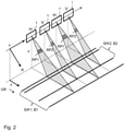
- FIG. 2 shows a schematic representation of the transmission of radar pulses by means of a variant of the SAR system according to the invention.
- the radar device 1 moves along the azimuth direction x at a height h above the earth's surface GR.
- the corresponding slant range or ground range is analogous to that in 1 indicated by coordinate axes R and y, respectively.
- In 2 shows the transmission of respective radar pulses at four consecutive points in time at different azimuth positions of the radar device 1 .
- the transmission of first radar pulses RP1 alternates with the transmission of second radar pulses RP2. This means that after a first radar pulse RP1 has been emitted, a second radar pulse RP2 is always emitted and vice versa.
- the first radar pulses RP1 are emitted as horizontally polarized waves, indicated by the reference H in 2 is clarified.
- the second radar pulses RP2 are emitted as vertically polarized waves, which is indicated by the reference symbol V in 2 is clarified.
- the radar echoes are also received both in the horizontal polarization H and in the vertical polarization V.
- the first and second radar pulses also differ in the radiation diagram used for their transmission.
- the radar pulses RP1 cover a strip SW1 with the width B1 on the earth's surface, whereas the second radar pulses RP2 only cover a strip SW2 with the smaller width B2.
- the strip SW2 lies within the strip SW1.
- a quad-polarimetric calculation is made using the radar echoes from strip SW2 Achieved data acquisition in which both the transmitted radar pulses with horizontal polarization and the transmitted radar pulses with vertical polarization are required. This results in a pulse repetition rate that is twice as high compared to data acquisitions that only take into account horizontally polarized or only vertically polarized radar pulses. Consequently, due to range ambiguities, only a narrow strip can be acquired with quad-polarimetric data acquisition.
- the embodiment of the method according to the invention described here is characterized in that single-polarimetric data or dual-polarimetric data for a wide strip SW1 can be obtained simultaneously with quad-polarimetric data for a narrower strip SW2.
- the radar pulses are transmitted as first or second radar pulses RP1 or RP2 with different radiation diagrams and suitable SAR raw data sets are obtained from the radar echoes of these radar pulses using digital beam shaping, with which both a single-polarimetric or dual-polarimetric Operating mode and a quad-polarimetric operating mode can be realized.
- FIG. 3 shows a diagram that shows different variants of obtaining SAR raw data sets for the realization of two polarimetric operating modes.
- the individual variants are denoted by VA1 to VA5.
- Variant VA1 and variant VA4 are particularly preferred.
- the detected stripe widths for the horizontally polarized radar pulses RP1 and the vertically polarized radar pulses RP2 are shown for the individual variants in column Tx and denoted by reference symbols H and V, respectively.
- a broad radar pulse with horizontal polarization H is emitted, followed by a narrow radar pulse with vertical polarization V.
- the transmission schemes of the individual variants differ in 3 are.
- the polarization channel P1 corresponds to the first polarization channel
- the polarization channel P2 to the second polarization channel
- the polarization channel P3 to the third polarization channel
- the polarization channel P4 to the fourth polarization channel.
- the bars shown next to the individual polarization channels represent the stripe width for which radar echoes are contained in the corresponding received polarization in the SAR raw data set under consideration.
- the bars are also provided with the corresponding reference symbols DS1, DS2, DS3 and DS4 to designate SAR raw data sets in addition to the designations of the reception polarizations H and V.
- the data set DS1 corresponds to the first SAR raw data set
- the data set DS2 to the second SAR raw data set
- the data set DS3 to the third SAR raw data set.
- the data set DS4 corresponds to a fourth raw SAR data set defined in some of the dependent claims.
- the individual polarization channels P1 to P4 are also labeled with their usual designations HH, VH, HV and VV.
- HH means horizontal transmission polarization and horizontal reception polarization
- the first polarization channel P1 and the fourth polarization channel P4 are co-polar polarization channels
- the second polarization channel P2 and the third polarization channel P3 are cross-polar polarization channels.
- raw SAR data sets DS1 and DS2 are obtained for the entire first width of the two polarization channels P1 and P2. Furthermore, SAR raw data sets DS3 and DS4 are obtained for the entire second width of the polarization channels P3 and P4. In this way one obtains both dual-polarimetric data for the entire first latitude and quad-polarimetric data with both cross-polar channels P2 and P3 for the entire second width. As a result, a dual-polarimetric operating mode is implemented with a quad-polarimetric operating mode.
- the quad-polarimetric mode of operation has high data quality due to the use of two cross-polar channels, which are usually suitably merged.
- a raw SAR data set DS1 is obtained for the entire first width in the copolar polarization channel P1.
- a single-polarimetric operating mode is thereby implemented.
- a quad-polarimetric mode of operation for the second latitude is realized, which comprises only one cross-polar polarization channel P3.
- This quad-polarimetric data acquisition has a lower quality compared to the use of two cross-polar polarization channels, but it also requires less raw SAR data, which means that the amount of data to be transmitted to a ground station can be reduced.
- a dual-polarimetric operating mode is realized by considering the two polarization channels P1 and P2 for the entire first width. Furthermore, a quad-polarimetric operating mode is realized with only one cross-polar polarization channel P2 for the entire second width.
- a single-polarimetric mode of operation with the co-polar polarization channel P1 for the entire first width is realized in combination with a quad-polarimetric mode of operation with four polarization channels for the entire second width.
- variant VA5 which also corresponds to the embodiment according to patent claim 8
- a single-polarimetric operating mode in combination with a quad-polarimetric operating mode is again used analogously to variant VA4 four polarization channels.
- the single-polarimetric operating mode now contains the cross-polar polarization channel P2.
- the inventors have, among other things, the variant of the VA4 3 simulated based on data from a known SAR system.
- This system is based on the planned Tandem-L mission and uses a reflector antenna with a variety of feeds.
- the radar pulses are transmitted with a variable pulse repetition rate.
- ASR ratio ambiguity-to-signal ratio
- the determined ASR ratio was compared with data obtained in a separate single-polarimetric mode of operation and a separate quad-polarimetric mode of operation with the SAR system. It could be demonstrated that the ASR ratio with simultaneous single-polarimetric and quad-polarimetric data acquisition is only slightly worse than the corresponding ASR ratio with separate single-polarimetric and quad-polarimetric data acquisition.
- a synthetic aperture radar method is created for the first time, in which single or dual polarimetric data are recorded together with polarimetric data from three or four polarization channels.
- the single- or dual-polarimetric data acquisition enables the acquisition of a strip with a greater width on the earth's surface than the polarimetric data acquisition from three or four polarization channels.
- radar pulses are transmitted in a first transmission polarization with an antenna diagram with a greater width in the range direction than radar pulses in a second transmission polarization.
- the SAR raw data obtained from the radar echoes are always selected in such a way that, in addition to simple or dual-polarimetric data for the wide strip, polarimetric data from three or four polarization channels for the narrower strip can also always be obtained.
Landscapes
- Engineering & Computer Science (AREA)
- Remote Sensing (AREA)
- Radar, Positioning & Navigation (AREA)
- Physics & Mathematics (AREA)
- Computer Networks & Wireless Communication (AREA)
- General Physics & Mathematics (AREA)
- Electromagnetism (AREA)
- Radar Systems Or Details Thereof (AREA)
Claims (12)
- Procédé de radar à synthèse d'ouverture pour la télédétection de la surface terrestre (GR) par le biais d'une installation radar (1) sur au moins un objet volant qui se déplace dans une direction azimutale (x) au-dessus de la surface terrestre (GR), dans lequel l'installation radar (1) émet dans le mode d'émission des impulsions radar (RP1, RP2) et reçoit dans le mode de réception les échos radar de ces impulsions radar (RP1, RP2) réfléchis sur la surface terrestre (GR), dans lequel- des premières et secondes impulsions radar (RP1, RP2) sont émises en alternance par l'installation radar (1) dans le mode d'émission à des instants d'émission successifs, dans lequel une première impulsion radar respective (RP1) présente une première polarisation d'émission (H) et est émise avec un diagramme de rayonnement qui couvre une première largeur (B1) sur la surface terrestre (GR) dans une direction de portée (y) perpendiculaire à la direction azimutale (x), et dans lequel une seconde impulsion radar respective (RP2) présente une seconde polarisation d'émission (V) qui est différente de la première polarisation d'émission (H), et est émise avec un diagramme de rayonnement qui couvre une seconde largeur (B2) sur la surface terrestre (GR) dans la direction de portée (y), dans lequel la première largeur (B1) correspond à un premier couloir (SW1) dans la direction azimutale (x) sur la surface terrestre (GR) et la seconde largeur (B2) correspond à un second couloir (SW2) dans la direction azimutale (x) sur la surface terrestre (GR), dans lequel le premier couloir (SW1) contient le second couloir entier (SW2) et la seconde largeur (B2) est inférieure à la première largeur (B1) ;- les échos radar des premières et secondes impulsions radar (RP1, RP2) sont reçus par l'installation radar (1) dans le mode de réception dans une première polarisation de réception (H) et dans une seconde polarisation de réception (V), moyennant quoi des premier à quatrième canaux de polarisation (P1, P2, P3, P4) sont formés, dans lequel le premier canal de polarisation (P1) contient les échos radar des premières impulsions radar (RP1) reçus dans la première polarisation de réception (H), le deuxième canal de polarisation (P2) contient les échos radar des premières impulsions radar (RP1) reçus dans la seconde polarisation de réception (V), le troisième canal de polarisation (P3) contient les échos radar des secondes impulsions radar (RP2) reçus dans la première polarisation de réception (H) et le quatrième canal de polarisation (P4) contient les échos radar des secondes impulsions radar (RP2) reçus dans la seconde polarisation de réception (V) ;- les échos radar reçus sont numérisés et plusieurs ensembles de données brutes de RSO (DS1, DS2, DS3, DS4) sont déterminés au moyen de formation de faisceau numérique à partir des échos radar reçus, lesquels comprennent au moins :i) un premier ensemble de données brutes de RSO (DS1) qui contient des échos radar d'un canal de polarisation (P1, P2) parmi une paire de canaux de polarisation (P1, P2) pour la première largeur entière (B1), dans lequel la paire de canaux de polarisation (P1, P2) comprend les premier et deuxième canaux de polarisation (P1, P2) ;ii) un deuxième ensemble de données brutes de RSO (DS2) qui contient soit les échos radar de l'autre canal de polarisation (P1, P2), non utilisé dans le premier ensemble de données brutes de RSO (DS1), parmi la paire de canaux de polarisation (P1, P2) pour la première largeur entière (B1), soit qui contient les échos radar du troisième canal de polarisation (P3) pour la seconde largeur entière (B2) ;iii) un troisième ensemble de données brutes de RSO qui contient les échos radar du quatrième canal de polarisation (P4) pour la seconde largeur entière (B2).
- Procédé selon la revendication 1, caractérisé en ce que la première polarisation d'émission (H) correspond à la première polarisation de réception (H) et la seconde polarisation d'émission (V) correspond à la seconde polarisation de réception (V).
- Procédé selon la revendication 1 ou 2, caractérisé en ce que la première polarisation d'émission (H) et la seconde polarisation d'émission (V) ainsi que la première polarisation de réception (H) et la seconde polarisation de réception (V) sont des polarisations linéaires, dans lequel la première polarisation d'émission (H) et la première polarisation de réception sont de préférence une polarisation horizontale, et la seconde polarisation d'émission (V) et la seconde polarisation de réception (V) sont de préférence une polarisation verticale.
- Procédé selon une des revendications précédentes, caractérisé en ce que la fréquence de répétition des impulsions des premières impulsions radar (RP1) et/ou des secondes impulsions radar varie.
- Procédé selon une des revendications précédentes, caractérisé en ce que la pluralité d'ensembles de données brutes de RSO (DS1, DS2, DS3, DS4) comprend exclusivement :- le premier ensemble de données brutes de RSO (DS1) qui contient des échos radar d'un canal de polarisation (P1, P2) parmi une paire de canaux de polarisation (P1, P2) pour la première largeur entière (B1), dans lequel la paire de canaux de polarisation (P1, P2) comprend les premier et deuxième canaux de polarisation (P1, P2) ;- le deuxième ensemble de données brutes de RSO (DS2) qui contient les échos radar de l'autre canal de polarisation (P1, P2), non utilisé dans le premier ensemble de données brutes de RSO (DS1), parmi la paire de canaux de polarisation (P1, P2) pour la première largeur entière (B1) ;- le troisième ensemble de données brutes de RSO (DS3) qui contient les échos radar du quatrième canal de polarisation (P4) pour la seconde largeur entière (B2) ;- un quatrième ensemble de données brutes de RSO qui contient les échos radar du troisième canal de polarisation (P3) pour la seconde largeur entière (B2).
- Procédé selon une des revendications 1 à 4, caractérisé en ce que la pluralité d'ensembles de données brutes de RSO (DS1, DS2, DS3, DS4) comprend exclusivement :- le premier ensemble de données brutes de RSO (DS1) qui contient des échos radar d'un canal de polarisation (P1, P2) parmi une paire de canaux de polarisation (P1, P2) pour la première largeur entière (B1), dans lequel la paire de canaux de polarisation (P1, P2) comprend les premier et deuxième canaux de polarisation (P1, P2) ;- le deuxième ensemble de données brutes de RSO (DS2) qui contient les échos radar du troisième canal de polarisation (P3) pour la seconde largeur entière (B2) ;- le troisième ensemble de données brutes de RSO (DS3) qui contient les échos radar du quatrième canal de polarisation (P4) pour la seconde largeur entière (B2).
- Procédé selon une des revendications 1 à 4, caractérisé en ce que la pluralité d'ensembles de données brutes de RSO (DS1, DS2, DS3, DS4) comprend exclusivement :- le premier ensemble de données brutes de RSO (DS1) qui contient des échos radar d'un canal de polarisation (P1, P2) parmi une paire de canaux de polarisation (P1, P2) pour la première largeur entière (B1), dans lequel la paire de canaux de polarisation (P1, P2) comprend les premier et deuxième canaux de polarisation (P1, P2) ;- le deuxième ensemble de données brutes de RSO (DS2) qui contient les échos radar de l'autre canal de polarisation (P1, P2), non utilisé dans le premier ensemble de données brutes de RSO (DS1), parmi la paire de canaux de polarisation (P1, P2) pour la première largeur entière (B1) ;- le troisième ensemble de données brutes de RSO (DS3) qui contient les échos radar du quatrième canal de polarisation (P4) pour la seconde largeur entière (B2).
- Procédé selon une des revendications 1 à 4, caractérisé en ce que la pluralité d'ensembles de données brutes de RSO (DS1, DS2, DS3, DS4) comprend exclusivement :- le premier ensemble de données brutes de RSO (DS1) qui contient des échos radar d'un canal de polarisation (P1, P2) parmi une paire de canaux de polarisation (P1, P2) pour la première largeur entière (B1), dans lequel la paire de canaux de polarisation (P1, P2) comprend les premier et deuxième canaux de polarisation (P1, P2) ;- le deuxième ensemble de données brutes de RSO (DS2) qui contient les échos radar du troisième canal de polarisation (P3) pour la seconde largeur entière (B2) ;- le troisième ensemble de données brutes de RSO (DS3) qui contient les échos radar du quatrième canal de polarisation (P4) pour la seconde largeur entière (B2) ;- un quatrième ensemble de données brutes de RSO (DS1) qui contient les échos radar de l'autre canal de polarisation (P1, P2), non utilisé dans le premier ensemble de données brutes de RSO (DS1), parmi la paire de canaux de polarisation (P1, P2) exclusivement pour la seconde largeur entière (B2).
- Procédé selon une des revendications précédentes, caractérisé en ce que l'émission des impulsions radar (RP1, RP2) et la réception des échos radar s'effectuent au moyen d'une installation radar (1) qui comprend une antenne à réflecteur avec un réflecteur et un réseau de plusieurs antennes d'alimentation et/ou une antenne planaire avec un réseau de plusieurs éléments d'antenne.
- Procédé selon une des revendications précédentes, caractérisé en ce que la pluralité d'ensembles de données brutes de RSO (DS1, DS2, DS3, DS4) est déterminée avec un dispositif informatique sur l'au moins un objet volant, puis est transmise à une station au sol sur la surface terrestre (GR).
- Dispositif radar à synthèse d'ouverture pour la télédétection de la surface terrestre (GR) par le biais d'une installation radar (1) sur au moins un objet volant qui se déplace dans une direction azimutale (x) au-dessus de la surface terrestre (GR), dans lequel l'installation radar (1) est paramétrée de telle sorte qu'elle émet dans le mode d'émission des impulsions radar et reçoit dans le mode de réception les échos radar de ces impulsions radar (RP) réfléchis sur la surface terrestre (GR), dans lequel le dispositif radar à synthèse d'ouverture est configuré de telle sorte que- des premières et secondes impulsions radar (RP1, RP2) sont émises en alternance par l'installation radar (1) dans le mode d'émission à des instants d'émission successifs, dans lequel une première impulsion radar respective (RP1) présente une première polarisation d'émission (H) et est émise avec un diagramme de rayonnement qui couvre une première largeur (B1) sur la surface terrestre (GR) dans une direction de portée (y) perpendiculaire à la direction azimutale (x), et dans lequel une seconde impulsion radar respective (RP2) présente une seconde polarisation d'émission (V) qui est différente de la première polarisation d'émission (H), et est émise avec un diagramme de rayonnement qui couvre une seconde largeur (B2) sur la surface terrestre (GR) dans la direction de portée (y), dans lequel la première largeur correspond à un premier couloir (SW1) dans la direction azimutale (x) sur la surface terrestre (GR) et la seconde largeur (B2) correspond à un second couloir (SW2) dans la direction azimutale (x) sur la surface terrestre (GR), dans lequel le premier couloir (SW1) contient le second couloir entier (SW2) et la seconde largeur (B2) est inférieure à la première largeur (B1) ;- les échos radar des premières et secondes impulsions radar (RP1, RP2) sont reçus par l'installation radar (1) dans le mode de réception aussi bien dans une première polarisation de réception (H) que dans une seconde polarisation de réception (V), moyennant quoi des premier à quatrième canaux de polarisation (P1, P2, P3, P4) sont formés, dans lequel le premier canal de polarisation (P1) contient les échos radar des premières impulsions radar (RP1) reçus dans la première polarisation de réception (H), le deuxième canal de polarisation (P2) contient les échos radar des premières impulsions radar (RP1) reçus dans la seconde polarisation de réception (V), le troisième canal de polarisation (P3) contient les échos radar des secondes impulsions radar (RP2) reçus dans la première polarisation de réception (H) et le quatrième canal de polarisation (P4) contient les échos radar des secondes impulsions radar (RP2) reçus dans la seconde polarisation de réception (V) ;- les échos radar reçus sont numérisés et plusieurs ensembles de données brutes de RSO (DS1, DS12, ..., DS4) sont déterminés au moyen de formation de faisceau numérique à partir des échos radar reçus, lesquels comprennent au moins :i) un premier ensemble de données brutes de RSO (DS1) qui contient des échos radar d'un canal de polarisation (P1, P2) parmi une paire de canaux de polarisation (P1, P2) pour la première largeur entière (B1), dans lequel la paire de canaux de polarisation (P1, P2) comprend les premier et deuxième canaux de polarisation (P1, P2) ;ii) un deuxième ensemble de données brutes de RSO (DS2) qui contient soit les échos radar de l'autre canal de polarisation (P1, P2), non utilisé dans le premier ensemble de données brutes de RSO (DS1), parmi la paire de canaux de polarisation (P1, P2) pour la première largeur entière (B1), soit qui contient les échos radar du troisième canal de polarisation (P3) pour la seconde largeur entière (B2) ;iii) un troisième ensemble de données brutes de RSO qui contient les échos radar du quatrième canal de polarisation (P4) pour la seconde largeur entière (B2).
- Dispositif selon la revendication 11, caractérisé en ce que le dispositif est agencé pour la réalisation d'un procédé selon une des revendications 2 à 10.
Applications Claiming Priority (1)
| Application Number | Priority Date | Filing Date | Title |
|---|---|---|---|
| DE102018206670.1A DE102018206670B3 (de) | 2018-04-30 | 2018-04-30 | Synthetik-Apertur-Radarverfahren zur Fernerkundung der Erdoberfläche und Synthetik-Apertur-Radarvorrichtung |
Publications (3)
| Publication Number | Publication Date |
|---|---|
| EP3564708A1 EP3564708A1 (fr) | 2019-11-06 |
| EP3564708B1 true EP3564708B1 (fr) | 2022-03-16 |
| EP3564708B8 EP3564708B8 (fr) | 2022-04-20 |
Family
ID=66251650
Family Applications (1)
| Application Number | Title | Priority Date | Filing Date |
|---|---|---|---|
| EP19170782.7A Active EP3564708B8 (fr) | 2018-04-30 | 2019-04-24 | Procédé radar à synthèse d'ouverture permettant de télédétecter la surface de la terre et dispositif radar à synthèse d'ouverture |
Country Status (3)
| Country | Link |
|---|---|
| EP (1) | EP3564708B8 (fr) |
| DE (1) | DE102018206670B3 (fr) |
| ES (1) | ES2913152T3 (fr) |
Family Cites Families (2)
| Publication number | Priority date | Publication date | Assignee | Title |
|---|---|---|---|---|
| CN103885052B (zh) * | 2014-03-25 | 2016-05-04 | 西安空间无线电技术研究所 | 一种宽幅全极化星载sar的极化回波分离方法 |
| US20180335518A1 (en) | 2014-08-08 | 2018-11-22 | Urthecast Corp. | Apparatus and methods for quad-polarized synthetic aperture radar |
-
2018
- 2018-04-30 DE DE102018206670.1A patent/DE102018206670B3/de active Active
-
2019
- 2019-04-24 EP EP19170782.7A patent/EP3564708B8/fr active Active
- 2019-04-24 ES ES19170782T patent/ES2913152T3/es active Active
Also Published As
| Publication number | Publication date |
|---|---|
| DE102018206670B3 (de) | 2019-05-23 |
| EP3564708B8 (fr) | 2022-04-20 |
| EP3564708A1 (fr) | 2019-11-06 |
| ES2913152T3 (es) | 2022-05-31 |
Similar Documents
| Publication | Publication Date | Title |
|---|---|---|
| EP3803454B1 (fr) | Procédé radar à ouverture synthetique et dispositif radar à ouverture synthetique | |
| EP1966630B1 (fr) | Dispositif radar à ouverture synthetique haute résolution, et antenne pour un tel dispositif radar | |
| EP2018577B1 (fr) | Système radar haute résolution à visée latérale et à ouverture synthétique utilisant une mise en forme de faisceau numérique | |
| EP2725382B1 (fr) | Radar à ouverture synthétique pour la prise de vue et la détection de cible mobile simultanées | |
| EP2191297B1 (fr) | Procédé faisant appel à un radar à synthèse d'ouverture | |
| DE3885891T2 (de) | Unterdrückung von azimutaler mehrdeutigkeit im sar-signal. | |
| DE102011083756A1 (de) | Radar-Vorrichtung und Verfahren zum Erzeugen einer Gruppencharakteristik eines Radars | |
| EP3060939B1 (fr) | Procédé radar à synthèse d'ouverture | |
| EP3244231A1 (fr) | Systeme d'antenne mimo et procede d'imagerie radar tridimensionnelle | |
| EP2722686B1 (fr) | Système sar interférométrique | |
| DE102013216461A1 (de) | Synthetik-Apertur-Radarverfahren | |
| EP0487940B1 (fr) | Radar du type pulsdoppler | |
| EP3564708B1 (fr) | Procédé radar à synthèse d'ouverture permettant de télédétecter la surface de la terre et dispositif radar à synthèse d'ouverture | |
| DE2440742C3 (de) | Einrichtung zur Ausschaltung von Stör- und Festzeichen | |
| EP2722685B1 (fr) | Procédé de radar à ouverture synthétique | |
| WO2021213843A1 (fr) | Procédé associé à un radar et système radar d'analyse à cohérence de phase | |
| EP3249426B1 (fr) | Procédé de radar à synthèse d'ouverture | |
| DE102016224962B3 (de) | Synthetik-Apertur-Radarverfahren und Synthetik-Apertur-Radarsystem | |
| EP2775317B1 (fr) | Procédé de fonctionnement d'un système radar avec ouverture synthétique en mode d'émission et de réception | |
| DE102018120383A1 (de) | Radarsystem mit einer synthetischen Antennenapertur |
Legal Events
| Date | Code | Title | Description |
|---|---|---|---|
| PUAI | Public reference made under article 153(3) epc to a published international application that has entered the european phase |
Free format text: ORIGINAL CODE: 0009012 |
|
| STAA | Information on the status of an ep patent application or granted ep patent |
Free format text: STATUS: THE APPLICATION HAS BEEN PUBLISHED |
|
| AK | Designated contracting states |
Kind code of ref document: A1 Designated state(s): AL AT BE BG CH CY CZ DE DK EE ES FI FR GB GR HR HU IE IS IT LI LT LU LV MC MK MT NL NO PL PT RO RS SE SI SK SM TR |
|
| AX | Request for extension of the european patent |
Extension state: BA ME |
|
| STAA | Information on the status of an ep patent application or granted ep patent |
Free format text: STATUS: REQUEST FOR EXAMINATION WAS MADE |
|
| 17P | Request for examination filed |
Effective date: 20200414 |
|
| RBV | Designated contracting states (corrected) |
Designated state(s): AL AT BE BG CH CY CZ DE DK EE ES FI FR GB GR HR HU IE IS IT LI LT LU LV MC MK MT NL NO PL PT RO RS SE SI SK SM TR |
|
| RIC1 | Information provided on ipc code assigned before grant |
Ipc: G01S 13/90 20060101AFI20210915BHEP |
|
| GRAP | Despatch of communication of intention to grant a patent |
Free format text: ORIGINAL CODE: EPIDOSNIGR1 |
|
| STAA | Information on the status of an ep patent application or granted ep patent |
Free format text: STATUS: GRANT OF PATENT IS INTENDED |
|
| INTG | Intention to grant announced |
Effective date: 20211022 |
|
| GRAS | Grant fee paid |
Free format text: ORIGINAL CODE: EPIDOSNIGR3 |
|
| GRAA | (expected) grant |
Free format text: ORIGINAL CODE: 0009210 |
|
| STAA | Information on the status of an ep patent application or granted ep patent |
Free format text: STATUS: THE PATENT HAS BEEN GRANTED |
|
| REG | Reference to a national code |
Ref country code: DE Ref legal event code: R108 Ref document number: 502019003697 Country of ref document: DE |
|
| AK | Designated contracting states |
Kind code of ref document: B1 Designated state(s): AL AT BE BG CH CY CZ DE DK EE ES FI FR GB GR HR HU IE IS IT LI LT LU LV MC MK MT NL NO PL PT RO RS SE SI SK SM TR |
|
| REG | Reference to a national code |
Ref country code: GB Ref legal event code: FG4D Free format text: NOT ENGLISH |
|
| REG | Reference to a national code |
Ref country code: CH Ref legal event code: PK Free format text: BERICHTIGUNG B8 Ref country code: CH Ref legal event code: EP |
|
| RBV | Designated contracting states (corrected) |
Designated state(s): AL AT BE BG CH CY CZ DK EE ES FI FR GB GR HR HU IE IS IT LI LT LU LV MC MK MT NL NO PL PT RO RS SE SI SK SM TR |
|
| REG | Reference to a national code |
Ref country code: IE Ref legal event code: FG4D Free format text: LANGUAGE OF EP DOCUMENT: GERMAN |
|
| REG | Reference to a national code |
Ref country code: AT Ref legal event code: REF Ref document number: 1476287 Country of ref document: AT Kind code of ref document: T Effective date: 20220415 |
|
| REG | Reference to a national code |
Ref country code: DE Ref legal event code: R107 Ref document number: 502019003697 Country of ref document: DE |
|
| REG | Reference to a national code |
Ref country code: ES Ref legal event code: FG2A Ref document number: 2913152 Country of ref document: ES Kind code of ref document: T3 Effective date: 20220531 |
|
| REG | Reference to a national code |
Ref country code: LT Ref legal event code: MG9D |
|
| REG | Reference to a national code |
Ref country code: NL Ref legal event code: MP Effective date: 20220316 |
|
| PG25 | Lapsed in a contracting state [announced via postgrant information from national office to epo] |
Ref country code: SE Free format text: LAPSE BECAUSE OF FAILURE TO SUBMIT A TRANSLATION OF THE DESCRIPTION OR TO PAY THE FEE WITHIN THE PRESCRIBED TIME-LIMIT Effective date: 20220316 Ref country code: RS Free format text: LAPSE BECAUSE OF FAILURE TO SUBMIT A TRANSLATION OF THE DESCRIPTION OR TO PAY THE FEE WITHIN THE PRESCRIBED TIME-LIMIT Effective date: 20220316 Ref country code: NO Free format text: LAPSE BECAUSE OF FAILURE TO SUBMIT A TRANSLATION OF THE DESCRIPTION OR TO PAY THE FEE WITHIN THE PRESCRIBED TIME-LIMIT Effective date: 20220616 Ref country code: LT Free format text: LAPSE BECAUSE OF FAILURE TO SUBMIT A TRANSLATION OF THE DESCRIPTION OR TO PAY THE FEE WITHIN THE PRESCRIBED TIME-LIMIT Effective date: 20220316 Ref country code: HR Free format text: LAPSE BECAUSE OF FAILURE TO SUBMIT A TRANSLATION OF THE DESCRIPTION OR TO PAY THE FEE WITHIN THE PRESCRIBED TIME-LIMIT Effective date: 20220316 Ref country code: BG Free format text: LAPSE BECAUSE OF FAILURE TO SUBMIT A TRANSLATION OF THE DESCRIPTION OR TO PAY THE FEE WITHIN THE PRESCRIBED TIME-LIMIT Effective date: 20220616 |
|
| PG25 | Lapsed in a contracting state [announced via postgrant information from national office to epo] |
Ref country code: LV Free format text: LAPSE BECAUSE OF FAILURE TO SUBMIT A TRANSLATION OF THE DESCRIPTION OR TO PAY THE FEE WITHIN THE PRESCRIBED TIME-LIMIT Effective date: 20220316 Ref country code: GR Free format text: LAPSE BECAUSE OF FAILURE TO SUBMIT A TRANSLATION OF THE DESCRIPTION OR TO PAY THE FEE WITHIN THE PRESCRIBED TIME-LIMIT Effective date: 20220617 Ref country code: FI Free format text: LAPSE BECAUSE OF FAILURE TO SUBMIT A TRANSLATION OF THE DESCRIPTION OR TO PAY THE FEE WITHIN THE PRESCRIBED TIME-LIMIT Effective date: 20220316 |
|
| PG25 | Lapsed in a contracting state [announced via postgrant information from national office to epo] |
Ref country code: NL Free format text: LAPSE BECAUSE OF FAILURE TO SUBMIT A TRANSLATION OF THE DESCRIPTION OR TO PAY THE FEE WITHIN THE PRESCRIBED TIME-LIMIT Effective date: 20220316 |
|
| PG25 | Lapsed in a contracting state [announced via postgrant information from national office to epo] |
Ref country code: SM Free format text: LAPSE BECAUSE OF FAILURE TO SUBMIT A TRANSLATION OF THE DESCRIPTION OR TO PAY THE FEE WITHIN THE PRESCRIBED TIME-LIMIT Effective date: 20220316 Ref country code: SK Free format text: LAPSE BECAUSE OF FAILURE TO SUBMIT A TRANSLATION OF THE DESCRIPTION OR TO PAY THE FEE WITHIN THE PRESCRIBED TIME-LIMIT Effective date: 20220316 Ref country code: RO Free format text: LAPSE BECAUSE OF FAILURE TO SUBMIT A TRANSLATION OF THE DESCRIPTION OR TO PAY THE FEE WITHIN THE PRESCRIBED TIME-LIMIT Effective date: 20220316 Ref country code: PT Free format text: LAPSE BECAUSE OF FAILURE TO SUBMIT A TRANSLATION OF THE DESCRIPTION OR TO PAY THE FEE WITHIN THE PRESCRIBED TIME-LIMIT Effective date: 20220718 Ref country code: EE Free format text: LAPSE BECAUSE OF FAILURE TO SUBMIT A TRANSLATION OF THE DESCRIPTION OR TO PAY THE FEE WITHIN THE PRESCRIBED TIME-LIMIT Effective date: 20220316 Ref country code: CZ Free format text: LAPSE BECAUSE OF FAILURE TO SUBMIT A TRANSLATION OF THE DESCRIPTION OR TO PAY THE FEE WITHIN THE PRESCRIBED TIME-LIMIT Effective date: 20220316 |
|
| PG25 | Lapsed in a contracting state [announced via postgrant information from national office to epo] |
Ref country code: PL Free format text: LAPSE BECAUSE OF FAILURE TO SUBMIT A TRANSLATION OF THE DESCRIPTION OR TO PAY THE FEE WITHIN THE PRESCRIBED TIME-LIMIT Effective date: 20220316 Ref country code: IS Free format text: LAPSE BECAUSE OF FAILURE TO SUBMIT A TRANSLATION OF THE DESCRIPTION OR TO PAY THE FEE WITHIN THE PRESCRIBED TIME-LIMIT Effective date: 20220716 Ref country code: AL Free format text: LAPSE BECAUSE OF FAILURE TO SUBMIT A TRANSLATION OF THE DESCRIPTION OR TO PAY THE FEE WITHIN THE PRESCRIBED TIME-LIMIT Effective date: 20220316 |
|
| REG | Reference to a national code |
Ref country code: CH Ref legal event code: PL |
|
| REG | Reference to a national code |
Ref country code: BE Ref legal event code: MM Effective date: 20220430 |
|
| PLBE | No opposition filed within time limit |
Free format text: ORIGINAL CODE: 0009261 |
|
| STAA | Information on the status of an ep patent application or granted ep patent |
Free format text: STATUS: NO OPPOSITION FILED WITHIN TIME LIMIT |
|
| PG25 | Lapsed in a contracting state [announced via postgrant information from national office to epo] |
Ref country code: MC Free format text: LAPSE BECAUSE OF FAILURE TO SUBMIT A TRANSLATION OF THE DESCRIPTION OR TO PAY THE FEE WITHIN THE PRESCRIBED TIME-LIMIT Effective date: 20220316 Ref country code: LU Free format text: LAPSE BECAUSE OF NON-PAYMENT OF DUE FEES Effective date: 20220424 Ref country code: LI Free format text: LAPSE BECAUSE OF NON-PAYMENT OF DUE FEES Effective date: 20220430 Ref country code: DK Free format text: LAPSE BECAUSE OF FAILURE TO SUBMIT A TRANSLATION OF THE DESCRIPTION OR TO PAY THE FEE WITHIN THE PRESCRIBED TIME-LIMIT Effective date: 20220316 Ref country code: CH Free format text: LAPSE BECAUSE OF NON-PAYMENT OF DUE FEES Effective date: 20220430 |
|
| 26N | No opposition filed |
Effective date: 20221219 |
|
| PG25 | Lapsed in a contracting state [announced via postgrant information from national office to epo] |
Ref country code: SI Free format text: LAPSE BECAUSE OF FAILURE TO SUBMIT A TRANSLATION OF THE DESCRIPTION OR TO PAY THE FEE WITHIN THE PRESCRIBED TIME-LIMIT Effective date: 20220316 Ref country code: BE Free format text: LAPSE BECAUSE OF NON-PAYMENT OF DUE FEES Effective date: 20220430 |
|
| PG25 | Lapsed in a contracting state [announced via postgrant information from national office to epo] |
Ref country code: IE Free format text: LAPSE BECAUSE OF NON-PAYMENT OF DUE FEES Effective date: 20220424 |
|
| PG25 | Lapsed in a contracting state [announced via postgrant information from national office to epo] |
Ref country code: HU Free format text: LAPSE BECAUSE OF FAILURE TO SUBMIT A TRANSLATION OF THE DESCRIPTION OR TO PAY THE FEE WITHIN THE PRESCRIBED TIME-LIMIT; INVALID AB INITIO Effective date: 20190424 |
|
| PG25 | Lapsed in a contracting state [announced via postgrant information from national office to epo] |
Ref country code: MK Free format text: LAPSE BECAUSE OF FAILURE TO SUBMIT A TRANSLATION OF THE DESCRIPTION OR TO PAY THE FEE WITHIN THE PRESCRIBED TIME-LIMIT Effective date: 20220316 Ref country code: CY Free format text: LAPSE BECAUSE OF FAILURE TO SUBMIT A TRANSLATION OF THE DESCRIPTION OR TO PAY THE FEE WITHIN THE PRESCRIBED TIME-LIMIT Effective date: 20220316 |
|
| PGFP | Annual fee paid to national office [announced via postgrant information from national office to epo] |
Ref country code: GB Payment date: 20240314 Year of fee payment: 6 |
|
| PGFP | Annual fee paid to national office [announced via postgrant information from national office to epo] |
Ref country code: FR Payment date: 20240315 Year of fee payment: 6 |
|
| PG25 | Lapsed in a contracting state [announced via postgrant information from national office to epo] |
Ref country code: TR Free format text: LAPSE BECAUSE OF FAILURE TO SUBMIT A TRANSLATION OF THE DESCRIPTION OR TO PAY THE FEE WITHIN THE PRESCRIBED TIME-LIMIT Effective date: 20220316 |
|
| PGFP | Annual fee paid to national office [announced via postgrant information from national office to epo] |
Ref country code: ES Payment date: 20240510 Year of fee payment: 6 |
|
| PGFP | Annual fee paid to national office [announced via postgrant information from national office to epo] |
Ref country code: IT Payment date: 20240410 Year of fee payment: 6 |
|
| PG25 | Lapsed in a contracting state [announced via postgrant information from national office to epo] |
Ref country code: MT Free format text: LAPSE BECAUSE OF FAILURE TO SUBMIT A TRANSLATION OF THE DESCRIPTION OR TO PAY THE FEE WITHIN THE PRESCRIBED TIME-LIMIT Effective date: 20220316 |