EP3003717B1 - Artikel und verfahren zum einwickeln eines substrats mit einer polymerstruktur - Google Patents
Artikel und verfahren zum einwickeln eines substrats mit einer polymerstruktur Download PDFInfo
- Publication number
- EP3003717B1 EP3003717B1 EP14732810.8A EP14732810A EP3003717B1 EP 3003717 B1 EP3003717 B1 EP 3003717B1 EP 14732810 A EP14732810 A EP 14732810A EP 3003717 B1 EP3003717 B1 EP 3003717B1
- Authority
- EP
- European Patent Office
- Prior art keywords
- polymeric structure
- substrate
- polymeric
- layer
- crosslinked
- Prior art date
- Legal status (The legal status is an assumption and is not a legal conclusion. Google has not performed a legal analysis and makes no representation as to the accuracy of the status listed.)
- Active
Links
Images


Classifications
-
- F—MECHANICAL ENGINEERING; LIGHTING; HEATING; WEAPONS; BLASTING
- F16—ENGINEERING ELEMENTS AND UNITS; GENERAL MEASURES FOR PRODUCING AND MAINTAINING EFFECTIVE FUNCTIONING OF MACHINES OR INSTALLATIONS; THERMAL INSULATION IN GENERAL
- F16L—PIPES; JOINTS OR FITTINGS FOR PIPES; SUPPORTS FOR PIPES, CABLES OR PROTECTIVE TUBING; MEANS FOR THERMAL INSULATION IN GENERAL
- F16L5/00—Devices for use where pipes, cables or protective tubing pass through walls or partitions
- F16L5/02—Sealing
-
- B—PERFORMING OPERATIONS; TRANSPORTING
- B29—WORKING OF PLASTICS; WORKING OF SUBSTANCES IN A PLASTIC STATE IN GENERAL
- B29C—SHAPING OR JOINING OF PLASTICS; SHAPING OF MATERIAL IN A PLASTIC STATE, NOT OTHERWISE PROVIDED FOR; AFTER-TREATMENT OF THE SHAPED PRODUCTS, e.g. REPAIRING
- B29C65/00—Joining or sealing of preformed parts, e.g. welding of plastics materials; Apparatus therefor
- B29C65/48—Joining or sealing of preformed parts, e.g. welding of plastics materials; Apparatus therefor using adhesives, i.e. using supplementary joining material; solvent bonding
-
- B—PERFORMING OPERATIONS; TRANSPORTING
- B29—WORKING OF PLASTICS; WORKING OF SUBSTANCES IN A PLASTIC STATE IN GENERAL
- B29C—SHAPING OR JOINING OF PLASTICS; SHAPING OF MATERIAL IN A PLASTIC STATE, NOT OTHERWISE PROVIDED FOR; AFTER-TREATMENT OF THE SHAPED PRODUCTS, e.g. REPAIRING
- B29C66/00—General aspects of processes or apparatus for joining preformed parts
- B29C66/50—General aspects of joining tubular articles; General aspects of joining long products, i.e. bars or profiled elements; General aspects of joining single elements to tubular articles, hollow articles or bars; General aspects of joining several hollow-preforms to form hollow or tubular articles
- B29C66/51—Joining tubular articles, profiled elements or bars; Joining single elements to tubular articles, hollow articles or bars; Joining several hollow-preforms to form hollow or tubular articles
- B29C66/53—Joining single elements to tubular articles, hollow articles or bars
- B29C66/532—Joining single elements to the wall of tubular articles, hollow articles or bars
-
- B—PERFORMING OPERATIONS; TRANSPORTING
- B29—WORKING OF PLASTICS; WORKING OF SUBSTANCES IN A PLASTIC STATE IN GENERAL
- B29C—SHAPING OR JOINING OF PLASTICS; SHAPING OF MATERIAL IN A PLASTIC STATE, NOT OTHERWISE PROVIDED FOR; AFTER-TREATMENT OF THE SHAPED PRODUCTS, e.g. REPAIRING
- B29C66/00—General aspects of processes or apparatus for joining preformed parts
- B29C66/70—General aspects of processes or apparatus for joining preformed parts characterised by the composition, physical properties or the structure of the material of the parts to be joined; Joining with non-plastics material
- B29C66/74—Joining plastics material to non-plastics material
-
- B—PERFORMING OPERATIONS; TRANSPORTING
- B29—WORKING OF PLASTICS; WORKING OF SUBSTANCES IN A PLASTIC STATE IN GENERAL
- B29D—PRODUCING PARTICULAR ARTICLES FROM PLASTICS OR FROM SUBSTANCES IN A PLASTIC STATE
- B29D99/00—Subject matter not provided for in other groups of this subclass
- B29D99/0082—Producing articles in the form of closed loops, e.g. rings
- B29D99/0085—Producing articles in the form of closed loops, e.g. rings for sealing purposes
-
- B—PERFORMING OPERATIONS; TRANSPORTING
- B32—LAYERED PRODUCTS
- B32B—LAYERED PRODUCTS, i.e. PRODUCTS BUILT-UP OF STRATA OF FLAT OR NON-FLAT, e.g. CELLULAR OR HONEYCOMB, FORM
- B32B27/00—Layered products comprising a layer of synthetic resin
- B32B27/06—Layered products comprising a layer of synthetic resin as the main or only constituent of a layer, which is next to another layer of the same or of a different material
- B32B27/08—Layered products comprising a layer of synthetic resin as the main or only constituent of a layer, which is next to another layer of the same or of a different material of synthetic resin
-
- B—PERFORMING OPERATIONS; TRANSPORTING
- B32—LAYERED PRODUCTS
- B32B—LAYERED PRODUCTS, i.e. PRODUCTS BUILT-UP OF STRATA OF FLAT OR NON-FLAT, e.g. CELLULAR OR HONEYCOMB, FORM
- B32B7/00—Layered products characterised by the relation between layers; Layered products characterised by the relative orientation of features between layers, or by the relative values of a measurable parameter between layers, i.e. products comprising layers having different physical, chemical or physicochemical properties; Layered products characterised by the interconnection of layers
- B32B7/04—Interconnection of layers
- B32B7/12—Interconnection of layers using interposed adhesives or interposed materials with bonding properties
-
- C—CHEMISTRY; METALLURGY
- C09—DYES; PAINTS; POLISHES; NATURAL RESINS; ADHESIVES; COMPOSITIONS NOT OTHERWISE PROVIDED FOR; APPLICATIONS OF MATERIALS NOT OTHERWISE PROVIDED FOR
- C09J—ADHESIVES; NON-MECHANICAL ASPECTS OF ADHESIVE PROCESSES IN GENERAL; ADHESIVE PROCESSES NOT PROVIDED FOR ELSEWHERE; USE OF MATERIALS AS ADHESIVES
- C09J7/00—Adhesives in the form of films or foils
- C09J7/20—Adhesives in the form of films or foils characterised by their carriers
- C09J7/22—Plastics; Metallised plastics
-
- C—CHEMISTRY; METALLURGY
- C09—DYES; PAINTS; POLISHES; NATURAL RESINS; ADHESIVES; COMPOSITIONS NOT OTHERWISE PROVIDED FOR; APPLICATIONS OF MATERIALS NOT OTHERWISE PROVIDED FOR
- C09J—ADHESIVES; NON-MECHANICAL ASPECTS OF ADHESIVE PROCESSES IN GENERAL; ADHESIVE PROCESSES NOT PROVIDED FOR ELSEWHERE; USE OF MATERIALS AS ADHESIVES
- C09J7/00—Adhesives in the form of films or foils
- C09J7/30—Adhesives in the form of films or foils characterised by the adhesive composition
- C09J7/35—Heat-activated
-
- C—CHEMISTRY; METALLURGY
- C09—DYES; PAINTS; POLISHES; NATURAL RESINS; ADHESIVES; COMPOSITIONS NOT OTHERWISE PROVIDED FOR; APPLICATIONS OF MATERIALS NOT OTHERWISE PROVIDED FOR
- C09J—ADHESIVES; NON-MECHANICAL ASPECTS OF ADHESIVE PROCESSES IN GENERAL; ADHESIVE PROCESSES NOT PROVIDED FOR ELSEWHERE; USE OF MATERIALS AS ADHESIVES
- C09J7/00—Adhesives in the form of films or foils
- C09J7/30—Adhesives in the form of films or foils characterised by the adhesive composition
- C09J7/38—Pressure-sensitive adhesives [PSA]
-
- F—MECHANICAL ENGINEERING; LIGHTING; HEATING; WEAPONS; BLASTING
- F16—ENGINEERING ELEMENTS AND UNITS; GENERAL MEASURES FOR PRODUCING AND MAINTAINING EFFECTIVE FUNCTIONING OF MACHINES OR INSTALLATIONS; THERMAL INSULATION IN GENERAL
- F16L—PIPES; JOINTS OR FITTINGS FOR PIPES; SUPPORTS FOR PIPES, CABLES OR PROTECTIVE TUBING; MEANS FOR THERMAL INSULATION IN GENERAL
- F16L5/00—Devices for use where pipes, cables or protective tubing pass through walls or partitions
- F16L5/02—Sealing
- F16L5/10—Sealing by using sealing rings or sleeves only
-
- B—PERFORMING OPERATIONS; TRANSPORTING
- B29—WORKING OF PLASTICS; WORKING OF SUBSTANCES IN A PLASTIC STATE IN GENERAL
- B29K—INDEXING SCHEME ASSOCIATED WITH SUBCLASSES B29B, B29C OR B29D, RELATING TO MOULDING MATERIALS OR TO MATERIALS FOR MOULDS, REINFORCEMENTS, FILLERS OR PREFORMED PARTS, e.g. INSERTS
- B29K2101/00—Use of unspecified macromolecular compounds as moulding material
-
- B—PERFORMING OPERATIONS; TRANSPORTING
- B29—WORKING OF PLASTICS; WORKING OF SUBSTANCES IN A PLASTIC STATE IN GENERAL
- B29L—INDEXING SCHEME ASSOCIATED WITH SUBCLASS B29C, RELATING TO PARTICULAR ARTICLES
- B29L2031/00—Other particular articles
- B29L2031/26—Sealing devices, e.g. packaging for pistons or pipe joints
-
- B—PERFORMING OPERATIONS; TRANSPORTING
- B32—LAYERED PRODUCTS
- B32B—LAYERED PRODUCTS, i.e. PRODUCTS BUILT-UP OF STRATA OF FLAT OR NON-FLAT, e.g. CELLULAR OR HONEYCOMB, FORM
- B32B2405/00—Adhesive articles, e.g. adhesive tapes
-
- B—PERFORMING OPERATIONS; TRANSPORTING
- B32—LAYERED PRODUCTS
- B32B—LAYERED PRODUCTS, i.e. PRODUCTS BUILT-UP OF STRATA OF FLAT OR NON-FLAT, e.g. CELLULAR OR HONEYCOMB, FORM
- B32B2581/00—Seals; Sealing equipment; Gaskets
-
- C—CHEMISTRY; METALLURGY
- C09—DYES; PAINTS; POLISHES; NATURAL RESINS; ADHESIVES; COMPOSITIONS NOT OTHERWISE PROVIDED FOR; APPLICATIONS OF MATERIALS NOT OTHERWISE PROVIDED FOR
- C09J—ADHESIVES; NON-MECHANICAL ASPECTS OF ADHESIVE PROCESSES IN GENERAL; ADHESIVE PROCESSES NOT PROVIDED FOR ELSEWHERE; USE OF MATERIALS AS ADHESIVES
- C09J2301/00—Additional features of adhesives in the form of films or foils
- C09J2301/10—Additional features of adhesives in the form of films or foils characterized by the structural features of the adhesive tape or sheet
- C09J2301/12—Additional features of adhesives in the form of films or foils characterized by the structural features of the adhesive tape or sheet by the arrangement of layers
- C09J2301/124—Additional features of adhesives in the form of films or foils characterized by the structural features of the adhesive tape or sheet by the arrangement of layers the adhesive layer being present on both sides of the carrier, e.g. double-sided adhesive tape
- C09J2301/1242—Additional features of adhesives in the form of films or foils characterized by the structural features of the adhesive tape or sheet by the arrangement of layers the adhesive layer being present on both sides of the carrier, e.g. double-sided adhesive tape the opposite adhesive layers being different
-
- C—CHEMISTRY; METALLURGY
- C09—DYES; PAINTS; POLISHES; NATURAL RESINS; ADHESIVES; COMPOSITIONS NOT OTHERWISE PROVIDED FOR; APPLICATIONS OF MATERIALS NOT OTHERWISE PROVIDED FOR
- C09J—ADHESIVES; NON-MECHANICAL ASPECTS OF ADHESIVE PROCESSES IN GENERAL; ADHESIVE PROCESSES NOT PROVIDED FOR ELSEWHERE; USE OF MATERIALS AS ADHESIVES
- C09J2301/00—Additional features of adhesives in the form of films or foils
- C09J2301/30—Additional features of adhesives in the form of films or foils characterized by the chemical, physicochemical or physical properties of the adhesive or the carrier
- C09J2301/302—Additional features of adhesives in the form of films or foils characterized by the chemical, physicochemical or physical properties of the adhesive or the carrier the adhesive being pressure-sensitive, i.e. tacky at temperatures inferior to 30°C
-
- C—CHEMISTRY; METALLURGY
- C09—DYES; PAINTS; POLISHES; NATURAL RESINS; ADHESIVES; COMPOSITIONS NOT OTHERWISE PROVIDED FOR; APPLICATIONS OF MATERIALS NOT OTHERWISE PROVIDED FOR
- C09J—ADHESIVES; NON-MECHANICAL ASPECTS OF ADHESIVE PROCESSES IN GENERAL; ADHESIVE PROCESSES NOT PROVIDED FOR ELSEWHERE; USE OF MATERIALS AS ADHESIVES
- C09J2301/00—Additional features of adhesives in the form of films or foils
- C09J2301/30—Additional features of adhesives in the form of films or foils characterized by the chemical, physicochemical or physical properties of the adhesive or the carrier
- C09J2301/304—Additional features of adhesives in the form of films or foils characterized by the chemical, physicochemical or physical properties of the adhesive or the carrier the adhesive being heat-activatable, i.e. not tacky at temperatures inferior to 30°C
-
- C—CHEMISTRY; METALLURGY
- C09—DYES; PAINTS; POLISHES; NATURAL RESINS; ADHESIVES; COMPOSITIONS NOT OTHERWISE PROVIDED FOR; APPLICATIONS OF MATERIALS NOT OTHERWISE PROVIDED FOR
- C09J—ADHESIVES; NON-MECHANICAL ASPECTS OF ADHESIVE PROCESSES IN GENERAL; ADHESIVE PROCESSES NOT PROVIDED FOR ELSEWHERE; USE OF MATERIALS AS ADHESIVES
- C09J2301/00—Additional features of adhesives in the form of films or foils
- C09J2301/30—Additional features of adhesives in the form of films or foils characterized by the chemical, physicochemical or physical properties of the adhesive or the carrier
- C09J2301/312—Additional features of adhesives in the form of films or foils characterized by the chemical, physicochemical or physical properties of the adhesive or the carrier parameters being the characterizing feature
Definitions
- Articles and methods of wrapping a substrate with a polymeric structure are provided.
- Grommets are often used to provide a seal between two substrates, e.g., between a pipe and a wall through which the pipe passes.
- Grommets are potentially difficult to place, as they may be either too tight to move easily along a substrate or, conversely, too loose to provide a water-tight seal between the two substrates.
- the use of grommets frequently results in a seal that is not water-tight; leaking of a liquid such as water around a joint between the two substrates can lead to undesirable performance issues and aesthetic problems, for instance visible rusting of a metal substrate.
- Additional sealing such as a one-part polyurethane sealant applied around the grommets has been one method of providing a water-tight seal, however, this is labor intensive, unsightly, and sometimes still allows liquid to leak around the joint between the two substrates.
- CN 102 676 073 A discloses a production method of a pipeline joint coating heat-shrinkable pressure-sensitive tape used for repairing joint coatings of in-service oil-gas transmission pipelines and constructing joint coatings of newly-built pipelines, which relates to the technical field of ordinary anticorrosion of metal materials and pipeline systems.
- US 4,961,797 A discloses a method for making a heat-shrinkable film by first orienting the film and thereafter irradiating a major surface of the oriented film with low energy radiation to effect differential crosslinking throughout the thickness of the film, the opposed surface of the film being characterized as being substantially non-crosslinked.
- US 2004/028862 A1 discloses fibrous closure that comprises a dimensionally stable, heat resistant fibrous backing layer and a layer of high shear strength pressure sensitive adhesive.
- Articles having a polymeric structure including a crosslinked polymeric layer oriented in a width direction.
- an article in a first aspect, includes a polymeric structure having a length, a width, and a thickness, wherein the length of the polymeric structure is greater than the width of the polymeric structure.
- the polymeric structure includes a crosslinked polymeric layer uniaxially oriented in the width direction at a draw ratio of at least 1.2:1, a first adhesive layer adjacent to a first major surface of the crosslinked polymeric layer, and a second adhesive layer adjacent to a second major surface of the crosslinked polymeric layer.
- an article including a first substrate and a polymeric structure wrapped around the first substrate at least two full circuits.
- the polymeric structure has a length, a width and a thickness, and comprises a crosslinked polymeric layer uniaxially oriented in the width direction at a draw ratio of at least 1.2:1.
- the length of the polymeric structure is greater than the width of the polymeric structure.
- a method of making an article includes providing a polymeric structure having a length, a width and a thickness, wherein the length of the polymeric structure is greater than the width of the polymeric structure.
- the polymeric structure comprises a crosslinked polymeric layer uniaxially oriented in the width direction at a draw ratio of at least 1.2:1.
- the method also includes wrapping the polymeric structure around a first substrate at least two full circuits, positioning the polymeric structure at least partially into an aperture defined by a second substrate, and subjecting the polymeric structure to an elevated temperature above the transition temperature of the crosslinked polymeric layer and below the degradation temperature of the crosslinked polymeric layer and any other components present in the polymeric structure.
- the thickness of the polymeric structure is thereby increased, creating at least a partial joint between the first substrate and the second substrate.
- the polymeric structure has a length, a width and a thickness, and comprises a crosslinked polymeric layer uniaxially oriented in the width direction at a draw ratio of at least 1.2:1.
- the length of the polymeric structure is greater than the width of the polymeric structure.
- the articles can provide a grommet-like seal between two substrates.
- any numerical range by endpoints is meant to include the endpoints of the range, all numbers within the range, and any narrower range within the stated range (e.g. 1 to 5 includes 1, 1.5, 2, 2.75, 3, 3.8, 4, and 5).
- all numbers expressing quantities or ingredients, measurement of properties and so forth used in the specification and embodiments are to be understood as being modified in all instances by the term "about.”
- the numerical parameters set forth in the foregoing specification and attached listing of embodiments can vary depending upon the desired properties sought to be obtained by those skilled in the art utilizing the teachings of the present disclosure. At the very least, and not as an attempt to limit the application of the doctrine of equivalents to the scope of the claimed embodiments, each numerical parameter should at least be construed in light of the number of reported significant digits and by applying ordinary rounding techniques.
- a and/or B means A, B, or a combination of A and B.
- adjacent refers to one element being in close proximity to another element and includes the elements touching one another and further includes the elements being separated by one or more layers disposed between the elements.
- the elements are polymeric layers and substrates.
- polymeric structure refers to an element that comprises at least one polymer.
- crosslinked polymeric layer refers to a layer of a polymer in which at least a portion of the polymer chains are chemically bound or physically bound to adjacent polymer chains.
- primer layer refers to a layer configured to assist in adhering two layers together; in particular, the primer layer is disposed between and directly adjacent to each of the two layers.
- uniaxially oriented refers to a polymeric layer that has been stretched in a single direction, for instance stretched in the length (e.g., machine) direction, or stretched in the width (e.g., transverse) direction.
- a uniaxially oriented polymeric layer is capable of being shrunk when exposed to heat above the transition temperature of the oriented polymer(s), and below the degradation temperature of the oriented polymer(s) as well as preferably below the degradation temperature of all of the components present in the polymeric layer.
- draw ratio refers to the extent of stretching of a layer, in which the first number of the ratio is the measured distance of an axis of the layer following stretching and the second number of the ratio is the measured distance of an axis of the layer prior to stretching.
- a draw ratio of 1.2:1 refers to a layer that has been stretched to have a length 20% greater than its initial, unstretched, length.
- an article comprising a polymeric structure having a length, a width, and a thickness, wherein the length of the polymeric structure is greater than the width of the polymeric structure.
- the polymeric structure includes a crosslinked polymeric layer uniaxially oriented in the width direction at a draw ratio of at least 1.2:1.
- the polymeric structure can be wrapped around a first substrate, for example where the first substrate penetrates or passes through a second substrate. When heated, the polymeric structure shrinks in the width direction and expands in thickness (i.e., the direction normal to each of the width and length).
- the polymeric structure further comprises a first adhesive layer adjacent to a first major surface of the crosslinked polymeric layer, a second adhesive layer adjacent to a second major surface of the crosslinked polymeric layer, or both.
- an article including a first substrate and a polymeric structure wrapped around the first substrate at least two full circuits.
- the polymeric structure has a length, a width and a thickness, and comprises a crosslinked polymeric layer uniaxially oriented in the width direction at a draw ratio of at least 1.2:1.
- the length of the polymeric structure is greater than the width of the polymeric structure.
- a method comprises providing a polymeric structure having a length, a width and a thickness, wherein the length of the polymeric structure is greater than the width of the polymeric structure.
- the polymeric structure comprises a crosslinked polymeric layer uniaxially oriented in the width direction at a draw ratio of at least 1.2:1.
- the method also comprises wrapping the polymeric structure around a first substrate at least two full circuits and positioning the polymeric structure at least partially into an aperture defined by a second substrate.
- the method further comprises subjecting the (coiled) polymeric structure to an elevated temperature above the transition temperature of the crosslinked polymeric layer and below the degradation temperature of the crosslinked polymeric layer and any other components present in the polymeric structure.
- the thickness of the polymeric structure is thereby increased, creating at least a partial joint between the first substrate and the second substrate.
- the positioning comprises sliding the polymeric structure a distance of at least a quarter of the width of the polymeric structure into the aperture defined by the second substrate, prior to subjection to an elevated temperature.
- the polymeric structure includes a crosslinked polymeric layer comprising a polymer that is both readily crosslinked and oriented.
- crosslinked polymers include polymer networks comprising segment chains that are connected by netpoints. The netpoints can be formed by covalent bonds, entanglements of the polymer chains, or intermolecular interactions of certain polymer blocks or functional groups of the polymer.
- Crosslinked polymers have a defined melting point (T m ) or glass transition temperature (T g ). Therefore, crosslinked polymers can be glassy or crystalline and can be either thermosets or thermoplastics. Thermoplastic crosslinked polymers are suitable for use in the polymeric structure.
- T m melting point
- T g glass transition temperature
- Certain crosslinked polymers have an advantage of capacity for high strain: often to several hundred percent.
- the physical netpoints of a crosslinked polymer can be formed reversibly. These netpoints include intermolecular interactions and chain entanglements.
- Crosslinked polymers with reversibly formable netpoints often have a temperature, T perm , at which the netpoints are eliminated. T perm is higher than T trans and represents a temperature at which the polymer becomes capable of melt flow.
- Crosslinked polymers with covalent bonds as netpoints are generally incapable of melt flow at any temperature, and generally do not have a T perm .
- the permanent shape of a crosslinked polymer is established when the netpoints or crosslinks are formed in an initial casting or molding process.
- these chemical crosslinks can be formed as the polymer is initially cured, often by including a multifunctional monomer in the polymerization mixture.
- the chemical crosslinks can be formed after the initial polymerization, for example by radiation such as UV light or E-beam.
- the netpoints are usually formed by heating the polymer above the T perm , forming the polymer into the desired permanent shape, and then allowing it to cool below T perm , allowing the physical netpoints to form.
- a crosslinked polymer can be deformed from the permanent shape to a temporary, deformed shape. This step is often done by heating the polymer above its T trans and below its T perm , if present; deforming the sample; and then holding the deformation in place while the polymer cools. This is typically performed during orientation of a polymer. Alternatively, in some instances the polymer can be deformed at a temperature below its T trans and maintain that temporary shape. Subsequently, the original shape is recovered by heating the material above the T trans .
- suitable physically crosslinked polymers include, but are not limited to, linear block copolymers, such as thermoplastic polyurethane elastomers.
- Multiblock copolymers can also serve as SMPs, such as copolymers of polyurethanes, polystyrene and poly(1,4-butadiene), ABA triblock copolymers of poly(tetrahydrofuran) and poly(2- methyl-2-oxazoline), polyhedral oligomeric silsesquioxane (POSS)- modified polynorbornene, and PE/Nylon-6 grafted copolymer.
- SMPs such as copolymers of polyurethanes, polystyrene and poly(1,4-butadiene)
- PES polyhedral oligomeric silsesquioxane
- crosslinked polymers include polyurethanes, polyolefins, polyvinylchlorides, ethylenevinylacetate polymers, polynorbornenes, polyethers, polyacrylates, polyamides, polyether amides, polyether esters, polymethylmethacrylates, crosslinked polyethylenes, crosslinked polycyclooctenes, inorganic-organic hybrid polymers, copolymer blends with polyethylene and styrene-butadiene co-polymers, urethane-butadiene co-polymers, PMMA, polycaprolactone or oligo caprolactone copolymers, PLLA or PL/D LA co-polymers, PLLA PGA co-polymers, and photocrosslinkable polymers including azo-dyes, zwitterionic, and other photochromatic materials such as those described in " Shape Memory Materials" by Otsuka and Wayman, Cambridge University Press 1998 .
- suitable chemically crosslinked shape-memory polymers include, but are not limited to, HDPE, LDPE, copolymer of PE and polyvinyl acetate.
- Commercially available thermoplastic crosslinked polymers include, but are not limited to, polyurethanes available under the trade name "DiARY” including the MM type, MP type, MS type and MB (microbead powder) type series from SMP Technologies; elastic memory composite ("EMC”) from Composite Technology Development, Inc.; and those available under the trade name "VERIFLEX” from Cornerstone Research Group (“CRG”).
- Figure 1 provides an exemplary schematic of a polymeric structure 10 according to certain embodiments of the disclosure.
- the polymeric structure 10 includes a crosslinked polymeric layer 12.
- a polymeric structure in certain embodiments, is also referred to as a "tape", due to having a length greater than its width.
- the crosslinked polymeric layer is oriented in the width direction at a draw ratio of at least 1.2:1, at least 1.3:1, at least 1.5:1, at least 1.7:1, at least 1.8:1, at least 2:1, at least 2.4:1, at least 2.8:1, at least to 3:1, or at least 3.5:1.
- the crosslinked polymeric layer is oriented in the width direction at a draw ratio of no more than 4:1, no more than 4.5:1, no more than 3:1, no more than 2.5:1, or no more than 2:1.
- the crosslinked polymeric layer is oriented in the width direction at a draw ratio of 1.2:1 to 4:1, or 1.2:1 to 3:1, or 1.2:1 to 2:1, or 1.5:1 to 3:1.
- the orientation imparts shrinkability to the polymeric structure, and accordingly films of oriented polymers are often referred to as "shrink films.”
- the uniaxial orientation is performed using conventional methods known in the art, for example with a tenter apparatus, or a blown film apparatus.
- a suitable thickness of the oriented crosslinked polymeric layer ranges from 25 micrometers ( ⁇ m) to 1000 ⁇ m, or from 25 ⁇ m to 700 ⁇ m, or from 25 ⁇ m to 500 ⁇ m, or from 25 ⁇ m to 250 ⁇ m, or from 200 ⁇ m to 1000 ⁇ m, or from 200 ⁇ m to 500 ⁇ m.
- the polymeric structure further comprises a first adhesive layer, a second adhesive layer, or both a first adhesive layer and a second adhesive layer. At least one of the first adhesive layer and the second adhesive layer typically comprises an elastomeric material that has a modulus between 0.1 megaPascals (MPa) and 2000 MPa at 23 degrees Celsius.
- Each of the first adhesive layer and the second adhesive layer preferably comprises a material independently selected from polyisobutylene, a block copolymer, a styrene-butadiene copolymer, an ethylenevinylacetate polymer, a polycyclooctene, an acrylic polymer, a synthetic rubber, a silicone polymer, a polyamide, a polyurethane, and a combination thereof.
- a suitable acrylic polymer is one prepared from a monomer mixture containing isooctylacrylate and acrylic acid.
- the first adhesive layer comprises a hot melt adhesive.
- the second adhesive layer includes a pressure sensitive adhesive.
- a tackifier is included one or more adhesive layers. Suitable tackifiers include for example and without limitation hydrogenated hydrocarbon tackifiers.
- the polymeric structure comprises a plurality of adhesive layers, including a third adhesive layer, a fourth adhesive layer, a fifth adhesive layer, or more. Each additional adhesive layer is located adjacent to the crosslinked polymeric layer, another adhesive layer, or both. In some embodiments, a plurality of adhesive layers is provided in the polymeric structure in a stack of two or more adhesive layers disposed directly adjacent to each other.
- a pressure sensitive adhesive is employed as an exterior layer of the polymeric structure, which provides the advantage of assisting to hold the polymeric structure in a coiled configuration following wrapping of the polymeric structure around a first substrate.
- the tacky pressure sensitive adhesive helps to secure each coil to the next adjacent coil when the polymeric structure is wrapped around the first substrate, yet in its location as an exterior layer does not contact the surface of the first substrate.
- a suitable thickness for each adhesive layer present independently ranges from 12 micrometers ( ⁇ m) to 1000 ⁇ m, or from 12 ⁇ m to 700 ⁇ m, or from 12 ⁇ m to 500 ⁇ m, or from 12 ⁇ m to 250 ⁇ m, or from 200 ⁇ m to 1000 ⁇ m, or from 200 ⁇ m to 500 ⁇ m.
- Figure 3 provides an exemplary schematic of a polymeric structure 10 comprising two adhesive layers, according to certain embodiments of the disclosure.
- the polymeric structure 10 includes a crosslinked polymeric layer 12, a first adhesive layer 14 disposed adjacent to a major surface of the crosslinked polymeric layer 12, and a second adhesive layer 18 disposed adjacent to an opposite major surface of the crosslinked polymeric layer 12.
- the first adhesive layer 14 comprises a hot melt adhesive
- the second adhesive layer 18 comprises a pressure sensitive adhesive.
- a lubricant e.g., an alcohol such as isopropanol
- the lubricant is preferably volatile, and is evaporated off of the polymeric structure and substrate prior to heating.
- the polymeric structure further optionally comprises a primer layer disposed between the first major surface of the crosslinked polymeric layer and the first adhesive layer, between the second major surface of the crosslinked polymeric layer and the second adhesive layer, or both.
- a primer layer is typically applied to the substrate as a coating composition using conventional techniques such as, for example, bar coating, roll coating, curtain coating, rotogravure coating, knife coating, spray coating, spin coating, dip coating, or slide coating techniques. Coating techniques such as bar coating, roll coating, and knife coating are often used to adjust the thickness of the primer layer coating composition.
- a suitable thickness for each optional primer layer present independently ranges from 25 nanometers (nm) to 1000 nm, or from 25 nm to 700 nm, or from 25 nm to 500 nm, or from 25 nm to 250 nm, or from 200 nm to 1000 nm, or from 200 nm to 500 nm.
- the surface of the crosslinked polymeric layer can optionally be treated to improve adhesion of other layers to the crosslinked polymer, using, e.g., plasma treatment, flame treatment, or corona treatment such as air or nitrogen corona.
- a surface treatment is used either in lieu of or in addition to one or more primer layers.
- Figure 2 provides an exemplary schematic of a polymeric structure 10 comprising one adhesive layer and one primer layer, according to certain embodiments of the disclosure.
- the polymeric structure 10 includes a crosslinked polymeric layer 12, a first adhesive layer 14 disposed adjacent to a major surface of the crosslinked polymeric layer 12, and a first primer layer 16 disposed between the crosslinked polymeric layer 12 and the first adhesive layer 14.
- the first primer layer 16 is located directly adjacent to the major surface of the crosslinked polymeric layer 12.
- FIG 4 provides an exemplary schematic of a polymeric structure 10 comprising two adhesive layers and two primer layers, according to certain embodiments of the disclosure.
- the polymeric structure 10 includes a crosslinked polymeric layer 12, a first adhesive layer 14 disposed adjacent to a first major surface of the crosslinked polymeric layer 12, and a first primer layer 16 disposed between the crosslinked polymeric layer 12 and the first adhesive layer 14.
- the first primer layer 16 is located directly adjacent to the first major surface of the crosslinked polymeric layer 12.
- the polymeric structure 10 further includes a second adhesive layer 18 disposed adjacent to a second major surface of the crosslinked polymeric layer 12, and a second primer layer 19 disposed between the crosslinked polymeric layer 12 and the second adhesive layer 18.
- the second primer layer 19 is located directly adjacent to the second major surface of the crosslinked polymeric layer 12.
- At least one additive is optionally included in the polymeric structure in certain embodiments.
- the at least one additive is typically selected from the group consisting of flame retardants, inorganic fillers, magnetic susceptors, and antioxidants.
- Such additives include materials conventionally used in the art as of flame retardants, inorganic fillers, magnetic susceptors, and antioxidants.
- the additives are included in any one or more of the individual polymeric layer(s) present in the polymeric structure.
- the expansion of the thickness of the polymeric structure can form at least a partial joint between the first and second substrates.
- the aperture is instead defined cooperatively by the second substrate and a third substrate.
- the polymeric structure acts to form a grommet-like mechanical seal between the first substrate and the second substrate.
- One advantage of being able to form a joint or seal between two or more substrates using a polymeric structure that is wrapped around a first substrate is that it is capable of being employed any time after the two substrates have been installed; for instance, when the first substrate has no free end over which to slide a grommet or other sealing element.
- the crosslinked polymeric layer shrinks in the width direction by more than 10% upon subjection to temperature above the transition temperature of the crosslinked polymeric layer and below the degradation temperature of each component in the polymeric structure.
- each component includes for example and without limitation, the crosslinked polymeric layer, a first adhesive layer, a second adhesive layer, optional one or more primer layers, other optional layers, and any optional additives.
- the crosslinked polymeric layer shrinks in the width direction by at least 20%, at least 30%, at least 40%, or at least 50%, upon subjection to temperature above the transition temperature of the crosslinked polymeric layer and below the degradation temperature of each component in the polymeric structure.
- the crosslinked polymeric layer shrinks in the width direction by between 10% and 80% when subjected to the elevated temperature, or between 10% and 70%, or between 10% and 60%, or between 10% and 50%, or between 15% and 60%, or between 20 and 50%, when subjected to the elevated temperature.
- the crosslinked polymeric layer exhibits little to no shrinking in the length direction upon subjection to temperature above the transition temperature of the crosslinked polymeric layer and below the degradation temperature of each component in the polymeric structure.
- Providing orientation (and thus subsequent heat shrinking) in the length direction is disadvantageous for several reasons. For instance, a polymer has a finite total extent of orientation, thus orienting in the length direction decreases the extent to which the crosslinked polymeric layer can be oriented in the width direction, essentially wasting orientation capability.
- the crosslinked polymeric layer preferably decreases (i.e., shrinks) in the length direction by less than 10% upon subjection to a temperature above the transition temperature of the crosslinked polymeric layer and below the degradation temperature of each component in the polymeric structure, e.g., of each of the crosslinked polymeric layer, the first adhesive layer, and the second adhesive layer.
- the crosslinked polymeric layer decreases in the length direction by less than 8%, or less than 6%, or less than 4%, or between 0% and 9%, or between 1% and 9%, or between 1% and 8%, or between 2% and 8%, upon subjection to a temperature above the transition temperature of the crosslinked polymeric layer and below the degradation temperature of each component in the polymeric structure.
- the length of the crosslinked polymeric layer actually increases, such as by as much as 15%.
- the first substrate includes a pipe, a cable, a tube, a rod, a wire, or a bundle of one or more of combinations thereof.
- the second substrate includes for example and without limitation, plastic, wood, metal, glass, ceramic, concrete, composite material, or a combination thereof.
- Figure 5 provides partial perspective views illustrating steps to form an article 20 including a substrate and a polymeric structure wrapped around the substrate.
- Figure 5(a) includes a polymeric structure 10 and a substrate 22 having a shape like a pipe.
- Figure 5(b) includes an article 20 in which the polymeric structure 10 is wrapped around the substrate 22 more than two full circuits (e.g., the polymeric structure 10 is coiled).
- Figure 5(c) illustrates an optional step in forming the article 20, in which the wrapped polymeric structure 10 has been subjected to elevated temperature above the transition temperature of the crosslinked polymeric layer and below the degradation temperature of each component in the polymeric structure, whereby the polymeric structure 10 has shrunk in the width direction (e.g., parallel to the length of the substrate 22) and increased in thickness.
- the second substrate comprises plastic, wood, metal, glass, ceramic, concrete, composite material, or a combination thereof.
- the second substrate is often a portion of a wall, equipment housing, or the like, and defines an aperture through which the first substrate passes.
- a first length of the polymeric structure is wrapped around the substrate and a second length of the same continuous polymeric structure is wrapped around the first length.
- the first and second lengths of the polymeric structure together provide a total thickness of the wrapped polymeric structure around the substrate.
- the continuity of the total thickness of a polymeric structure wrapped around a substrate could be disrupted by either a significant change in the length of the first and second lengths of the polymeric structure or by a partial uncoiling of the polymeric structure, thereby introducing one or more gaps into the total thickness of the wrapped polymeric structure.
- the low capability of the crosslinked polymer to shrink in the length direction upon subjection to an elevated temperature minimizes any disruption to the continuity of the coiled polymeric structure wrapped around a first substrate at least two full circuits. This is beneficial at least because otherwise, changes to the continuity (e.g., during heating) could result in such gaps forming between one or more of the individual coils in the total wrap, between the polymeric structure and the first substrate, or between the polymeric structure and a second substrate, thereby allowing fluids, gases, and the like to be able to pass through the joint formed by the polymeric structure between the first substrate and the second substrate.
- a benefit of providing at least two full circuits of the polymeric structure wrapped around the substrate includes supplying a smaller step change in thickness of the wrapped substrate between the end of the polymeric structure to the circuit directly below the end.
- Decreasing the step change in thickness is advantageous with respect to minimizing the potential for leakage between the wrapped substrate and the aperture of a substrate through which the wrapped substrate passes due to providing a more symmetrical outer surface and inner surface to the wrapped substrate than one having a larger step change in thickness.
- An advantage of embodiments of the polymeric structure includes the ability to employ one thickness of polymeric structure with many different combinations of first and second substrates because the gap between the outer diameter of the first substrate and the inner diameter of the second substrate can typically be filled by a coil of the polymeric structure by selecting an appropriate number of full circuits of the polymeric structure to wrap around the first substrate.
- a polymeric structure having a smaller thickness would be more versatile than the same polymeric structure having a larger thickness because it would provide more tunability in the final coil thickness using multiple full circuits of the polymeric structure wrapped around the substrate.
- first substrate is a metal pipe and the second substrate is an exterior building wall
- first substrate is a metal pipe and the second substrate is an exterior building wall
- second substrate is an exterior building wall
- first substrate is a bundle of wires and the second substrate is a housing for electronic equipment
- the polymeric structure contacts the second substrate such that water applied to the joint between the first substrate and the second substrate at a pressure of 6000 Pascals (Pa) passes between the polymeric structure and the second substrate at a rate of 6 milliliters per second (mL/s) or less, or 4 mL/s or less, or 2 mL/s or less, or 1 mL/s or less, or between 0 mL/s and 6 mL/s, or between 0 mL/s and 4 mL/s, or between 0 mL/s and 2 mL/s, or between 1 mL/s and 4 mL/s.
- the polymeric structure contacts the second substrate such that when water is applied to the joint between the first substrate and the second substrate at a pressure of 6000 Pascals (Pa) for 24 hours no measurable amount of water passes between the polymeric structure and the second substrate.
- the extent of liquid-tight seal provided by a polymeric structure can also be described as a function of the area of the aperture present between the exterior diameter of the first substrate and the interior diameter of the second substrate's aperture, thus the leak rate can be calculated as milliliters per second per square centimeter (mL•s -1 •cm -2 ).
- Such units take into account the fact that a specific leak rate for a small gap between the first substrate and interior diameter of the aperture defined by the second substrate might be unacceptable, whereas the same leak rate for a larger gap might be acceptable.
- the polymeric structure contacts the second substrate such that water applied to the joint between the first substrate and the second substrate at a pressure of 6000 Pascals (Pa) passes between the polymeric structure and the second substrate at a rate of 10 milliliters per second per square centimeter (mL•s -1 •cm -2 ) or less, or 8 mL•s -1 •cm -2 or less, or 6 mL•s -1 •cm -2 or less, or 3 mL•s -1 •cm -2 or less.
- mL•s -1 •cm -2 milliliters per second per square centimeter
- a substrate that does not have an available end potentially includes any substrate that is part of a closed loop of one or more substrates (e.g., connected piping), or any substrate having a free end that is located in an area not readily accessible to a user (e.g., within a sealed wall). Accordingly, in some embodiments the first substrate comprises no accessible end.
- the polymeric structure when forming an article including a polymeric structure and a first substrate, is wrapped around the first substrate and then positioned at least partially into an aperture defined by a second substrate.
- the distance the polymeric structure is moved is at least a quarter of the width of the polymeric structure, or at least a third of the width, or at least half of the width, or at least two thirds of the width, or at least three quarters of the width, or at least the total width, or at least one and a half times the width of the polymeric structure.
- the wrapped polymeric structure is thus moved a distance of between a quarter of its width and one and a half times its width to be positioned to be capable of forming at least a partial joint between the first substrate and the second substrate upon subjection to elevated temperature.
- the outer diameter of the polymeric structure is preferably at least as large as the inner diameter of the aperture in the second substrate, or larger than the inner diameter of the aperture in the second substrate.
- the polymeric structure adheres to the second substrate when at least a partial joint is formed between the first substrate and the second substrate.
- the polymeric structure comprises a hot melt adhesive disposed adjacent to a major surface of the crosslinked polymer that comes into contact with the inner diameter of the aperture in the second substrate, the subjection to an elevated temperature results in adhering the polymeric structure to the second substrate.
- a hot melt adhesive is often non-tacky at room temperature, but becomes tacky when heated.
- the polymeric structure adheres to the first substrate when subjected to an elevated temperature, for instance when a hot melt adhesive is present in direct contact with the first substrate. At least partially adhering the polymeric structure to the first substrate improves the leak resistance of the joint formed between the first substrate and the second substrate.
- subjecting the polymeric structure to an elevated temperature typically comprises heating the polymeric structure with hot air, resistive heat, inductive heat, conductive heat, IR light, steam, flame, or combinations thereof. More specifically, in many embodiments subjecting the polymeric structure to an elevated temperature comprises heating the polymeric structure with a lamp, a torch, a heat gun, or combinations thereof.
- the polymeric structure is subjected to an elevated temperature above the transition temperature of the crosslinked polymeric layer and below the degradation temperature of the crosslinked polymeric layer and any other components present in the polymeric structure, which in certain embodiments includes heating the polymeric structure to a temperature of 60 degrees Celsius (°C) to 150°C, or 60°C to 120°C, or 80°C to 120°C.
- Figure 6 provides partial perspective views illustrating a method for forming an article 20 including a substrate and a polymeric structure wrapped around the substrate, as well as a second article 30 including a polymeric structure wrapped around a first substrate.
- the polymeric structure in the second article 30 forms at least a partial joint between the first substrate and a second substrate.
- Figure 6(a) includes a polymeric structure 10 and a first substrate 22 having a shape similar to a pipe.
- the first substrate 22 is disposed through an aperture 26 defined by a second substrate 24.
- the method comprises wrapping the polymeric structure 10 around the first substrate 22 at least two full circuits, wherein the polymeric structure is positioned at a predetermined distance from the aperture 26 defined by the second substrate 24.
- Figure 6(b) illustrates an article 20 in which the polymeric structure 10 has been wrapped around the substrate 22 more than two full circuits.
- the method further preferably comprises positioning the polymeric structure 10 at least partially within the aperture 26.
- Figure 6(c) illustrates the article 20 in which the polymeric structure 10 has been moved a distance of at least a quarter of the width of the polymeric structure, into the aperture 26 defined by the second substrate 24. Alternatively, the second substrate 24 is optionally moved while the polymeric structure 10 remains in place.
- the method further includes forming the second article 30 by subjecting the polymeric structure 10 to an elevated temperature above the transition temperature of the crosslinked polymeric layer and below the degradation temperature of the crosslinked polymeric layer and any other components present in the polymeric structure 10. The thickness of the polymeric structure is thereby increased and the width of the polymeric structure 10 is concomitantly decreased.
- Figure 6(d) includes the article 30 in which the polymeric structure 10 has created at least a partial joint between the first substrate 22 and the second substrate 24.
- the thickness of the polymeric structure 10 increased to an extent that the outer diameter of the polymeric structure 10 is at least as large as the inner diameter of the aperture 26 in the second substrate 24.
- M5 98:2 Isooctyl acrylate / acrylic acid copolymer The copolymer was prepared according to Polymerization Process A in WO0078884 .
- M6 Functionalized PIB (contains: 33 wt % (C 10 -C 14 liquid paraffin) solvent, 13 wt. % hydrogenated PIB, and 54 wt. % of ⁇ 1000 g/mol of amine-terminated PIB). It was used as received from BASF.
- the area of the substrate was subtracted from the area of the aperture to give the area of the initial space that was intended to be sealed by the tape, and the leakage rate was divided by that area to give a leakage rate per unit area (i.e., centimeters squared (cm 2 )).
- Pieces of tape i.e., polymeric structure
- mm millimeters
- 63.5 mm long Pieces of tape (i.e., polymeric structure) were die cut to 12.7 millimeters (mm) wide and 63.5 mm long. These pieces of tape were placed on a piece of LINER L2 in an oven at 120°C without constraint for five minutes. After cooling, the resulting length and width were measured and reported as a percentage of the original dimensions.
- This adhesive film was prepared to use as a tape component.
- the adhesive was prepared by mixing appropriate material components as specified in Table 1, below. Mixing containers were glass jars unless specified otherwise. All PIB polymers were used as toluene solutions. M4 was added to the adhesive formulations as a white solid. M5 was used as a 28% solids mixture in ethyl acetate/heptane (having a ratio of approximately 44:56 ethyl acetate to heptane). M6 was added to the adhesive formulations as supplied. After all the components had been added, the jars of adhesive formulations were sealed with a TEFLON-lined metal cap, TEFLON tape, and SCOTCH BRAND electrical tape and were mixed by rolling on rollers for 16 hours at ambient temperature.
- the adhesive solution was then coated onto 25 centimeters (cm) (10 inches) wide LINER L1 using a knife coater with a 0.5 mm (21 mil) gap at about 91 cm (3 feet) per minute.
- the adhesive was dried in 3-consecutive ovens at 41°C (105°F) for 2.75 m (9 feet), 55°C (130°F) for 2.75 meters (m) (9 feet), and 88°C (190°F) for 5.5 m (18 feet).
- 30 cm (12 inches) wide LINER L2 was laminated to the top of the adhesive and the construction was wound onto a 4.5 cm (3 inch) diameter cardboard core.
- the adhesive thickness was approximately 45 micrometers ( ⁇ m) (3 mils).
- a piece of SF-1 approximately 60 cm wide and 120 cm long, was heated to 120°C without constraint to relax it to new, unoriented dimensions of approximately 20 cm wide, 40 cm long, and 0.9 mm thick.
- Each longer edge of this film was clamped between two flat steel bars, and the clamped film was placed in a 120°C oven for 3 minutes. While hot, the clamped edges were separated by hand and held in the stretched state while the film cooled.
- the middle section of the film had increased in width by a degree ranging from 200% to 300%. The result was a cross-web oriented shrink film.
- the film was then rinsed briefly with toluene and wiped on one side with TAPE PRIMER 94.
- the same side of the film was then coated with a solution of 25% KRATON D1102 (i.e., block copolymer) in toluene with a wet thickness of 0.08 mm and the coating was allowed to dry at room temperature.
- a sample of this tape was subjected to the shrinkage test described above with a result of 27% width and 104% length remaining after shrinking.
- a strip of tape (3.8 cm wide and 23 cm long) was cut from the center of the larger piece of film with the shorter dimension of the film parallel to the direction of orientation of the film.
- the tape i.e., polymeric structure
- the tape was wrapped with approximately four full wraps around a copper pipe (outside diameter of 1.6 cm), and the resulting wrapped pipe had an outside diameter of 2.0 cm.
- the surface of the tape with the KRATON D1102 coating was on the outside of the tape coil.
- This wrapped pipe was inserted into a 2.0 cm hole in a stainless steel plate (2.6 mm thick).
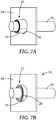
- An illustration of the wrapped pipe inserted into the plate is provided in Figure 7(a) . More specifically, Figure 7(a) illustrates an article 20 in which the polymeric structure 10 (i.e., tape) has been wrapped around the first substrate 22 (i.e., pipe) about four full circuits.
- the article 20 is disposed in an aperture 26 defined by a second substrate 24 (i.e., stainless steel plate).
- FIG. 7(b) provides a partial perspective view of an article 30, which includes the article 20 following subjection of the polymeric structure 10 (i.e., tape) to the elevated temperature from the heat gun, whereby the polymeric structure 10 has created at least a partial joint between the first substrate 22 and the second substrate 24.
- a heat gun Master Heat Gun, temperature range of 149°C - 260°C, obtained from Master Appliance, Racine, WI.
- the tape contracted in the cross-web (width) direction and reached a width of 1.3 cm, and the wrapped pipe reached a diameter of 2.6 cm.
- An illustration of the article following heating is provided in Figure 7(b).
- Figure 7(b) provides a partial perspective view of an article 30, which includes the article 20 following subjection of the polymeric structure 10 (i.e., tape) to the elevated temperature from the heat gun, whereby the polymeric structure 10 has created at least a partial joint between the first substrate 22 and the second substrate 24.
- the thickness of the polymeric structure 10 was increased and the width of the polymeric structure 10 was concomitantly decreased. In this embodiment, the thickness of the polymeric structure 10 increased to an extent that the outer diameter of the polymeric structure 10 was larger than the inner diameter of the aperture 26 in the second substrate 24.
- a piece of SF 1 film prepared to be a relaxed film as described in E1 was clamped and placed in a 130°C oven for 3 minutes. While hot, the clamped edges were separated by hand and held in the stretched state while the film cooled. The middle section of the film had increased in width by 300%.
- the cross-web-oriented film was then rinsed briefly with heptane and treated on one surface with a hand-held corona treater (Model BD-20AC, obtained from Electro-Technic Products, Inc. Chicago, IL) for two minutes. The same surface of the film was then wiped with TAPE PRIMER 94. After drying for two minutes, a film of PIB adhesive film prepared in PE1 was laminated to the primed surface.
- a hand-held corona treater Model BD-20AC, obtained from Electro-Technic Products, Inc. Chicago, IL
- a strip of laminated tape (3.8 cm wide and 19 cm long) was cut from the center of the larger piece of film with the shorter dimension of the film parallel to the direction of orientation of the film.
- the tape i.e., polymeric structure
- the tape was wrapped around a copper pipe (outside diameter of 1.6 cm) with approximately three full wraps, and the resulting wrapped pipe had an outside diameter of 1.9 cm.
- the surface of the tape with the PIB adhesive film was on the outside of the tape coil.
- the wrapped pipe was inserted into a 2.0 cm hole in a stainless steel plate (2.6 mm thick).
- the tape of the wrapped pipe was heated for 3 minutes using a heat gun.
- a piece of cross-web-oriented SF 1 film prepared as described in E2 above was wiped on one side with TAPE PRIMER 94.
- a film of VESTENAMER 8012 i.e., polycyclooctene, 0.15 mm thick
- a sample of this film was subjected to the shrinkage test with a result of 26% width and 112% length remaining after shrinking.
- a strip of tape (2.5 cm wide and 20 cm long) was cut from the center of the larger piece of film with the shorter dimension of the tape parallel to direction of orientation of the film.
- This tape i.e., polymeric structure
- This tape was wrapped around a copper pipe (outside diameter of 1.6 cm) with more than three full wraps.
- the surface of the tape with the polycyclooctene layer was on the outside of the tape coil.
- This wrapped pipe was inserted into a 2.0 cm hole in a stainless steel plate (2.6 mm thick).
- the tape of the wrapped pipe was heated for 1 minute and 30 second using a heat gun.
- a piece of ST 1 was split lengthwise.
- the convex side of this slit tube was pressed down onto a 130°C hot plate using a room temperature plate of aluminum, and it was pulled along the hot plate surface such that each point on the film's surface was in contact with the hot surface for approximately 5 seconds.
- the result was a flat film approximately 2.0 cm wide and 0.25 mm thick.
- Both faces of the film were wiped with TAPE PRIMER 94.
- the PIB adhesive film prepared in PE1 was then laminated to both of the primed faces of the film.
- the resulting film was cut to 1.9 cm wide and 27.7 cm long, and was 0.41 mm thick.
- the tape i.e., polymeric structure
- the tape was then wrapped around a copper pipe (outside diameter of 1.6 cm) with more than 4 full wraps.
- the wrapped pipe was inserted into a 2.0 cm hole in a stainless steel plate (2.6 mm thick).
- the tape of the wrapped pipe was heated for approximately 3 minutes using a heat gun.
- the resulting grommet-like seal was 1.1 cm wide, and the wrapped pipe was 2.4 cm in diameter.
- a piece of ST 2 with a 1.22 m (48 inches) length was split lengthwise.
- the convex side of this slit tube was passed over the surface of a 130°C hot plate several times to flatten the strip.
- the result was a flat film approximately 4.3 cm wide and 0.71 mm thick with a thermoplastic adhesive on one face.
- a sample of this film was subjected to the shrinkage test with a result of 43% width and 93% length remaining after shrinking.
- the tape (i.e., polymeric structure) prepared in PE 2 was modified by wiping the non-adhesive face with TAPE PRIMER 94.
- One liner from a strip of PIB adhesive film prepared in PE1 was then removed and the primed surface of the tape prepared above was laminated to the PIB adhesive film at room temperature.
- the excess margins of PIB adhesive film were trimmed away to produce a flat tape approximately 4.3 cm wide and 0.83 mm thick with a thermoplastic adhesive on one face and a pressure sensitive adhesive covered by a liner on the other face.
- a sample of this tape was subjected to the shrinkage test with a result of 43% width and 93% length remaining after shrinking.
- the tape i.e., polymeric structure prepared above in PE 3 was cut to 14 cm in length and wrapped around a piece of copper pipe (outside diameter of 1.6 cm, 15 cm long, capped with copper cap) to produce a coil of between two and three full wraps of tape with the thermoplastic adhesive on the inward face of the coil.
- the pressure sensitive adhesive prevented the coil from unwinding spontaneously.
- the copper pipe was centered within a 2.1 cm diameter opening in the middle of a sheet of galvanized steel (20 cm x 20 cm x 0.09 cm). The tape coil was slid along the pipe into the center of the opening in the galvanized sheet.
- the tape of the wrapped pipe was heated with a heat gun (Model HG-301A, obtained from Master Heat Gun, Racine, WI) set at 260°C for 3 minutes with heat applied uniformly to the wrapped pipe on both sides of the galvanized sheet.
- the coil shortened in width and increased in diameter to make a grommet-like seal and form an assembly, and the assembly was allowed to cool.
- the assembly was subjected to the leak test described above, and no water was observed to leak through the seal for more than two weeks.
- E6 was prepared in the same manner as E5, except with a modified heating method.
- a liquid propane torch was directly applied only to one side of the galvanized sheet and the copper pipe protruding from that side of the sheet. Heat was applied for 75 seconds, then the sample was allowed to rest for 60 seconds, then heat was applied for another 45 seconds.
- the tape i.e., polymeric structure
- a copper pipe identical to the one used in E5 was mounted within a 2.1 cm opening of a galvanized sheet identical to the one used in E5 using clamps with no seal between the pipe and the sheet. Upon subjecting this assembly to a leak test, the leak rate exceeded 100 mL per second, or 69 mL•s -1 •cm -2 .
- E7 was run using tapes (i.e., polymeric structures) prepared in PE 2 and tested in the same manner as in E5, except that the thermoplastic adhesive layer was on the outward face of the coil and there was no adhesive on the inward face of the coil. Upon leak testing, the leak rate was 4 mL per second, or 2.8 mL•s -1 •cm -2 .
- E8 was run using tapes (i.e., polymeric structures) prepared in PE 2 and tested in the same manner as E7 except that the thermoplastic adhesive layer was on the inward face of the coil and there was no adhesive on the outward face of the coil. To prevent the coil from unwinding spontaneously, the coil had to be gently squeezed by hand, and this pressure made it difficult to slide the coil along the pipe. Isopropanol was applied to the pipe surface to lubricate the interface between the pipe and the thermoplastic adhesive, and then the coil was easily slid along the pipe into the center of the opening in the galvanized sheet. After 5 minutes to let the isopropanol evaporate, the tape was heated as done in E5 and E7. Upon leak testing, the leak rate was 0.5 mL per second, or 0.3 mL•s -1 •cm -2 .
- a piece of the tape (i.e., polymeric structure) prepared in PE 3 was cut to 10 cm in length and wrapped around a piece of insulated electrical cable (10 gauge, 3 conductor, NM type, 15 cm long, average diameter of 0.98 cm, sealed on each end with a silicone grease) to produce a coil of between 2 and 2.5 full wraps of tape with the thermoplastic adhesive on the inward face of the coil.
- the pressure sensitive adhesive prevented the coil from unwinding spontaneously.
- the cable was centered within a 1.6 cm diameter opening in the middle of a sheet of acrylonitrile butadiene styrene (ABS) plastic (20 cm x 20 cm x 0.64 cm).
- ABS acrylonitrile butadiene styrene
- the tape of the wrapped cable was heated with a heat gun set at 150°C for 4 minutes with heat applied uniformly to both sides to form an assembly.
- the coil shortened in width and increased in diameter to make a grommet-like seal and form an assembly, and the assembly was allowed to cool.
- the leak rate was 1.2 mL/second, or 0.96 mL•s -1 •cm -2 .
- a piece of the tape (i.e., polymeric structure) prepared in PE 3 was used and tested in the same manner as E9 except that the tape was initially 13 cm long and the coil on the cable had between 2.5 and 3 full wraps. Upon testing, the leak rate was 0.2 mL/second, or 0.2 mL•s -1 •cm -2 .
- Pellets of DiARY MM9020 (6 grams) were placed on a piece of LINER L2 between two spacer strips each made from three layers of Polyester Tape 8403. An additional piece of LINER L2 was placed on top of the urethane. This stack was placed in a hydraulic press at 176°C (350°F) and heated with no pressure for two minutes. Then, 130 kiloNewtons (kN) of compression force was applied for five minutes. The resulting polyurethane film was 0.18 mm thick. This film was placed in a 115°C oven for 20 minutes and then stretched by hand uniaxially in the width direction to 50% elongation to produce a film 0.10 mm thick.
- kN kiloNewtons
- a cylindrical piece of HOT MELT 3792 (1.5 cm diameter x 1.9 cm long) was placed on the urethane film between pieces of LINER L2 and pressed in a hydraulic press at 164°F (73°C) for 90 seconds with 130 kN of compression force.
- the resulting laminate was 0.23 mm thick.
- An acrylic PSA 467MP tape was laminated of the other face of the urethane film. A sample of this film was subjected to the shrinkage test with a result of 64% width and 113% length.
- a piece of SF 2 shrink film (210 cm x 25 cm x 0.03 mm) was heated with a heat gun to relax it and remove its orientation. It was then oriented in the width direction using the same method used in E1 to produce a film 0.05 mm thick.
- HOT MELT 3792 was placed on a piece of this film (17 cm x 10 cm), and sheets of LINER L2 were placed on both sides. This stack was pressed at 73°C (164°F) with 80 kN of applied compression force for three minutes. The resulting film was a laminate of the shrink film and hot melt adhesive with a thickness of 0.15 mm.
- the remaining face of the shrink film was wiped with TAPE PRIMER 94, and then one layer of PIB adhesive film prepared in PE1 was laminated to the shrink film.
- the resulting film was a laminate of hot melt adhesive, shrink film, and pressure sensitive adhesive with a total thickness of 0.25 mm.
- a sample of this laminate film was subjected to the shrinkage test with a result of 47% width and 117% length remaining after shrinking.
- Another piece of this film was cut to 4.5 cm long and 2.5 cm wide and wrapped around a stainless steel tube (15 cm long, 0.64 cm outside diameter) to make a tape coil with 4.5 full wraps and an outside diameter of 0.86 cm.
- the compliance of the tape made it easier to wrap compared to E12, and it did not tend to elastically unwind if pressure was removed from the coil.
- This tape coil was slid along the tube into an opening (0.89 cm diameter) within a galvanized steel sheet (20 cm x 20 cm x 0.09 cm).
- the tape of the wrapped tube was heated with a heat gun set at 260°C for 120 seconds to form an assembly.
- the tape coil shrank in width to 1.4 cm and the wrapped tube increased in outer diameter to an average of 1.1 cm.
- the leak rate was 0.0005 mL/s, or 0.002 mL•s -1 •cm -2 .
- a piece of ST 2 was split lengthwise and partially relaxed to form a tape (i.e., polymeric structure) approximately 2.0 cm wide and 0.25 mm thick as described in E4.
- a piece of this tape (6.4 cm x 1.9 cm x 0.25 mm) was wrapped around a stainless steel tube (17 cm long, 0.64 cm outside diameter) with 2.75 full wraps and an outside diameter of 0.76 cm.
- the compliance of the tape made it easy to wrap and tended not to elastically unwind if pressure was removed from the coil.
- This tape coil was inserted into an opening (0.79 cm diameter) within a galvanized steel sheet (20 cm x 20 cm x 0.09 cm).
- the tape of the wrapped tube was heated with a heat gun set at 260°C for 90 seconds to form an assembly.
- the tape coil shrank in width to 1.0 cm and the wrapped tube increased in outer diameter to an average of 0.94 cm.
- the leak rate was 0.08 mL/s, or 0.5 mL•s -1 •cm -2 .
- the tape (i.e., polymeric structure) from E13 was placed on piece of liner L2 in a 120°C oven for five minutes to relax substantially all of the tape's orientation.
- the resulting tape was approximately 0.8 cm wide and 0.67 mm thick.
- a piece of this tape (2.2 cm long) was wrapped around a stainless steel tube (17 cm long, 0.64 cm outside diameter) with 1.0 full wraps and an outside diameter of 0.76 cm.
- This tape coil was inserted into an opening (0.79 cm diameter) within a galvanized steel sheet (20 cm x 20 cm x 0.09 cm).
- the tape of the wrapped tube was heated with a heat gun set at 260°C for 90 seconds to form an assembly.
- the tape coil retained its original dimension of 0.76 cm in diameter and the wrapped tube 0.8 cm in width.
- the assembly was subjected to leak testing, but the method had to be modified by supporting the tube with a clamp because the tape alone did not provide enough support to hold the tube within the opening.
- the leak rate was 13 mL/s, or 77 mL•s -1 •cm -2 .
Claims (15)
- Ein Verfahren, umfassend:a. Bereitstellen einer Polymerstruktur, umfassend eine Länge, eine Breite und eine Dicke, wobei die Länge der Polymerstruktur größer als die Breite der Polymerstruktur ist, wobei die Polymerstruktur eine vernetzte Polymerschicht umfasst, die in der Breitenrichtung mit einem Reckverhältnis von mindestens 1,2:1 einachsig ausgerichtet ist;b. Wickeln der Polymerstruktur um ein erstes Substrat mit mindestens zwei vollständigen Windungen;c. Positionieren der Polymerstruktur zumindest teilweise in einer Öffnung, die durch ein zweites Substrat definiert ist; undd. Aussetzen der Polymerstruktur einer Temperatur oberhalb der Glasübergangstemperatur der vernetzten Polymerschicht und unterhalb der Qualitätsverlusttemperatur der vernetzten Polymerschicht und beliebiger anderer in der Polymerstruktur vorliegender Bestandteile, wodurch die Dicke der Polymerstruktur erhöht und zumindest eine Teilverbindung zwischen dem ersten Substrat und dem zweiten Substrat erzeugt wird.
- Das Verfahren nach Anspruch 1, wobei die Polymerstruktur ferner eine erste Haftschicht benachbart zu einer ersten Hauptoberfläche der vernetzten Polymerschicht umfasst.
- Das Verfahren nach Anspruch 1 oder Anspruch 2, wobei die Polymerstruktur ferner eine zweite Haftschicht benachbart zu einer zweiten Hauptfläche der vernetzten Polymerschicht umfasst.
- Das Verfahren nach Anspruch 2, wobei die erste Haftschicht einen Heißschmelzkleber umfasst.
- Das Verfahren nach Anspruch 3, wobei die zweite Haftschicht einen Haftkleber umfasst.
- Das Verfahren nach einem der Ansprüche 1 bis 5, wobei das Positionieren das Schieben der Polymerstruktur über eine Strecke von mindestens einem Viertel der Breite der Polymerstruktur in die durch das zweite Substrat definierte Öffnung umfasst.
- Das Verfahren nach einem der Ansprüche 1 bis 6, wobei die Breite der Polymerstruktur um zwischen 10 % und 80 % abnimmt, wenn sie der erhöhten Temperatur ausgesetzt wird.
- Das Verfahren nach einem der Ansprüche 1 bis 7, wobei die Polymerstruktur in Kontakt mit dem zweiten Substrat steht, sodass Wasser, das bei einem Druck von 6000 Pascal (Pa) auf die Verbindung zwischen dem ersten Substrat und dem zweiten Substrat aufgebracht wird, zwischen der Polymerstruktur und dem zweiten Substrat mit einer Geschwindigkeit von 4 Millilitern pro Sekunde (ml/s) oder weniger oder 3 Millilitern pro Sekunde pro Quadratzentimeter (ml s-1 cm-2) oder weniger hindurchläuft.
- Das Verfahren nach einem der Ansprüche 1 bis 8, wobei das erste Substrat ein Rohr, ein Kabel, einen Schlauch, eine Stange, einen Draht oder ein Bündel aus einer oder mehreren Kombinationen davon umfasst.
- Verfahren nach einem der Ansprüche 1 bis 9, wobei das erste Substrat kein zugängliches Ende umfasst.
- Ein Artikel, umfassend ein Substrat und eine Polymerstruktur, die um mindestens zwei volle Windungen um das Substrat gewickelt ist, wobei die Polymerstruktur eine Länge, eine Breite und eine Dicke aufweist und eine vernetzte Polymerschicht umfasst, die in der Breitenrichtung mit einem Reckverhältnis von mindestens 1,2:1 einachsig ausgerichtet ist, wobei die Länge der Polymerstruktur größer als die Breite der Polymerstruktur ist.
- Der Artikel nach Anspruch 11, wobei die Polymerstruktur ferner eine erste Haftschicht benachbart zu einer ersten Hauptoberfläche der vernetzten Polymerschicht umfasst.
- Der Artikel nach Anspruch 12, wobei die Polymerstruktur ferner eine zweite Haftschicht benachbart zu einer zweiten Hauptfläche der vernetzten Polymerschicht umfasst.
- Der Artikel nach einem der Ansprüche 11 bis 13, wobei die vernetzte Polymerschicht in der Breitenrichtung mit einem Reckverhältnis von 1,2:1 bis 4:1 ausgerichtet ist.
- Der Artikel nach einem der Ansprüche 11 bis 14, wobei das Substrat ein Rohr, ein Kabel, einen Schlauch, eine Stange, einen Draht oder ein Bündel aus einer oder mehreren Kombinationen davon einschließt.
Applications Claiming Priority (2)
| Application Number | Priority Date | Filing Date | Title |
|---|---|---|---|
| US201361831844P | 2013-06-06 | 2013-06-06 | |
| PCT/US2014/040703 WO2014197476A1 (en) | 2013-06-06 | 2014-06-03 | Articles and methods of wrapping a substrate with a polymeric structure |
Publications (2)
| Publication Number | Publication Date |
|---|---|
| EP3003717A1 EP3003717A1 (de) | 2016-04-13 |
| EP3003717B1 true EP3003717B1 (de) | 2020-02-19 |
Family
ID=50983244
Family Applications (1)
| Application Number | Title | Priority Date | Filing Date |
|---|---|---|---|
| EP14732810.8A Active EP3003717B1 (de) | 2013-06-06 | 2014-06-03 | Artikel und verfahren zum einwickeln eines substrats mit einer polymerstruktur |
Country Status (6)
| Country | Link |
|---|---|
| US (1) | US10030791B2 (de) |
| EP (1) | EP3003717B1 (de) |
| JP (1) | JP6341995B2 (de) |
| KR (1) | KR101855218B1 (de) |
| CN (1) | CN105307855B (de) |
| WO (1) | WO2014197476A1 (de) |
Families Citing this family (9)
| Publication number | Priority date | Publication date | Assignee | Title |
|---|---|---|---|---|
| WO2015037426A1 (ja) * | 2013-09-10 | 2015-03-19 | 旭化成ケミカルズ株式会社 | 離型フィルム、成型体の製造方法、半導体部品及びリフレクター部品 |
| SE538128C2 (sv) * | 2014-10-07 | 2016-03-08 | Mct Brattberg Ab | Insert block half |
| US10518931B2 (en) * | 2017-05-11 | 2019-12-31 | Lesweek Pty Ltd | Load bearing structure |
| CA2973567A1 (en) * | 2017-07-17 | 2019-01-17 | Gabe Coscarella | Weather barrier for a building penetration with a removable collar |
| DE102017125205A1 (de) | 2017-10-27 | 2019-05-02 | R. Stahl Schaltgeräte GmbH | Verfahren zur Herstellung einer explosionsgeschützten Leitungsdurchführung und explosionsgeschützte Leitungsdurchführung |
| US10822815B1 (en) * | 2019-03-19 | 2020-11-03 | Paul Vance | Circular perforated drywall tape |
| US20200392380A1 (en) * | 2019-06-13 | 2020-12-17 | Microsoft Technology Licensing, Llc | Double-sided adhesive tape |
| EP3789312A1 (de) * | 2019-09-04 | 2021-03-10 | Brady Corporation Limited | Aufprallschutz und verfahren zur herstellung |
| DE102022102979A1 (de) | 2022-02-09 | 2023-08-10 | Tesa Se | Verfahren zur Anordnung strangförmiger Elemente in durchgehenden Ausnehmungen und Klebeelement für das Verfahren |
Family Cites Families (26)
| Publication number | Priority date | Publication date | Assignee | Title |
|---|---|---|---|---|
| US1284569A (en) | 1917-12-15 | 1918-11-12 | Waclaw Bikowski | Portable farm-fence. |
| GB1392212A (en) | 1971-04-02 | 1975-04-30 | Raychem Corp | Involutely heat-recoverable articles |
| GB1437177A (en) | 1972-08-21 | 1976-05-26 | Raychem Corp | Feed through connections |
| US4035534A (en) | 1972-09-01 | 1977-07-12 | Raychem Corporation | Heat-shrinkable laminate |
| GB1604444A (en) | 1977-09-30 | 1981-12-09 | Raychem Ltd | Heatrecoverable articles |
| US4348438A (en) | 1980-12-31 | 1982-09-07 | Mobil Oil Corporation | Process for preparation of improved shrink wrap |
| US4624720A (en) | 1983-01-06 | 1986-11-25 | Raychem Ltd | Dimensionally heat-recoverable article |
| US4762748A (en) * | 1986-06-30 | 1988-08-09 | W. R. Grace & Co. | Multilayer film with better layer adhesion |
| DE3631698A1 (de) | 1986-08-16 | 1988-03-24 | Kabelmetal Electro Gmbh | Verfahren zur herstellung eines bandes aus einem bei waermezufuhr schrumpfbaren kunststoff |
| US4961797A (en) | 1987-01-14 | 1990-10-09 | The Kendall Company | Method for protecting a tubular metal article |
| GB8708135D0 (en) | 1987-04-06 | 1987-05-13 | Raychem Sa Nv | Sealing device |
| DE3853565T2 (de) | 1987-09-09 | 1996-01-18 | Raychem As | Wärmerückstellbarer Artikel. |
| EP0328367A3 (de) | 1988-02-08 | 1991-06-26 | N.V. Raychem S.A. | Durchgangsdichtung |
| IL89671A0 (en) | 1988-03-29 | 1989-09-28 | Raychem Corp | Heat-recoverable article and method for enclosing and sealing a substrate |
| US5134000A (en) * | 1989-08-10 | 1992-07-28 | Shaw Industries Ltd. | Heat shrinkable protective sheets and methods for their manufacture |
| JP2951981B2 (ja) * | 1989-11-30 | 1999-09-20 | 大阪瓦斯株式会社 | 被覆用シート |
| US5302428A (en) * | 1992-09-29 | 1994-04-12 | Shaw Industries Ltd. | Multi-layer wraparound heat shrink sleeve |
| JPH0996380A (ja) * | 1995-09-29 | 1997-04-08 | Sekisui Chem Co Ltd | 配管材 |
| JP4287384B2 (ja) * | 1998-04-17 | 2009-07-01 | 未来工業株式会社 | 貫通部閉鎖具 |
| JP4633983B2 (ja) | 1999-06-18 | 2011-02-16 | スリーエム イノベイティブ プロパティズ カンパニー | 湿潤粘着性感圧接着剤 |
| DE10036407A1 (de) * | 2000-07-26 | 2002-02-07 | Mitsubishi Polyester Film Gmbh | Mehrschichtige, transparente, biaxial orientierte Polyesterfolie |
| US20040028862A1 (en) * | 2002-08-12 | 2004-02-12 | Burwell Douglas Neil | Fibrous closure for heat-shrinkable covers |
| JP4533006B2 (ja) * | 2004-06-08 | 2010-08-25 | 積水化学工業株式会社 | 防火区画貫通部構造、及び防火区画貫通部の施工方法 |
| JP2007154566A (ja) | 2005-12-07 | 2007-06-21 | Sekisui Chem Co Ltd | 防火区画貫通部構造 |
| GB0800765D0 (en) | 2008-01-16 | 2008-02-27 | Beele Eng Bv | Fire-stop system for placement in a conduit through which a thermally weakenable pipe extends, method for placing the system and conduit provided |
| CN102676073A (zh) * | 2011-03-18 | 2012-09-19 | 中国石油天然气集团公司 | 一种管道补口热烤压敏带的生产方法 |
-
2014
- 2014-06-03 US US14/783,592 patent/US10030791B2/en not_active Expired - Fee Related
- 2014-06-03 JP JP2016518411A patent/JP6341995B2/ja not_active Expired - Fee Related
- 2014-06-03 KR KR1020167000065A patent/KR101855218B1/ko active IP Right Grant
- 2014-06-03 CN CN201480032155.1A patent/CN105307855B/zh not_active Expired - Fee Related
- 2014-06-03 WO PCT/US2014/040703 patent/WO2014197476A1/en active Application Filing
- 2014-06-03 EP EP14732810.8A patent/EP3003717B1/de active Active
Non-Patent Citations (1)
| Title |
|---|
| None * |
Also Published As
| Publication number | Publication date |
|---|---|
| WO2014197476A1 (en) | 2014-12-11 |
| US10030791B2 (en) | 2018-07-24 |
| KR20160014761A (ko) | 2016-02-11 |
| CN105307855A (zh) | 2016-02-03 |
| KR101855218B1 (ko) | 2018-05-08 |
| EP3003717A1 (de) | 2016-04-13 |
| JP6341995B2 (ja) | 2018-06-13 |
| JP2016532829A (ja) | 2016-10-20 |
| CN105307855B (zh) | 2017-06-13 |
| US20160076673A1 (en) | 2016-03-17 |
Similar Documents
| Publication | Publication Date | Title |
|---|---|---|
| EP3003717B1 (de) | Artikel und verfahren zum einwickeln eines substrats mit einer polymerstruktur | |
| JP4545926B2 (ja) | 感圧接着剤を成形ゴム製品に結合する方法 | |
| US5901962A (en) | Environmental sealing | |
| JP5506298B2 (ja) | エレクトレット化フィルム | |
| WO2010033276A3 (en) | Multilayer films having improved sealing properties, their methods of manufacture, and articles made therefrom | |
| JP3908876B2 (ja) | 粘着テープ用基材フィルム及び粘着テープまたはシート | |
| JPH07268291A (ja) | 芯まで透明な外観を有する感圧接着剤テープロールの製造法 | |
| EP1058708A2 (de) | Heisssiegelfähige kunststoffverbundfilme | |
| JP5628132B2 (ja) | 易滑及び離型性熱可塑性樹脂フィルム並びに該熱可塑性樹脂フィルムからなる包装体及び離型又は加工プロセス用支持体フィルム | |
| KR101735364B1 (ko) | 강관용 폴리에틸렌 코팅필름 조성물과 그를 이용한 코팅필름 및 그 제조방법 | |
| KR20160019484A (ko) | 구조 접착제를 포함하는 접착제 층을 갖는 접착 테이프 롤 및 그의 제조 방법 | |
| US4925715A (en) | Linerless roll of self fusing tape | |
| CN1436125A (zh) | 层压材料及其用途 | |
| JP2011016859A (ja) | シート状粘着組成物、及びそれを有する粘着シート | |
| ES2881180T3 (es) | Material adhesivo multicapa para utilización alimenticia | |
| WO2006081640A1 (en) | A bi-oriented polypropylene film comprising tear orientation, a process of preparing said film and an article comprising it | |
| FI107243B (fi) | Lämpösaumattava monikerroskalvo, menetelmä sen valmistamiseksi ja pakkaus | |
| JP5041879B2 (ja) | ポリアミドフィルムおよびその製造方法 | |
| WO2007015245A2 (en) | Thermoplastic shrinkable polymeric film | |
| JP2004083706A (ja) | 離型用粘着テープおよびエンドレスベルト | |
| JP2001138422A (ja) | 発泡シート及びその製造方法 | |
| JPH0376656B2 (de) | ||
| EP1646490A1 (de) | Polymerschaumröhre für rohrisolierungen und verfahren zur kontinuierlichen herstellung solch einer röhre | |
| FR2812652A1 (fr) | Bandes adhesives empilables sans protecteur | |
| JP2011016860A (ja) | シート状粘着組成物、及びそれを有する粘着シート |
Legal Events
| Date | Code | Title | Description |
|---|---|---|---|
| PUAI | Public reference made under article 153(3) epc to a published international application that has entered the european phase |
Free format text: ORIGINAL CODE: 0009012 |
|
| 17P | Request for examination filed |
Effective date: 20151126 |
|
| AK | Designated contracting states |
Kind code of ref document: A1 Designated state(s): AL AT BE BG CH CY CZ DE DK EE ES FI FR GB GR HR HU IE IS IT LI LT LU LV MC MK MT NL NO PL PT RO RS SE SI SK SM TR |
|
| AX | Request for extension of the european patent |
Extension state: BA ME |
|
| DAX | Request for extension of the european patent (deleted) | ||
| STAA | Information on the status of an ep patent application or granted ep patent |
Free format text: STATUS: EXAMINATION IS IN PROGRESS |
|
| 17Q | First examination report despatched |
Effective date: 20190205 |
|
| GRAP | Despatch of communication of intention to grant a patent |
Free format text: ORIGINAL CODE: EPIDOSNIGR1 |
|
| STAA | Information on the status of an ep patent application or granted ep patent |
Free format text: STATUS: GRANT OF PATENT IS INTENDED |
|
| INTG | Intention to grant announced |
Effective date: 20190912 |
|
| GRAS | Grant fee paid |
Free format text: ORIGINAL CODE: EPIDOSNIGR3 |
|
| GRAA | (expected) grant |
Free format text: ORIGINAL CODE: 0009210 |
|
| STAA | Information on the status of an ep patent application or granted ep patent |
Free format text: STATUS: THE PATENT HAS BEEN GRANTED |
|
| AK | Designated contracting states |
Kind code of ref document: B1 Designated state(s): AL AT BE BG CH CY CZ DE DK EE ES FI FR GB GR HR HU IE IS IT LI LT LU LV MC MK MT NL NO PL PT RO RS SE SI SK SM TR |
|
| REG | Reference to a national code |
Ref country code: CH Ref legal event code: EP |
|
| REG | Reference to a national code |
Ref country code: DE Ref legal event code: R096 Ref document number: 602014061202 Country of ref document: DE |
|
| REG | Reference to a national code |
Ref country code: AT Ref legal event code: REF Ref document number: 1234477 Country of ref document: AT Kind code of ref document: T Effective date: 20200315 |
|
| REG | Reference to a national code |
Ref country code: IE Ref legal event code: FG4D |
|
| REG | Reference to a national code |
Ref country code: NL Ref legal event code: MP Effective date: 20200219 |
|
| PG25 | Lapsed in a contracting state [announced via postgrant information from national office to epo] |
Ref country code: NO Free format text: LAPSE BECAUSE OF FAILURE TO SUBMIT A TRANSLATION OF THE DESCRIPTION OR TO PAY THE FEE WITHIN THE PRESCRIBED TIME-LIMIT Effective date: 20200519 Ref country code: FI Free format text: LAPSE BECAUSE OF FAILURE TO SUBMIT A TRANSLATION OF THE DESCRIPTION OR TO PAY THE FEE WITHIN THE PRESCRIBED TIME-LIMIT Effective date: 20200219 Ref country code: RS Free format text: LAPSE BECAUSE OF FAILURE TO SUBMIT A TRANSLATION OF THE DESCRIPTION OR TO PAY THE FEE WITHIN THE PRESCRIBED TIME-LIMIT Effective date: 20200219 |
|
| REG | Reference to a national code |
Ref country code: LT Ref legal event code: MG4D |
|
| PG25 | Lapsed in a contracting state [announced via postgrant information from national office to epo] |
Ref country code: IS Free format text: LAPSE BECAUSE OF FAILURE TO SUBMIT A TRANSLATION OF THE DESCRIPTION OR TO PAY THE FEE WITHIN THE PRESCRIBED TIME-LIMIT Effective date: 20200619 Ref country code: SE Free format text: LAPSE BECAUSE OF FAILURE TO SUBMIT A TRANSLATION OF THE DESCRIPTION OR TO PAY THE FEE WITHIN THE PRESCRIBED TIME-LIMIT Effective date: 20200219 Ref country code: HR Free format text: LAPSE BECAUSE OF FAILURE TO SUBMIT A TRANSLATION OF THE DESCRIPTION OR TO PAY THE FEE WITHIN THE PRESCRIBED TIME-LIMIT Effective date: 20200219 Ref country code: LV Free format text: LAPSE BECAUSE OF FAILURE TO SUBMIT A TRANSLATION OF THE DESCRIPTION OR TO PAY THE FEE WITHIN THE PRESCRIBED TIME-LIMIT Effective date: 20200219 Ref country code: GR Free format text: LAPSE BECAUSE OF FAILURE TO SUBMIT A TRANSLATION OF THE DESCRIPTION OR TO PAY THE FEE WITHIN THE PRESCRIBED TIME-LIMIT Effective date: 20200520 Ref country code: BG Free format text: LAPSE BECAUSE OF FAILURE TO SUBMIT A TRANSLATION OF THE DESCRIPTION OR TO PAY THE FEE WITHIN THE PRESCRIBED TIME-LIMIT Effective date: 20200519 |
|
| PG25 | Lapsed in a contracting state [announced via postgrant information from national office to epo] |
Ref country code: NL Free format text: LAPSE BECAUSE OF FAILURE TO SUBMIT A TRANSLATION OF THE DESCRIPTION OR TO PAY THE FEE WITHIN THE PRESCRIBED TIME-LIMIT Effective date: 20200219 |
|
| PG25 | Lapsed in a contracting state [announced via postgrant information from national office to epo] |
Ref country code: ES Free format text: LAPSE BECAUSE OF FAILURE TO SUBMIT A TRANSLATION OF THE DESCRIPTION OR TO PAY THE FEE WITHIN THE PRESCRIBED TIME-LIMIT Effective date: 20200219 Ref country code: DK Free format text: LAPSE BECAUSE OF FAILURE TO SUBMIT A TRANSLATION OF THE DESCRIPTION OR TO PAY THE FEE WITHIN THE PRESCRIBED TIME-LIMIT Effective date: 20200219 Ref country code: SM Free format text: LAPSE BECAUSE OF FAILURE TO SUBMIT A TRANSLATION OF THE DESCRIPTION OR TO PAY THE FEE WITHIN THE PRESCRIBED TIME-LIMIT Effective date: 20200219 Ref country code: LT Free format text: LAPSE BECAUSE OF FAILURE TO SUBMIT A TRANSLATION OF THE DESCRIPTION OR TO PAY THE FEE WITHIN THE PRESCRIBED TIME-LIMIT Effective date: 20200219 Ref country code: EE Free format text: LAPSE BECAUSE OF FAILURE TO SUBMIT A TRANSLATION OF THE DESCRIPTION OR TO PAY THE FEE WITHIN THE PRESCRIBED TIME-LIMIT Effective date: 20200219 Ref country code: RO Free format text: LAPSE BECAUSE OF FAILURE TO SUBMIT A TRANSLATION OF THE DESCRIPTION OR TO PAY THE FEE WITHIN THE PRESCRIBED TIME-LIMIT Effective date: 20200219 Ref country code: PT Free format text: LAPSE BECAUSE OF FAILURE TO SUBMIT A TRANSLATION OF THE DESCRIPTION OR TO PAY THE FEE WITHIN THE PRESCRIBED TIME-LIMIT Effective date: 20200712 Ref country code: CZ Free format text: LAPSE BECAUSE OF FAILURE TO SUBMIT A TRANSLATION OF THE DESCRIPTION OR TO PAY THE FEE WITHIN THE PRESCRIBED TIME-LIMIT Effective date: 20200219 Ref country code: SK Free format text: LAPSE BECAUSE OF FAILURE TO SUBMIT A TRANSLATION OF THE DESCRIPTION OR TO PAY THE FEE WITHIN THE PRESCRIBED TIME-LIMIT Effective date: 20200219 |
|
| REG | Reference to a national code |
Ref country code: AT Ref legal event code: MK05 Ref document number: 1234477 Country of ref document: AT Kind code of ref document: T Effective date: 20200219 |
|
| REG | Reference to a national code |
Ref country code: DE Ref legal event code: R097 Ref document number: 602014061202 Country of ref document: DE |
|
| PLBE | No opposition filed within time limit |
Free format text: ORIGINAL CODE: 0009261 |
|
| STAA | Information on the status of an ep patent application or granted ep patent |
Free format text: STATUS: NO OPPOSITION FILED WITHIN TIME LIMIT |
|
| 26N | No opposition filed |
Effective date: 20201120 |
|
| PG25 | Lapsed in a contracting state [announced via postgrant information from national office to epo] |
Ref country code: IT Free format text: LAPSE BECAUSE OF FAILURE TO SUBMIT A TRANSLATION OF THE DESCRIPTION OR TO PAY THE FEE WITHIN THE PRESCRIBED TIME-LIMIT Effective date: 20200219 Ref country code: AT Free format text: LAPSE BECAUSE OF FAILURE TO SUBMIT A TRANSLATION OF THE DESCRIPTION OR TO PAY THE FEE WITHIN THE PRESCRIBED TIME-LIMIT Effective date: 20200219 Ref country code: MC Free format text: LAPSE BECAUSE OF FAILURE TO SUBMIT A TRANSLATION OF THE DESCRIPTION OR TO PAY THE FEE WITHIN THE PRESCRIBED TIME-LIMIT Effective date: 20200219 |
|
| REG | Reference to a national code |
Ref country code: CH Ref legal event code: PL |
|
| PG25 | Lapsed in a contracting state [announced via postgrant information from national office to epo] |
Ref country code: PL Free format text: LAPSE BECAUSE OF FAILURE TO SUBMIT A TRANSLATION OF THE DESCRIPTION OR TO PAY THE FEE WITHIN THE PRESCRIBED TIME-LIMIT Effective date: 20200219 Ref country code: SI Free format text: LAPSE BECAUSE OF FAILURE TO SUBMIT A TRANSLATION OF THE DESCRIPTION OR TO PAY THE FEE WITHIN THE PRESCRIBED TIME-LIMIT Effective date: 20200219 |
|
| GBPC | Gb: european patent ceased through non-payment of renewal fee |
Effective date: 20200603 |
|
| PG25 | Lapsed in a contracting state [announced via postgrant information from national office to epo] |
Ref country code: LU Free format text: LAPSE BECAUSE OF NON-PAYMENT OF DUE FEES Effective date: 20200603 |
|
| REG | Reference to a national code |
Ref country code: BE Ref legal event code: MM Effective date: 20200630 |
|
| PG25 | Lapsed in a contracting state [announced via postgrant information from national office to epo] |
Ref country code: FR Free format text: LAPSE BECAUSE OF NON-PAYMENT OF DUE FEES Effective date: 20200630 Ref country code: CH Free format text: LAPSE BECAUSE OF NON-PAYMENT OF DUE FEES Effective date: 20200630 Ref country code: LI Free format text: LAPSE BECAUSE OF NON-PAYMENT OF DUE FEES Effective date: 20200630 Ref country code: GB Free format text: LAPSE BECAUSE OF NON-PAYMENT OF DUE FEES Effective date: 20200603 Ref country code: IE Free format text: LAPSE BECAUSE OF NON-PAYMENT OF DUE FEES Effective date: 20200603 |
|
| PG25 | Lapsed in a contracting state [announced via postgrant information from national office to epo] |
Ref country code: BE Free format text: LAPSE BECAUSE OF NON-PAYMENT OF DUE FEES Effective date: 20200630 |
|
| PGFP | Annual fee paid to national office [announced via postgrant information from national office to epo] |
Ref country code: DE Payment date: 20210505 Year of fee payment: 8 |
|
| PG25 | Lapsed in a contracting state [announced via postgrant information from national office to epo] |
Ref country code: TR Free format text: LAPSE BECAUSE OF FAILURE TO SUBMIT A TRANSLATION OF THE DESCRIPTION OR TO PAY THE FEE WITHIN THE PRESCRIBED TIME-LIMIT Effective date: 20200219 Ref country code: MT Free format text: LAPSE BECAUSE OF FAILURE TO SUBMIT A TRANSLATION OF THE DESCRIPTION OR TO PAY THE FEE WITHIN THE PRESCRIBED TIME-LIMIT Effective date: 20200219 Ref country code: CY Free format text: LAPSE BECAUSE OF FAILURE TO SUBMIT A TRANSLATION OF THE DESCRIPTION OR TO PAY THE FEE WITHIN THE PRESCRIBED TIME-LIMIT Effective date: 20200219 |
|
| PG25 | Lapsed in a contracting state [announced via postgrant information from national office to epo] |
Ref country code: MK Free format text: LAPSE BECAUSE OF FAILURE TO SUBMIT A TRANSLATION OF THE DESCRIPTION OR TO PAY THE FEE WITHIN THE PRESCRIBED TIME-LIMIT Effective date: 20200219 Ref country code: AL Free format text: LAPSE BECAUSE OF FAILURE TO SUBMIT A TRANSLATION OF THE DESCRIPTION OR TO PAY THE FEE WITHIN THE PRESCRIBED TIME-LIMIT Effective date: 20200219 |
|
| REG | Reference to a national code |
Ref country code: DE Ref legal event code: R119 Ref document number: 602014061202 Country of ref document: DE |
|
| PG25 | Lapsed in a contracting state [announced via postgrant information from national office to epo] |
Ref country code: DE Free format text: LAPSE BECAUSE OF NON-PAYMENT OF DUE FEES Effective date: 20230103 |