EP2996979B1 - Systeme de prehension securise - Google Patents
Systeme de prehension securise Download PDFInfo
- Publication number
- EP2996979B1 EP2996979B1 EP14731687.1A EP14731687A EP2996979B1 EP 2996979 B1 EP2996979 B1 EP 2996979B1 EP 14731687 A EP14731687 A EP 14731687A EP 2996979 B1 EP2996979 B1 EP 2996979B1
- Authority
- EP
- European Patent Office
- Prior art keywords
- lifting beam
- arms
- beams
- guiding area
- closed position
- Prior art date
- Legal status (The legal status is an assumption and is not a legal conclusion. Google has not performed a legal analysis and makes no representation as to the accuracy of the status listed.)
- Active
Links
Images

Classifications
-
- B—PERFORMING OPERATIONS; TRANSPORTING
- B66—HOISTING; LIFTING; HAULING
- B66C—CRANES; LOAD-ENGAGING ELEMENTS OR DEVICES FOR CRANES, CAPSTANS, WINCHES, OR TACKLES
- B66C1/00—Load-engaging elements or devices attached to lifting or lowering gear of cranes or adapted for connection therewith for transmitting lifting forces to articles or groups of articles
- B66C1/10—Load-engaging elements or devices attached to lifting or lowering gear of cranes or adapted for connection therewith for transmitting lifting forces to articles or groups of articles by mechanical means
- B66C1/42—Gripping members engaging only the external or internal surfaces of the articles
- B66C1/422—Gripping members engaging only the external or internal surfaces of the articles actuated by lifting force
-
- B—PERFORMING OPERATIONS; TRANSPORTING
- B66—HOISTING; LIFTING; HAULING
- B66C—CRANES; LOAD-ENGAGING ELEMENTS OR DEVICES FOR CRANES, CAPSTANS, WINCHES, OR TACKLES
- B66C1/00—Load-engaging elements or devices attached to lifting or lowering gear of cranes or adapted for connection therewith for transmitting lifting forces to articles or groups of articles
- B66C1/10—Load-engaging elements or devices attached to lifting or lowering gear of cranes or adapted for connection therewith for transmitting lifting forces to articles or groups of articles by mechanical means
Definitions
- the invention lies in the field of lifting, more particularly in the gripping systems used by lifting beams.
- the lifting beams are intended to carry bulky and heavy loads. They must ensure the safety of the load and the operators. However, current safeguards are generally active, that is to say they require the active participation of an operator and this security is therefore subject to a risk of human error.
- EP0857685A2 , US6322120B1 , US5979961A , DE2054032A1 and JPS5412964A disclose spreaders comprising gripping systems with two arms.
- the aim of the invention is to provide a lifting beam suitable for solving all or part of the problems mentioned above, in particular to ensure maximum passive safety.
- a lifter according to the invention is defined in claim 1.
- Optional characteristics are defined in claims 2 to 12.
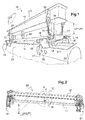
- the figure 1 illustrates a first lifter 10 not in accordance with the invention.
- the lifter 10 is substantially symmetrical with respect to a vertical longitudinal plane P10; it is also symmetrical relatively to a transverse vertical plane, perpendicular to the longitudinal plane of symmetry P10.
- the spreader 10 comprises a lower beam 11 and an upper beam 12.
- the beams 11, 12 are box beams; they extend longitudinally substantially over the entire length of the lifter, one 12 above the other 11; they are substantially parallel to each other.
- Each end 13 of the lower beam 11 carries a transverse beam 14 comprising two cheeks 15 in the form of plates, longitudinally separated from each other by an interval 16.
- a gripping system 17 is articulated in rotation around a longitudinal axis X17, at each end 18 of the joist 14.
- the lifter 10 is handled by lifting means shown schematically in the figures by an arrow V; these lifting means can be a crane or a traveling crane, they are fixed to the upper beam 12 by a hook and / or lifting slings.
- the gripping system 17 comprises a proximal part, relative to the longitudinal plane of symmetry P10, forming a counterweight 21, and a distal part forming a hook 22.
- the lifter 10 is used for lifting a tank 23.
- the tank 23 is equipped with vertical reinforcing plates 24 in which openings 25 are formed.
- Each hook 22 is provided to engage with a respective opening 25.
- the upper beam 12 comprises an eyelet 26 extending transversely substantially above each counterweight 21.
- a respective sling 27 is fixed by a first end to the counterweight 21 and by a second end to the eyelet 26.
- the lifter 10 further comprises means 30 for bringing the upper beam 12 and the lower beam 11 into reciprocal engagement. It also comprises, in the vicinity of each of its ends, a guide 29, designed to ensure vertical guidance of one of the ends. beams 11, 12 relative to the other 12, 11.
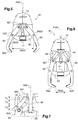
- the gripping means 30 comprise a so-called “quarter-turn” device 31 extending downward from the upper beam 12 and intended to come in. taken with an oblong window 32 formed in an upper flange 33 of the lower beam 11.
- the quarter-turn device 31 comprises in particular a slide 34, a lower dentition 35 and an upper dentition 36.
- Each dentition 35, 36 is formed on the edge of a respective hollow cylinder 37, 38; the cylinders are arranged coaxially so that the dentitions face each other.
- Each tooth 39 comprises, according to an identical direction of rotation for the two dentitions, a vertical front 41 then a slope 43 framing a point 42.
- the dentitions are arranged so that the point of a tooth 39 of one of the dentitions is opposite the slope of one tooth from the other dentition.
- the cylinders bearing the teeth are mounted crimped in a cylindrical sleeve 40 and together with this sleeve form a fixed part, relative to the upper beam 12, of the quarter-turn device.
- the slide 34 is designed to slide axially in the cylinders 37, 38 carrying the teeth 35, 36. Its lower end is formed by a gib 51, of oblong shape, provided to cooperate with the oblong window 32 of the lower beam 11. Au beyond the gib 51, from bottom to top, the slide comprises a cylindrical pin 52, a disc-shaped stop 53, then a cylindrical rod 54 slidably mounted in the cylinders carrying the teeth. The slide further comprises a key 55 which extends radially from the rod 54. The slide thus forms a movable axis capable of moving up and down in the fixed part 37, 38, 40.
- the diameter D52 of the pin 52 is such that the pin can slide in the window 32 of the lower beam 11.
- the diameter D53 of the stopper 53 is greater than the width L32 of the window 32 of the lower beam 11, so that the slider 34 cannot penetrate the beam beyond the pin 52.
- the figure 10 illustrates the operation of the quarter-turn device 31, assuming that the quarter-turn device 31 is in a so-called locked position illustrated in figure 8 .
- the gib 51 is in a transverse position inside the lower beam 11; thus, the upper beam 12, which carries the quarter-turn device 31, is engaged with the lower beam 11.
- the key 55 is in a position 55A, between two teeth of the upper dentition 36.
- the slings 27 are relaxed; the gripping system is in the open position; it remains there as long as the beams 11, 12 remain in mutual engagement thanks to the quarter-turn device.
- the lifting means V then lowering the upper beam 12, the fixed part 37, 38, 40 moves downward with the upper beam 12 while the disc 53 bears against the lower beam 11, until the The key takes a position 55D in contact with the upper dentition 36, at the bottom of the slope 43 which is opposite the position 55C.
- a successive ascent and descent of the upper beam 12 allows the slide 34 to be made a quarter turn, so that the gib is in a longitudinal position; a new lifting of the upper beam 12 makes it possible to release the gib from the lower beam 11.
- the lifter 10 can then take an unlocked position, illustrated in figure 4 , in which the slings 27 are tensioned, causing the counterweights 21 upwards and the engagement of the hooks 22 in the openings 25 provided for this purpose in the load 23.
- each end of the transverse beams 14 comprises a ring 59 for hanging a rope or a pole therein, in order to ensure the horizontal positioning of the lifter 10.
- the figure 2 illustrates a lifter 60 which differs from lifter 10 primarily because its gripping systems 61 are cam systems and not slings. Gripping systems and their operation are illustrated in detail in figures 5 to 6 .
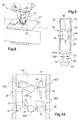
- the figure 5 illustrates one of the gripping systems 61 in the open position; the figure 6 illustrates the same system in the closed position.
- the gripping system comprises in particular two arms 62 and a slide 63 and a guide 64.
- the two arms 62 are arranged symmetrically with respect to one another with respect to the longitudinal plane P60 of symmetry of the lifter 60.
- This plane P60 is the equivalent of plane P10 of the lifting beam 10.
- the guide is rigidly fixed to the upper beam 12; It comprises two rails 64 which are symmetrical to each other with respect to the longitudinal plane P60 of symmetry of the lifter 60. As particularly illustrated in figure 7 , each rail 64 comprises, from top to bottom, a first area 641, substantially vertical, a second area 642 gradually moving away from the plane P60, and a third area 643 substantially vertical.
- the slide 63 is designed to slide vertically relative to the upper beam 12.
- the slide In the lower part, the slide is rigidly fixed to the lower beam 11, so that it slides downwards relative to the upper beam 12 when the lower beam 11 s 'moves away from the upper beam 12, and, slides upward relative to the upper beam 12 when the lower beam 11 approaches it.
- Each arm 62 comprises a first end 621 intended to travel while being guided therein the respective rail 64.
- the rail 64 has the form of a window and the first end 621 comprises a roller mounted to roll along the edges of this window.
- a second end 622 of the arm 62 includes a hook shape, adapted to engage a load to be lifted and moved.
- An intermediate point 623 of the arm is articulated with the slide 63, around a horizontal axis X623. The slide 63 imposes a fixed distance D623 between this intermediate point 623 and the intermediate point 623 of the other arm 62.
- the first end 621 is in the first zone 641 of the rail 64, so that this first end 621 is close to the first end 621 of the other arm 62.
- the first ends 621 of the arms first pass through the first zone 641 which corresponds to a first vertical stroke C1. They then traverse the second zone 642, traversing a second vertical opening stroke C2.
- the two first ends 621 gradually move away from each other; this distance causes the arms to rotate around their respective intermediate point 623, and, consequently, the second ends 622 move closer together.
- the hooks are at a reduced distance D622 from each other, and the gripping system is in the position closed illustrated in figure 6 .
- the third race C3 constitutes a safety race; that is to say that if the load or the lifting beam undergo an impact which would tend to bring the two beams 11, 12 closer together, the gripping system remains in the closed position as long as the first ends remain in the third zones 643.
- this guiding system by cam is also the fact that it provides a securing of the elements of the gripping system as well as a significant reduction in the frictional stresses which are therefore negligible. This results in complete and secure automation of the gripping system.
- the hooks in a closed position, provision can be made for the hooks to be further apart from one another than in the open position, the hooks being provided facing away from each other.
Landscapes
- Engineering & Computer Science (AREA)
- Mechanical Engineering (AREA)
- Load-Engaging Elements For Cranes (AREA)
- Conveying And Assembling Of Building Elements In Situ (AREA)
Priority Applications (1)
| Application Number | Priority Date | Filing Date | Title |
|---|---|---|---|
| PL14731687T PL2996979T3 (pl) | 2013-05-17 | 2014-05-16 | Zabezpieczony system chwytny |
Applications Claiming Priority (2)
| Application Number | Priority Date | Filing Date | Title |
|---|---|---|---|
| FR1354447 | 2013-05-17 | ||
| PCT/FR2014/051142 WO2014184502A1 (fr) | 2013-05-17 | 2014-05-16 | Systeme de prehension securise. |
Publications (2)
| Publication Number | Publication Date |
|---|---|
| EP2996979A1 EP2996979A1 (fr) | 2016-03-23 |
| EP2996979B1 true EP2996979B1 (fr) | 2021-12-22 |
Family
ID=50979801
Family Applications (1)
| Application Number | Title | Priority Date | Filing Date |
|---|---|---|---|
| EP14731687.1A Active EP2996979B1 (fr) | 2013-05-17 | 2014-05-16 | Systeme de prehension securise |
Country Status (5)
| Country | Link |
|---|---|
| US (1) | US9731942B2 (pl) |
| EP (1) | EP2996979B1 (pl) |
| CN (1) | CN105228940B (pl) |
| PL (1) | PL2996979T3 (pl) |
| WO (1) | WO2014184502A1 (pl) |
Families Citing this family (5)
| Publication number | Priority date | Publication date | Assignee | Title |
|---|---|---|---|---|
| FR3064616B1 (fr) * | 2017-03-31 | 2021-01-29 | Soc Dapplications Electriques Et Mecaniques Sapem | Palonnier a faible hauteur de travail. |
| FR3072373B1 (fr) * | 2017-10-16 | 2020-02-28 | Manitowoc Crane Group France | Procede de securisation d'un mouvement de levage d'une charge et dispositif de levage associe |
| GB201913783D0 (en) | 2019-09-24 | 2019-11-06 | Jamieson Angus | System and method for controlling the lifting and handling of a load |
| CN113120748A (zh) * | 2020-06-14 | 2021-07-16 | 新昌县苗颖园林机械有限公司 | 一种碳化硅玻璃钢管升降用起吊调节装置 |
| NO20230079A1 (en) * | 2023-01-27 | 2024-07-29 | Optimar As | Gripper assembly |
Family Cites Families (25)
| Publication number | Priority date | Publication date | Assignee | Title |
|---|---|---|---|---|
| US1506827A (en) * | 1923-12-22 | 1924-09-02 | Rolph F Gellert | Tongs and the like |
| US2342506A (en) * | 1942-07-30 | 1944-02-22 | American Car & Foundry Co | Grapple |
| US2822210A (en) * | 1956-02-16 | 1958-02-04 | Dave F Gebhart | Lifting mechanism |
| US3297353A (en) * | 1964-11-23 | 1967-01-10 | Erna L Carlson | Lifting grapple with scissors tongs for handling concrete drainage rings |
| US3306646A (en) * | 1965-07-30 | 1967-02-28 | Flexicore Company Inc | Lifting hook assembly |
| US3348872A (en) * | 1966-06-09 | 1967-10-24 | William B Kolinski | Automatic tongs |
| US3455593A (en) * | 1966-09-28 | 1969-07-15 | American Chain & Cable Co | Lifting tongs |
| US3508780A (en) * | 1968-06-17 | 1970-04-28 | American Forge & Mfg Co Inc | Control device for tongs |
| GB1224694A (en) * | 1969-03-26 | 1971-03-10 | Herbert Morris Brown Lenox Ltd | Lifting tongs |
| US3561615A (en) * | 1969-07-16 | 1971-02-09 | Terry A Forsberg | Pipe positioning and handling device |
| DE2054032C3 (de) | 1970-11-03 | 1974-07-18 | Wilhelm Scheidt, Maschinenfabrik Kg, 4307 Kettwig | Brammenzange |
| US3697117A (en) * | 1971-04-28 | 1972-10-10 | Martin Marietta Corp | Lifting tongs |
| US3942834A (en) * | 1974-06-14 | 1976-03-09 | Nittan Kohki Kabushiki Kaisha | Hooked clutch |
| JPS54129642A (en) * | 1978-03-28 | 1979-10-08 | Kobe Steel Ltd | Roll hoist |
| SE420483B (sv) * | 1979-05-09 | 1981-10-12 | Scal Sweden Ab | Lyftanordning for container eller liknande, der ett stativ eller liknande forefinnes |
| CN87203329U (zh) * | 1987-05-19 | 1988-03-02 | 大连起重机器厂 | 自动钢板坯夹钳 |
| JP2824641B1 (ja) | 1997-01-27 | 1998-11-11 | 野津運送株式会社 | 荷の挟持吊り上げ装置 |
| US5979961A (en) * | 1998-01-26 | 1999-11-09 | Carey Consulting, Inc. | Tube bundle lifting device |
| US6322120B1 (en) * | 1998-01-26 | 2001-11-27 | Carey Consulting, Inc. | Tube bundle lifting device |
| JP3332892B2 (ja) * | 1999-06-14 | 2002-10-07 | 東邦チタニウム株式会社 | 掴み力補足装置を備えたトング装置 |
| CN2597442Y (zh) * | 2003-01-23 | 2004-01-07 | 昆明钢铁集团有限责任公司第二炼钢厂 | 一种渣盆自动吊具 |
| US7455338B2 (en) * | 2005-10-07 | 2008-11-25 | Jenney Alfred P | Leveling device for lifting apparatus and associated methods |
| US8109550B1 (en) * | 2008-09-29 | 2012-02-07 | Honda Motor Co., Ltd. | Pack end tool |
| CN202245677U (zh) * | 2011-09-09 | 2012-05-30 | 西安兰石重工机械有限公司 | 旋转式吊具开闭器 |
| CN102923562B (zh) * | 2012-10-11 | 2014-11-19 | 中国核电工程有限公司 | 摆杆控制式外张自动吊具 |
-
2014
- 2014-05-16 WO PCT/FR2014/051142 patent/WO2014184502A1/fr not_active Ceased
- 2014-05-16 EP EP14731687.1A patent/EP2996979B1/fr active Active
- 2014-05-16 PL PL14731687T patent/PL2996979T3/pl unknown
- 2014-05-16 US US14/891,751 patent/US9731942B2/en not_active Expired - Fee Related
- 2014-05-16 CN CN201480028780.9A patent/CN105228940B/zh active Active
Also Published As
| Publication number | Publication date |
|---|---|
| US20160090277A1 (en) | 2016-03-31 |
| WO2014184502A1 (fr) | 2014-11-20 |
| EP2996979A1 (fr) | 2016-03-23 |
| CN105228940A (zh) | 2016-01-06 |
| CN105228940B (zh) | 2019-11-05 |
| US9731942B2 (en) | 2017-08-15 |
| PL2996979T3 (pl) | 2022-04-04 |
Similar Documents
| Publication | Publication Date | Title |
|---|---|---|
| EP2996979B1 (fr) | Systeme de prehension securise | |
| EP1473267B1 (fr) | Dispositif de lestage pour grue | |
| EP3713868B1 (fr) | Dispositif de hissage portatif | |
| FR3072589A1 (fr) | Procede de manutention d'une charge notamment une bobine de tole, dispositif de manutention permettant la mise en oeuvre dudit procede et engin de levage equipe d'un tel dispositif | |
| EP3466862A1 (fr) | Grue à flèche relevable avec dispositif de verrouillage de la flèche en configuration relevée | |
| FR2898173A1 (fr) | Crochet de levage avec reducteur de longueur de chaine | |
| FR2943047A1 (fr) | Dispositif de soulevement d'une plaque de voirie | |
| FR2527115A1 (fr) | Scie a ruban et ensemble a cassette supportant la lame d'une telle scie | |
| FR2554101A1 (fr) | Pince autoserrante avec securite de blocage pour le transport d'une charge | |
| FR3077228A1 (fr) | Systeme d’aide au dressage et a la depose d’element de construction longitudinal et vehicule de manutention d’element de construction longitudinal equipe d’un tel systeme | |
| FR3011476A1 (fr) | Dispositif de liaison deplacable et amovible le long d'une corde | |
| EP3924070B1 (fr) | Connecteur, fausse fourche largable muni d'un tel connecteur et procédé d'utilisation | |
| FR2916211A1 (fr) | Installation pour la pose de caniveaux et de couvercles | |
| FR3005946A1 (fr) | Appareil de levage d'une charge | |
| FR3050728A1 (fr) | Palonnier de levage avec support sous anneaux a elingues | |
| FR2546870A1 (fr) | Dispositif de prehension et de levage de sacs pleins | |
| EP3569774B1 (fr) | Machine d'excavation comprenant un tube de guidage permettant la rotation du chassis | |
| EP3623491B1 (fr) | Système d'arrimage de produit de type tête de bande dans un pot de revêtement et méthodes associées | |
| CA2890453A1 (fr) | Machine et procede pour l'extraction des bourrelets d'un pneumatique en fin de vie | |
| FR3095557A1 (fr) | Un système de tirage des fils ou câbles d'une caténaire notamment d'une voie de chemin de fer | |
| EP1785528B1 (fr) | Dispositif de support pour un panneau de signalisation routière | |
| FR2573462A1 (fr) | Dispositif de basculement, en particulier pour monte-materiaux | |
| FR2640605A1 (fr) | Pince mecanique autoserrante | |
| FR2976274A1 (fr) | Dispositif pour deposer des elingues en cables d'acier suspendues a un crochet | |
| EP3351704B1 (fr) | Dispositif porte plaque de matériau pour appareil de levage et de manutention permettant la pose de plaque à l'horizontale, sous rampant et à la verticale |
Legal Events
| Date | Code | Title | Description |
|---|---|---|---|
| PUAI | Public reference made under article 153(3) epc to a published international application that has entered the european phase |
Free format text: ORIGINAL CODE: 0009012 |
|
| 17P | Request for examination filed |
Effective date: 20151116 |
|
| AK | Designated contracting states |
Kind code of ref document: A1 Designated state(s): AL AT BE BG CH CY CZ DE DK EE ES FI FR GB GR HR HU IE IS IT LI LT LU LV MC MK MT NL NO PL PT RO RS SE SI SK SM TR |
|
| AX | Request for extension of the european patent |
Extension state: BA ME |
|
| RIN1 | Information on inventor provided before grant (corrected) |
Inventor name: SEVRIN, OLIVIER Inventor name: ARCHER, JOEL |
|
| DAX | Request for extension of the european patent (deleted) | ||
| RAP1 | Party data changed (applicant data changed or rights of an application transferred) |
Owner name: FRAMATOME Owner name: SOCIETE D'APPLICATIONS ELECTRIQUES ET MECANIQUES S |
|
| STAA | Information on the status of an ep patent application or granted ep patent |
Free format text: STATUS: EXAMINATION IS IN PROGRESS |
|
| 17Q | First examination report despatched |
Effective date: 20180816 |
|
| GRAP | Despatch of communication of intention to grant a patent |
Free format text: ORIGINAL CODE: EPIDOSNIGR1 |
|
| STAA | Information on the status of an ep patent application or granted ep patent |
Free format text: STATUS: GRANT OF PATENT IS INTENDED |
|
| INTG | Intention to grant announced |
Effective date: 20210716 |
|
| GRAS | Grant fee paid |
Free format text: ORIGINAL CODE: EPIDOSNIGR3 |
|
| GRAA | (expected) grant |
Free format text: ORIGINAL CODE: 0009210 |
|
| STAA | Information on the status of an ep patent application or granted ep patent |
Free format text: STATUS: THE PATENT HAS BEEN GRANTED |
|
| AK | Designated contracting states |
Kind code of ref document: B1 Designated state(s): AL AT BE BG CH CY CZ DE DK EE ES FI FR GB GR HR HU IE IS IT LI LT LU LV MC MK MT NL NO PL PT RO RS SE SI SK SM TR |
|
| REG | Reference to a national code |
Ref country code: GB Ref legal event code: FG4D Free format text: NOT ENGLISH |
|
| REG | Reference to a national code |
Ref country code: CH Ref legal event code: EP |
|
| REG | Reference to a national code |
Ref country code: DE Ref legal event code: R096 Ref document number: 602014081811 Country of ref document: DE |
|
| REG | Reference to a national code |
Ref country code: AT Ref legal event code: REF Ref document number: 1456948 Country of ref document: AT Kind code of ref document: T Effective date: 20220115 |
|
| REG | Reference to a national code |
Ref country code: IE Ref legal event code: FG4D Free format text: LANGUAGE OF EP DOCUMENT: FRENCH |
|
| REG | Reference to a national code |
Ref country code: FI Ref legal event code: FGE |
|
| REG | Reference to a national code |
Ref country code: LT Ref legal event code: MG9D |
|
| PG25 | Lapsed in a contracting state [announced via postgrant information from national office to epo] |
Ref country code: RS Free format text: LAPSE BECAUSE OF FAILURE TO SUBMIT A TRANSLATION OF THE DESCRIPTION OR TO PAY THE FEE WITHIN THE PRESCRIBED TIME-LIMIT Effective date: 20211222 Ref country code: LT Free format text: LAPSE BECAUSE OF FAILURE TO SUBMIT A TRANSLATION OF THE DESCRIPTION OR TO PAY THE FEE WITHIN THE PRESCRIBED TIME-LIMIT Effective date: 20211222 Ref country code: BG Free format text: LAPSE BECAUSE OF FAILURE TO SUBMIT A TRANSLATION OF THE DESCRIPTION OR TO PAY THE FEE WITHIN THE PRESCRIBED TIME-LIMIT Effective date: 20220322 |
|
| REG | Reference to a national code |
Ref country code: NL Ref legal event code: MP Effective date: 20211222 |
|
| REG | Reference to a national code |
Ref country code: AT Ref legal event code: MK05 Ref document number: 1456948 Country of ref document: AT Kind code of ref document: T Effective date: 20211222 |
|
| PG25 | Lapsed in a contracting state [announced via postgrant information from national office to epo] |
Ref country code: SE Free format text: LAPSE BECAUSE OF FAILURE TO SUBMIT A TRANSLATION OF THE DESCRIPTION OR TO PAY THE FEE WITHIN THE PRESCRIBED TIME-LIMIT Effective date: 20211222 Ref country code: NO Free format text: LAPSE BECAUSE OF FAILURE TO SUBMIT A TRANSLATION OF THE DESCRIPTION OR TO PAY THE FEE WITHIN THE PRESCRIBED TIME-LIMIT Effective date: 20220322 Ref country code: LV Free format text: LAPSE BECAUSE OF FAILURE TO SUBMIT A TRANSLATION OF THE DESCRIPTION OR TO PAY THE FEE WITHIN THE PRESCRIBED TIME-LIMIT Effective date: 20211222 Ref country code: HR Free format text: LAPSE BECAUSE OF FAILURE TO SUBMIT A TRANSLATION OF THE DESCRIPTION OR TO PAY THE FEE WITHIN THE PRESCRIBED TIME-LIMIT Effective date: 20211222 Ref country code: GR Free format text: LAPSE BECAUSE OF FAILURE TO SUBMIT A TRANSLATION OF THE DESCRIPTION OR TO PAY THE FEE WITHIN THE PRESCRIBED TIME-LIMIT Effective date: 20220323 |
|
| PG25 | Lapsed in a contracting state [announced via postgrant information from national office to epo] |
Ref country code: NL Free format text: LAPSE BECAUSE OF FAILURE TO SUBMIT A TRANSLATION OF THE DESCRIPTION OR TO PAY THE FEE WITHIN THE PRESCRIBED TIME-LIMIT Effective date: 20211222 |
|
| PG25 | Lapsed in a contracting state [announced via postgrant information from national office to epo] |
Ref country code: SM Free format text: LAPSE BECAUSE OF FAILURE TO SUBMIT A TRANSLATION OF THE DESCRIPTION OR TO PAY THE FEE WITHIN THE PRESCRIBED TIME-LIMIT Effective date: 20211222 Ref country code: SK Free format text: LAPSE BECAUSE OF FAILURE TO SUBMIT A TRANSLATION OF THE DESCRIPTION OR TO PAY THE FEE WITHIN THE PRESCRIBED TIME-LIMIT Effective date: 20211222 Ref country code: RO Free format text: LAPSE BECAUSE OF FAILURE TO SUBMIT A TRANSLATION OF THE DESCRIPTION OR TO PAY THE FEE WITHIN THE PRESCRIBED TIME-LIMIT Effective date: 20211222 Ref country code: PT Free format text: LAPSE BECAUSE OF FAILURE TO SUBMIT A TRANSLATION OF THE DESCRIPTION OR TO PAY THE FEE WITHIN THE PRESCRIBED TIME-LIMIT Effective date: 20220422 Ref country code: ES Free format text: LAPSE BECAUSE OF FAILURE TO SUBMIT A TRANSLATION OF THE DESCRIPTION OR TO PAY THE FEE WITHIN THE PRESCRIBED TIME-LIMIT Effective date: 20211222 Ref country code: EE Free format text: LAPSE BECAUSE OF FAILURE TO SUBMIT A TRANSLATION OF THE DESCRIPTION OR TO PAY THE FEE WITHIN THE PRESCRIBED TIME-LIMIT Effective date: 20211222 |
|
| PG25 | Lapsed in a contracting state [announced via postgrant information from national office to epo] |
Ref country code: AT Free format text: LAPSE BECAUSE OF FAILURE TO SUBMIT A TRANSLATION OF THE DESCRIPTION OR TO PAY THE FEE WITHIN THE PRESCRIBED TIME-LIMIT Effective date: 20211222 |
|
| REG | Reference to a national code |
Ref country code: DE Ref legal event code: R097 Ref document number: 602014081811 Country of ref document: DE |
|
| PG25 | Lapsed in a contracting state [announced via postgrant information from national office to epo] |
Ref country code: IS Free format text: LAPSE BECAUSE OF FAILURE TO SUBMIT A TRANSLATION OF THE DESCRIPTION OR TO PAY THE FEE WITHIN THE PRESCRIBED TIME-LIMIT Effective date: 20220422 |
|
| PLBE | No opposition filed within time limit |
Free format text: ORIGINAL CODE: 0009261 |
|
| STAA | Information on the status of an ep patent application or granted ep patent |
Free format text: STATUS: NO OPPOSITION FILED WITHIN TIME LIMIT |
|
| PG25 | Lapsed in a contracting state [announced via postgrant information from national office to epo] |
Ref country code: DK Free format text: LAPSE BECAUSE OF FAILURE TO SUBMIT A TRANSLATION OF THE DESCRIPTION OR TO PAY THE FEE WITHIN THE PRESCRIBED TIME-LIMIT Effective date: 20211222 Ref country code: AL Free format text: LAPSE BECAUSE OF FAILURE TO SUBMIT A TRANSLATION OF THE DESCRIPTION OR TO PAY THE FEE WITHIN THE PRESCRIBED TIME-LIMIT Effective date: 20211222 |
|
| 26N | No opposition filed |
Effective date: 20220923 |
|
| REG | Reference to a national code |
Ref country code: DE Ref legal event code: R119 Ref document number: 602014081811 Country of ref document: DE |
|
| REG | Reference to a national code |
Ref country code: CH Ref legal event code: PL |
|
| REG | Reference to a national code |
Ref country code: BE Ref legal event code: MM Effective date: 20220531 |
|
| PG25 | Lapsed in a contracting state [announced via postgrant information from national office to epo] |
Ref country code: MC Free format text: LAPSE BECAUSE OF FAILURE TO SUBMIT A TRANSLATION OF THE DESCRIPTION OR TO PAY THE FEE WITHIN THE PRESCRIBED TIME-LIMIT Effective date: 20211222 Ref country code: LU Free format text: LAPSE BECAUSE OF NON-PAYMENT OF DUE FEES Effective date: 20220516 Ref country code: LI Free format text: LAPSE BECAUSE OF NON-PAYMENT OF DUE FEES Effective date: 20220531 Ref country code: CH Free format text: LAPSE BECAUSE OF NON-PAYMENT OF DUE FEES Effective date: 20220531 |
|
| PG25 | Lapsed in a contracting state [announced via postgrant information from national office to epo] |
Ref country code: SI Free format text: LAPSE BECAUSE OF FAILURE TO SUBMIT A TRANSLATION OF THE DESCRIPTION OR TO PAY THE FEE WITHIN THE PRESCRIBED TIME-LIMIT Effective date: 20211222 |
|
| PG25 | Lapsed in a contracting state [announced via postgrant information from national office to epo] |
Ref country code: IE Free format text: LAPSE BECAUSE OF NON-PAYMENT OF DUE FEES Effective date: 20220516 |
|
| PG25 | Lapsed in a contracting state [announced via postgrant information from national office to epo] |
Ref country code: IT Free format text: LAPSE BECAUSE OF FAILURE TO SUBMIT A TRANSLATION OF THE DESCRIPTION OR TO PAY THE FEE WITHIN THE PRESCRIBED TIME-LIMIT Effective date: 20211222 Ref country code: DE Free format text: LAPSE BECAUSE OF NON-PAYMENT OF DUE FEES Effective date: 20221201 Ref country code: BE Free format text: LAPSE BECAUSE OF NON-PAYMENT OF DUE FEES Effective date: 20220531 |
|
| PG25 | Lapsed in a contracting state [announced via postgrant information from national office to epo] |
Ref country code: HU Free format text: LAPSE BECAUSE OF FAILURE TO SUBMIT A TRANSLATION OF THE DESCRIPTION OR TO PAY THE FEE WITHIN THE PRESCRIBED TIME-LIMIT; INVALID AB INITIO Effective date: 20140516 |
|
| PG25 | Lapsed in a contracting state [announced via postgrant information from national office to epo] |
Ref country code: MK Free format text: LAPSE BECAUSE OF FAILURE TO SUBMIT A TRANSLATION OF THE DESCRIPTION OR TO PAY THE FEE WITHIN THE PRESCRIBED TIME-LIMIT Effective date: 20211222 Ref country code: CY Free format text: LAPSE BECAUSE OF FAILURE TO SUBMIT A TRANSLATION OF THE DESCRIPTION OR TO PAY THE FEE WITHIN THE PRESCRIBED TIME-LIMIT Effective date: 20211222 |
|
| PG25 | Lapsed in a contracting state [announced via postgrant information from national office to epo] |
Ref country code: MT Free format text: LAPSE BECAUSE OF FAILURE TO SUBMIT A TRANSLATION OF THE DESCRIPTION OR TO PAY THE FEE WITHIN THE PRESCRIBED TIME-LIMIT Effective date: 20211222 |
|
| PGFP | Annual fee paid to national office [announced via postgrant information from national office to epo] |
Ref country code: FI Payment date: 20250423 Year of fee payment: 12 |
|
| PGFP | Annual fee paid to national office [announced via postgrant information from national office to epo] |
Ref country code: PL Payment date: 20250423 Year of fee payment: 12 |
|
| PGFP | Annual fee paid to national office [announced via postgrant information from national office to epo] |
Ref country code: GB Payment date: 20250521 Year of fee payment: 12 |
|
| PGFP | Annual fee paid to national office [announced via postgrant information from national office to epo] |
Ref country code: FR Payment date: 20250530 Year of fee payment: 12 |
|
| PGFP | Annual fee paid to national office [announced via postgrant information from national office to epo] |
Ref country code: CZ Payment date: 20250512 Year of fee payment: 12 |
|
| PG25 | Lapsed in a contracting state [announced via postgrant information from national office to epo] |
Ref country code: TR Free format text: LAPSE BECAUSE OF FAILURE TO SUBMIT A TRANSLATION OF THE DESCRIPTION OR TO PAY THE FEE WITHIN THE PRESCRIBED TIME-LIMIT Effective date: 20211222 |