EP2996648B1 - Valve de drainage implantable dans l' il d'un patient pour le traitement du glaucome - Google Patents
Valve de drainage implantable dans l' il d'un patient pour le traitement du glaucome Download PDFInfo
- Publication number
- EP2996648B1 EP2996648B1 EP14732388.5A EP14732388A EP2996648B1 EP 2996648 B1 EP2996648 B1 EP 2996648B1 EP 14732388 A EP14732388 A EP 14732388A EP 2996648 B1 EP2996648 B1 EP 2996648B1
- Authority
- EP
- European Patent Office
- Prior art keywords
- tube
- main body
- drain valve
- eye
- valve
- Prior art date
- Legal status (The legal status is an assumption and is not a legal conclusion. Google has not performed a legal analysis and makes no representation as to the accuracy of the status listed.)
- Not-in-force
Links
- 208000010412 Glaucoma Diseases 0.000 title claims description 27
- 239000012528 membrane Substances 0.000 claims description 28
- 210000002159 anterior chamber Anatomy 0.000 claims description 26
- 239000007943 implant Substances 0.000 claims description 13
- 238000005461 lubrication Methods 0.000 claims description 9
- 210000000795 conjunctiva Anatomy 0.000 claims description 7
- 230000001747 exhibiting effect Effects 0.000 claims description 7
- 238000003780 insertion Methods 0.000 claims description 7
- 230000037431 insertion Effects 0.000 claims description 7
- 238000007789 sealing Methods 0.000 claims description 4
- 230000004044 response Effects 0.000 claims description 2
- 239000000126 substance Substances 0.000 claims description 2
- 238000001356 surgical procedure Methods 0.000 claims 2
- 238000004026 adhesive bonding Methods 0.000 claims 1
- 210000001508 eye Anatomy 0.000 description 76
- 230000006872 improvement Effects 0.000 description 45
- 210000005252 bulbus oculi Anatomy 0.000 description 7
- 230000008901 benefit Effects 0.000 description 5
- 210000000744 eyelid Anatomy 0.000 description 4
- 230000002829 reductive effect Effects 0.000 description 4
- 210000004087 cornea Anatomy 0.000 description 3
- 208000015181 infectious disease Diseases 0.000 description 3
- 230000004410 intraocular pressure Effects 0.000 description 3
- 210000003786 sclera Anatomy 0.000 description 3
- 230000009471 action Effects 0.000 description 2
- 210000001742 aqueous humor Anatomy 0.000 description 2
- 230000003247 decreasing effect Effects 0.000 description 2
- 238000000605 extraction Methods 0.000 description 2
- 230000000284 resting effect Effects 0.000 description 2
- 230000003466 anti-cipated effect Effects 0.000 description 1
- 230000008859 change Effects 0.000 description 1
- 230000008878 coupling Effects 0.000 description 1
- 238000010168 coupling process Methods 0.000 description 1
- 238000005859 coupling reaction Methods 0.000 description 1
- 230000007547 defect Effects 0.000 description 1
- 230000001419 dependent effect Effects 0.000 description 1
- 230000000694 effects Effects 0.000 description 1
- 239000013013 elastic material Substances 0.000 description 1
- 208000030533 eye disease Diseases 0.000 description 1
- 230000000670 limiting effect Effects 0.000 description 1
- 239000007788 liquid Substances 0.000 description 1
- 230000036961 partial effect Effects 0.000 description 1
- 230000035515 penetration Effects 0.000 description 1
- 229920001296 polysiloxane Polymers 0.000 description 1
- 238000002560 therapeutic procedure Methods 0.000 description 1
Images


Classifications
-
- A—HUMAN NECESSITIES
- A61—MEDICAL OR VETERINARY SCIENCE; HYGIENE
- A61F—FILTERS IMPLANTABLE INTO BLOOD VESSELS; PROSTHESES; DEVICES PROVIDING PATENCY TO, OR PREVENTING COLLAPSING OF, TUBULAR STRUCTURES OF THE BODY, e.g. STENTS; ORTHOPAEDIC, NURSING OR CONTRACEPTIVE DEVICES; FOMENTATION; TREATMENT OR PROTECTION OF EYES OR EARS; BANDAGES, DRESSINGS OR ABSORBENT PADS; FIRST-AID KITS
- A61F9/00—Methods or devices for treatment of the eyes; Devices for putting in contact-lenses; Devices to correct squinting; Apparatus to guide the blind; Protective devices for the eyes, carried on the body or in the hand
- A61F9/007—Methods or devices for eye surgery
- A61F9/00781—Apparatus for modifying intraocular pressure, e.g. for glaucoma treatment
Definitions
- the present invention relates in general to the sector of implantable medical devices for the treatment and therapy of eye disease, and more particularly it relates to a drain valve suitable for being surgically implanted in the eye of a patient suffering from glaucoma in order to drain outwards the aqueous humour contained in the anterior chamber, between cornea and iris, of the eye, and therefore reduce the pressure of the aqueous humour inside the eye globe.
- implantable drain valves for the treatment of glaucoma which typically comprise a main body which in turn is associated with a drainage tube, connected at one end to the main body.
- the main body of the drain valve is implanted by the surgeon on the surface of the eye globe of the patient, in an area under the conjunctiva, while the drainage tube is implanted so as to penetrate with its tip inside the anterior chamber and therefore drain the aqueous humour therefrom.
- the drainage tube has a first end which is connected to the main body of the drain valve and a second distal end, opposite the one connected to the main body, which is implanted by the surgeon, during the operation, so as to perforate with its tip the surface of the eye globe and therefore penetrate inside the respective anterior chamber.
- the drain valve once implanted by the surgeon in the eye of the patient, allows, by means of the distal end of the drainage tube which penetrates the anterior chamber, the drainage of the aqueous humour from the inside to the outside of the eye globe where the aqueous humour is received by the main body of the valve, to then flow to the exterior of the same main body in an area below the conjunctiva.
- the implant of this valve with consequent drainage of the aqueous humour contained in the eye globe, is such as to reduce considerably the intraocular pressure so as to be effective in the treatment of glaucoma from which the patient is suffering.
- the respective drainage tube which is implanted in the eye of the patient so as to penetrate the interior of the eye globe, and in particular the portion, of the drainage tube, which is connected and adjacent to the main body of the valve and is therefore placed, in the surgical operation, over the external surface of the eye globe, usually has a circular section.
- this particular circular shape in section of the drainage tube is such as to generate an encumbrance, on the ocular surface, which in turn is found to be the cause of discomfort for the patient in whom the valve has been implanted, given that this encumbrance hinders the movement of the eyelids which have to close and open often to lubricate the ocular surface.
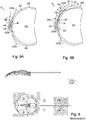
- FIG. 8 of the drawings shows a drain valve, of the conventional type and complying with the prior art, which has a drainage tube exhibiting such a circular section.
- drain valves currently available for the treatment of glaucoma do not appear such as to respond satisfactorily to some major needs and necessities which could arise and which the surgeon could have during the operation for implanting the drain valve.
- drain valves do not allow the surgeon to adapt, i.e. increase or decrease, the distance between the point wherein the drainage tube is implanted, and therefore penetrates the interior of the eye, and the valve itself, according to the specific circumstances and situations of the surgical operation to implant the valve in the eye of the patient.
- a further limit and disadvantage of known drain valves is connected to the fact that, in order to secure stably during the surgical operation the main body of the drain valve on the eye globe, the fixing holes, for the insertion of the yarn for fixing the main body of the valve on the outer surface of the eyeball, should be close, as far as possible, to the iris.
- a "Ahmed valve” is disclosed by patent document US 5,411,473 A and comprises an outer shell constituted by a pair of plates which hold in tension a membrane in turn formed by a sheet folded back on itself so as to form a chamber, of trapezoidal shape, defining an opening, similar to a slot, exhibiting an elongated shape along two edges adjacent the same membrane, wherein such opening expands and contracts in response to a change in pressure inside the chamber, and wherein the two plates of the outer shell are associated with locking elements adapted to lock the plates between them.
- this known valve comprises an inlet tube, in communication with the chamber, which extends, from the shell formed by the two plates, towards the outside of the valve and is provided to be implanted by the surgeon, at a distal end from the shell of the valve, on the surface of the eyeball so as to penetrate into the anterior chamber of the eye, and therefore to drain the aqueous humor contained in the anterior chamber towards the chamber defined by the membrane of the valve so as to control the pressure of the aqueous humor within the anterior chamber of the eye.
- the primary object of the present invention is to make a drain valve implantable in an eye for the treatment of glaucoma which is a significant improvement with respect to current valves, and in particular is suitable for effectively remedying the various and numerous disadvantages, such as those previously listed and discussed, which afflict in fact the known drain valves currently applied in the medical field for the treatment of glaucoma and therefore considerably limit the performances and the efficacy thereof.
- a further object of the present invention is also that of making a drain valve for the treatment of glaucoma which can be implanted easily on the eye of a patient and offers moreover greater and wider possibilities of action for the surgeon during the phase of implant of the valve, with respect to the valves known and applied, and for example gives the possibility to the surgeon of varying and adapting, taking account of the specific configuration of the eye globe, the distance between the main body of the valve fixed on the surface of the eye globe, under the conjunctiva, and the point wherein the drainage tube is implanted with its tip in order to penetrate the interior of the eye globe.
- a drain valve in accordance with the present invention, implantable surgically in the eye O of a patient, in order to treat glaucoma, and in particular having the function of draining the aqueous humour UA contained in the anterior chamber CA of the eye globe GO, between cornea COR and iris IR, is denoted overall by 10.
- FIG. 9A shows schematically the zone of the eye O, with the parts previously mentioned, which is provided for receiving and in which is implanted the drain valve 10 of the invention.
- drain valve 10 comprises:
- the main body 11 is designed to be fixed by the surgeon on the outer surface of the eye globe GO of the eye O, incising the sclera or scleral sac SC in an area under the conjunctiva CON which covers the same eye globe GO.
- the drainage tube 12 in turn is provided to be positioned by the surgeon on the outer surface of the eye globe GO and to be implanted in the eye so as to penetrate, with its end or tip opposite the one connected with said main body 11, inside the eye globe GO in the respective anterior chamber CA, formed between the cornea COR and the iris IR of the eye O.
- aqueous humour UA is drained from the anterior chamber CA towards the exterior of the eye globe GO, passing through the drainage tube 12 and the main body 11 of the drain valve 10, to then finally flow outside of the main body 11 in the area under the conjunctiva CON.
- drainage tube 12 can comprise:
- the first portion of the drainage tube 12, adjacent to the main body 11, extends inside the main body 11 to connect to a membrane valve device, denoted in general by 13, housed inside the same main body 11.
- the membrane device 13 comprises an elastic membrane 13a, constituted by a sheet of elastic material folded in two, wherein this elastic membrane 13a is placed between two small plates 13b and 13c housed in an outer shell of the main body 11 and reciprocally centred by means of a series of reference pegs or pins 13d.
- the sheet folded in two of the elastic membrane 13a forms in turn an inner chamber which is connected and is in communication, in the zone of folding of the sheet, with the drainage tube 12, so as to receive the aqueous humour UA coming and drained from the anterior chamber CA.
- the elastic membrane 13a housed inside the main body 11, receives and is subject also to the pressure of the aqueous humour UA coming from the anterior chamber CA, so that it reacts to this pressure by deforming, between the two small plates 13b and 13c, so as to open or close a crack formed by the folded sheet, in the zone opposite to that of the folding, and therefore regulate the flow, i.e. the drainage, as indicated by an arrow f in Fig. 1A of the aqueous humour UA from the anterior chamber CA outside of the main body 11 of the drain valve 10.
- the folded membrane 13a is completely smooth and therefore does not have, like instead the membrane of conventional drain valves, reference holes suitable for co-operating with corresponding small reference pegs or pins in order to position the same folded membrane 13a with respect to the small plates 13b and 13c between which it is housed.
- the drain valve 10 once implanted by the surgeon on the eye of the patient, is able to diminish, thanks to the action of drainage of the aqueous humour from the inside towards the outside of the eye globe, the intraocular pressure which constitutes one of the negative effects of glaucoma.
- the drain valve 10 of the invention is characterised by a series of significant improvements, which will be described here below.
- the drainage tube 12 of the drain valve 10 of the invention has a telescopic or extractable configuration comprising a first outer tube, denoted by 12a and also referred to as outer sheath, connected at a respective end 12a' to the main body 11 of the valve 10 and to the respective membrane valve device 13, and a second inner tube, denoted by 12b and also referred to as distal tube, suitable for sliding in the outer tube 12a, as indicated by a double arrow fl, and therefore also for being variably extracted from the same first outer tube 12a.
- the second inner or distal tube 12b is constituted by a first portion 12b', sliding in the outer tube 12a, and by a second portion or intraocular tube, denoted by 12f and exhibiting in section a circular shape, which is grafted at an angle ⁇ of approximately 45°, i.e. an angle ⁇ of 135° according to how it is measured, as also shown in Fig. 2F , on one end, of the first portion 12b', opposite that which slides in the outer tube 12a.
- the intraocular tube 12f in turn constitutes the tip portion, of the inner or distal tube 12b, which is implanted by the surgeon in order to penetrate the anterior chamber CA and drain the aqueous humour.
- this extractable configuration of the drainage tube 12 has the advantage of allowing the surgeon to vary and adapt, during the operation to implant the valve, the distance between the respective main body 11 and the point wherein the drainage tube 12 is implanted on the surface of the eye globe GO to penetrate its interior.
- a gasket 12c is associated with the end, of the inner tube 12b, sliding in the outer tube 12a, so as to ensure the sealing between the two outer 12a and inner 12b tubes of the drainage tube 12.
- this gasket 12c also has a function of abutment or travel stop, so as to prevent the inner tube 12b from exiting and separating from the outer tube or outer sheath 12a, during the relative sliding between these two tubes 12a and 12b.
- the outer tube 12a adjacent to the main body 11, is connected at one end via an insert 12d with the membrane valve device 13 housed inside the main body 11 so as to convey into the membrane valve device 13 the aqueous humour UA drained by the drainage tube 12.
- Fig. 2F shows schematically the configuration assumed by the drainage tube 12 in its smallest elongation, with the inner tube 12b completely withdrawn and retracted in the outer tube 12a.
- Fig. 2G shows instead schematically the configuration which is assumed by the drainage tube 12, when it has its maximum elongation, in which the inner tube 12b abuts at one end, with the respective gasket 12c, against a ridge 12a", in turn formed by a narrowing at one end of the outer tube or outer sheath 12a.
- the gasket 12c associated with the inner tube 12b, allows advantageously a decrease in the friction forces between the outer surface of the same tube 12b and the inner one of the outer tube 12a, and also prevents the inner tube 12b from exiting and uncoupling from the outer one 12a.
- the surgeon should he or she have the need, after having implanted the main body 11 of the valve 11, to elongate or adapt the length of the drainage tube 12, has only to pull and extract with pliers the second inner tube 12b, or to slide in the direction required the second tube 12b in the first tube 12a.
- surgeon once the correct extraction length of the second inner tube 12b has been established, can insert and implant in the eye of the patient the tip of the portion, projecting from the outer tube 12a, of the same inner tube 12b, so that it penetrates the interior of the anterior chamber CA.
- the surgeon after having adapted the length of the drainage tube 12, inserts and implants in the eye of the patient the intraocular tube 12f, which corresponds to the tip portion of the second inner tube 12b and is orientated at an angle ⁇ of approximately 45°, as shown in Fig. 2F , with respect to the remaining portion 12b' of the same second tube 12b.
- Second improvement drainage tube with reduced radial dimension
- the drainage tube 12 of the drain valve 10 of the invention has in section, instead of a circular shape as in the valves of the prior art, a flattened or flat shape denoted by 12', suitable for decreasing, at the same sectional area available for the drainage flow of the aqueous humour UA, the dimension IR in the radial direction of the drainage tube 12 with respect to the surface of the eye globe GO.
- this flattened shape in section can be made with an elliptical section shape, assumed both by the first outer tube 12a, directly connected to the main body 11 of the drain valve 10, and by the inner tube 12b, sliding in the tube 12a, or by only one of them.
- FIGs. 3A-3E show from several observation points and with different enlargements this second improvement, in the form wherein both the outer tube 12a and the inner tube 12b, sliding in the latter, exhibit a flattened shape in section.
- the flattened shape in section 12' of the drainage tube 12 can be formed also when the drainage tube 12 does not have the telescopic and extractable structure, described previously, corresponding to the first improvement, i.e. when the drainage tube 12 is formed by a single tube without reciprocally sliding parts.
- the drainage tube 12 exhibiting in section such a flattened configuration 12', is rested by the surgeon on the outer surface S of the eyeball GO, in such a way that the flat part of the drainage tube 12 is that which effectively comes into contact with the ocular surface.
- this second improvement defining a flat or flattened shape of the drainage tube 12 is associated with major and tangible advantages both during the performance of the surgical operation to implant the drain valve 10 and subsequently in the effective use of the drain valve of the valve 10, once implanted in the patient suffering from glaucoma, such as for example:
- This third improvement relates to the zone of the intraocular tube 12f and in particular the zone of connection and of grafting, orientated at an angle of 45° or 135° as described previously, between the portion 12b', of the inner tube 12b, which is suitable for sliding in the outer tube 12a of the drainage tube 12 and exhibits in section the flattened shape 12' corresponding to the second improvement described previously, and the intraocular tube 12f, exhibiting a circular section, which is in turn provided in order to be implanted by the surgeon so as to penetrate with its tip 12f', having a tapered and sharp shape, inside the anterior chamber CA in order to drain the aqueous humour UA.
- the present third embodiment is characterised, as clearly shown in Figs. 4A and 4B , in that the connection between the portion or intraocular tube 12f and the other remaining portion 12b' of the inner tube 12b, sliding, is made by forming, on the surface of this other portion 12b', a blind hole 12e having a diameter exactly corresponding to that of the intraocular cylindrical tube 12f; inserting in the hole 12e the end, opposite the tip 12f', of the intraocular tube 12f; and creating a seal or a coupling, in the zone of this hole 12e, between the intraocular tube 12f, and the remaining portion 12b' of the inner tube 12b.
- this third improvement allows advantageously a connection to be obtained between the intraocular tube 12f, of circular section, and the remaining part of the sliding inner tube 12b, in turn exhibiting in section the flat shape 12', with the intraocular tube 12f extended at an angle of approximately 135° with respect to this remaining part of the tube 12b, having a reduced radial and transverse dimension and in particular such as not to involve and not to have any additional encumbrance with respect to the shape of the same intraocular tube 12f and of the remaining part 12b' of the tube 12b in this connection zone.
- this third improvement remedies the disadvantage, which can be found in the known drain valves, of the encumbrance which is usually present in the zone of connection between the intraocular tube and the remaining part of the drainage tube, so that this third improvement eliminates the discomfort which such an encumbrance can cause the patient due to the obstacle which it creates to the movement of the eyelids.
- the intraocular tube 12f has a rigidity greater than that of the remaining portion 12b', instead flexible, of the inner or distal tube 12b, so as to facilitate the insertion by the surgeon of the intraocular tube 12f in the anterior chamber CA.
- this third improvement also includes one or more incisions or cuts, denoted by 12g, which are formed along the outer cylindrical surface of the intraocular tube 12f and have the function of preventing the outflow of the same intraocular tube 12f, once implanted, from the eye.
- Figs. 4D and 4F also highlight the flattened shape, cut with a slant of approximately 45° with respect to the axis of the intraocular tube 12f, of the tip end 12f, of the latter, intended to perforate the eye globe.
- This fourth improvement is aimed at improving and encouraging substantially the circulation of the aqueous humour, and consequently also the lubrication by the latter, in the area of resting and contact of the lower or soffit surface of the main body 11 of the drain valve 10 with the eye globe, so as to increase the adherence between these two parts and avoid the onset of infections.
- this fourth improvement comprises, as shown in Figs. 5A-5F in some respective embodiments, a series of through holes, denoted by 11 a, in particular three, which extend and are formed through the main body 11 of the drain valve 10, and which therefore have the function of placing in communication the surface of the eye globe, whereon the lower or soffit surface S" rests of the main body 11 of the drain valve 10 when it is implanted, and the upper or extrados surface S' of the same main body 11, opposite the lower one S", soffit, in contact with the eye globe GO.
- these through holes 11 a allow an effective circulation of the aqueous humour from the upper or extrados surface S' of the main body 11, which is the area where the aqueous humour drained by the valve and coming from inside the eye globe is poured, to lubricate the area of resting and contact of the main body 11 with the eye globe.
- this fourth improvement comprises, in order to improve further the lubrication of the area of contact between the main body 11 and the eye globe GO and therefore the adherence between these two parts, a series of compartments or recesses or bags, also referred to as retaining bags, denoted by 11b, which are formed along the lower or soffit surface S" of the main body 11 of the drain valve 10, which is placed in contact with the surface S of the eye globe GO, wherein each of these bags or compartments 11b is associated and formed at the base of a respective through hole 11 a which extends through the main body 11 of the drain valve 10 of the invention.
- these bags or compartments 11b formed at the base of the through holes 11a, are suitable both for receiving a larger quantity of aqueous humour UA and for retaining it longer in time before it flows back, so as to facilitate and improve considerably the lubrication of the eye globe in the zone of the drain valve, after it has been implanted, and in particular lubricate a larger surface of the eye globe, with respect to known and commercially available valves which do not comprise these compartments, at the base of every through hole.
- this fourth improvement of the drain valve 10 of the invention allows a considerably improved lubrication of the zone of the eye, including the eye globe, in which the valve 10 is implanted, so as to reduce considerably the risk of infections in this zone with respect to the known and currently used valves.
- These retaining compartments or bags 11b, formed at the base of the through holes 11a, can take on various shapes and configurations and extend in various ways along the soffit surface S" of the valve body 11, always remaining within the scope of this fourth improvement.
- compartments 11b can take on a substantially circular configuration, at the base of each through hole 11a, as shown in Figs. 5A and 5B , or they can take on an elongated configuration in the longitudinal direction of the valve body 11, as shown in Figs. 5C-5F .
- the upper or extrados face or surface S' of the main body 11 of the valve 10, opposite the lower or soffit surface S" of the main body 11, provided to be in contact and rest on the outer surface S of the eye globe GO, has an opening, denoted by 11c, defined by a divergent recess with fan configuration.
- This opening 11c is suitable both for facilitating the flow and the evacuation of the aqueous humour (UA) from the valve device 12, housed inside the main body 11 towards the upper or extrados surface S', of the main body 11, and to channel the aqueous humour UA, through the through holes 11 a, towards the soffit S" of the main body 11 in contact with the surface S of the eye globe GO, so as to facilitate and improve the lubrication of the eyeball and of the other parts of the eye in the area adjacent to the drain valve 10.
- UA aqueous humour
- this opening 11c replaces advantageously the ribs present in known valves, so that the extrados S' of the main body 11 does not have any protuberance but a substantially smooth and even surface and is moreover, as previously mentioned, such as to improve the lubrication of the zone or the extrados S' of the same main body 11.
- this fifth improvement replacing the ribs with recesses, eliminates the disadvantage and the problem of the discomfort of the patient which these ribs create in conventional drain valves, these ribs being, due to their projection, an obstacle to the movement of the eyelids.
- the drain valve 10 of the invention and in particular the respective main body 11 are characterised by a configuration, modified with respect to that of conventional drain valves, which allows the surgeon, in the operation for implanting the drain valve, to arrange the holes, for the insertion of the yarn for fixing the drain valve 10 to the surface S of the eye globe GO, in an adjacent position or closer to the iris of the eye, with respect to what is allowed by conventional drain valves.
- this new configuration of the drain valve 10, which is in fact made by elongating the relative main body 11 with respect to that of conventional valves, is such that the fixing holes, denoted by 11d, for the passage of the suture yarn of the drain valve 10 on the surface S of the eye globe, can be advantageously positioned by the surgeon at a distance closer by about 4 mm to the iris, with respect to conventional drain valves.
- Fig. 7A shows this new configuration of the drain valve 10, which as anticipated previously is characterised in that the respective containing body 11 comprises an additional portion 11', of length ⁇ L, with respect to conventional drain valves, in which this additional portion 11' has the fixing holes 11d for the passage of the suture yarn, so as to allow, in the surgical operation, an adjacent arrangement thereof with respect to the iris of the eye.
- Fig. 7C in turn shows a conventional drain valve VC with the respective fixing holes, denoted by FF, which does not allow the aforesaid adjacent arrangement.
- This sixth improvement is associated with multiple advantages and in particular facilitates the performance of the operation by the surgeon and also allows an optimal and improved anchorage of the drain valve to the surface of the eyeball.
- the surgeon fixes and implants the main body 1 1 of the valve 10 in the sclera or scleral sac SC and thanks to the extractable configuration of the drainage tube 12 slides as required the respective inner tube 12b, as indicated by a double arrow fl, so as to adapt the length of the drainage tube 12 to the configuration of the eye globe GO and at the point in which the surgeon wants to implant the drainage tube 12 to penetrate with its tip the anterior chamber CA.
- Fig. 9B shows the drain valve 10 of the invention, once it has been implanted by the surgeon in the eye O, in order to treat the glaucoma from which the patient is suffering.
- drain valve 10 of the present invention achieves in full all the objects which it had set.
Landscapes
- Health & Medical Sciences (AREA)
- Ophthalmology & Optometry (AREA)
- Animal Behavior & Ethology (AREA)
- Engineering & Computer Science (AREA)
- Biomedical Technology (AREA)
- Heart & Thoracic Surgery (AREA)
- Vascular Medicine (AREA)
- Life Sciences & Earth Sciences (AREA)
- General Health & Medical Sciences (AREA)
- Public Health (AREA)
- Veterinary Medicine (AREA)
- Surgery (AREA)
- Nuclear Medicine, Radiotherapy & Molecular Imaging (AREA)
- Prostheses (AREA)
- External Artificial Organs (AREA)
Claims (9)
- Valve de drainage (10) pour le traitement du glaucome, implantable par voie chirurgicale dans l'oeil (O) d'un patient, comprenant :- un corps principal (11) dans lequel vient se loger un dispositif (13) faisant office de valve à membrane ; et- un tube de drainage (12) relié à une extrémité (12a') audit corps principal (11) et au dispositif respectif (13) faisant office de valve à membrane ;dans laquelle le corps principal (11) est conçu pour être implanté par un chirurgien sur une surface externe du globe oculaire (GO) dans une zone sous-jacente à la conjonctive (C) ;
dans laquelle le tube de drainage (12) est approprié pour être placé par le chirurgien sur la surface externe du globe oculaire et pour être implanté dans l'oeil de façon à pénétrer, avec son extrémité (12f, 12f') opposée à celle adjacente et reliée au corps principal (11), à l'intérieur de la chambre antérieure (CA) du globe oculaire (GO) dans le but de drainer et d'acheminer, depuis la chambre antérieure (CA) jusqu'au dispositif (13) faisant office de valve à membrane, l'humeur aqueuse (UA) ; et
dans laquelle le dispositif (13) faisant office de valve à membrane, logé dans le corps principal (11), est approprié pour régler le drainage, en direction de l'extérieur, de l'humeur aqueuse (UA) contenue dans ladite chambre antérieure (CA) et acheminée par le tube de drainage (12) ;
la valve de drainage (10) étant caractérisée en ce que le tube de drainage (12) possède une configuration télescopique comprenant un premier tube externe (12a) relié à une extrémité (12a') au corps principal (11) et au dispositif (13) faisant office de valve à membrane de la valve de drainage, et un second tube interne (12b) approprié pour coulisser (f1) et ainsi être extrait du tube externe (12a) pour permettre au chirurgien de faire varier et d'adapter (f1), au cours de l'opération d'implantation de la valve de drainage (10), la longueur du tube de drainage (12) en fonction de la distance entre le corps principal (11) de la valve de drainage et l'endroit auquel le tube de drainage (12) doit être implanté sur la surface du globe oculaire pour pénétrer à l'intérieur de la chambre antérieure (CA) ;
en ce que le second tube interne (12b) possède une portion en pointe constituée d'un tube intraoculaire (12f) prévu pour son implantation dans l'oeil de façon à pénétrer à l'intérieur de la chambre antérieure (CA) du globe oculaire (GO) ;
en ce que le tube intraoculaire (12f) est greffé en formant un angle de 135° sur la partie restante (12b'), coulissant (f1) dans le premier tube externe (12a), du second tube interne (12b), et possède une rigidité supérieure à celle de la partie restante (12b') du tube interne (12b) ;
en ce que le tube de drainage (12) comprend un joint d'étanchéité statique (12c) réalisé en une seule pièce avec le tube interne (12b) et intercalé entre le dernier cité et le tube externe (12a) dans le but de garantir l'étanchéisation du tube de drainage (12) par rapport au débordement de l'humeur aqueuse (UA) ;
en ce que, dans le coulissement relatif (f1) du tube interne (12b) par rapport au tube externe (12a), le joint d'étanchéité statique (12c) réalisé en une seule pièces avec le tube interne (12b), est approprié pour venir buter contre une nervure ou un rétrécissement (12a") formé à une extrémité du tube externe (12a) dans le but de limiter le coulissement et la course du second tube interne (12b) par rapport au premier tube externe (12a) ; et
en ce que le corps principal (11) de la valve de drainage (10) possède une série de trous de passage (11a) ayant pour fonction de mettre en communication le soffite (S") du corps principal (11) et ainsi la surface (S) du globe oculaire (GO) sur laquelle s'appuie le corps principal en bas, et l'extrados (S') du même corps principal (11), le soffite (S") du corps principal (11) de la valve, prévu pour s'appuyer sur la surface externe (S) du globe oculaire (GO) et pour coopérer avec ladite surface, possédant, à la base et autour de chacun de trous de passage (11 a), un sac de retenue (11 b) approprié pour recevoir et retenir l'humeur aqueuse (UA), de façon à améliorer la lubrification de la zone de contact entre le corps principal (11) et le globe oculaire, et par conséquent l'adhérence entre ces deux parties ; et
dans laquelle l'extrados (S') du corps principal (11) de la soupape de drainage (10) possède une ouverture (11 c), définie par un évidement divergent et en forme d'éventail, appropriée pour faciliter à la fois l'écoulement et l'évacuation de l'humeur aqueuse (UA) depuis l'intérieur en direction de l'extérieur (S') du corps principal (11) et la canalisation de l'humeur aqueuse à travers lesdits trous de passage (11a) en direction du soffite (S") du corps principal (11) en contact avec la surface (S) du globe oculaire (GO), de façon à faciliter et à améliorer la lubrification du globe oculaire et des autres parties de l'oeil dans la zone qui entoure la valve de drainage (10). - Valve de drainage (10) pour le traitement du glaucome selon la revendication 1, dans laquelle le tube de drainage (12, 12a, 12b) possède une configuration aplatie ou plate en coupe (12') de façon à diminuer, dans la même zone en coupe disponible pour l'écoulement de drainage de l'humeur aqueuse (UA), la dimension (IR) dans la direction radiale du tube de drainage (12) par rapport à la surface du globe oculaire (GO).
- Valve de drainage (10) pour le traitement du glaucome selon la revendication 2, dans laquelle la configuration aplatie (12') est définie par une configuration elliptique en coupe de l'un de l'autre du premier tube externe (12a) et du second tube interne (12b) du tube de drainage (12), ou des deux.
- Valve de drainage (10) pour le traitement du glaucome selon l'une quelconque des revendications précédentes, caractérisée en ce que la liaison greffée entre la partie restante (12b'), coulissant (f1) dans le premier tube externe (12a), du second tube interne (12b), et le tube intraoculaire (12f) possède un trou (12e) qui est formé sur la surface de la partie restante (12b') du second tube interne (12b) et dans lequel est insérée une extrémité du tube intraoculaire (12f), et un joint d'étanchéité ou un collage dans la zone dudit trou (12e) entre la partie restante (12b') et le tube intraoculaire (12f), et en ce que l'extrémité (12b") de la partie restante (12b') du second tube interne (12b), adjacente à la zone de la liaison entre la partie restante (12b') et le tube intraoculaire (12f), est fermée avec une substance d'étanchéisation.
- Valve de drainage (10) pour le traitement du glaucome selon l'une quelconque des revendications précédentes, caractérisée en ce que la valve de drainage (10) possède une configuration comprenant une portion supplémentaire (11') du corps principal (11) de la valve, présentant les trous de fixation (11 d) et telle qu'elle allonge (ΔL) la longueur du corps principal (11) de la valve (12), la configuration permettant, au cours de l'opération d'implantation de la valve, un arrangement, plus proche de l'iris, des trous de fixation (11 d) pour l'insertion du fil destiné à la fixation de la valve de drainage à la surface du globe oculaire (GO).
- Valve de drainage (10) pour le traitement du glaucome selon l'une quelconque des revendications précédentes, dans laquelle le tube de drainage est relié, à une extrémité, via un insert (12d), à la membrane (13a) d'un dispositif (13) faisant office de valve à membrane logé au sein du corps principal (11) de la valve de drainage (10).
- Valve de drainage (10) pour le traitement du glaucome selon l'une quelconque des revendications précédentes, dans laquelle le dispositif (13) faisant office de valve à membrane logé au sein du corps principal (11) comprend à son tour une membrane élastique (13a) appropriée pour recevoir la pression de l'humeur aqueuse (UA) émanant de la chambre antérieure (CA) du globe oculaire et pour régler, en réponse, l'écoulement de l'humeur aqueuse (UA) à l'extérieur de la valve de drainage (10), et dans laquelle la membrane (13a) est exempte de trous pour son positionnement à l'intérieur du dispositif (13) faisant office de valve à membrane.
- Valve de drainage (10) pour le traitement du glaucome selon l'une quelconque des revendications précédentes, dans laquelle le sac de retenue (11b) possède une configuration circulaire autour de la base du trou de passage respectif (11a) ou une configuration allongée sur l'étendue longitudinale du corps principal (11) de la valve.
- Valve de drainage (10) pour le traitement du glaucome selon l'une quelconque des revendications précédentes, dans laquelle le tube intraoculaire (12f) englobe une ou plusieurs découpes (12g) qui sont formées le long de sa surface externe et qui ont pour fonction d'empêcher le débordement du même tube intraoculaire (12f) une fois implanté, à partir de l'oeil, et dans laquelle l'extrémité en pointe (12f') du tube intraoculaire (12f), destinée à perforer le globe oculaire, présente une configuration aplatie, découpée avec une inclinaison d'approximativement 45° par rapport à l'axe du tube intraoculaire (12f).
Applications Claiming Priority (2)
| Application Number | Priority Date | Filing Date | Title |
|---|---|---|---|
| IT000783A ITMI20130783A1 (it) | 2013-05-13 | 2013-05-13 | Valvola di drenaggio migliorata impiantabile nell'occhio di paziente per il trattamento del glaucoma |
| PCT/IB2014/061378 WO2014184725A1 (fr) | 2013-05-13 | 2014-05-12 | Valve de drainage implantable dans l'œil d'un patient pour le traitement du glaucome |
Publications (2)
| Publication Number | Publication Date |
|---|---|
| EP2996648A1 EP2996648A1 (fr) | 2016-03-23 |
| EP2996648B1 true EP2996648B1 (fr) | 2017-06-28 |
Family
ID=48748365
Family Applications (1)
| Application Number | Title | Priority Date | Filing Date |
|---|---|---|---|
| EP14732388.5A Not-in-force EP2996648B1 (fr) | 2013-05-13 | 2014-05-12 | Valve de drainage implantable dans l' il d'un patient pour le traitement du glaucome |
Country Status (17)
| Country | Link |
|---|---|
| US (1) | US9561133B2 (fr) |
| EP (1) | EP2996648B1 (fr) |
| JP (1) | JP2016532458A (fr) |
| KR (1) | KR20160016782A (fr) |
| CN (1) | CN105377202A (fr) |
| AR (1) | AR096263A1 (fr) |
| AU (1) | AU2014266901A1 (fr) |
| BR (1) | BR112015028375A2 (fr) |
| CA (1) | CA2912371A1 (fr) |
| ES (1) | ES2634521T3 (fr) |
| HK (1) | HK1222116A1 (fr) |
| IT (1) | ITMI20130783A1 (fr) |
| MA (1) | MA38581B1 (fr) |
| MX (1) | MX2015015627A (fr) |
| RU (1) | RU2015148449A (fr) |
| TN (1) | TN2015000502A1 (fr) |
| WO (1) | WO2014184725A1 (fr) |
Cited By (7)
| Publication number | Priority date | Publication date | Assignee | Title |
|---|---|---|---|---|
| US10617558B2 (en) | 2012-11-28 | 2020-04-14 | Ivantis, Inc. | Apparatus for delivering ocular implants into an anterior chamber of the eye |
| US10709547B2 (en) | 2014-07-14 | 2020-07-14 | Ivantis, Inc. | Ocular implant delivery system and method |
| US11197779B2 (en) | 2015-08-14 | 2021-12-14 | Ivantis, Inc. | Ocular implant with pressure sensor and delivery system |
| US11540940B2 (en) | 2021-01-11 | 2023-01-03 | Alcon Inc. | Systems and methods for viscoelastic delivery |
| US11744734B2 (en) | 2007-09-24 | 2023-09-05 | Alcon Inc. | Method of implanting an ocular implant |
| US11938058B2 (en) | 2015-12-15 | 2024-03-26 | Alcon Inc. | Ocular implant and delivery system |
| US12029683B2 (en) | 2018-02-22 | 2024-07-09 | Alcon Inc. | Ocular implant and delivery system |
Families Citing this family (19)
| Publication number | Priority date | Publication date | Assignee | Title |
|---|---|---|---|---|
| US10342702B2 (en) | 2014-08-29 | 2019-07-09 | Camras Vision Inc. | Apparatus and method for reducing intraocular pressure |
| US10201451B2 (en) | 2014-08-29 | 2019-02-12 | Camras Vision Inc. | Device and method for reducing intraocular pressure |
| US10524958B2 (en) | 2015-09-30 | 2020-01-07 | Alievio, Inc. | Method and apparatus for reducing intraocular pressure |
| US10987033B2 (en) * | 2015-11-11 | 2021-04-27 | Microoptx Inc. | Aqueous humor monitoring devices and methods |
| WO2017122837A1 (fr) * | 2016-01-12 | 2017-07-20 | 황규덕 | Régulateur de pression intraoculaire comprenant un organe de régulation de pression |
| EP3463226B1 (fr) | 2016-06-03 | 2020-08-05 | New World Medical, Inc. | Dispositif de drainage intraoculaire |
| RU171314U1 (ru) * | 2016-09-29 | 2017-05-29 | Федеральное государственное бюджетное образовательное учреждение высшего образования "Национальный исследовательский Мордовский государственный университет им. Н.П. Огарёва" | Мандрен для фиксации клапана ahmed в переднюю камеру глаза |
| US11523940B2 (en) | 2017-03-17 | 2022-12-13 | W. L. Gore & Associates, Inc. | Delivery aids for glaucoma shunts |
| US20200229978A1 (en) * | 2017-08-11 | 2020-07-23 | University Of Florida Research Foundation, Incorporated | Enhanced drainage of failed glaucoma drainage device (gdd) |
| JP7385563B2 (ja) * | 2017-10-23 | 2023-11-22 | ザ リージェンツ オブ ザ ユニバーシティ オブ コロラド,ア ボディー コーポレイト | 二重切開のための眼内デバイス |
| KR102190257B1 (ko) | 2017-12-20 | 2020-12-16 | 주식회사 마이크로트 | 안압의 조절을 위한 안질환용 임플란트 장치 |
| AU2019333136B2 (en) | 2018-08-29 | 2022-11-17 | W. L. Gore & Associates, Inc. | Drug therapy delivery systems and methods |
| ES2882522T3 (es) * | 2018-12-12 | 2021-12-02 | Ajl Ophthalmic S A | Dispositivo de implante de glaucoma |
| DE102019126959A1 (de) * | 2019-10-08 | 2021-04-08 | Implandata Ophthalmic Products Gmbh | Anordnung zur in vivo Veränderung eines Augeninnendrucks |
| KR102450970B1 (ko) * | 2020-09-17 | 2022-10-04 | 한양대학교 산학협력단 | 방수유출장치 및 그 제조방법 |
| KR102574844B1 (ko) * | 2020-11-30 | 2023-09-07 | 주식회사 마이크로트 | 전방 내 형성 압력이 조절된 안질환용 임플란트 장치 |
| US12544262B2 (en) | 2021-11-05 | 2026-02-10 | W. L. Gore & Associates, Inc. | Fluid drainage devices, systems, and methods |
| US12527691B2 (en) | 2021-11-05 | 2026-01-20 | W. L. Gore & Associates, Inc. | Fluid drainage devices, systems, and methods |
| CN119012987A (zh) * | 2022-03-29 | 2024-11-22 | W.L.戈尔及同仁股份有限公司 | 生物流体分流装置和方法 |
Family Cites Families (12)
| Publication number | Priority date | Publication date | Assignee | Title |
|---|---|---|---|---|
| US5743869A (en) * | 1988-10-07 | 1998-04-28 | Ahmed; Abdul Mateen | Medical device and method for treating ascites |
| US5071408A (en) * | 1988-10-07 | 1991-12-10 | Ahmed Abdul Mateen | Medical valve |
| US5476445A (en) * | 1990-05-31 | 1995-12-19 | Iovision, Inc. | Glaucoma implant with a temporary flow restricting seal |
| US5171213A (en) * | 1991-08-14 | 1992-12-15 | Price Jr Francis W | Technique for fistulization of the eye and an eye filtration prosthesis useful therefor |
| US5549579A (en) * | 1992-11-20 | 1996-08-27 | Specialty Silicone Fabricators | Unitary drain and method for making |
| US5433701A (en) * | 1994-12-21 | 1995-07-18 | Rubinstein; Mark H. | Apparatus for reducing ocular pressure |
| CN2237430Y (zh) * | 1995-07-20 | 1996-10-16 | 北京市橡胶制品设计研究院 | 青光眼房水引流盘 |
| US20040162545A1 (en) * | 2003-02-14 | 2004-08-19 | Brown J. David | Bypass for glaucoma drainage device |
| US7025740B2 (en) * | 2003-04-22 | 2006-04-11 | Ahmed A Mateen | Device for treating glaucoma & method of manufacture |
| US20050267398A1 (en) * | 2004-05-27 | 2005-12-01 | Dimitri Protopsaltis | Glaucoma shunt |
| US8702639B2 (en) * | 2009-03-26 | 2014-04-22 | Abbott Medical Optics Inc. | Glaucoma shunts with flow management and improved surgical performance |
| CN201631477U (zh) * | 2010-03-06 | 2010-11-17 | 修方伟 | 青光眼微创房水引流植入物 |
-
2013
- 2013-05-13 IT IT000783A patent/ITMI20130783A1/it unknown
-
2014
- 2014-05-12 CA CA2912371A patent/CA2912371A1/fr not_active Abandoned
- 2014-05-12 JP JP2016513475A patent/JP2016532458A/ja active Pending
- 2014-05-12 MX MX2015015627A patent/MX2015015627A/es unknown
- 2014-05-12 ES ES14732388.5T patent/ES2634521T3/es active Active
- 2014-05-12 AR ARP140101911A patent/AR096263A1/es unknown
- 2014-05-12 US US14/890,487 patent/US9561133B2/en not_active Expired - Fee Related
- 2014-05-12 AU AU2014266901A patent/AU2014266901A1/en not_active Abandoned
- 2014-05-12 CN CN201480026740.0A patent/CN105377202A/zh active Pending
- 2014-05-12 WO PCT/IB2014/061378 patent/WO2014184725A1/fr not_active Ceased
- 2014-05-12 KR KR1020157032384A patent/KR20160016782A/ko not_active Withdrawn
- 2014-05-12 RU RU2015148449A patent/RU2015148449A/ru not_active Application Discontinuation
- 2014-05-12 EP EP14732388.5A patent/EP2996648B1/fr not_active Not-in-force
- 2014-05-12 TN TN2015000502A patent/TN2015000502A1/en unknown
- 2014-05-12 BR BR112015028375A patent/BR112015028375A2/pt not_active IP Right Cessation
- 2014-05-12 HK HK16110350.5A patent/HK1222116A1/zh unknown
-
2015
- 2015-11-11 MA MA38581A patent/MA38581B1/fr unknown
Cited By (9)
| Publication number | Priority date | Publication date | Assignee | Title |
|---|---|---|---|---|
| US11744734B2 (en) | 2007-09-24 | 2023-09-05 | Alcon Inc. | Method of implanting an ocular implant |
| US12016796B2 (en) | 2007-09-24 | 2024-06-25 | Alcon Inc. | Methods and devices for increasing aqueous humor outflow |
| US10617558B2 (en) | 2012-11-28 | 2020-04-14 | Ivantis, Inc. | Apparatus for delivering ocular implants into an anterior chamber of the eye |
| US11712369B2 (en) | 2012-11-28 | 2023-08-01 | Alcon Inc. | Apparatus for delivering ocular implants into an anterior chamber of the eye |
| US10709547B2 (en) | 2014-07-14 | 2020-07-14 | Ivantis, Inc. | Ocular implant delivery system and method |
| US11197779B2 (en) | 2015-08-14 | 2021-12-14 | Ivantis, Inc. | Ocular implant with pressure sensor and delivery system |
| US11938058B2 (en) | 2015-12-15 | 2024-03-26 | Alcon Inc. | Ocular implant and delivery system |
| US12029683B2 (en) | 2018-02-22 | 2024-07-09 | Alcon Inc. | Ocular implant and delivery system |
| US11540940B2 (en) | 2021-01-11 | 2023-01-03 | Alcon Inc. | Systems and methods for viscoelastic delivery |
Also Published As
| Publication number | Publication date |
|---|---|
| EP2996648A1 (fr) | 2016-03-23 |
| RU2015148449A (ru) | 2017-05-16 |
| KR20160016782A (ko) | 2016-02-15 |
| MA38581B1 (fr) | 2016-11-30 |
| US20160242962A1 (en) | 2016-08-25 |
| HK1222116A1 (zh) | 2017-06-23 |
| MA38581A1 (fr) | 2016-04-29 |
| CA2912371A1 (fr) | 2014-11-20 |
| TN2015000502A1 (en) | 2017-04-06 |
| AR096263A1 (es) | 2015-12-16 |
| ITMI20130783A1 (it) | 2014-11-14 |
| RU2015148449A3 (fr) | 2018-03-22 |
| US9561133B2 (en) | 2017-02-07 |
| BR112015028375A2 (pt) | 2017-07-25 |
| ES2634521T3 (es) | 2017-09-28 |
| WO2014184725A1 (fr) | 2014-11-20 |
| JP2016532458A (ja) | 2016-10-20 |
| CN105377202A (zh) | 2016-03-02 |
| MX2015015627A (es) | 2016-08-03 |
| AU2014266901A1 (en) | 2015-11-26 |
Similar Documents
| Publication | Publication Date | Title |
|---|---|---|
| EP2996648B1 (fr) | Valve de drainage implantable dans l' il d'un patient pour le traitement du glaucome | |
| US9044301B1 (en) | Methods, systems and devices for treating glaucoma | |
| US20260096927A1 (en) | Method and Apparatus for Implant in the Conventional Aqueous Humor Outflow Pathway of a Mammalian Eye | |
| US20240122755A1 (en) | Shunt system, shunt and method for treating an ocular disorder | |
| US12042431B2 (en) | Glaucoma drainage implant venting assembly | |
| US9381112B1 (en) | Bleb drainage device, ophthalmological product and methods | |
| CN100591372C (zh) | 色素层巩膜引流装置 | |
| JP2019532734A5 (fr) | ||
| JP2010509003A5 (fr) | ||
| US20180078416A1 (en) | Inlet tube protector for glaucoma shunts | |
| KR102297653B1 (ko) | 형태 및 물성 변경이 용이한 안질환용 임플란트 장치 | |
| KR20210061036A (ko) | 쉽고 안전한 방법으로 안압을 내릴 수 있는 안질환용 임플란트 장치 | |
| US11672702B2 (en) | Method and apparatus for implant in the conventional aqueous humor outflow pathway of a mammalian eye | |
| US20250073070A1 (en) | An ocular implant for the treatment of glaucoma | |
| HK40090715B (zh) | 用於在哺乳动物眼睛的常规房水流出通路中植入的方法和设备 | |
| HK40090715A (zh) | 用於在哺乳动物眼睛的常规房水流出通路中植入的方法和设备 | |
| BR112019008830B1 (pt) | Um sistema de shunt e shunt |
Legal Events
| Date | Code | Title | Description |
|---|---|---|---|
| PUAI | Public reference made under article 153(3) epc to a published international application that has entered the european phase |
Free format text: ORIGINAL CODE: 0009012 |
|
| 17P | Request for examination filed |
Effective date: 20151113 |
|
| AK | Designated contracting states |
Kind code of ref document: A1 Designated state(s): AL AT BE BG CH CY CZ DE DK EE ES FI FR GB GR HR HU IE IS IT LI LT LU LV MC MK MT NL NO PL PT RO RS SE SI SK SM TR |
|
| AX | Request for extension of the european patent |
Extension state: BA ME |
|
| DAX | Request for extension of the european patent (deleted) | ||
| GRAP | Despatch of communication of intention to grant a patent |
Free format text: ORIGINAL CODE: EPIDOSNIGR1 |
|
| STAA | Information on the status of an ep patent application or granted ep patent |
Free format text: STATUS: GRANT OF PATENT IS INTENDED |
|
| INTG | Intention to grant announced |
Effective date: 20170127 |
|
| RIN1 | Information on inventor provided before grant (corrected) |
Inventor name: TORELLO, GIULIO Inventor name: RICCI, ALFREDO |
|
| GRAS | Grant fee paid |
Free format text: ORIGINAL CODE: EPIDOSNIGR3 |
|
| GRAA | (expected) grant |
Free format text: ORIGINAL CODE: 0009210 |
|
| STAA | Information on the status of an ep patent application or granted ep patent |
Free format text: STATUS: THE PATENT HAS BEEN GRANTED |
|
| AK | Designated contracting states |
Kind code of ref document: B1 Designated state(s): AL AT BE BG CH CY CZ DE DK EE ES FI FR GB GR HR HU IE IS IT LI LT LU LV MC MK MT NL NO PL PT RO RS SE SI SK SM TR |
|
| REG | Reference to a national code |
Ref country code: GB Ref legal event code: FG4D |
|
| REG | Reference to a national code |
Ref country code: CH Ref legal event code: EP |
|
| REG | Reference to a national code |
Ref country code: AT Ref legal event code: REF Ref document number: 904205 Country of ref document: AT Kind code of ref document: T Effective date: 20170715 |
|
| REG | Reference to a national code |
Ref country code: IE Ref legal event code: FG4D |
|
| REG | Reference to a national code |
Ref country code: DE Ref legal event code: R096 Ref document number: 602014011269 Country of ref document: DE |
|
| REG | Reference to a national code |
Ref country code: ES Ref legal event code: FG2A Ref document number: 2634521 Country of ref document: ES Kind code of ref document: T3 Effective date: 20170928 |
|
| PG25 | Lapsed in a contracting state [announced via postgrant information from national office to epo] |
Ref country code: GR Free format text: LAPSE BECAUSE OF FAILURE TO SUBMIT A TRANSLATION OF THE DESCRIPTION OR TO PAY THE FEE WITHIN THE PRESCRIBED TIME-LIMIT Effective date: 20170929 Ref country code: LT Free format text: LAPSE BECAUSE OF FAILURE TO SUBMIT A TRANSLATION OF THE DESCRIPTION OR TO PAY THE FEE WITHIN THE PRESCRIBED TIME-LIMIT Effective date: 20170628 Ref country code: FI Free format text: LAPSE BECAUSE OF FAILURE TO SUBMIT A TRANSLATION OF THE DESCRIPTION OR TO PAY THE FEE WITHIN THE PRESCRIBED TIME-LIMIT Effective date: 20170628 Ref country code: NO Free format text: LAPSE BECAUSE OF FAILURE TO SUBMIT A TRANSLATION OF THE DESCRIPTION OR TO PAY THE FEE WITHIN THE PRESCRIBED TIME-LIMIT Effective date: 20170928 Ref country code: HR Free format text: LAPSE BECAUSE OF FAILURE TO SUBMIT A TRANSLATION OF THE DESCRIPTION OR TO PAY THE FEE WITHIN THE PRESCRIBED TIME-LIMIT Effective date: 20170628 |
|
| REG | Reference to a national code |
Ref country code: NL Ref legal event code: MP Effective date: 20170628 |
|
| REG | Reference to a national code |
Ref country code: LT Ref legal event code: MG4D |
|
| REG | Reference to a national code |
Ref country code: AT Ref legal event code: MK05 Ref document number: 904205 Country of ref document: AT Kind code of ref document: T Effective date: 20170628 |
|
| PG25 | Lapsed in a contracting state [announced via postgrant information from national office to epo] |
Ref country code: BG Free format text: LAPSE BECAUSE OF FAILURE TO SUBMIT A TRANSLATION OF THE DESCRIPTION OR TO PAY THE FEE WITHIN THE PRESCRIBED TIME-LIMIT Effective date: 20170928 Ref country code: LV Free format text: LAPSE BECAUSE OF FAILURE TO SUBMIT A TRANSLATION OF THE DESCRIPTION OR TO PAY THE FEE WITHIN THE PRESCRIBED TIME-LIMIT Effective date: 20170628 Ref country code: SE Free format text: LAPSE BECAUSE OF FAILURE TO SUBMIT A TRANSLATION OF THE DESCRIPTION OR TO PAY THE FEE WITHIN THE PRESCRIBED TIME-LIMIT Effective date: 20170628 Ref country code: NL Free format text: LAPSE BECAUSE OF FAILURE TO SUBMIT A TRANSLATION OF THE DESCRIPTION OR TO PAY THE FEE WITHIN THE PRESCRIBED TIME-LIMIT Effective date: 20170628 Ref country code: RS Free format text: LAPSE BECAUSE OF FAILURE TO SUBMIT A TRANSLATION OF THE DESCRIPTION OR TO PAY THE FEE WITHIN THE PRESCRIBED TIME-LIMIT Effective date: 20170628 |
|
| PG25 | Lapsed in a contracting state [announced via postgrant information from national office to epo] |
Ref country code: SK Free format text: LAPSE BECAUSE OF FAILURE TO SUBMIT A TRANSLATION OF THE DESCRIPTION OR TO PAY THE FEE WITHIN THE PRESCRIBED TIME-LIMIT Effective date: 20170628 Ref country code: EE Free format text: LAPSE BECAUSE OF FAILURE TO SUBMIT A TRANSLATION OF THE DESCRIPTION OR TO PAY THE FEE WITHIN THE PRESCRIBED TIME-LIMIT Effective date: 20170628 Ref country code: AT Free format text: LAPSE BECAUSE OF FAILURE TO SUBMIT A TRANSLATION OF THE DESCRIPTION OR TO PAY THE FEE WITHIN THE PRESCRIBED TIME-LIMIT Effective date: 20170628 Ref country code: RO Free format text: LAPSE BECAUSE OF FAILURE TO SUBMIT A TRANSLATION OF THE DESCRIPTION OR TO PAY THE FEE WITHIN THE PRESCRIBED TIME-LIMIT Effective date: 20170628 Ref country code: CZ Free format text: LAPSE BECAUSE OF FAILURE TO SUBMIT A TRANSLATION OF THE DESCRIPTION OR TO PAY THE FEE WITHIN THE PRESCRIBED TIME-LIMIT Effective date: 20170628 |
|
| PG25 | Lapsed in a contracting state [announced via postgrant information from national office to epo] |
Ref country code: SM Free format text: LAPSE BECAUSE OF FAILURE TO SUBMIT A TRANSLATION OF THE DESCRIPTION OR TO PAY THE FEE WITHIN THE PRESCRIBED TIME-LIMIT Effective date: 20170628 Ref country code: IS Free format text: LAPSE BECAUSE OF FAILURE TO SUBMIT A TRANSLATION OF THE DESCRIPTION OR TO PAY THE FEE WITHIN THE PRESCRIBED TIME-LIMIT Effective date: 20171028 Ref country code: PL Free format text: LAPSE BECAUSE OF FAILURE TO SUBMIT A TRANSLATION OF THE DESCRIPTION OR TO PAY THE FEE WITHIN THE PRESCRIBED TIME-LIMIT Effective date: 20170628 |
|
| REG | Reference to a national code |
Ref country code: DE Ref legal event code: R097 Ref document number: 602014011269 Country of ref document: DE |
|
| PG25 | Lapsed in a contracting state [announced via postgrant information from national office to epo] |
Ref country code: DK Free format text: LAPSE BECAUSE OF FAILURE TO SUBMIT A TRANSLATION OF THE DESCRIPTION OR TO PAY THE FEE WITHIN THE PRESCRIBED TIME-LIMIT Effective date: 20170628 |
|
| PLBE | No opposition filed within time limit |
Free format text: ORIGINAL CODE: 0009261 |
|
| STAA | Information on the status of an ep patent application or granted ep patent |
Free format text: STATUS: NO OPPOSITION FILED WITHIN TIME LIMIT |
|
| 26N | No opposition filed |
Effective date: 20180329 |
|
| PG25 | Lapsed in a contracting state [announced via postgrant information from national office to epo] |
Ref country code: SI Free format text: LAPSE BECAUSE OF FAILURE TO SUBMIT A TRANSLATION OF THE DESCRIPTION OR TO PAY THE FEE WITHIN THE PRESCRIBED TIME-LIMIT Effective date: 20170628 |
|
| REG | Reference to a national code |
Ref country code: DE Ref legal event code: R119 Ref document number: 602014011269 Country of ref document: DE |
|
| REG | Reference to a national code |
Ref country code: CH Ref legal event code: PL |
|
| GBPC | Gb: european patent ceased through non-payment of renewal fee |
Effective date: 20180512 |
|
| REG | Reference to a national code |
Ref country code: BE Ref legal event code: MM Effective date: 20180531 |
|
| PG25 | Lapsed in a contracting state [announced via postgrant information from national office to epo] |
Ref country code: MC Free format text: LAPSE BECAUSE OF FAILURE TO SUBMIT A TRANSLATION OF THE DESCRIPTION OR TO PAY THE FEE WITHIN THE PRESCRIBED TIME-LIMIT Effective date: 20170628 |
|
| REG | Reference to a national code |
Ref country code: IE Ref legal event code: MM4A |
|
| PG25 | Lapsed in a contracting state [announced via postgrant information from national office to epo] |
Ref country code: LI Free format text: LAPSE BECAUSE OF NON-PAYMENT OF DUE FEES Effective date: 20180531 Ref country code: CH Free format text: LAPSE BECAUSE OF NON-PAYMENT OF DUE FEES Effective date: 20180531 |
|
| PG25 | Lapsed in a contracting state [announced via postgrant information from national office to epo] |
Ref country code: LU Free format text: LAPSE BECAUSE OF NON-PAYMENT OF DUE FEES Effective date: 20180512 |
|
| PG25 | Lapsed in a contracting state [announced via postgrant information from national office to epo] |
Ref country code: GB Free format text: LAPSE BECAUSE OF NON-PAYMENT OF DUE FEES Effective date: 20180512 Ref country code: IT Free format text: LAPSE BECAUSE OF NON-PAYMENT OF DUE FEES Effective date: 20180512 Ref country code: IE Free format text: LAPSE BECAUSE OF NON-PAYMENT OF DUE FEES Effective date: 20180512 Ref country code: DE Free format text: LAPSE BECAUSE OF NON-PAYMENT OF DUE FEES Effective date: 20181201 Ref country code: FR Free format text: LAPSE BECAUSE OF NON-PAYMENT OF DUE FEES Effective date: 20180531 |
|
| PG25 | Lapsed in a contracting state [announced via postgrant information from national office to epo] |
Ref country code: BE Free format text: LAPSE BECAUSE OF NON-PAYMENT OF DUE FEES Effective date: 20180531 |
|
| REG | Reference to a national code |
Ref country code: ES Ref legal event code: FD2A Effective date: 20190913 |
|
| PG25 | Lapsed in a contracting state [announced via postgrant information from national office to epo] |
Ref country code: ES Free format text: LAPSE BECAUSE OF NON-PAYMENT OF DUE FEES Effective date: 20180513 |
|
| PG25 | Lapsed in a contracting state [announced via postgrant information from national office to epo] |
Ref country code: MT Free format text: LAPSE BECAUSE OF NON-PAYMENT OF DUE FEES Effective date: 20180512 |
|
| PG25 | Lapsed in a contracting state [announced via postgrant information from national office to epo] |
Ref country code: TR Free format text: LAPSE BECAUSE OF FAILURE TO SUBMIT A TRANSLATION OF THE DESCRIPTION OR TO PAY THE FEE WITHIN THE PRESCRIBED TIME-LIMIT Effective date: 20170628 |
|
| PG25 | Lapsed in a contracting state [announced via postgrant information from national office to epo] |
Ref country code: PT Free format text: LAPSE BECAUSE OF FAILURE TO SUBMIT A TRANSLATION OF THE DESCRIPTION OR TO PAY THE FEE WITHIN THE PRESCRIBED TIME-LIMIT Effective date: 20170628 |
|
| PG25 | Lapsed in a contracting state [announced via postgrant information from national office to epo] |
Ref country code: HU Free format text: LAPSE BECAUSE OF FAILURE TO SUBMIT A TRANSLATION OF THE DESCRIPTION OR TO PAY THE FEE WITHIN THE PRESCRIBED TIME-LIMIT; INVALID AB INITIO Effective date: 20140512 Ref country code: CY Free format text: LAPSE BECAUSE OF FAILURE TO SUBMIT A TRANSLATION OF THE DESCRIPTION OR TO PAY THE FEE WITHIN THE PRESCRIBED TIME-LIMIT Effective date: 20170628 Ref country code: MK Free format text: LAPSE BECAUSE OF NON-PAYMENT OF DUE FEES Effective date: 20170628 |
|
| PG25 | Lapsed in a contracting state [announced via postgrant information from national office to epo] |
Ref country code: AL Free format text: LAPSE BECAUSE OF FAILURE TO SUBMIT A TRANSLATION OF THE DESCRIPTION OR TO PAY THE FEE WITHIN THE PRESCRIBED TIME-LIMIT Effective date: 20170628 |