US10709547B2 - Ocular implant delivery system and method - Google Patents
Ocular implant delivery system and method Download PDFInfo
- Publication number
- US10709547B2 US10709547B2 US15/325,628 US201515325628A US10709547B2 US 10709547 B2 US10709547 B2 US 10709547B2 US 201515325628 A US201515325628 A US 201515325628A US 10709547 B2 US10709547 B2 US 10709547B2
- Authority
- US
- United States
- Prior art keywords
- cannula
- distal
- ocular implant
- delivery tool
- proximal
- Prior art date
- Legal status (The legal status is an assumption and is not a legal conclusion. Google has not performed a legal analysis and makes no representation as to the accuracy of the status listed.)
- Active, expires
Links
- 239000007943 implant Substances 0.000 title claims abstract description 291
- 238000000034 method Methods 0.000 title claims abstract description 52
- 210000002159 anterior chamber Anatomy 0.000 claims abstract description 39
- 239000012530 fluid Substances 0.000 claims abstract description 28
- 238000004891 communication Methods 0.000 claims abstract description 26
- 210000004087 cornea Anatomy 0.000 claims abstract description 21
- 230000000295 complement effect Effects 0.000 claims description 30
- 238000001356 surgical procedure Methods 0.000 claims description 15
- 208000002177 Cataract Diseases 0.000 claims description 11
- 210000001742 aqueous humor Anatomy 0.000 description 28
- 229910001000 nickel titanium Inorganic materials 0.000 description 26
- 210000001585 trabecular meshwork Anatomy 0.000 description 21
- HLXZNVUGXRDIFK-UHFFFAOYSA-N nickel titanium Chemical compound [Ti].[Ti].[Ti].[Ti].[Ti].[Ti].[Ti].[Ti].[Ti].[Ti].[Ti].[Ni].[Ni].[Ni].[Ni].[Ni].[Ni].[Ni].[Ni].[Ni].[Ni].[Ni].[Ni].[Ni].[Ni] HLXZNVUGXRDIFK-UHFFFAOYSA-N 0.000 description 17
- 210000001519 tissue Anatomy 0.000 description 13
- 230000007246 mechanism Effects 0.000 description 11
- -1 polytetrafluoroethylene Polymers 0.000 description 10
- 239000008280 blood Substances 0.000 description 9
- 210000004369 blood Anatomy 0.000 description 9
- 208000010412 Glaucoma Diseases 0.000 description 8
- 229910045601 alloy Inorganic materials 0.000 description 7
- 239000000956 alloy Substances 0.000 description 7
- 238000005520 cutting process Methods 0.000 description 7
- 239000000463 material Substances 0.000 description 7
- 210000004240 ciliary body Anatomy 0.000 description 6
- 230000006870 function Effects 0.000 description 6
- 210000001747 pupil Anatomy 0.000 description 6
- 125000006850 spacer group Chemical group 0.000 description 6
- 229910001182 Mo alloy Inorganic materials 0.000 description 5
- 230000004410 intraocular pressure Effects 0.000 description 5
- PXHVJJICTQNCMI-UHFFFAOYSA-N Nickel Chemical compound [Ni] PXHVJJICTQNCMI-UHFFFAOYSA-N 0.000 description 4
- 210000003484 anatomy Anatomy 0.000 description 4
- 210000004204 blood vessel Anatomy 0.000 description 4
- 238000013461 design Methods 0.000 description 4
- 210000002919 epithelial cell Anatomy 0.000 description 4
- 229910000856 hastalloy Inorganic materials 0.000 description 4
- 239000000203 mixture Substances 0.000 description 4
- 230000035764 nutrition Effects 0.000 description 4
- 235000016709 nutrition Nutrition 0.000 description 4
- 229920000642 polymer Polymers 0.000 description 4
- 239000010935 stainless steel Substances 0.000 description 4
- 229910001220 stainless steel Inorganic materials 0.000 description 4
- 238000012800 visualization Methods 0.000 description 4
- 239000002699 waste material Substances 0.000 description 4
- RTZKZFJDLAIYFH-UHFFFAOYSA-N Diethyl ether Chemical compound CCOCC RTZKZFJDLAIYFH-UHFFFAOYSA-N 0.000 description 3
- 229920000106 Liquid crystal polymer Polymers 0.000 description 3
- 239000004977 Liquid-crystal polymers (LCPs) Substances 0.000 description 3
- 239000004952 Polyamide Substances 0.000 description 3
- 229920002614 Polyether block amide Polymers 0.000 description 3
- 239000004721 Polyphenylene oxide Substances 0.000 description 3
- 238000005452 bending Methods 0.000 description 3
- 230000008859 change Effects 0.000 description 3
- 229910052751 metal Inorganic materials 0.000 description 3
- 239000002184 metal Substances 0.000 description 3
- 229920002647 polyamide Polymers 0.000 description 3
- 239000004417 polycarbonate Substances 0.000 description 3
- 230000008569 process Effects 0.000 description 3
- 230000002829 reductive effect Effects 0.000 description 3
- 210000004127 vitreous body Anatomy 0.000 description 3
- 238000003466 welding Methods 0.000 description 3
- 201000004569 Blindness Diseases 0.000 description 2
- 208000024304 Choroidal Effusions Diseases 0.000 description 2
- 229910000881 Cu alloy Inorganic materials 0.000 description 2
- 239000004812 Fluorinated ethylene propylene Substances 0.000 description 2
- 229920000339 Marlex Polymers 0.000 description 2
- 239000004696 Poly ether ether ketone Substances 0.000 description 2
- 239000004697 Polyetherimide Substances 0.000 description 2
- 239000004698 Polyethylene Substances 0.000 description 2
- 239000004642 Polyimide Substances 0.000 description 2
- 239000004734 Polyphenylene sulfide Substances 0.000 description 2
- 239000004743 Polypropylene Substances 0.000 description 2
- RTAQQCXQSZGOHL-UHFFFAOYSA-N Titanium Chemical compound [Ti] RTAQQCXQSZGOHL-UHFFFAOYSA-N 0.000 description 2
- HZEWFHLRYVTOIW-UHFFFAOYSA-N [Ti].[Ni] Chemical compound [Ti].[Ni] HZEWFHLRYVTOIW-UHFFFAOYSA-N 0.000 description 2
- 238000004458 analytical method Methods 0.000 description 2
- 229910001566 austenite Inorganic materials 0.000 description 2
- 230000017531 blood circulation Effects 0.000 description 2
- 239000000788 chromium alloy Substances 0.000 description 2
- 238000010073 coating (rubber) Methods 0.000 description 2
- 229920001577 copolymer Polymers 0.000 description 2
- YOCUPQPZWBBYIX-UHFFFAOYSA-N copper nickel Chemical compound [Ni].[Cu] YOCUPQPZWBBYIX-UHFFFAOYSA-N 0.000 description 2
- 238000000113 differential scanning calorimetry Methods 0.000 description 2
- 150000002148 esters Chemical class 0.000 description 2
- 229920000840 ethylene tetrafluoroethylene copolymer Polymers 0.000 description 2
- 230000001788 irregular Effects 0.000 description 2
- 238000004519 manufacturing process Methods 0.000 description 2
- 229910000734 martensite Inorganic materials 0.000 description 2
- 229910001092 metal group alloy Inorganic materials 0.000 description 2
- 238000012986 modification Methods 0.000 description 2
- 230000004048 modification Effects 0.000 description 2
- DDTIGTPWGISMKL-UHFFFAOYSA-N molybdenum nickel Chemical compound [Ni].[Mo] DDTIGTPWGISMKL-UHFFFAOYSA-N 0.000 description 2
- 229910052759 nickel Inorganic materials 0.000 description 2
- 210000001328 optic nerve Anatomy 0.000 description 2
- 210000000056 organ Anatomy 0.000 description 2
- 229920009441 perflouroethylene propylene Polymers 0.000 description 2
- BASFCYQUMIYNBI-UHFFFAOYSA-N platinum Chemical compound [Pt] BASFCYQUMIYNBI-UHFFFAOYSA-N 0.000 description 2
- 229920001200 poly(ethylene-vinyl acetate) Polymers 0.000 description 2
- 229920001707 polybutylene terephthalate Polymers 0.000 description 2
- 229920000728 polyester Polymers 0.000 description 2
- 229920002530 polyetherether ketone Polymers 0.000 description 2
- 229920001601 polyetherimide Polymers 0.000 description 2
- 229920000573 polyethylene Polymers 0.000 description 2
- 229920000139 polyethylene terephthalate Polymers 0.000 description 2
- 239000005020 polyethylene terephthalate Substances 0.000 description 2
- 229920001721 polyimide Polymers 0.000 description 2
- 229920006324 polyoxymethylene Polymers 0.000 description 2
- 229920006380 polyphenylene oxide Polymers 0.000 description 2
- 229920000069 polyphenylene sulfide Polymers 0.000 description 2
- 229920001155 polypropylene Polymers 0.000 description 2
- 229920001343 polytetrafluoroethylene Polymers 0.000 description 2
- 239000004810 polytetrafluoroethylene Substances 0.000 description 2
- 229920002635 polyurethane Polymers 0.000 description 2
- 239000004814 polyurethane Substances 0.000 description 2
- 238000010992 reflux Methods 0.000 description 2
- 230000000284 resting effect Effects 0.000 description 2
- 210000003786 sclera Anatomy 0.000 description 2
- 239000012781 shape memory material Substances 0.000 description 2
- 239000010936 titanium Substances 0.000 description 2
- 229910052719 titanium Inorganic materials 0.000 description 2
- 238000011282 treatment Methods 0.000 description 2
- 230000000007 visual effect Effects 0.000 description 2
- KHXKESCWFMPTFT-UHFFFAOYSA-N 1,1,1,2,2,3,3-heptafluoro-3-(1,2,2-trifluoroethenoxy)propane Chemical compound FC(F)=C(F)OC(F)(F)C(F)(F)C(F)(F)F KHXKESCWFMPTFT-UHFFFAOYSA-N 0.000 description 1
- 229910000531 Co alloy Inorganic materials 0.000 description 1
- 206010052114 Conjunctival bleb Diseases 0.000 description 1
- 229920004943 Delrin® Polymers 0.000 description 1
- 229920006055 Durethan® Polymers 0.000 description 1
- 239000004593 Epoxy Substances 0.000 description 1
- 229920000219 Ethylene vinyl alcohol Polymers 0.000 description 1
- 229910000640 Fe alloy Inorganic materials 0.000 description 1
- 229920003620 Grilon® Polymers 0.000 description 1
- 229920000271 Kevlar® Polymers 0.000 description 1
- JHWNWJKBPDFINM-UHFFFAOYSA-N Laurolactam Chemical compound O=C1CCCCCCCCCCCN1 JHWNWJKBPDFINM-UHFFFAOYSA-N 0.000 description 1
- 229910001209 Low-carbon steel Inorganic materials 0.000 description 1
- 229910000792 Monel Inorganic materials 0.000 description 1
- 229910000990 Ni alloy Inorganic materials 0.000 description 1
- 239000004677 Nylon Substances 0.000 description 1
- 229920000299 Nylon 12 Polymers 0.000 description 1
- 206010030348 Open-Angle Glaucoma Diseases 0.000 description 1
- 229930040373 Paraformaldehyde Natural products 0.000 description 1
- 229920000265 Polyparaphenylene Polymers 0.000 description 1
- 239000004793 Polystyrene Substances 0.000 description 1
- 229910001080 W alloy Inorganic materials 0.000 description 1
- QXZUUHYBWMWJHK-UHFFFAOYSA-N [Co].[Ni] Chemical compound [Co].[Ni] QXZUUHYBWMWJHK-UHFFFAOYSA-N 0.000 description 1
- MTHLBYMFGWSRME-UHFFFAOYSA-N [Cr].[Co].[Mo] Chemical compound [Cr].[Co].[Mo] MTHLBYMFGWSRME-UHFFFAOYSA-N 0.000 description 1
- 229920000249 biocompatible polymer Polymers 0.000 description 1
- 238000007664 blowing Methods 0.000 description 1
- 230000036760 body temperature Effects 0.000 description 1
- 210000004556 brain Anatomy 0.000 description 1
- 239000000919 ceramic Substances 0.000 description 1
- PRQRQKBNBXPISG-UHFFFAOYSA-N chromium cobalt molybdenum nickel Chemical compound [Cr].[Co].[Ni].[Mo] PRQRQKBNBXPISG-UHFFFAOYSA-N 0.000 description 1
- OGSYQYXYGXIQFH-UHFFFAOYSA-N chromium molybdenum nickel Chemical compound [Cr].[Ni].[Mo] OGSYQYXYGXIQFH-UHFFFAOYSA-N 0.000 description 1
- 230000001886 ciliary effect Effects 0.000 description 1
- 239000002131 composite material Substances 0.000 description 1
- 230000004069 differentiation Effects 0.000 description 1
- 201000010099 disease Diseases 0.000 description 1
- 208000037265 diseases, disorders, signs and symptoms Diseases 0.000 description 1
- 239000003814 drug Substances 0.000 description 1
- 229940079593 drug Drugs 0.000 description 1
- 230000000694 effects Effects 0.000 description 1
- 239000013013 elastic material Substances 0.000 description 1
- 229920001971 elastomer Polymers 0.000 description 1
- 239000000806 elastomer Substances 0.000 description 1
- 229910000701 elgiloys (Co-Cr-Ni Alloy) Inorganic materials 0.000 description 1
- 229920006351 engineering plastic Polymers 0.000 description 1
- JBKVHLHDHHXQEQ-UHFFFAOYSA-N epsilon-caprolactam Chemical compound O=C1CCCCCN1 JBKVHLHDHHXQEQ-UHFFFAOYSA-N 0.000 description 1
- QHSJIZLJUFMIFP-UHFFFAOYSA-N ethene;1,1,2,2-tetrafluoroethene Chemical group C=C.FC(F)=C(F)F QHSJIZLJUFMIFP-UHFFFAOYSA-N 0.000 description 1
- HQQADJVZYDDRJT-UHFFFAOYSA-N ethene;prop-1-ene Chemical group C=C.CC=C HQQADJVZYDDRJT-UHFFFAOYSA-N 0.000 description 1
- 150000002170 ethers Chemical class 0.000 description 1
- 239000005038 ethylene vinyl acetate Substances 0.000 description 1
- 239000004715 ethylene vinyl alcohol Substances 0.000 description 1
- 230000036541 health Effects 0.000 description 1
- RZXDTJIXPSCHCI-UHFFFAOYSA-N hexa-1,5-diene-2,5-diol Chemical compound OC(=C)CCC(O)=C RZXDTJIXPSCHCI-UHFFFAOYSA-N 0.000 description 1
- 229920001903 high density polyethylene Polymers 0.000 description 1
- 239000004700 high-density polyethylene Substances 0.000 description 1
- 229910001026 inconel Inorganic materials 0.000 description 1
- 238000010348 incorporation Methods 0.000 description 1
- 238000003780 insertion Methods 0.000 description 1
- 230000037431 insertion Effects 0.000 description 1
- 229920000554 ionomer Polymers 0.000 description 1
- UGKDIUIOSMUOAW-UHFFFAOYSA-N iron nickel Chemical compound [Fe].[Ni] UGKDIUIOSMUOAW-UHFFFAOYSA-N 0.000 description 1
- 230000002427 irreversible effect Effects 0.000 description 1
- 230000000670 limiting effect Effects 0.000 description 1
- 229920000092 linear low density polyethylene Polymers 0.000 description 1
- 239000004707 linear low-density polyethylene Substances 0.000 description 1
- 229920001684 low density polyethylene Polymers 0.000 description 1
- 239000004702 low-density polyethylene Substances 0.000 description 1
- 238000007726 management method Methods 0.000 description 1
- 238000005259 measurement Methods 0.000 description 1
- 239000002905 metal composite material Substances 0.000 description 1
- 150000002739 metals Chemical class 0.000 description 1
- MOWMLACGTDMJRV-UHFFFAOYSA-N nickel tungsten Chemical compound [Ni].[W] MOWMLACGTDMJRV-UHFFFAOYSA-N 0.000 description 1
- 229910000623 nickel–chromium alloy Inorganic materials 0.000 description 1
- 229920001778 nylon Polymers 0.000 description 1
- 230000003287 optical effect Effects 0.000 description 1
- 230000036961 partial effect Effects 0.000 description 1
- 230000007310 pathophysiology Effects 0.000 description 1
- 230000005043 peripheral vision Effects 0.000 description 1
- VPRUMANMDWQMNF-UHFFFAOYSA-N phenylethane boronic acid Chemical compound OB(O)CCC1=CC=CC=C1 VPRUMANMDWQMNF-UHFFFAOYSA-N 0.000 description 1
- XNGIFLGASWRNHJ-UHFFFAOYSA-L phthalate(2-) Chemical compound [O-]C(=O)C1=CC=CC=C1C([O-])=O XNGIFLGASWRNHJ-UHFFFAOYSA-L 0.000 description 1
- 229920003023 plastic Polymers 0.000 description 1
- 239000004033 plastic Substances 0.000 description 1
- 229910052697 platinum Inorganic materials 0.000 description 1
- 229920002492 poly(sulfone) Polymers 0.000 description 1
- 229920000515 polycarbonate Polymers 0.000 description 1
- 229920000570 polyether Polymers 0.000 description 1
- 239000011112 polyethylene naphthalate Substances 0.000 description 1
- 229920000098 polyolefin Polymers 0.000 description 1
- 229920001296 polysiloxane Polymers 0.000 description 1
- 229920002223 polystyrene Polymers 0.000 description 1
- 229920002215 polytrimethylene terephthalate Polymers 0.000 description 1
- 239000004800 polyvinyl chloride Substances 0.000 description 1
- 239000005033 polyvinylidene chloride Substances 0.000 description 1
- 230000002035 prolonged effect Effects 0.000 description 1
- 238000011084 recovery Methods 0.000 description 1
- 230000001953 sensory effect Effects 0.000 description 1
- 238000004088 simulation Methods 0.000 description 1
- MHSKRLJMQQNJNC-UHFFFAOYSA-N terephthalamide Chemical compound NC(=O)C1=CC=C(C(N)=O)C=C1 MHSKRLJMQQNJNC-UHFFFAOYSA-N 0.000 description 1
- 238000002076 thermal analysis method Methods 0.000 description 1
- 210000003462 vein Anatomy 0.000 description 1
Images


Classifications
-
- A—HUMAN NECESSITIES
- A61—MEDICAL OR VETERINARY SCIENCE; HYGIENE
- A61F—FILTERS IMPLANTABLE INTO BLOOD VESSELS; PROSTHESES; DEVICES PROVIDING PATENCY TO, OR PREVENTING COLLAPSING OF, TUBULAR STRUCTURES OF THE BODY, e.g. STENTS; ORTHOPAEDIC, NURSING OR CONTRACEPTIVE DEVICES; FOMENTATION; TREATMENT OR PROTECTION OF EYES OR EARS; BANDAGES, DRESSINGS OR ABSORBENT PADS; FIRST-AID KITS
- A61F2/00—Filters implantable into blood vessels; Prostheses, i.e. artificial substitutes or replacements for parts of the body; Appliances for connecting them with the body; Devices providing patency to, or preventing collapsing of, tubular structures of the body, e.g. stents
- A61F2/02—Prostheses implantable into the body
- A61F2/14—Eye parts, e.g. lenses, corneal implants; Implanting instruments specially adapted therefor; Artificial eyes
- A61F2/148—Implantation instruments specially adapted therefor
-
- A—HUMAN NECESSITIES
- A61—MEDICAL OR VETERINARY SCIENCE; HYGIENE
- A61F—FILTERS IMPLANTABLE INTO BLOOD VESSELS; PROSTHESES; DEVICES PROVIDING PATENCY TO, OR PREVENTING COLLAPSING OF, TUBULAR STRUCTURES OF THE BODY, e.g. STENTS; ORTHOPAEDIC, NURSING OR CONTRACEPTIVE DEVICES; FOMENTATION; TREATMENT OR PROTECTION OF EYES OR EARS; BANDAGES, DRESSINGS OR ABSORBENT PADS; FIRST-AID KITS
- A61F9/00—Methods or devices for treatment of the eyes; Devices for putting-in contact lenses; Devices to correct squinting; Apparatus to guide the blind; Protective devices for the eyes, carried on the body or in the hand
- A61F9/007—Methods or devices for eye surgery
- A61F9/00781—Apparatus for modifying intraocular pressure, e.g. for glaucoma treatment
-
- A—HUMAN NECESSITIES
- A61—MEDICAL OR VETERINARY SCIENCE; HYGIENE
- A61F—FILTERS IMPLANTABLE INTO BLOOD VESSELS; PROSTHESES; DEVICES PROVIDING PATENCY TO, OR PREVENTING COLLAPSING OF, TUBULAR STRUCTURES OF THE BODY, e.g. STENTS; ORTHOPAEDIC, NURSING OR CONTRACEPTIVE DEVICES; FOMENTATION; TREATMENT OR PROTECTION OF EYES OR EARS; BANDAGES, DRESSINGS OR ABSORBENT PADS; FIRST-AID KITS
- A61F2/00—Filters implantable into blood vessels; Prostheses, i.e. artificial substitutes or replacements for parts of the body; Appliances for connecting them with the body; Devices providing patency to, or preventing collapsing of, tubular structures of the body, e.g. stents
- A61F2/02—Prostheses implantable into the body
- A61F2/14—Eye parts, e.g. lenses, corneal implants; Implanting instruments specially adapted therefor; Artificial eyes
-
- A—HUMAN NECESSITIES
- A61—MEDICAL OR VETERINARY SCIENCE; HYGIENE
- A61F—FILTERS IMPLANTABLE INTO BLOOD VESSELS; PROSTHESES; DEVICES PROVIDING PATENCY TO, OR PREVENTING COLLAPSING OF, TUBULAR STRUCTURES OF THE BODY, e.g. STENTS; ORTHOPAEDIC, NURSING OR CONTRACEPTIVE DEVICES; FOMENTATION; TREATMENT OR PROTECTION OF EYES OR EARS; BANDAGES, DRESSINGS OR ABSORBENT PADS; FIRST-AID KITS
- A61F9/00—Methods or devices for treatment of the eyes; Devices for putting-in contact lenses; Devices to correct squinting; Apparatus to guide the blind; Protective devices for the eyes, carried on the body or in the hand
- A61F9/0008—Introducing ophthalmic products into the ocular cavity or retaining products therein
- A61F9/0017—Introducing ophthalmic products into the ocular cavity or retaining products therein implantable in, or in contact with, the eye, e.g. ocular inserts
Definitions
- the present disclosure pertains generally, but not by way of limitation, to medical devices, and methods for manufacturing medical devices. More particularly, the present disclosure pertains to devices that are implanted within the eye. Additionally, the present disclosure relates to systems, devices and methods for delivering ocular implants into the eye.
- glaucoma is now the leading cause of irreversible blindness worldwide and the second leading cause of blindness, behind cataract, in the world.
- NHIH National Eye Institute
- Glaucoma researchers have found a strong correlation between high intraocular pressure and glaucoma. For this reason, eye care professionals routinely screen patients for glaucoma by measuring intraocular pressure using a device known as a tonometer. Many modern tonometers make this measurement by blowing a sudden puff of air against the outer surface of the eye.
- the eye can be conceptualized as a ball filled with fluid.
- fluid There are two types of fluid inside the eye.
- the cavity behind the lens is filled with a viscous fluid known as vitreous humor.
- the cavities in front of the lens are filled with a fluid know as aqueous humor. Whenever a person views an object, he or she is viewing that object through both the vitreous humor and the aqueous humor.
- the cornea and the lens can include no blood vessels. Accordingly, no blood flows through the cornea and the lens to provide nutrition to these tissues and to remove wastes from these tissues. Instead, these functions are performed by the aqueous humor.
- a continuous flow of aqueous humor through the eye provides nutrition to portions of the eye (e.g., the cornea and the lens) that have no blood vessels. This flow of aqueous humor also removes waste from these tissues.
- Aqueous humor is produced by an organ known as the ciliary body.
- the ciliary body includes epithelial cells that continuously secrete aqueous humor.
- a stream of aqueous humor flows out of the anterior chamber of the eye through the trabecular meshwork and into Schlemm's canal as new aqueous humor is secreted by the epithelial cells of the ciliary body.
- This excess aqueous humor enters the venous blood stream from Schlemm's canal and is carried along with the venous blood leaving the eye.
- shunts were implanted to direct aqueous humor from the anterior chamber to the extraocular vein (Lee and Scheppens, “Aqueous-venous shunt and intraocular pressure,” Investigative Opthalmology (February 1966)).
- Other early glaucoma treatment implants led from the anterior chamber to a sub-conjunctival bleb (e.g., U.S. Pat. Nos. 4,968,296 and 5,180,362).
- an ocular implant delivery system may comprise a cannula defining a passageway extending from a proximal end to a distal end, the cannula having a distal opening extending through a side wall and the distal end of the cannula to form a trough, a curved distal portion, a curved intermediate portion, and a proximal portion, an ocular implant disposed within the passageway of the cannula, and a delivery tool having a distal interlocking portion engaging a complementary interlocking portion of the ocular implant, and wherein the intermediate portion of the cannula has a first radius of curvature and the distal portion has a second radius of curvature.
- the intermediate portion of the cannula extends distally from a first point distal to the proximal end to a second point proximal to the distal end and the distal portion extends distally from the second point to the distal end.
- the first radius of curvature is greater than the second radius of curvature.
- the distal interlocking portion of the delivery tool and the complementary interlocking portion of the ocular implant form a mechanically interlocking connection when the interlocking portion of the delivery tool is proximal to the trough portion of the cannula.
- the distal interlocking portion of the delivery tool has an at-rest shape different from the shape of the cannula, the cannula side wall preventing the delivery tool from assuming its at-rest shape when the interlocking portion of the delivery tool is proximal to the trough of the cannula.
- the delivery tool at-rest shape is a curve having a smaller radius of curvature than the second radius of curvature of the cannula.
- an angle between a line tangential to the distal end of the cannula and a central axis of the proximal portion of the cannula is in the range of 90° to 165°.
- a cannula for deploying an ocular implant into an eye may comprise a tubular member having a side wall and extending from a proximal end to a distal end, the tubular member comprising a passageway extending from the proximal end to the distal end of the tubular member, a generally straight proximal portion extending distally from the proximal end to a first point, a curved intermediate portion extending distally from the first point to a second point proximal to the distal end, a curved distal portion extending distally from the second point to the distal end, and a distal opening extending through the side wall and the distal end of the cannula to form a trough, and wherein the intermediate portion of the cannula has a first radius of curvature and the distal portion has a second radius of curvature and the first radius of curvature is greater than the second radius of curvature.
- the passageway is configured to receive an ocular implant.
- a method of deploying an ocular implant into Schlemm's canal of an eye may comprise inserting a distal end of a cannula through a cornea of the eye and into an anterior chamber of the eye, the cannula comprising a passageway extending from a proximal end to a distal end, the cannula further comprising a distal opening extending through a side wall and the distal end of the cannula to form a trough, a curved distal portion, a curved intermediate portion, and a proximal portion, wherein the curved intermediate portion of the cannula has a first radius of curvature and the distal curved portion has a second radius of curvature, placing the distal opening of the cannula into fluid communication with Schlemm's canal, advancing an ocular implant distally through the cannula with a delivery tool engaged with the ocular implant, a proximal portion of the ocular implant engaging the delivery tool prox
- the intermediate portion of the cannula extends distally from a first point distal to the proximal end to a second point proximal to the distal end and the distal portion extends distally from the second point to the distal end.
- the first radius of curvature is greater than the second radius of curvature.
- the disengaging step comprises separating the distal portion of the delivery tool and the ocular implant from each other when the distal portion of the delivery tool passes through the distal opening of the cannula.
- the separating step is performed before the distal portion of the delivery tool reaches the distal end of the cannula.
- the separating step comprises maintaining contact between the ocular implant and the cannula and moving the distal portion of the delivery tool away from the cannula.
- the distal portion of the delivery tool has an at-rest shape
- the separating step further comprising permitting the distal portion of the delivery tool to assume its at-rest shape
- the at-rest shape is a curve having a smaller radius of curvature than the second radius of curvature of the cannula.
- a method of deploying an ocular implant into Schlemm's canal of an eye may comprise inserting a distal end of a cannula through an incision in the eye and into an anterior chamber of the eye, wherein a location of the incision is optimized for a cataract surgery, the cannula comprising a passageway extending from a proximal end to a distal end, the cannula further comprising a distal opening extending through a side wall and the distal end of the cannula to form a trough, a curved distal portion, a curved intermediate portion, and a proximal portion, wherein the curved intermediate portion of the cannula has a first radius of curvature and the distal curved portion has a second radius of curvature, placing the distal opening of the cannula into fluid communication with Schlemm's canal such that the cannula enters Schlemm's canal in a substantially tangential orientation, advancing an ocular implant dist
- the intermediate portion of the cannula extends distally from a first point distal to the proximal end to a second point proximal to the distal end and the distal portion extends distally from the second point to the distal end.
- the first radius of curvature is greater than the second radius of curvature.
- the disengaging step comprises separating the distal portion of the delivery tool and the ocular implant from each other when the distal portion of the delivery tool passes through the distal opening of the cannula.
- the separating step is performed before the distal portion of the delivery tool reaches the distal end of the cannula.
- the separating step comprises maintaining contact between the ocular implant and the cannula and moving the distal portion of the delivery tool away from the cannula.
- the distal portion of the delivery tool has an at-rest shape
- the separating step further comprising permitting the distal portion of the delivery tool to assume its at-rest shape
- the at-rest shape is a curve having a smaller radius of curvature than the second radius of curvature of the cannula.
- FIG. 1 is a stylized representation of a medical procedure in accordance with this DETAILED DESCRIPTION.
- FIG. 2 is an enlarged perspective view further illustrating the delivery system and the eye shown in FIG. 1 .
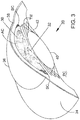
- FIG. 3 is a stylized perspective view illustrating the anatomy of an eye.
- FIG. 4 is a stylized perspective view showing Schlemm's canal and an iris of the eye shown in the previous figure.
- FIG. 5 is an enlarged cross-sectional view further illustrating Schlemm's canal SC shown in the previous figure.
- FIG. 6A is a perspective view showing a delivery system including an ocular implant and a cannula defining a passageway that is dimensioned to slidingly receive the ocular implant.
- FIG. 6B is an enlarged detail view further illustrating the ocular implant and the cannula 108 shown in FIG. 6A .
- FIG. 7 is a perspective view further illustrating delivery system 100 shown in FIG. 6 .
- FIG. 8 is an exploded view illustrating various elements of a delivery system in accordance with the detailed description.
- FIG. 8A is an end view of the rotating rack gear shown in FIG. 8 .
- FIG. 9 is an exploded perspective view further illustrating the delivery tool subassembly shown in the exploded perspective view of FIG. 8 .
- FIG. 10 is an exploded perspective view further illustrating the cannula subassembly shown in the exploded perspective view of FIG. 8 .
- FIG. 11 is a cross-sectional view showing an assembly including both the delivery tool subassembly and the cannula subassembly shown in the exploded perspective view of FIG. 8 .
- FIG. 12 is a perspective view of a cannula in accordance with the detailed description.
- FIG. 13 is a perspective view of an assembly including the cannula shown in FIG. 12 and an ocular implant that is resting in a passageway defined by the cannula.
- FIG. 14 is a stylized perspective view including the assembly shown in FIG. 13 .
- FIG. 15 is an enlarged perspective view showing a portion of the cannula shown in the assembly of FIG. 14 .
- FIG. 16 is an additional perspective view showing the ocular implant and the cannula shown in the previous FIG. 15 .
- FIG. 17 is an additional perspective view showing the ocular implant and the cannula shown in FIG. 16 .
- FIG. 18 is an additional perspective view showing the ocular implant and the cannula shown in FIGS. 16 and 17 .
- FIG. 19 is a perspective view of Schlemm's canal after the cannula shown in FIG. 18 has been withdrawn leaving an inlet portion of the ocular implant in the anterior chamber of the eye and the remainder of ocular implant in Schlemm's canal.
- FIG. 20A - FIG. 20H are a series of stylized plan views illustrating example methods in accordance with the detailed description and associated apparatus used while performing those methods.
- FIG. 21 is a perspective view showing a delivery tool subassembly 370 that may be part of a delivery system (e.g., the delivery system shown in FIG. 8 ).
- FIG. 22A is a stylized plan view further illustrating the delivery tool shown in FIG. 21 .
- FIG. 22B is an additional stylized plan view illustrating the cannula, ocular implant, and delivery tool shown in FIG. 22A .
- FIG. 23A is a perspective view showing another illustrative delivery system including an ocular implant and a cannula defining a passageway that is dimensioned to slidingly receive the ocular implant.
- FIG. 23B is an enlarged detail view further illustrating the ocular implant and the cannula shown in FIG. 23A .
- FIG. 24 is an enlarged perspective view further illustrating the delivery system shown in FIG. 23 and an eye.
- FIG. 25 is a perspective view further illustrating delivery system shown in FIG. 23 .
- FIG. 26 is an exploded view illustrating various elements of another illustrative delivery system in accordance with the detailed description.
- FIG. 26A is an end view of the rotating rack gear shown in FIG. 26 .
- FIG. 27 is a side view further illustrating the cannula shown in FIG. 23 .
- FIG. 27A is an additional side view illustrating the cannula shown in FIG. 23 .
- FIG. 28 is an enlarged detail view further illustrating the cannula shown in FIG. 23 .
- FIG. 29 is an enlarged perspective view further illustrating the distal portion of the cannula shown in FIG. 23 .
- numeric values are herein assumed to be modified by the term “about,” whether or not explicitly indicated.
- the term “about” generally refers to a range of numbers that one of skill in the art would consider equivalent to the recited value (i.e., having the same or substantially the same function or result). In many instances, the terms “about” may include numbers that are rounded to the nearest significant figure. Other uses of the term “about” (i.e., in a context other than numeric values) may be assumed to have their ordinary and customary definition(s), as understood from and consistent with the context of the specification, unless otherwise specified.
- references in the specification to “an embodiment”, “some embodiments”, “other embodiments”, etc. indicate that the embodiment(s) described may include a particular feature, structure, or characteristic, but every embodiment may not necessarily include the particular feature, structure, or characteristic. Moreover, such phrases are not necessarily referring to the same embodiment. Further, when a particular feature, structure, or characteristic is described in connection with an embodiment, it would be within the knowledge of one skilled in the art to affect such feature, structure, or characteristic in connection with other embodiments, whether or not explicitly described, unless clearly stated to the contrary.
- FIG. 1 is a stylized representation of a medical procedure in accordance with this detailed description.
- a physician is treating an eye 20 of a patient P.
- the physician is holding a hand piece of a delivery system 70 in his or her right hand RH.
- the physician's left hand (not shown) may be used to hold the handle H of a gonio lens 23 .
- some physicians may prefer holding the delivery system hand piece in the left hand and the gonio lens handle H in the right hand RH.
- the physician may view the interior of the anterior chamber using gonio lens 23 and a microscope 25 .
- Detail A of FIG. 1 is a stylized simulation of the image viewed by the physician.
- a distal portion of a cannula 72 is visible in Detail A.
- a shadow-like line indicates the location of Schlemm's canal SC which is lying under various tissues (e.g., the trabecular meshwork) that surround the anterior chamber.
- a distal opening 74 of cannula 72 is positioned near Schlemm's canal SC of eye 20 .
- Methods in accordance with this detailed description may include the step of advancing the distal end of cannula 72 through the cornea of eye 20 so that a distal portion of cannula 72 is disposed in the anterior chamber of the eye.
- Cannula 72 may then be used to access Schlemm's canal of the eye, for example, by piercing the wall of Schlemm's canal with the distal end of cannula 72 .
- Distal opening 74 of cannula 72 may be placed in fluid communication with a lumen defined by Schlemm's canal.
- the ocular implant may be advanced out of distal opening 74 and into Schlemm's canal. Insertion of the ocular implant into Schlemm's canal may facilitate the flow of aqueous humor out of the anterior chamber of the eye.
- FIG. 2 is an enlarged perspective view further illustrating delivery system 50 and eye 20 shown in the previous figure.
- cannula 56 of delivery system 50 is shown extending through a cornea 26 of eye 20 .
- a distal portion of cannula 56 is disposed inside the anterior chamber defined by cornea 26 of eye 20 .
- cannula 56 is configured so that a distal opening 58 of cannula 56 can be placed in fluid communication with Schlemm's canal.
- an ocular implant is disposed in a passageway defined by cannula 56 .
- Delivery system 50 includes a mechanism that is capable of advancing and retracting the ocular implant along the length of cannula 56 .
- the ocular implant may be placed in Schlemm's canal of eye 20 by advancing the ocular implant through the distal opening of cannula 56 while the distal opening is in fluid communication with Schlemm's canal.
- FIG. 3 is a stylized perspective view illustrating a portion of eye 20 discussed above.
- Eye 20 includes an iris 30 defining a pupil 32 .
- eye 20 is illustrated in a cross-sectional view created by a cutting plane passing through the center of pupil 32 .
- Eye 20 can be conceptualized as a fluid filled ball having two chambers.
- Sclera 34 of eye 20 surrounds a posterior chamber PC filled with a viscous fluid known as vitreous humor.
- Cornea 36 of eye 20 encloses an anterior chamber AC that is filled with a fluid known as aqueous humor.
- the cornea 36 meets the sclera 34 at a limbus 38 of eye 20 .
- a lens 40 of eye 20 is located between anterior chamber AC and posterior chamber PC. Lens 40 is held in place by a number of ciliary zonules 42 .
- the cornea and the lens can include no blood vessels. Accordingly, no blood flows through the cornea and the lens to provide nutrition to these tissues and to remove wastes from these tissues. Instead, these functions are performed by the aqueous humor.
- a continuous flow of aqueous humor through the eye provides nutrition to portions of the eye (e.g., the cornea and the lens) that have no blood vessels. This flow of aqueous humor also removes waste from these tissues.
- Aqueous humor is produced by an organ known as the ciliary body.
- the ciliary body includes epithelial cells that continuously secrete aqueous humor.
- a stream of aqueous humor flows out of the eye as new aqueous humor is secreted by the epithelial cells of the ciliary body. This excess aqueous humor enters the blood stream and is carried away by venous blood leaving the eye.
- Schlemm's canal SC is a tube-like structure that encircles iris 30 . Two laterally cut ends of Schlemm's canal SC are visible in the cross-sectional view of FIG. 3 .
- aqueous humor flows out of anterior chamber AC and into Schlemm's canal SC.
- Aqueous humor exits Schlemm's canal SC and flows into a number of collector channels.
- aqueous humor is absorbed into the venous blood stream and carried out of the eye.
- FIG. 4 is a stylized perspective view showing Schlemm's canal SC and iris 30 of eye 20 shown in the previous figure.
- Schlemm's canal SC is shown encircling iris 30 .
- Schlemm's canal SC may overhang iris 30 slightly.
- Iris 30 defines a pupil 32 .
- Schlemm's canal SC and iris 30 are shown in cross-section, with a cutting plane passing through the center of pupil 32 .
- Schlemm's canal SC is somewhat irregular, and can vary from patient to patient.
- the shape of Schlemm's canal SC may be conceptualized as a cylindrical-tube that has been partially flattened. With reference to FIG. 4 , it will be appreciated that Schlemm's canal SC has a first major side 50 , a second major side 52 , a first minor side 54 , and a second minor side 56 .
- Schlemm's canal SC forms a ring around iris 30 with pupil 32 disposed in the center of that ring.
- first major side 50 is on the outside of the ring formed by Schlemm's canal SC and second major side 52 is on the inside of the ring formed by Schlemm's canal SC.
- first major side 50 may be referred to as an outer major side of Schlemm's canal SC and second major side 52 may be referred to as an inner major side of Schlemm's canal SC.
- first major side 50 is further from pupil 32 than second major side 52 .
- the outer major wall of Schlemm's canal is supported by scleral tissue of the eye. Elevated pressure inside the eye of a patient suffering from glaucoma may cause the inside major wall of Schlemm's canal to be pressed against the outer major wall of the canal.
- FIG. 5 is an enlarged cross-sectional view further illustrating Schlemm's canal SC shown in the previous figure.
- Schlemm's canal SC comprises a wall W defining a lumen 58 .
- the shape of Schlemm's canal SC is somewhat irregular and can vary from patient to patient.
- the shape of Schlemm's canal SC may be conceptualized as a cylindrical-tube that has been partially flattened.
- the cross-sectional shape of lumen 58 may be compared to the shape of an ellipse.
- a major axis 60 and a minor axis 62 of lumen 58 are illustrated with dashed lines in FIG. 5 .
- the length of major axis 60 and minor axis 62 can vary from patient to patient.
- the length of minor axis 62 is between one and thirty micrometers in most patients.
- the length of major axis 60 is between one hundred and fifty micrometers and three hundred and fifty micrometers in most patients.
- Schlemm's canal SC comprises a first major side 50 , a second major side 52 , a first minor side 54 , and a second minor side 56 .
- first major side 50 is longer than both first minor side 54 and second minor side 56 .
- second major side 52 is longer than both first minor side 54 and second minor side 56 .
- FIG. 6A is a perspective view showing a delivery system 100 including an ocular implant 150 and a cannula 108 defining a passageway that is dimensioned to slidingly receive ocular implant 150 .
- Delivery system 100 may be used to advance ocular implant 150 into a target location in the eye of a patient. Examples of target locations that may be suitable in some applications include areas in and around Schlemm's canal, the trabecular meshwork, the suprachoroidal space, and the anterior chamber of the eye.
- FIG. 6B is an enlarged detail view further illustrating ocular implant 150 and cannula 108 of delivery system 100 .
- Delivery system 100 of FIG. 6A is capable of controlling the advancement and retraction of ocular implant 150 within cannula 108 .
- Ocular implant 150 may be placed in a target location (e.g., Schlemm's canal) by advancing the ocular implant through a distal opening 132 of cannula 108 while the distal opening is in fluid communication with Schlemm's canal.
- a target location e.g., Schlemm's canal
- ocular implant 150 has been advanced through distal opening 132 of cannula 108 for purposes of illustration.
- Delivery system 100 of FIG. 6A includes a housing 102 , a sleeve 104 , and an end cap 110 .
- a tracking wheel 106 extends through a wall of housing 102 in FIG. 6A .
- Tracking wheel 106 is part of a mechanism that is capable of advancing and retracting a delivery tool 152 of delivery system 100 .
- the delivery tool 152 extends through a distal opening of cannula 108 of FIG. 6B .
- Rotating the tracking wheel will cause delivery tool 152 to move in an axial direction along a passageway defined by cannula 108 .
- the axial direction may be in a distal direction D or a proximal direction P.
- housing 102 is configured to be gripped with one hand while providing control over the axial advancement and retraction of ocular implant via tracking wheel 106 .
- the housing of delivery system 100 results in an advantageous ergonomic relationship of the fingers relative to the hand. This design provides a configuration that will allow a user, such as a physician, to stabilize the device using part of the hand, while leaving the middle or index finger free move independently from the remainder of the hand. The middle or index finger is free to move independently to rotate the wheel for advancing and/or retract the ocular implant.
- FIG. 6B is an enlarged detail view further illustrating ocular implant 150 and a cannula 108 of delivery system 100 .
- Cannula 108 comprises a generally tubular member 198 having proximal portion 140 , a distal end 134 , and a distal portion 144 extending between distal end 134 and proximal portion 140 .
- distal portion 144 is curved.
- distal portion 144 is dimensioned and configured to be received in the anterior chamber of the eye.
- FIG. 6B shows delivery tool 152 of delivery system 100 extending through distal opening 132 of cannula 108 .
- Delivery tool 152 includes an interlocking portion 160 that is configured to form a connection with a complementary interlocking portion 162 of ocular implant 150 , as explained in more detail below.
- rotating the tracking wheel will cause delivery tool 152 and ocular implant 150 to move along a path defined by cannula 108 .
- Cannula 108 is sized and configured so that the distal end of cannula 108 can be advanced through the trabecular meshwork of the eye and into Schlemm's canal. Positioning cannula 108 in this way places distal opening 132 in fluid communication with Schlemm's canal.
- Ocular implant 150 may be placed in Schlemm's canal by advancing the ocular implant through distal opening 132 of cannula 108 while the distal opening is in fluid communication with Schlemm's canal.
- the distal portion of the cannula may include a cutting portion configured to cut through the trabecular meshwork and the wall of Schlemm's canal, such as by providing distal end 134 with a sharp edge adapted to cut through such tissue.
- FIG. 7 is a perspective view further illustrating delivery system 100 shown in the previous figure.
- Delivery system 100 includes a delivery tool subassembly 170 and a cannula subassembly 180 .
- Delivery tool subassembly 170 includes rotating rack gear 120 and a delivery tool (not shown).
- the delivery tool extends into a passageway defined by a cannula 108 .
- Cannula 108 can be seen extending beyond sleeve 104 in FIG. 7 .
- Cannula subassembly 180 includes cannula 108 , a hub 172 , and an extension tube (not shown).
- the extension tube of cannula subassembly 180 is disposed inside a lumen defined by rotating rack gear 120 .
- Delivery system 100 includes a mechanism 166 that controls the movement of delivery tool subassembly 170 .
- Mechanism 166 includes a number of components that are located inside housing 102 , including tracking wheel 106 , an idler gear 122 , and the rotating rack gear 120 .
- tracking wheel 106 and idler gear 122 are both rotatably supported by housing 102 .
- Gear teeth on tracking wheel 106 engage gear teeth on idler gear 122 , which in turn engage gear teeth on the rotating rack gear 120 .
- Rotating tracking wheel 106 in a counter clockwise direction CCW causes idler gear 122 to rotate in a clockwise direction CW, which in turn causes the rotating rack gear 120 to move in a distal direction D.
- Rotating tracking wheel 106 in a clockwise direction CW causes idler gear 122 to rotate in a counter clockwise direction CCW, which in turn causes the rotating rack gear 120 to move in a proximal direction P.
- the idler gear may be eliminated from the device, which would cause counter-clockwise movement of the tracking wheel to move the rack gear proximally.
- a sleeve 104 is fixed to cannula subassembly 180 .
- Sleeve 104 may be rotated by the user to change the orientation of cannula 108 with respect to housing 102 .
- the sleeve 104 may include gripping features, such as grooves (as shown), a rubber coating, or other frictional surfaces to facilitate this use.
- gripping features such as grooves (as shown), a rubber coating, or other frictional surfaces to facilitate this use.
- correct alignment between the cannula and iris is advantageous to ensure that the core tube and/or ocular implant is advanced at the correct trajectory relative to Schlemm's canal or other anatomy in the eye into which the ocular implant is to be implanted.
- the device is configured in a manner that keeps the ocular implant aligned within the device during rotation.
- Selected groups of components are keyed together to ensure that they rotate as a single body while simultaneously allowing axial movement of the ocular implant.
- cannula subassembly 180 and delivery tool subassembly 170 rotate in unison with sleeve 104 relative to housing 102 .
- rotating rack gear 120 is configured to rotate with sleeve 104 while maintaining the ability to move axially in the distal and proximal directions before, during, and after rotation. As the rotating rack gear 120 moves distally and/or proximally, it causes corresponding movement of the delivery tool relative to cannula 108 . This movement is transferred to ocular implant 150 when delivery tool 152 is coupled to ocular implant 150 . Delivery tool subassembly 170 and cannula subassembly 180 engage one another in a keyed arrangement, as described in more detail below.
- This keyed arrangement causes delivery tool subassembly 170 and cannula subassembly 180 to maintain a constant rotational orientation relative to each other while, at the same time, allowing delivery tool subassembly 170 to translate in a distal direction D and a proximal direction P relative to cannula subassembly 180 .
- FIG. 8 is an exploded view illustrating various elements of delivery system 100 .
- Cannula subassembly 180 includes a hub 172 and an extension tube 174 that are both fixed to cannula 108 .
- Extension tube 174 includes a shaped portion 175 that is dimensioned and shaped to fit within a shaped through hole 177 (shown in FIGS. 8A and 11 ) by rotating rack gear 120 .
- This keyed arrangement causes delivery tool subassembly 170 and cannula subassembly 180 to maintain a constant rotational orientation relative to each other while, at the same time, allowing delivery tool subassembly 170 to translate in a distal direction D and a proximal direction P relative to cannula subassembly 180 .
- delivery tool 152 is formed from shape memory material (such as, e.g., nitinol), and at least a portion of delivery tool 152 assumes a curved at-rest shape when no external forces are acting on it. Delivery tool 152 can be urged to assume a straightened shape, for example, by inserting delivery tool 152 through a straight portion of the passageway defined by cannula 108 . When the delivery tool is confined, such as within cannula 108 , the interlocking portion can engage the complementary interlocking portion to join the delivery tool and ocular implant together, and allow the delivery tool and ocular implant to move together through the cannula 108 , as described in more detail below.
- shape memory material such as, e.g., nitinol
- Delivery system 100 also includes an O-ring 126 disposed between sleeve 104 and housing 102 .
- O-ring 126 can provide friction and/or resistance between sleeve 104 and housing 102 . This friction and/or resistance may be useful, for example, to hold the sleeve 104 in a desired orientation.
- a noseplug 105 snaps into the distal end of the delivery system.
- FIG. 9 is an exploded perspective view of delivery tool subassembly 170 shown in the previous figure.
- Delivery tool subassembly 170 comprises a delivery tool 152 , a rotating rack gear 120 , and a spacer 176 .
- Delivery tool 152 includes a shaped proximal portion 156 , a curved distal portion 153 , a distal cannula engagement surface 161 and a reduced diameter portion 163 proximal to the distal cannula engagement surface 161 .
- Spacer 176 is interposed between rotating rack gear 120 and shaped proximal portion 156 of delivery tool 152 to hold delivery tool 152 and rotating rack gear 120 in a generally co-axial arrangement when delivery tool subassembly 170 is in an assembled state, as shown in FIG. 11 .
- Distal cannula engagement surface 161 is adapted to slide along an inside surface of the cannula wall while the delivery tool 152 is engaged to ocular implant 150 .
- Curved distal portion 153 of delivery tool 152 has an at rest curve that is greater (i.e., has a smaller radius of curvature) than the curved portion 144 of cannula 108 .
- FIG. 10 is an exploded perspective view of cannula subassembly 180 .
- Cannula subassembly 180 comprises cannula 108 , extension tube 174 and hub 172 .
- cannula 108 defines a passageway 138 that is dimensioned to slidingly receive an ocular implant and the delivery tool shown in the previous figure.
- extension tube 174 of cannula subassembly 180 may be received inside a lumen defined by the rotating rack gear shown in the previous figure.
- Extension tube 174 includes a shaped portion 175 that is dimensioned and shaped to fit within a shaped through hole defined by rotating rack gear 120 , as shown below in FIG. 11 .
- This keyed arrangement causes delivery tool subassembly 170 and cannula subassembly 180 to maintain a constant rotational orientation relative to each other while, at the same time, allowing delivery tool subassembly 170 to translate in a distal direction D and a proximal direction P relative to cannula subassembly 180 .
- FIG. 11 is a cross-sectional view showing an assembly including delivery tool subassembly 170 and cannula subassembly 180 discussed above.
- Delivery tool subassembly 170 includes a delivery tool 152 , a rotating rack gear 120 and a spacer 176 .
- a shaped portion 156 of delivery tool 152 can be seen extending into a slot 123 extending from a central portion 181 through hole 177 formed in rotating rack gear 120 .
- FIG. 8A shows an end view of rotating rack gear 120 and through hole 177 .
- an interlocking portion 160 of delivery tool 152 is disposed in angular alignment with shaped portion 156 .
- Spacer 176 is interposed between rotating rack gear 120 and delivery tool 152 .
- spacer 176 is shaped and dimensioned to hold delivery tool 152 and rotating rack gear in a generally co-axial arrangement. This arrangement creates an advantageous oriented relationship of interlocking portion 160 with respect to the distal opening 132 of cannula 108 and ensures that interlocking portion 160 is unimpeded and readily disengages itself from the implant when it exits and flexes through distal opening 132 .
- spacer 176 and rotating rack gear 120 are fixed to each other at a weld joint 178 .
- Weld joint 178 may be formed, for example, using a laser welding process.
- Cannula subassembly 180 includes cannula 108 , a hub 172 , and an extension tube 174 .
- Extension tube 174 is disposed about cannula 108 .
- Extension tube 174 and cannula 108 may be fixed to one another, for example, using a laser spot welding process.
- Hub 172 is fixed to an outer surface portion of extension tube 174 in the embodiment of FIG. 11 at a weld joint 179 .
- Weld joint 179 may be formed, for example, using a laser welding process.
- extension tube 174 of cannula subassembly 180 can be seen extending into a shaped through-hole defined by rotating rack gear 120 of delivery tool assembly 170 .
- delivery tool 152 can be seen extending into a passageway 138 defined by a cannula 108 of cannula subassembly 180 .
- Passageway 138 defined by cannula 108 is sized to slidably enclose delivery tool 152 and an ocular implant that is coupled to delivery tool 152 .
- Delivery tool 152 is configured to form a connection with the ocular implant, so that distal movement of the delivery tool can cause distal movement of the ocular implant within cannula 108 .
- Delivery tool 152 may be used to advance the ocular implant through a distal opening 132 of cannula 108 in order to deliver the ocular implant into the eye.
- 11 may be rotated by the user to change the orientation of the curved portion of cannula 108 with respect to the housing of the delivery system.
- the keyed relationship between delivery tool subassembly 170 and cannula subassembly 180 assures that the rotational orientation between cannula 108 and the ocular implant/delivery tool stays constant while at the same time, allowing ocular implant/delivery tool to translate in a distal direction D and a proximal direction P relative to cannula 108 .
- FIG. 12 is a perspective view of a cannula 108 in accordance with the present detailed description.
- Cannula 108 of FIG. 12 comprises a generally tubular member 198 having a central axis 196 .
- Generally tubular member 198 of FIG. 12 comprises a proximal portion 140 , a distal end 134 , and a distal portion 144 extending between distal end 134 and proximal portion 140 .
- a distal opening surface 142 surrounds a distal opening 132 extending through the distal end 134 and through a side wall of cannula 108 .
- a beveled edge 165 is disposed at the distal end of distal opening surface 142 , extending from the distal end 134 to a proximal extent 167 of beveled edge 165 .
- Tubular member 198 defines distal opening 132 , a proximal opening 136 , and a passageway 138 extending between proximal opening 136 and distal opening 132 .
- proximal portion 140 of cannula 108 is substantially straight, distal portion 144 of cannula 108 is curved, and central axis 196 defines a curvature plane 148 .
- Curvature plane 148 may be referred to as a plane of curvature. Curvature plane 148 divides cannula 108 into a first portion PA and a second portion PB. In the embodiment of FIG. 12 , second portion PB is substantially a mirror image of first portion PA.
- distal portion 144 is shown extending between distal end 134 and proximal portion 140 with no intervening elements. In the embodiment of FIG. 12 , distal portion 144 is curved along its entire length.
- a method in accordance with this detailed description may include the step of advancing the distal end 134 of cannula 108 through the cornea of a human eye so that distal end 134 is disposed in the anterior chamber of the eye.
- Cannula 108 may then be used to access Schlemm's canal of the eye, for example, by piercing the wall of Schlemm's canal with the distal end 134 of cannula 108 .
- the beveled edge 165 may be inserted into Schlemm's canal to place at least part of distal opening 132 of cannula 108 in communication with Schlemm's canal, as discussed in more detail below.
- the ocular implant may be advanced out of a distal port of the cannula and into Schlemm's canal.
- distal portion 144 of cannula 108 defines a trough 154 .
- trough 154 is configured to receive the entire external cross section of an ocular implant as the ocular implant is being advanced into Schlemm's canal.
- trough 154 may have a depth dimension that is deeper than a width of the ocular implant. This cannula configuration advantageously prevents the ocular implant from intersecting the layers of the trabecular meshwork as the ocular implant is advanced into Schlemm's canal.
- Trough 154 may also be configured to allow the proximal portion of the ocular implant to be released from the delivery tool, as discussed below.
- FIG. 13 is a perspective view of an assembly including cannula 108 shown in the previous figure.
- cannula 108 is cross-sectionally illustrated in FIG. 13 .
- an ocular implant 150 can be seen resting in a passageway 138 defined by cannula 108 .
- distal portion 144 of cannula 108 is curved so that central axis 196 of cannula 108 defines a curvature plane 148 .
- curvature plane 148 divides cannula 108 into a first portion and a second portion PB. Only second portion PB of cannula 108 is shown in the illustrative embodiment of FIG. 13 .
- FIG. 14 is a stylized perspective view including the assembly shown in the previous figure.
- a distal portion of cannula 108 is shown extending through the wall of Schlemm's canal SC.
- the distal tip of cannula 108 may include a sharp portion configured for cutting and/or piercing the trabecular meshwork and the wall of Schlemm's canal so that the passageway defined by the cannula can be placed in fluid communication with the lumen defined by Schlemm's canal.
- ocular implant 150 With the passageway of the cannula placed in fluid communication with the lumen of Schlemm's canal, ocular implant 150 can be advanced out of the distal opening of the cannula and into Schlemm's canal.
- a distal portion of ocular implant 150 can be seen through distal opening 132 of cannula 108 .
- a hypothetical window W is cut through the wall of cannula 108 in FIG. 14 .
- An interlocking portion 160 of a delivery tool 152 and a complementary interlocking portion 162 of ocular implant 150 are visible through window W.
- interlocking portion 160 of delivery tool 152 and complementary interlocking portion 162 of ocular implant 150 are engaging each other so that a proximal end 149 of ocular implant 150 is proximal to the distal end 151 of delivery tool 152 .
- Surface 161 of delivery tool 152 rests against the wall of cannula 108 to prevent interlocking portion 160 of delivery tool 152 and complementary interlocking portion 162 of ocular implant 150 from disengaging one another.
- delivery tool 152 and ocular implant 150 move together as the delivery tool is advanced and retracted relative to cannula 108 by the delivery system mechanism.
- FIG. 15 is an enlarged perspective view showing a portion of cannula 108 shown in the previous figure.
- cannula 108 is curved to achieve substantially tangential entry into Schlemm's canal SC.
- cannula 108 is contacting an outer major wall of Schlemm's canal SC at a point of tangency PT.
- a curved distal portion of cannula 108 is dimensioned to be disposed within the anterior chamber of the eye.
- the distal tip 134 and beveled edge of the cannula 108 have been inserted into Schlemm's canal up to the proximal extent 167 of beveled edge 165 .
- ocular implant 150 can be seen extending into trough 154 .
- the ocular implant has a radius of curvature that is larger than the radius of curvature of the cannula. This arrangement ensures that the ocular implant will track along trough 154 as the ocular implant is urged in a distal direction by delivery system 100 .
- FIG. 16 is an additional perspective view showing ocular implant 150 and cannula 108 shown in the previous figure.
- ocular implant 150 has been advanced in a distal direction D while cannula 108 has remained stationary so that a distal portion of ocular implant 150 is disposed inside Schlemm's canal SC.
- Trough 154 opens into an elongate opening 132 defined by edge 142 at the distal portion of cannula 108 .
- the elongate opening defined by the cannula provides direct visualization of the ocular implant as it is advanced into Schlemm's canal.
- a configuration allowing direct visualization of the ocular implant has a number of clinical advantages.
- ocular implant 150 tracks along trough 154 as it is advanced distally along cannula 108 .
- the trough opening allows the physician to monitor the progress of the implant by viewing the implant structures as they advance through the trough prior to entering Schlemm's canal.
- the trough opening also allows the physician to identify the position of the proximal end of the ocular implant with respect to the incision made by the cannula to access Schlemm's canal.
- FIG. 17 is an additional stylized perspective view showing ocular implant 150 and cannula 108 .
- the interlocking portions 160 and 162 of the delivery tool 152 and ocular implant 150 can be seen entering the distal opening 132 defined by cannula 108 .
- ocular implant 150 has been advanced in a distal direction D (relative to the embodiment shown in the previous figure) so that more of ocular implant 150 is disposed inside Schlemm's canal SC.
- Surface 161 opposite interlocking portion 160 of delivery tool 152 still rests against the inner wall of cannula 108 to keep the delivery tool interlocked with ocular implant 150 .
- FIG. 18 is an additional stylized perspective view showing ocular implant 150 and cannula 108 .
- the ocular implant 150 and delivery tool 152 have advanced further distally so that delivery tool surface 161 and part of the reduced diameter portion 163 have now passed into opening 132 , thereby permitting the delivery tool curved portion 153 to move toward its curved at-rest shape so that the delivery tool engagement surface 160 disengages and moves away from its complementary engagement surface 162 on the ocular implant 150 .
- the delivery tool may be colored to provide visual differentiation from the implant.
- cannula 108 and delivery tool 152 can be withdrawn from Schlemm's canal SC leaving the ocular implant 150 in the fully deployed position shown in FIG. 18 .
- the delivery tool and the cannula may be removed from the eye, leaving at least a distal portion of the ocular implant in Schlemm's canal.
- FIG. 19 is a perspective view of Schlemm's canal SC after the cannula (seen in the previous figure) has been withdrawn leaving an inlet portion of ocular implant 150 in the anterior chamber of the eye and the remainder of ocular implant 150 in Schlemm's canal.
- the presence of ocular implant 150 in Schlemm's canal may facilitate the flow of aqueous humor out of the anterior chamber. This flow may include axial flow along Schlemm's canal, flow from the anterior chamber into Schlemm's canal, and flow leaving Schlemm's canal via outlets communicating with Schlemm's canal.
- ocular implant 150 When in place within the eye, ocular implant 150 will support the trabecular meshwork and Schlemm's canal tissue and will provide for improved communication between the anterior chamber and Schlemm's canal (via the trabecular meshwork) and between pockets or compartments along Schlemm's canal.
- FIG. 20A - FIG. 20H are a series of stylized plan views illustrating example methods in accordance with this detailed description and associated apparatus used while performing those methods.
- a distal portion of cannula 108 is shown extending through the wall of Schlemm's canal SC.
- cannula 108 includes a sharp portion at its distal end 134 configured for cutting and/or piercing the trabecular meshwork and the wall of Schlemm's canal SC.
- FIG. 20A is a sharp portion at its distal end 134 configured for cutting and/or piercing the trabecular meshwork and the wall of Schlemm's canal SC.
- cannula 108 has been advanced through the trabecular meshwork and the wall of Schlemm's canal SC and a passageway defined by cannula 108 has been placed in fluid communication with the lumen defined by Schlemm's canal SC.
- FIG. 20B is an additional stylized plan view showing cannula 108 shown in the previous figure.
- an ocular implant 150 has been advanced out of a distal opening of cannula 108 and into Schlemm's canal SC.
- a distal portion of ocular implant 150 is shown residing in a lumen defined by Schlemm's canal.
- FIG. 20C is an additional stylized plan view showing ocular implant 150 and cannula 108 .
- an interlocking portion 160 of delivery tool 152 and complementary interlocking portion 162 of ocular implant 150 are both disposed near a trough portion of cannula 108 .
- Ocular implant 150 has been advanced in a distal direction D (relative to the embodiment shown in the previous figure) so that more of ocular implant 150 is disposed inside Schlemm's canal SC.
- ocular implant is shown residing in a fully deployed position.
- interlocking portion 160 of delivery tool 152 has disengaged from complementary interlocking portion 162 of ocular implant 150 .
- distal opening 132 defined by cannula 108 is shaped and dimensioned so as to allow interlocking portion 160 of delivery tool 152 to extend therethrough when ocular implant 150 reaches the fully deployed position shown in FIG. 20C .
- a distal portion of delivery tool 152 is free to flex radially inward toward a curved, at-rest shape extending through distal opening 132 when ocular implant 150 reaches the fully deployed position shown in FIG. 20C to disengage from the ocular implant.
- FIG. 20D is a plan view of Schlemm's canal SC after cannula 108 has been moved away from ocular implant 150 .
- a physician may visually inspect the present location of the ocular implant to determine whether that location is acceptable. If the physician determines that the present location is unacceptable, the physician may use the systems and methods described herein to recapture and reposition the ocular implant.
- the figures described below illustrate exemplary methods and apparatus for recapturing and repositioning the ocular implant.
- cannula 108 has been positioned so that the complementary interlocking portion 162 of ocular implant 150 is disposed between cannula 108 and the interlocking portion 160 of delivery tool 152 . Further distal movement of cannula 108 will cause delivery tool surface 161 to re-engage with the inner wall of cannula 108 , thereby moving the interlocking portion 160 of the delivery tool into re-engagement with the ocular implant. The delivery tool and ocular implant can thereafter be moved proximally, possibly together with the cannula, to reposition the implant for subsequent redeployment.
- FIG. 20F is an additional stylized plan view showing ocular implant 150 and cannula 108 shown in the previous figure.
- delivery tool 152 and ocular implant 150 have been moved in a proximal direction P so that a portion of ocular implant 150 has been withdrawn from Schlemm's canal SC.
- the complementary interlocking portion of ocular implant 150 and the interlocking portion of delivery tool 152 have both been drawn into the passageway defined by cannula 108 .
- the side wall of cannula 108 is holding the distal portion of delivery tool 152 in a deformed shape with the interlocking portion of delivery tool 152 engaging the complementary interlocking portion of ocular implant 150 .
- FIG. 20G is an additional stylized plan view showing ocular implant 150 and cannula 108 shown in the previous figure.
- ocular implant 150 has been advanced out of a distal opening of cannula 108 and into Schlemm's canal SC.
- a distal part of ocular implant 150 is shown residing in a lumen defined by Schlemm's canal.
- interlocking portion 160 of delivery tool 152 and complementary interlocking portion 162 of ocular implant 150 are both once again located near a trough portion of cannula 108 .
- ocular implant is shown residing in a second fully deployed position.
- the delivery tool 152 has once again disengaged from ocular implant 150 by permitting interlocking portion 160 of delivery tool 152 to move away from complementary interlocking portion 162 of ocular implant 150
- FIG. 20H is a stylized plan view showing ocular implant 150 and Schlemm's canal SC after the cannula (seen in the previous figure) has been withdrawn leaving an inlet portion of ocular implant 150 in the anterior chamber of the eye and the remainder of ocular implant 150 in Schlemm's canal.
- ocular implant 150 When in place within the eye, ocular implant 150 will support the trabecular meshwork and Schlemm's canal tissue and will provide for improved communication between the anterior chamber and Schlemm's canal (via the trabecular meshwork) and between pockets or compartments along Schlemm's canal. Accordingly, the presence of ocular implant 150 in Schlemm's canal will facilitate the flow of aqueous humor out of the anterior chamber.
- An exemplary method in accordance with the present detailed description may include the step of advancing a distal end of a cannula through a cornea of the eye so that a distal portion of the cannula is disposed in the anterior chamber of the eye.
- the cannula may be used to access Schlemm's canal, for example, by cutting and/or piercing the wall of Schlemm's canal with a distal portion of the cannula.
- a distal opening of the cannula may be placed in fluid communication with Schlemm's canal.
- the distal end of the ocular implant may be advanced through the distal opening of the cannula and into Schlemm's canal.
- Recapturing and redelivering the ocular implant may include the steps of forming a second connection between the delivery tool and the ocular implant and moving the delivery tool and the ocular implant in a proximal direction so that at least a portion of the ocular implant is withdrawn from Schlemm's canal.
- a distal part of the ocular implant may be advanced into Schlemm's canal while the ocular implant is coupled to the delivery tool at the second connection.
- the second connection may be selectively broken to release the ocular implant from the delivery system while the distal part of the ocular implant is disposed in Schlemm's canal.
- FIG. 21 is a perspective view showing a delivery tool subassembly 370 that may be part of a delivery system (e.g., delivery system 100 shown in FIG. 8 ).
- Delivery tool subassembly 370 of FIG. 21 comprises a rotating rack gear 320 that is fixed to a delivery tool 352 .
- Delivery tool 352 includes an interlocking portion 360 and a curved distal portion 353 . Curved distal portion 353 of delivery tool 352 is biased to assume the curved at-rest shape shown in FIG. 21 when no external forces are acting on it.
- Curved distal portion 353 of delivery tool 352 may be urged to assume a straightened shape, for example, when it is disposed in a straight portion of a passageway defined by a cannula.
- Optional cut-outs 351 may be formed in the wall of delivery tool 352 to reduce friction during tool advancement by reducing the bending force.
- the cannula wall may also hold interlocking portion 360 of delivery tool 352 into engagement with a complementary interlocking portion of an ocular implant to form a mechanically interlocking connection.
- FIG. 22A is a stylized plan view showing delivery tool 352 shown in the previous figure.
- delivery tool 352 is extending into a passageway 338 defined by a cannula 308 .
- a distal portion of cannula 308 defines a trough 354 that communicates with the passageway 338 defined by the wall of cannula 308 .
- Trough 354 opens out the distal end of cannula 308 .
- Trough 354 also opens into an elongate opening 332 defined by the edge 342 of the cannula wall.
- cannula 308 is illustrated in partial cross section. Interlocking portion 360 of delivery tool 352 and a complementary interlocking portion 362 of an ocular implant 350 are visible in FIG. 22A .
- interlocking portion 360 of delivery tool 352 and complementary interlocking portion 362 of ocular implant 350 are engaging each other to form a mechanically interlocking connection such that the implant's interlocking portion 362 is proximal to the delivery tool's interlocking portion 360 .
- the delivery tool 352 and ocular implant 350 may be selectively disengaged when interlocking portion 360 of delivery tool 352 is allowed to move away from and disengage complementary interlocking portion 362 of ocular implant 350 .
- the wall of cannula 308 is preventing interlocking portion 360 of delivery tool 352 from moving away from and disengaging complementary interlocking portion 362 of ocular implant 350 .
- a surface 363 of delivery tool 352 can be seen contacting the wall of cannula 308 at a point S in FIG. 22 .
- interlocking portion 360 of delivery tool 352 is shown disposed within cannula passageway 338 at a location proximal of trough 354 and distal opening 332 .
- opening 332 is dimensioned and positioned such that, when the ocular implant reaches a predefined location along the passageway, the distal portion of delivery tool 352 will be free to move toward a curved at-rest shape.
- the interlocking portion of the delivery tool moves away from and disengages the complementary interlocking portion of the ocular implant.
- delivery tool 352 and ocular implant 350 may be selectively disengaged as delivery tool 352 is moved distally along the passageway defined by the cannula from a starting location proximal of opening 332 .
- FIG. 22B is an additional stylized plan view illustrating cannula 308 , ocular implant 350 , and delivery tool 352 shown in the previous figure.
- delivery tool 352 has been advanced in a distal direction D so that delivery tool 352 is extending through opening 332 and ocular implant 350 is outside of cannula passageway 338 .
- interlocking portion 360 has moved away from complementary interlocking portion 362 and ocular implant 350 and delivery tool 352 have disengaged.
- FIG. 23A is a perspective view showing another illustrative delivery system 400 that may be used to advance ocular implant 450 into a target location in the eye of a patient through an incision location created for another procedure, such as, but not limited to cataract surgery.
- the delivery system 400 may include an ocular implant 450 and a cannula 408 defining a passageway that is dimensioned to slidingly receive ocular implant 450 .
- FIG. 23B is an enlarged detail view further illustrating ocular implant 450 and cannula 408 of delivery system 400 .
- Delivery system 400 of FIG. 23A is capable of controlling the advancement and retraction of ocular implant 450 within cannula 408 .
- Ocular implant 450 may be placed in a target location (e.g., Schlemm's canal) by advancing the ocular implant 450 through a distal opening 432 of cannula 408 while the distal opening is in fluid communication with Schlemm's canal.
- a target location e.g., Schlemm's canal
- ocular implant 450 has been advanced through distal opening 432 of cannula 408 for purposes of illustration.
- Delivery system 400 of FIG. 23A includes a housing 402 , a sleeve 404 , and an end cap 410 .
- a tracking wheel 406 extends through a wall of housing 402 in FIG. 23A .
- Tracking wheel 406 is part of a mechanism that is capable of advancing and retracting a delivery tool 452 of delivery system 400 .
- the delivery tool 452 is slidably disposed within cannula 408 and configured to extend through a distal opening of cannula 408 . Rotating the tracking wheel will cause delivery tool 452 to move in an axial direction along a passageway defined by cannula 408 .
- the axial direction may be in a distal direction D or a proximal direction P.
- Delivery tool 452 may be similar in form and function to delivery tool 152 .
- housing 402 is configured to be gripped with one hand while providing control over the axial advancement and retraction of ocular implant via tracking wheel 406 .
- the features of housing 402 result in an advantageous ergonomic relationship of the fingers relative to the hand.
- This design provides a configuration that will allow a user, such as a physician, to stabilize the device using part of the hand, while leaving the middle or index finger free move independently from the remainder of the hand.
- the middle or index finger is free to move independently to rotate the wheel for advancing and/or retract the ocular implant.
- FIG. 23B is an enlarged detail view further illustrating ocular implant 450 and a cannula 408 of delivery system 400 .
- Cannula 408 comprises a generally tubular member 498 having proximal portion 440 , an intermediate portion 445 , a distal portion 444 , and a distal end 434 .
- the intermediate portion 445 may extend distally from a first point 443 distal to the proximal end 441 to a second point 447 proximal to the distal end 434 .
- the distal portion 444 may extend between distally from the second point 447 to distal end 434 of cannula 408 (shown in FIG. 27 ).
- FIG. 27 In the embodiment of FIG.
- both distal portion 444 and intermediate portion 445 may be curved.
- distal portion 444 may have a smaller radius of curvature, and thus a higher curvature, than the intermediate portion 445 , although this is not required.
- distal portion 444 and intermediate portion 445 may be dimensioned and configured to be received in the anterior chamber of the eye.
- the ocular implant 450 may be desirable to place during another ocular procedure, such as, but not limited to cataract surgery. It is contemplated that the optimal position for an incision for cataract surgery may not be the same as the optimal position of an incision for solely placing an ocular implant, such as implant 450 , into Schlemm's canal. With previous ocular implant delivery system designs, in order to allow for substantially tangential entry of the cannula into Schlemm's canal two separate incisions may be required when the implant is placed in combination with another ocular procedure. The curved configuration of both the distal portion 444 may be configured to allow for substantially tangential entry of the cannula 408 into Schlemm's canal.
- the curved configuration of the intermediate portion 445 may allow the cannula 408 to be advanced through typical incisions associated with and/or optimized for cataract surgery, such as, but not limited to, a sclerocorneal tunnel incision, while still allowing for substantially tangential entry of the cannula 408 into Schlemm's canal. This may allow for two or more ocular procedures to be performed using a single incision. It is further contemplated that performing multiple procedures through a single incision may reduce patient discomfort and recovery time.
- FIG. 23B shows delivery tool 452 of delivery system 400 extending through distal opening 432 of cannula 408 .
- Delivery tool 452 includes an interlocking portion 460 that is configured to form a connection with a complementary interlocking portion 462 of ocular implant 450 , as explained in more detail below.
- rotating the tracking wheel will cause delivery tool 452 and ocular implant 450 to move along a path defined by cannula 408 .
- Cannula 408 is sized and configured so that the distal end of cannula 408 can be advanced through the trabecular meshwork of the eye and into Schlemm's canal. Positioning cannula 408 in this way places distal opening 432 in fluid communication with Schlemm's canal.
- Ocular implant 450 may be placed in Schlemm's canal by advancing the ocular implant through distal opening 432 of cannula 408 while the distal opening is in fluid communication with Schlemm's canal.
- the distal portion of the cannula 408 may include a cutting portion configured to cut through the trabecular meshwork and the wall of Schlemm's canal, such as by providing distal end 434 with a sharp edge adapted to cut through such tissue.
- FIG. 24 is an enlarged perspective view further illustrating delivery system 400 shown in the previous figure and an eye 401 .
- cannula 408 of delivery system 400 is shown extending through a cornea 403 of eye 401 .
- a distal portion of cannula 408 is disposed inside the anterior chamber defined by cornea 403 of eye 401 .
- cannula 408 is configured so that a distal opening 432 of cannula 408 can be placed in fluid communication with Schlemm's canal.
- distal portion 444 and intermediate portion 445 of cannula 408 may be dimensioned and configured such that cannula 408 may be advanced through an incision 407 created for another optical surgical procedure.
- an ocular implant is disposed in a passageway defined by cannula 408 .
- Delivery system 400 includes a mechanism that is capable of advancing and retracting the ocular implant along the length of cannula 408 .
- the ocular implant may be placed in Schlemm's canal of eye 401 by advancing the ocular implant through the distal opening of cannula 408 while the distal opening is in fluid communication with Schlemm's canal.
- FIG. 25 is a perspective view further illustrating delivery system 400 shown in the previous figure.
- Delivery system 400 includes a delivery tool subassembly 470 and a cannula subassembly 480 .
- Delivery tool subassembly 470 includes rotating rack gear 420 and a delivery tool (not shown).
- the delivery tool extends into a passageway defined by a cannula 408 .
- Cannula 408 can be seen extending beyond sleeve 404 in FIG. 25 .
- Cannula subassembly 480 includes cannula 408 , a hub 472 , and an extension tube (not shown).
- the extension tube of cannula subassembly 480 is disposed inside a lumen defined by rotating rack gear 420 .
- Delivery system 400 includes a mechanism 466 that controls the movement of delivery tool subassembly 470 .
- Mechanism 466 includes a number of components that are located inside housing 402 , including tracking wheel 406 , an idler gear 422 , and the rotating rack gear 420 .
- tracking wheel 406 and idler gear 422 are both rotatably supported by housing 402 .
- Gear teeth on tracking wheel 406 engage gear teeth on idler gear 422 , which in turn engage gear teeth on the rotating rack gear 420 .
- Rotating tracking wheel 406 in a counter clockwise direction CCW causes idler gear 422 to rotate in a clockwise direction CW, which in turn causes the rotating rack gear 420 to move in a distal direction D.
- Rotating tracking wheel 406 in a clockwise direction CW causes idler gear 422 to rotate in a counter clockwise direction CCW, which in turn causes the rotating rack gear 420 to move in a proximal direction P.
- the idler gear 422 may be eliminated from the device, which would cause counter-clockwise movement of the tracking wheel to move the rack gear proximally.
- a sleeve 404 is fixed to cannula subassembly 480 .
- Sleeve 404 may be rotated by the user to change the orientation of cannula 408 with respect to housing 402 .
- the sleeve 404 may include gripping features, such as grooves (as shown), a rubber coating, or other frictional surfaces to facilitate this use.
- gripping features such as grooves (as shown), a rubber coating, or other frictional surfaces to facilitate this use.
- correct alignment between the cannula and iris is advantageous to ensure that the core tube and/or ocular implant is advanced at the correct trajectory relative to Schlemm's canal or other anatomy in the eye into which the ocular implant is to be implanted.
- the device is configured in a manner that keeps the ocular implant aligned within the device during rotation.
- Selected groups of components are keyed together to ensure that they rotate as a single body while simultaneously allowing axial movement of the ocular implant.
- cannula subassembly 480 and delivery tool subassembly 470 may rotate in unison with sleeve 404 relative to housing 402 .
- rotating rack gear 420 is configured to rotate with sleeve 404 while maintaining the ability to move axially in the distal and proximal directions before, during, and after rotation. As the rotating rack gear 420 moves distally and/or proximally, it causes corresponding movement of the delivery tool relative to cannula 408 . This movement is transferred to ocular implant 450 when delivery tool 452 is coupled to ocular implant 450 . Delivery tool subassembly 470 and cannula subassembly 480 engage one another in a keyed arrangement, as described in more detail below.
- This keyed arrangement causes delivery tool subassembly 470 and cannula subassembly 480 to maintain a constant rotational orientation relative to each other while, at the same time, allowing delivery tool subassembly 470 to translate in a distal direction D and a proximal direction P relative to cannula subassembly 480 .
- FIG. 26 is an exploded view illustrating various elements of delivery system 400 .
- Cannula subassembly 480 includes a hub 472 and an extension tube 474 that are both fixed to cannula 408 .
- Extension tube 474 includes a shaped portion 475 that is dimensioned and shaped to fit within a shaped through hole 477 (shown in FIG. 26A ) by rotating rack gear 420 .
- FIG. 26A shows an end view of rotating rack gear 420 and through hole 477 .
- This keyed arrangement causes delivery tool subassembly 470 and cannula subassembly 480 to maintain a constant rotational orientation relative to each other while, at the same time, allowing delivery tool subassembly 470 to translate in a distal direction D and a proximal direction P relative to cannula subassembly 480 .
- delivery tool 452 is formed from shape memory material (such as, e.g., nitinol), and at least a portion of delivery tool 452 assumes a curved at-rest shape when no external forces are acting on it. Delivery tool 452 can be urged to assume a straightened shape, for example, by inserting delivery tool 452 through a straight portion of the passageway defined by cannula 408 . When the delivery tool 452 is confined, such as within cannula 408 , the interlocking portion can engage the complementary interlocking portion to join the delivery tool and ocular implant together, and allow the delivery tool and ocular implant to move together through the cannula 408 , as described in more detail below.
- shape memory material such as, e.g., nitinol
- Delivery system 400 also includes an O-ring 426 disposed between sleeve 404 and housing 402 .
- O-ring 426 can provide friction and/or resistance between sleeve 404 and housing 402 . This friction and/or resistance may be useful, for example, to hold the sleeve 404 in a desired orientation.
- a noseplug 405 snaps into the distal end of the delivery system.
- FIGS. 27, 28, and 29 illustrate more detailed views of cannula 408 .
- FIG. 27 is a side view of a cannula 408 in accordance with the present detailed description
- FIG. 28 is an enlarged detail view of cannula 408
- FIG. 29 is an enlarged perspective view further illustrating a portion of distal portion 444 of cannula 408 .
- Cannula 408 comprises a generally tubular member 498 having a central axis 496 .
- tubular member 498 comprises a proximal end 441 , a proximal portion 440 , an intermediate portion 445 , a distal portion 444 , and a distal end 434 .
- Cannula 408 may extend a distance D1 between proximal end 441 and distal end 434 .
- Tubular member 498 may have a length along central axis 496 that is longer than distance D1 between proximal end 441 and distal end 434 .
- distance D1 may be in the range of 1.50 to 3.50 inches (3.81 to 8.89 centimeters), 2.0 to 3.0 inches (5.08 to 7.62 centimeters) or around 2.50 inches (6.35 centimeters). It is contemplated cannula 408 may span any distance D1 desired.
- Proximal portion 440 may extend over a distance D2 from proximal end 441 to a point 443 distal to proximal end 441 .
- Proximal portion 440 may be generally straight such that distance D2 is approximately equal to or equal to a length of proximal portion 440 measured along central axis 496 .
- Distance D2 may be in the range of 1.50 to 2.50 inches (3.81 to 6.35 centimeters), 1.75 to 2.25 inches (4.45 to 5.72 centimeters), or around 2.0 inches (5.08 centimeters).
- Intermediate portion 445 may extend between first point 443 and a second point 447 located proximal to distal end 434 of cannula 408 .
- Intermediate portion 445 may span a distance D3 extending from point 443 and point 447 .
- Distance D3 may be in the range of 0.15 to 0.50 inches (0.38 to 1.27 centimeters), 0.25 to 0.40 inches (0.64 to 1.02 centimeters), or around 0.33 inches (0.84 centimeters).
- Intermediate portion 445 may have a length along central axis 496 of tubular member 498 that is longer than distance D3. The difference in the length of intermediate portion 445 and the distance D3 may be determined by the degree of curvature of intermediate portion 445 , as will be discussed in more detail below.
- Distal portion 444 may extend between second point 447 and distal end 434 .
- Distal portion 444 may span a distance D4 extending from point 447 and distal end point 434 .
- Distance D4 may be in the range of 0.05 to 0.30 inches (0.13 to 0.76 centimeters), 0.13 to 0.23 inches (0.33 to 0.58 centimeters), or around 0.17 inches (0.43 centimeters).
- Distal portion 444 may have a length along central axis 496 of tubular member 498 that is longer than distance D4. The difference in the length of distal portion 444 and the distance D4 may be determined by the degree of curvature of distal portion 444 , as will be discussed in more detail below.
- a distal opening surface 442 surrounds a distal opening 432 extending through the distal end 434 and through a side wall of cannula 408 .
- a beveled edge 465 is disposed at the distal end of distal opening surface 442 , extending from the distal end 434 to a proximal extent 467 of beveled edge 465 .
- Tubular member 498 defines distal opening 432 , a proximal opening 436 , and a passageway 438 extending between proximal opening 436 and distal opening 432 .
- Proximal portion 440 of cannula 408 is substantially straight while intermediate portion 445 and distal portion 444 of cannula 408 may be curved.
- distal portion 444 is curved along its entire length and intermediate portion 445 is curved along its entire length.
- Intermediate portion 445 may define a curve having a first radius R1 measured from central axis 496 and defining a first radius of curvature. The length of intermediate portion 445 along central axis 496 may be determined by the measure of the arc (in degrees) and the radius of the curve using Equation 1 below:
- L arc ⁇ ⁇ ( ⁇ 180 ) ⁇ r Equation ⁇ ⁇ 1
- L arc is the length of the arc
- ⁇ is the angle measure of the arc (in degrees)
- r is the radius of the circle.
- the angle measure of intermediate portion 445 may be in the range of 10° to 25°, although other angles are possible.
- Distal portion 444 may define a curve having a second radius R2 and defining a second radius of curvature. The length of distal portion 444 along central axis 496 may be determined by the measure of the arc (in degrees) and the radius of the curve using Equation 1 above. In some instances, the angle measure of distal portion 444 may be in the range of 90° to 110°, although other angles are possible.
- first radius R1 may be larger than the second radius R2 such that the distal portion 444 has a higher curvature than the intermediate portion 445 .
- This configuration may advance the ocular implant at the correct trajectory relative to Schlemm's canal or other anatomy in the eye into which the ocular implant is to be implanted.
- the configuration may allow the cannula 408 to be advanced through an incision generally along a major axis of the visible eye and allowing for substantially tangential entry of cannula 408 into Schlemm's canal.
- first radius R1 and second radius R2 may be selected to facilitate delivery of implant 450 to other anatomical locations.
- FIG. 27A is an additional side view and illustrates a sectioned view of the cannula shown in FIG. 23 .
- cannula 408 comprises a generally tubular member 498 having a central axis 496 .
- Generally tubular member 498 comprises a proximal end 441 , a proximal portion 440 , an intermediate portion 445 , a distal portion 444 , and a distal end 434 .
- the central axis 496 of proximal portion 440 is tangential to the tangential line at first point 443 of intermediate portion 445 .
- tangential line at second point 447 of intermediate portion 445 is tangential to the tangential line of the second point 447 of distal portion 444 .
- the tangential line at distal end 434 of distal portion 444 and the central axis 496 of proximal portion may have third radius R3, for example, having an angle approximately in the range of 90° to 165°.
- a method in accordance with this detailed description may include the step of advancing the distal end 434 of cannula 408 through the cornea of a human eye so that distal end 434 is disposed in the anterior chamber of the eye.
- Cannula 408 may then be used to access Schlemm's canal of the eye, for example, by piercing the wall of Schlemm's canal with the distal end 434 of cannula 408 .
- the beveled edge 465 may be inserted into Schlemm's canal to place at least part of distal opening 432 of cannula 408 in communication with Schlemm's canal.
- cannula 408 may be advanced until the distal tip 434 and beveled edge 465 of cannula 408 have been inserted into Schlemm's canal up to the proximal extent 467 of beveled edge 465 . With the passageway of the cannula 408 placed in fluid communication with the lumen of Schlemm's canal, the ocular implant may be advanced out of a distal port of the cannula 408 and into Schlemm's canal.
- distal portion 444 of cannula 408 defines a trough 454 .
- trough 454 is configured to receive the entire external cross section of an ocular implant as the ocular implant is being advanced into Schlemm's canal.
- trough 454 may have a depth dimension that is deeper than a width of the ocular implant. This cannula configuration advantageously prevents the ocular implant from intersecting the layers of the trabecular meshwork as the ocular implant is advanced into Schlemm's canal.
- Trough 454 may also be configured to allow the proximal portion of the ocular implant to be released from the delivery tool in a manner similar to trough 154 described above.
- interlocking portion 460 of delivery tool 452 and complementary interlocking portion 462 of ocular implant 450 may be engaged with each other so that a proximal end of ocular implant 450 is proximal to the distal end of delivery tool 452 .
- Surface 461 of delivery tool 452 rests against the wall of cannula 408 to prevent interlocking portion 460 of delivery tool 452 and complementary interlocking portion 462 of ocular implant 450 from disengaging one another.
- delivery tool 452 and ocular implant 450 move together as the delivery tool is advanced and retracted relative to cannula 408 by the delivery system mechanism.
- the ocular implant 450 has a radius of curvature that is larger than the radius of curvature of the distal portion 444 of cannula 408 . This arrangement ensures that the ocular implant will track along trough 454 as the ocular implant is urged in a distal direction by delivery system 400 .
- ocular implant 450 may be advanced distally while cannula 408 is held stationary.
- Elongate opening 432 may provide direct visualization of ocular implant 450 as it is advanced into Schlemm's canal.
- a configuration allowing direct visualization of the ocular implant has a number of clinical advantages.
- blood reflux may push blood into Schlemm's canal obstructing a physician's view the portion of the implant that has entered Schlemm's canal.
- Ocular implant 450 tracks along trough 454 as it is advanced distally along cannula 408 .
- the trough opening allows the physician to monitor the progress of the implant by viewing the implant structures as they advance through the trough prior to entering Schlemm's canal.
- the trough opening also allows the physician to identify the position of the proximal end of the ocular implant with respect to the incision made by the cannula to access Schlemm's canal.
- Delivery tool 452 may advance ocular implant 450 distally until delivery tool surface 461 and part of the reduced diameter portion 463 have now passed into opening 432 , thereby permitting the delivery tool curved portion to move toward its curved at-rest shape so that the delivery tool engagement surface 460 disengages and moves away from its complementary engagement surface 462 on the ocular implant 450 .
- cannula 408 and delivery tool 452 can be withdrawn from Schlemm's canal leaving the ocular implant 450 in the fully deployed position.
- the delivery tool 452 and the cannula 408 may be removed from the eye, leaving at least a distal portion of the ocular implant 450 in Schlemm's canal.
- An inlet portion of ocular implant 450 may be positioned in the anterior chamber of the eye and the remainder of ocular implant 450 in Schlemm's canal.
- the presence of ocular implant 450 in Schlemm's canal may facilitate the flow of aqueous humor out of the anterior chamber. This flow may include axial flow along Schlemm's canal, flow from the anterior chamber into Schlemm's canal, and flow leaving Schlemm's canal via outlets communicating with Schlemm's canal.
- ocular implant 450 When in place within the eye, ocular implant 450 will support the trabecular meshwork and Schlemm's canal tissue and will provide for improved communication between the anterior chamber and Schlemm's canal (via the trabecular meshwork) and between pockets or compartments along Schlemm's canal.
- Components of ocular device may be made from a metal, metal alloy, polymer (some examples of which are disclosed below), a metal-polymer composite, ceramics, combinations thereof, and the like, or other suitable material.
- suitable polymers may include polytetrafluoroethylene (PTFE), ethylene tetrafluoroethylene (ETFE), fluorinated ethylene propylene (FEP), polyoxymethylene (POM, for example, DELRIN® available from DuPont), polyether block ester, polyurethane (for example, Polyurethane 85A), polypropylene (PP), polyvinylchloride (PVC), polyether-ester (for example, ARNITEL® available from DSM Engineering Plastics), ether or ester based copolymers (for example, utylene/poly(alkylene ether) phthalate and/or other polyester elastomers such as HYTREL® available from DuPont), polyamide (for example, DURETHAN® available from Bayer or
- suitable metals and metal alloys include stainless steel, such as 304V, 304L, and 316LV stainless steel; mild steel; nickel-titanium alloy such as linear-elastic and/or super-elastic nitinol; other nickel alloys such as nickel-chromium-molybdenum alloys (e.g., UNS: N06625 such as INCONEL® 625, UNS: N06022 such as HASTELLOY® C-22®, UNS: N10276 such as HASTELLOY® C276®, other HASTELLOY® alloys, and the like), nickel-copper alloys (e.g., UNS: N04400 such as MONEL® 400, NICKELVAC® 400, NICORROS® 400, and the like), nickel-cobalt-chromium-molybdenum alloys (e.g., UNS: R30035 such as MP35-N® and the like), nickel-molybdenum alloys (e.g.,
- linear elastic and/or non-super-elastic nitinol may be distinguished from super elastic nitinol in that the linear elastic and/or non-super-elastic nitinol does not display a substantial “superelastic plateau” or “flag region” in its stress/strain curve like super elastic nitinol does.
- linear elastic and/or non-super-elastic nitinol as recoverable strain increases, the stress continues to increase in a substantially linear, or a somewhat, but not necessarily entirely linear relationship until plastic deformation begins or at least in a relationship that is more linear that the super elastic plateau and/or flag region that may be seen with super elastic nitinol.
- linear elastic and/or non-super-elastic nitinol may also be termed “substantially” linear elastic and/or non-super-elastic nitinol.
- linear elastic and/or non-super-elastic nitinol may also be distinguishable from super elastic nitinol in that linear elastic and/or non-super-elastic nitinol may accept up to about 2-5% strain while remaining substantially elastic (e.g., before plastically deforming) whereas super elastic nitinol may accept up to about 8% strain before plastically deforming. Both of these materials can be distinguished from other linear elastic materials such as stainless steel (that can also can be distinguished based on its composition), which may accept only about 0.2 to 0.44 percent strain before plastically deforming.
- the linear elastic and/or non-super-elastic nickel-titanium alloy is an alloy that does not show any martensite/austenite phase changes that are detectable by differential scanning calorimetry (DSC) and dynamic metal thermal analysis (DMTA) analysis over a large temperature range.
- DSC differential scanning calorimetry
- DMTA dynamic metal thermal analysis
- the mechanical bending properties of such material may therefore be generally inert to the effect of temperature over this very broad range of temperature.
- the mechanical bending properties of the linear elastic and/or non-super-elastic nickel-titanium alloy at ambient or room temperature are substantially the same as the mechanical properties at body temperature, for example, in that they do not display a super-elastic plateau and/or flag region.
- the linear elastic and/or non-super-elastic nickel-titanium alloy maintains its linear elastic and/or non-super-elastic characteristics and/or properties.
- the linear elastic and/or non-super-elastic nickel-titanium alloy may be in the range of about 50 to about 60 weight percent nickel, with the remainder being essentially titanium. In some embodiments, the composition is in the range of about 54 to about 57 weight percent nickel.
- a suitable nickel-titanium alloy is FHP-NT alloy commercially available from Furukawa Techno Material Co. of Kanagawa, Japan. Some examples of nickel titanium alloys are disclosed in U.S. Pat. Nos. 5,238,004 and 6,508,803, which are incorporated herein by reference. Other suitable materials may include ULTANIUMTM (available from Neo-Metrics) and GUM METALTM (available from Toyota).
- a superelastic alloy for example a superelastic nitinol can be used to achieve desired properties.
Abstract
Description
where Larc is the length of the arc, θ is the angle measure of the arc (in degrees), and r is the radius of the circle. In some instances, the angle measure of
Claims (24)
Priority Applications (1)
| Application Number | Priority Date | Filing Date | Title |
|---|---|---|---|
| US15/325,628 US10709547B2 (en) | 2014-07-14 | 2015-07-14 | Ocular implant delivery system and method |
Applications Claiming Priority (3)
| Application Number | Priority Date | Filing Date | Title |
|---|---|---|---|
| US201462024295P | 2014-07-14 | 2014-07-14 | |
| PCT/US2015/040414 WO2016011056A1 (en) | 2014-07-14 | 2015-07-14 | Ocular implant delivery system and method |
| US15/325,628 US10709547B2 (en) | 2014-07-14 | 2015-07-14 | Ocular implant delivery system and method |
Publications (2)
| Publication Number | Publication Date |
|---|---|
| US20170156848A1 US20170156848A1 (en) | 2017-06-08 |
| US10709547B2 true US10709547B2 (en) | 2020-07-14 |
Family
ID=55078995
Family Applications (1)
| Application Number | Title | Priority Date | Filing Date |
|---|---|---|---|
| US15/325,628 Active 2036-11-18 US10709547B2 (en) | 2014-07-14 | 2015-07-14 | Ocular implant delivery system and method |
Country Status (2)
| Country | Link |
|---|---|
| US (1) | US10709547B2 (en) |
| WO (1) | WO2016011056A1 (en) |
Cited By (4)
| Publication number | Priority date | Publication date | Assignee | Title |
|---|---|---|---|---|
| US11318047B2 (en) | 2019-07-01 | 2022-05-03 | Michael S. Berlin | Image guidance methods and apparatus for glaucoma surgery |
| US11540940B2 (en) | 2021-01-11 | 2023-01-03 | Alcon Inc. | Systems and methods for viscoelastic delivery |
| WO2024014628A1 (en) * | 2022-07-12 | 2024-01-18 | 주식회사 마이크로트 | Apparatus for inserting implant for ocular disease |
| US11918514B2 (en) | 2009-07-09 | 2024-03-05 | Alcon Inc. | Single operator device for delivering an ocular implant |
Families Citing this family (10)
| Publication number | Priority date | Publication date | Assignee | Title |
|---|---|---|---|---|
| US9603741B2 (en) | 2000-05-19 | 2017-03-28 | Michael S. Berlin | Delivery system and method of use for the eye |
| JP4264704B2 (en) * | 2001-04-07 | 2009-05-20 | グローコス コーポレーション | Glaucoma stent and glaucoma treatment method |
| US20170360609A9 (en) | 2007-09-24 | 2017-12-21 | Ivantis, Inc. | Methods and devices for increasing aqueous humor outflow |
| EP2259833A1 (en) | 2008-03-05 | 2010-12-15 | Ivantis, INC. | Methods and apparatus for treating glaucoma |
| CA2766192C (en) | 2009-07-09 | 2017-10-24 | Ivantis, Inc. | Ocular implants for residing partially in schlemm's canal |
| WO2014085450A1 (en) | 2012-11-28 | 2014-06-05 | Ivantis, Inc. | Apparatus for delivering ocular implants into an anterior chamber of the eye |
| US10517759B2 (en) | 2013-03-15 | 2019-12-31 | Glaukos Corporation | Glaucoma stent and methods thereof for glaucoma treatment |
| AU2016307951B2 (en) | 2015-08-14 | 2021-04-01 | Alcon Inc. | Ocular implant with pressure sensor and delivery system |
| WO2017106517A1 (en) | 2015-12-15 | 2017-06-22 | Ivantis, Inc. | Ocular implant and delivery system |
| CN114848290A (en) * | 2022-05-06 | 2022-08-05 | 海思盖德(苏州)生物医学科技有限公司 | Eye implant conveyer |
Citations (449)
| Publication number | Priority date | Publication date | Assignee | Title |
|---|---|---|---|---|
| US703296A (en) | 1901-06-15 | 1902-06-24 | Arnold Nueesch | Cattle-probe. |
| US1601709A (en) | 1924-01-28 | 1926-10-05 | Anderson Windom Edward | Retainable needle construction for syringes |
| US2716983A (en) | 1952-10-08 | 1955-09-06 | Abbott Lab | Piercing needle |
| US3071135A (en) | 1960-01-27 | 1963-01-01 | Mfg Process Lab Inc | Hollow needle |
| US3788327A (en) | 1971-03-30 | 1974-01-29 | H Donowitz | Surgical implant device |
| US3811442A (en) | 1972-03-23 | 1974-05-21 | A Maroth | Hypodermic syringe holder and applicator |
| US3858577A (en) | 1974-04-05 | 1975-01-07 | Univ Southern California | Fiber optic laser light delivery system |
| US3884236A (en) | 1971-10-28 | 1975-05-20 | Mikhail M Krasnov | Method of glaucoma treatment |
| US3948271A (en) | 1972-11-07 | 1976-04-06 | Taichiro Akiyama | Drain for the eardrum and apparatus for introducing the same |
| US3982541A (en) | 1974-07-29 | 1976-09-28 | Esperance Jr Francis A L | Eye surgical instrument |
| US4037604A (en) | 1976-01-05 | 1977-07-26 | Newkirk John B | Artifical biological drainage device |
| US4134405A (en) | 1977-01-10 | 1979-01-16 | Smit Julie A | Catheter and intestine tube and method of using the same |
| US4273109A (en) | 1976-07-06 | 1981-06-16 | Cavitron Corporation | Fiber optic light delivery apparatus and medical instrument utilizing same |
| US4391275A (en) | 1979-11-28 | 1983-07-05 | Lasag Ag | Method for the surgical treatment of the eye |
| US4428746A (en) | 1981-07-29 | 1984-01-31 | Antonio Mendez | Glaucoma treatment device |
| US4457757A (en) | 1981-07-20 | 1984-07-03 | Molteno Anthony C B | Device for draining aqueous humour |
| US4461294A (en) | 1982-01-20 | 1984-07-24 | Baron Neville A | Apparatus and process for recurving the cornea of an eye |
| US4470407A (en) | 1982-03-11 | 1984-09-11 | Laserscope, Inc. | Endoscopic device |
| US4497319A (en) | 1981-10-28 | 1985-02-05 | Nippon Infrared Industries Co., Ltd. | Laser irradiating apparatus |
| US4501274A (en) | 1981-03-12 | 1985-02-26 | Finn Skjaerpe | Microsurgical instrument |
| US4517973A (en) | 1981-07-07 | 1985-05-21 | Sumitomo Electric Industries, Ltd. | Laser scalpel |
| US4538608A (en) | 1984-03-23 | 1985-09-03 | Esperance Jr Francis A L | Method and apparatus for removing cataractous lens tissue by laser radiation |
| US4548205A (en) | 1982-10-27 | 1985-10-22 | Armeniades C D | Ophthalmic instrument for measuring intraocular fluid pressure |
| US4551129A (en) | 1983-04-08 | 1985-11-05 | Coleman D Jackson | Technique and apparatus for intraocular and microsurgery including lighter-irrigator hypodermic tube |
| US4558698A (en) | 1984-03-01 | 1985-12-17 | Dell Lawrence W O | Laser canaliculostomy eye-treatment |
| US4559942A (en) | 1984-02-29 | 1985-12-24 | William Eisenberg | Method utilizing a laser for eye surgery |
| US4566438A (en) | 1984-10-05 | 1986-01-28 | Liese Grover J | Fiber-optic stylet for needle tip localization |
| US4580559A (en) | 1984-07-24 | 1986-04-08 | Esperance Francis A L | Indirect ophthalmoscopic photocoagulation delivery system for retinal surgery |
| US4583539A (en) | 1982-01-12 | 1986-04-22 | Cornell Research Foundation, Inc. | Laser surgical system |
| US4601713A (en) | 1985-06-11 | 1986-07-22 | Genus Catheter Technologies, Inc. | Variable diameter catheter |
| US4604087A (en) | 1985-02-26 | 1986-08-05 | Joseph Neil H | Aqueous humor drainage device |
| US4633866A (en) | 1981-11-23 | 1987-01-06 | Gholam Peyman | Ophthalmic laser surgical method |
| US4658816A (en) | 1984-11-14 | 1987-04-21 | Concept Incorporated | Lighted canaliculus intubation sets |
| US4660546A (en) | 1984-11-07 | 1987-04-28 | Robert S. Herrick | Method for treating for deficiency of tears |
| US4671273A (en) | 1984-03-19 | 1987-06-09 | Lindsey Ernest J | Laser hand piece, for use in opthalmic, plastic, and ear, nose, and throat surgery |
| US4689040A (en) | 1985-04-29 | 1987-08-25 | Thompson Robert J | Tip for a phacoemulsification needle |
| US4699140A (en) | 1985-07-10 | 1987-10-13 | Iolab Corporation | Instrument for inserting an intraocular lens |
| US4706669A (en) | 1984-01-30 | 1987-11-17 | Schlegel Hans Joachim | Device for perforating the lens capsule front wall in the eye of living beings |
| US4722724A (en) | 1986-06-23 | 1988-02-02 | Stanley Schocket | Anterior chamber tube shunt to an encircling band, and related surgical procedure |
| US4722350A (en) | 1984-09-21 | 1988-02-02 | Armeniades C D | Ophthalmic instrument for measuring intraocular fluid pressure |
| US4729373A (en) | 1986-12-18 | 1988-03-08 | Peyman Gholam A | Laser-powered surgical device with a vibrating crystalline tip |
| US4733665A (en) | 1985-11-07 | 1988-03-29 | Expandable Grafts Partnership | Expandable intraluminal graft, and method and apparatus for implanting an expandable intraluminal graft |
| US4750901A (en) | 1986-03-07 | 1988-06-14 | Molteno Anthony C B | Implant for drainage of aqueous humour |
| EP0168201B1 (en) | 1984-06-28 | 1988-06-22 | Neil Howard Joseph | Aqueous humour drainage device |
| US4770654A (en) | 1985-09-26 | 1988-09-13 | Alcon Laboratories Inc. | Multimedia apparatus for driving powered surgical instruments |
| US4791927A (en) | 1985-12-26 | 1988-12-20 | Allied Corporation | Dual-wavelength laser scalpel background of the invention |
| US4826478A (en) | 1986-06-23 | 1989-05-02 | Stanley Schocket | Anterior chamber tube shunt to an encircling band, and related surgical procedure |
| US4846172A (en) | 1987-05-26 | 1989-07-11 | Berlin Michael S | Laser-delivery eye-treatment method |
| US4861341A (en) | 1988-07-18 | 1989-08-29 | Woodburn Robert T | Subcutaneous venous access device and needle system |
| US4876250A (en) | 1988-10-31 | 1989-10-24 | Alcon Laboratories, Inc. | Methods for controlling ocular hypertension with angiostatic steroids |
| US4880000A (en) | 1987-12-15 | 1989-11-14 | Iolab Corporation | Lens insertion instrument |
| US4886488A (en) | 1987-08-06 | 1989-12-12 | White Thomas C | Glaucoma drainage the lacrimal system and method |
| US4919130A (en) | 1986-11-07 | 1990-04-24 | Nestle S.A. | Tool for inserting compressible intraocular lenses into the eye and method |
| US4925299A (en) | 1987-08-10 | 1990-05-15 | Fresenius Ag | Hemoglobin detector |
| US4934809A (en) | 1988-06-24 | 1990-06-19 | Volk Donald A | Lens positioning device for indirect biomicroscopy of the eye |
| US4934363A (en) | 1987-12-15 | 1990-06-19 | Iolab Corporation | Lens insertion instrument |
| US4936825A (en) | 1988-04-11 | 1990-06-26 | Ungerleider Bruce A | Method for reducing intraocular pressure caused by glaucoma |
| US4946436A (en) | 1989-11-17 | 1990-08-07 | Smith Stewart G | Pressure-relieving device and process for implanting |
| US4968296A (en) | 1989-12-20 | 1990-11-06 | Robert Ritch | Transscleral drainage implant device for the treatment of glaucoma |
| US4994060A (en) | 1984-09-17 | 1991-02-19 | Xintec Corporation | Laser heated cautery cap with transparent substrate |
| US5034010A (en) | 1985-03-22 | 1991-07-23 | Massachusetts Institute Of Technology | Optical shield for a laser catheter |
| US5092837A (en) | 1989-12-20 | 1992-03-03 | Robert Ritch | Method for the treatment of glaucoma |
| US5123902A (en) | 1988-09-13 | 1992-06-23 | Carl-Zeiss-Stiftung | Method and apparatus for performing surgery on tissue wherein a laser beam is applied to the tissue |
| US5127901A (en) | 1990-05-18 | 1992-07-07 | Odrich Ronald B | Implant with subconjunctival arch |
| US5129895A (en) | 1990-05-16 | 1992-07-14 | Sunrise Technologies, Inc. | Laser sclerostomy procedure |
| US5178604A (en) | 1990-05-31 | 1993-01-12 | Iovision, Inc. | Glaucoma implant |
| US5180362A (en) | 1990-04-03 | 1993-01-19 | Worst J G F | Gonio seton |
| US5190552A (en) | 1992-02-04 | 1993-03-02 | Kelman Charles D | Slotted tube injector for an intraocular lens |
| US5213569A (en) | 1992-03-31 | 1993-05-25 | Davis Peter L | Tip for a tissue phacoemulsification device |
| DE4226476C1 (en) | 1992-08-10 | 1993-08-12 | Hans Dr.Med. 3015 Wennigsen De Haindl | |
| US5238004A (en) | 1990-04-10 | 1993-08-24 | Boston Scientific Corporation | High elongation linear elastic guidewire |
| US5246452A (en) | 1992-04-13 | 1993-09-21 | Impra, Inc. | Vascular graft with removable sheath |
| US5254112A (en) | 1990-10-29 | 1993-10-19 | C. R. Bard, Inc. | Device for use in laser angioplasty |
| US5273056A (en) | 1992-06-12 | 1993-12-28 | Alcon Laboratories, Inc. | Use of combinations of viscoelastics during surgery |
| US5290267A (en) | 1991-01-17 | 1994-03-01 | Fresenius Ag | Hypodermic needle |
| US5300020A (en) | 1991-05-31 | 1994-04-05 | Medflex Corporation | Surgically implantable device for glaucoma relief |
| US5359685A (en) | 1991-06-21 | 1994-10-25 | The United States Of America As Represented By The Department Of Health And Human Services | Focusing tips for optical fibers |
| US5360399A (en) | 1992-01-10 | 1994-11-01 | Robert Stegmann | Method and apparatus for maintaining the normal intraocular pressure |
| US5371078A (en) | 1988-10-31 | 1994-12-06 | Alcon Laboratories, Inc. | Angiostatic steroids and methods and compositions for controlling ocular hypertension |
| US5445637A (en) | 1993-12-06 | 1995-08-29 | American Cyanamid Company | Method and apparatus for preventing posterior capsular opacification |
| US5454796A (en) | 1991-04-09 | 1995-10-03 | Hood Laboratories | Device and method for controlling intraocular fluid pressure |
| US5458615A (en) | 1993-07-06 | 1995-10-17 | Advanced Cardiovascular Systems, Inc. | Stent delivery system |
| US5501274A (en) | 1995-03-29 | 1996-03-26 | Halliburton Company | Control of particulate flowback in subterranean wells |
| WO1996020742A1 (en) | 1995-01-06 | 1996-07-11 | Wong Vernon G | Improve eye implant for relief of glaucoma |
| US5536259A (en) | 1995-07-28 | 1996-07-16 | Medisystems Technology Corp | Hypodermic cannula |
| US5575780A (en) | 1995-04-28 | 1996-11-19 | Saito; Yoshikuni | Medical hollow needle and a method of producing thereof |
| US5591223A (en) | 1992-11-23 | 1997-01-07 | Children's Medical Center Corporation | Re-expandable endoprosthesis |
| US5607966A (en) | 1994-12-23 | 1997-03-04 | Alcon Laboratories, Inc. | Esters and amides of non-steroidal anti-inflammatory carboxylic acids which may be used as anti-oxidants, 5-lipoxygenase inhibitors and non-steroidal anti-inflammatory prodrugs |
| US5613972A (en) | 1992-07-15 | 1997-03-25 | The University Of Miami | Surgical cutting heads with curled cutting wings |
| US5626558A (en) | 1995-05-05 | 1997-05-06 | Suson; John | Adjustable flow rate glaucoma shunt and method of using same |
| US5643250A (en) | 1992-08-07 | 1997-07-01 | O'donnell, Jr.; Francis E. | Laser probe hand piece |
| US5653753A (en) | 1994-04-29 | 1997-08-05 | Allergan | Method and apparatus for folding of intraocular lenses |
| US5657760A (en) | 1994-05-03 | 1997-08-19 | Board Of Regents, The University Of Texas System | Apparatus and method for noninvasive doppler ultrasound-guided real-time control of tissue damage in thermal therapy |
| US5676669A (en) | 1993-04-30 | 1997-10-14 | Colvard; Michael | Intraocular capsular shield |
| US5704907A (en) | 1994-07-22 | 1998-01-06 | Wound Healing Of Oklahoma | Method and apparatus for lowering the intraocular pressure of an eye |
| US5713844A (en) | 1997-01-10 | 1998-02-03 | Peyman; Gholam A. | Device and method for regulating intraocular pressure |
| US5722970A (en) | 1991-04-04 | 1998-03-03 | Premier Laser Systems, Inc. | Laser surgical method using transparent probe |
| US5736491A (en) | 1997-01-30 | 1998-04-07 | Texaco Inc. | Method of improving the fuel economy characteristics of a lubricant by friction reduction and compositions useful therein |
| US5738677A (en) | 1992-04-10 | 1998-04-14 | Premier Laser Systems, Inc. | Apparatus and method for performing eye surgery |
| US5738676A (en) | 1995-01-03 | 1998-04-14 | Hammer; Daniel X. | Laser surgical probe for use in intraocular surgery |
| EP0766544B1 (en) | 1994-06-22 | 1998-05-13 | Chauvin Opsia | Sclerotomy implant |
| JPH10504978A (en) | 1994-09-01 | 1998-05-19 | ユニバーシティ オブ マイアミ | Adjustable keratoplasty syringe with gel injection |
| US5785658A (en) | 1992-09-14 | 1998-07-28 | Sexant Medical Corporation | In vivo tissue analysis methods and apparatus |
| US5792099A (en) | 1995-02-14 | 1998-08-11 | Decamp; Dennis | Syringe and cannula for insertion of viscoelastic material into an eye and method of using same |
| US5792103A (en) | 1995-02-03 | 1998-08-11 | Schwartz; Daniel M. | Viscosurgical method and apparatus |
| US5807302A (en) | 1996-04-01 | 1998-09-15 | Wandel; Thaddeus | Treatment of glaucoma |
| US5811453A (en) | 1994-12-23 | 1998-09-22 | Alcon Laboratories, Inc. | Viscoelastic compositions and methods of use |
| WO1999001063A1 (en) | 1997-07-01 | 1999-01-14 | Acritec Gmbh | Device for measuring the intra-ocular pressure |
| US5865831A (en) | 1996-04-17 | 1999-02-02 | Premier Laser Systems, Inc. | Laser surgical procedures for treatment of glaucoma |
| US5868697A (en) | 1995-05-14 | 1999-02-09 | Optonol Ltd. | Intraocular implant |
| AU7619798A (en) | 1997-08-15 | 1999-02-25 | Grieshaber & Co. Ag Schaffhausen | Method and device to improve aqueous humor drainage in an eye |
| US5893837A (en) | 1997-02-28 | 1999-04-13 | Staar Surgical Company, Inc. | Glaucoma drain implanting device and method |
| US5895831A (en) | 1996-12-04 | 1999-04-20 | Uop Llc | Solid catalyst alkylation process |
| US5919171A (en) | 1994-08-03 | 1999-07-06 | Kanegafuchi Kagaku Kogyo Kabushiki Kaisha | Microcatheter |
| US5948427A (en) | 1996-04-25 | 1999-09-07 | Point Medical Corporation | Microparticulate surgical adhesive |
| WO1999045868A1 (en) | 1998-03-10 | 1999-09-16 | Allergan Sales, Inc. | Temperature controler and method for phacoemulsification |
| US5968058A (en) | 1996-03-27 | 1999-10-19 | Optonol Ltd. | Device for and method of implanting an intraocular implant |
| US5990099A (en) | 1988-10-31 | 1999-11-23 | Alcon Laboratories, Inc. | Angiostatic agents and methods and compositions for controlling ocular hypertension |
| EP0957949A1 (en) | 1995-05-14 | 1999-11-24 | Optonol Ltd. | Intraocular implant, delivery device, and method of implantation |
| US5993438A (en) | 1993-11-12 | 1999-11-30 | Escalon Medical Corporation | Intrastromal photorefractive keratectomy |
| US5997531A (en) | 1998-01-29 | 1999-12-07 | Cardiodyne, Inc. | User actuated laser energy device and procedure for forming a channel within tissue |
| US6002480A (en) | 1997-06-02 | 1999-12-14 | Izatt; Joseph A. | Depth-resolved spectroscopic optical coherence tomography |
| US6007511A (en) | 1991-05-08 | 1999-12-28 | Prywes; Arnold S. | Shunt valve and therapeutic delivery system for treatment of glaucoma and methods and apparatus for its installation |
| WO2000007525A1 (en) | 1998-08-05 | 2000-02-17 | Keravision, Inc. | Corneal implant with migration preventer |
| WO2000013627A1 (en) | 1998-09-02 | 2000-03-16 | Thomas Neuhann | Device for improving in a targeted manner and/or permanently ensuring the ability of the aqueous humor to pass through the trabecular meshwork |
| US6050970A (en) | 1997-05-08 | 2000-04-18 | Pharmacia & Upjohn Company | Method and apparatus for inserting a glaucoma implant in an anterior and posterior segment of the eye |
| US6099521A (en) | 1998-05-26 | 2000-08-08 | Shadduck; John H. | Semiconductor contact lens cooling system and technique for light-mediated eye therapies |
| US6102045A (en) | 1994-07-22 | 2000-08-15 | Premier Laser Systems, Inc. | Method and apparatus for lowering the intraocular pressure of an eye |
| WO2000064389A1 (en) | 1999-04-26 | 2000-11-02 | Lynch Mary G | Trabeculotomy device and method for treating glaucoma |
| US6146375A (en) | 1998-12-02 | 2000-11-14 | The University Of Michigan | Device and method for internal surface sclerostomy |
| WO2000067687A1 (en) | 1999-05-05 | 2000-11-16 | Glautec Ag | Device for treating glaucoma of the eye |
| US6177544B1 (en) | 1997-08-18 | 2001-01-23 | Koken Co Ltd | Collagen-based auxiliary agent for ophthalmic surgery |
| US6186974B1 (en) | 1997-01-10 | 2001-02-13 | University College London And Moorfields Eye Hospital Nhs Trust | Device for use in the eye |
| US6217584B1 (en) | 1996-05-09 | 2001-04-17 | Aharon Lehrer | Method and a system for performing cataract surgery |
| US6221078B1 (en) | 1999-06-25 | 2001-04-24 | Stephen S. Bylsma | Surgical implantation apparatus |
| US6238409B1 (en) | 1997-03-10 | 2001-05-29 | Johnson & Johnson Interventional Systems Co. | Articulated expandable intraluminal stent |
| US20010002438A1 (en) | 1994-12-22 | 2001-05-31 | Ivan Sepetka | Implant delivery assembly with expandable coupling/decoupling mechanism |
| US6241721B1 (en) | 1998-10-09 | 2001-06-05 | Colette Cozean | Laser surgical procedures for treatment of glaucoma |
| USD444874S1 (en) | 2000-07-31 | 2001-07-10 | Allergan Sales, Inc. | Self instill twist housing eye drop dispenser |
| US6297228B1 (en) | 1991-11-22 | 2001-10-02 | Alcon Manufacturing, Ltd. | Use of angiostatic steroids in photodynamic therapy |
| US6319274B1 (en) | 1998-06-22 | 2001-11-20 | John H. Shadduck | Devices and techniques for light-mediated stimulation of trabecular meshwork in glaucoma therapy |
| WO2001089437A2 (en) | 2000-05-19 | 2001-11-29 | Berlin Michael S | Laser delivery system and method of use for the eye |
| US6328747B1 (en) | 1996-05-09 | 2001-12-11 | Itos Innovative Technology In Ocular Surgery, Ltd. | Method and a system for performing cataract surgery |
| WO2001097727A1 (en) | 2000-06-19 | 2001-12-27 | Glaukos Corporation | Stented trabecular shunt and methods thereof |
| US20020003546A1 (en) | 2000-05-31 | 2002-01-10 | Agency Of Industrial Science And Technology | Virtual shape generation method and device using the same |
| US6375642B1 (en) | 2000-02-15 | 2002-04-23 | Grieshaber & Co. Ag Schaffhausen | Method of and device for improving a drainage of aqueous humor within the eye |
| US20020052653A1 (en) | 1998-07-06 | 2002-05-02 | Russell Durgin | Implant system and method for bulking tissue |
| WO2002036052A1 (en) | 2000-11-01 | 2002-05-10 | Glaukos Corporation | Glaucoma treatment device |
| US6398809B1 (en) | 2000-04-12 | 2002-06-04 | Bausch & Lomb Incorporated | Intraocular lens |
| US20020072673A1 (en) | 1999-12-10 | 2002-06-13 | Yamamoto Ronald K. | Treatment of ocular disease |
| US6409752B1 (en) | 1993-07-23 | 2002-06-25 | Cook Incorporated | Flexible stent having a pattern formed from a sheet of material |
| US20020082591A1 (en) | 2000-12-14 | 2002-06-27 | Eduard Haefliger | Device for the treatment of glaucoma |
| US20020133168A1 (en) | 2001-03-16 | 2002-09-19 | Smedley Gregory T. | Applicator and methods for placing a trabecular shunt for glaucoma treatment |
| US20020143284A1 (en) | 2001-04-03 | 2002-10-03 | Hosheng Tu | Drug-releasing trabecular implant for glaucoma treatment |
| WO2002080811A2 (en) | 2001-04-07 | 2002-10-17 | Glaukos Corporation | Glaucoma stent and methods thereof for glaucoma treatment |
| US6471666B1 (en) | 2000-02-24 | 2002-10-29 | Steven A. Odrich | Injectable glaucoma device |
| US20020165504A1 (en) | 2000-06-09 | 2002-11-07 | Inviro Medical Devices Ltd. | Cannula for use with a medical syringe |
| US20020165522A1 (en) | 2001-05-03 | 2002-11-07 | Jorgen Holmen | Method for use in cataract surgery |
| JP2002542872A (en) | 1999-05-03 | 2002-12-17 | ベントリカ, インコーポレイテッド | Methods and apparatus for placing a conduit in fluid communication with a target vessel |
| US20020193805A1 (en) | 2001-03-19 | 2002-12-19 | Allergan Sales, Inc. | IOL insertion apparatus with IOL engagement structure and method for using same |
| US20030004457A1 (en) | 2001-06-26 | 2003-01-02 | Andersson Stig O. | Hypodermic implant device |
| US20030014092A1 (en) | 2001-04-18 | 2003-01-16 | Thomas Neuhann | Apparatus for the treatment of glaucoma |
| US6508803B1 (en) | 1998-11-06 | 2003-01-21 | Furukawa Techno Material Co., Ltd. | Niti-type medical guide wire and method of producing the same |
| US6517523B1 (en) | 1999-03-15 | 2003-02-11 | Kaneko Kogyo Inc. | Needle for injection syringe and method for manufacturing the same |
| WO2003015659A2 (en) | 2001-08-16 | 2003-02-27 | Gmp Vision Solutions, Inc. | Improved shunt device and method for treating glaucoma |
| US20030040754A1 (en) | 1999-03-18 | 2003-02-27 | Michael Mitchell | Radially expanding stents |
| US6533768B1 (en) | 2000-04-14 | 2003-03-18 | The Regents Of The University Of California | Device for glaucoma treatment and methods thereof |
| US6533764B1 (en) | 2000-11-06 | 2003-03-18 | Allergan, Inc. | Twist housing apparatus for instilling a medication into an eye |
| US20030055372A1 (en) | 1999-04-26 | 2003-03-20 | Lynch Mary G. | Shunt device and method for treating glaucoma |
| US20030060752A1 (en) | 2000-04-14 | 2003-03-27 | Olav Bergheim | Glaucoma device and methods thereof |
| US20030060748A1 (en) | 2001-01-19 | 2003-03-27 | Georges Baikoff | Techniques and implants for correcting presbyopia |
| US20030060784A1 (en) | 1999-02-04 | 2003-03-27 | Hilgers Michael Edward | Needle for body fluid tester |
| US6544249B1 (en) | 1996-11-29 | 2003-04-08 | The Lions Eye Institute Of Western Australia Incorporated | Biological microfistula tube and implantation method and apparatus |
| US6544208B2 (en) | 2000-12-29 | 2003-04-08 | C. Ross Ethier | Implantable shunt device |
| US6551289B1 (en) | 1999-09-14 | 2003-04-22 | Dr. Japan Co., Ltd. | Outer needle of anesthetic needle assembly for epidural |
| US20030093084A1 (en) | 2001-11-13 | 2003-05-15 | Optonol Ltd. | Delivery devices for flow regulating implants |
| US20030097151A1 (en) | 2001-10-25 | 2003-05-22 | Smedley Gregory T. | Apparatus and mitochondrial treatment for glaucoma |
| WO2003045290A1 (en) | 2001-11-21 | 2003-06-05 | Iscience Corporation | Ophthalmic microsurgical system |
| US20030105456A1 (en) | 2001-12-04 | 2003-06-05 | J.T. Lin | Apparatus and methods for prevention of age-related macular degeneration and other eye diseases |
| US20030125351A1 (en) | 1998-08-17 | 2003-07-03 | Mitsuyoshi Azuma | Agent for prophylaxis and treatment of glaucoma |
| US20030175324A1 (en) | 2001-03-15 | 2003-09-18 | Robinson Michael R. | Ocular therapeutic agent delivery devices and methods for making and using such devices |
| US20030181848A1 (en) | 2000-04-14 | 2003-09-25 | Bergheim Olav B. | Implant with drug coating |
| US20030212387A1 (en) | 2002-03-23 | 2003-11-13 | Intralase Corp. | System and method for improved material processing using a laser beam |
| US20030229303A1 (en) | 2002-03-22 | 2003-12-11 | Haffner David S. | Expandable glaucoma implant and methods of use |
| US6666841B2 (en) | 2001-05-02 | 2003-12-23 | Glaukos Corporation | Bifurcatable trabecular shunt for glaucoma treatment |
| US20030236483A1 (en) | 2002-06-25 | 2003-12-25 | Ren David H | Dual drainage ocular shunt for glaucoma |
| US20040024453A1 (en) | 2001-08-03 | 2004-02-05 | Glaucoma Research Technologies, Inc. | Method and intra sclera implant for treatment of glaucoma and presbyopia |
| US20040024345A1 (en) | 2002-04-19 | 2004-02-05 | Morteza Gharib | Glaucoma implant with valveless flow bias |
| US20040030302A1 (en) | 2001-03-28 | 2004-02-12 | Miyako Kamata | Medical syringe, and method of producing the same |
| US6699211B2 (en) | 2000-08-22 | 2004-03-02 | James A. Savage | Method and apparatus for treatment of glaucoma |
| US6699210B2 (en) | 1999-04-27 | 2004-03-02 | The Arizona Board Of Regents | Glaucoma shunt and a method of making and surgically implanting the same |
| US6702790B1 (en) | 2002-10-31 | 2004-03-09 | Chauncey F. Ross | Hypodermic needle |
| US20040070761A1 (en) | 2002-10-11 | 2004-04-15 | Intralase Corp. | Method and system for determining the alignment of a surface of a material in relation to a laser beam |
| US6726676B2 (en) | 2000-01-05 | 2004-04-27 | Grieshaber & Co. Ag Schaffhausen | Method of and device for improving the flow of aqueous humor within the eye |
| US6730056B1 (en) | 2000-09-21 | 2004-05-04 | Motorola, Inc. | Eye implant for treating glaucoma and method for manufacturing same |
| US20040092856A1 (en) | 2000-09-01 | 2004-05-13 | Elie Dahan | Glaucoma drain |
| USD490152S1 (en) | 2003-02-28 | 2004-05-18 | Glaukos Corporation | Surgical handpiece |
| US20040098124A1 (en) | 2002-11-19 | 2004-05-20 | Freeman Jerre M. | Elongate scleral implants for the treatment of eye disorders such as presbyopia and glaucoma |
| US20040102729A1 (en) | 2002-04-08 | 2004-05-27 | David Haffner | Devices and methods for glaucoma treatment |
| US20040106975A1 (en) | 2001-03-20 | 2004-06-03 | Gmp/Cardiac Care, Inc. | Rail stent |
| US20040111050A1 (en) | 2000-04-14 | 2004-06-10 | Gregory Smedley | Implantable ocular pump to reduce intraocular pressure |
| US20040116909A1 (en) | 2002-12-11 | 2004-06-17 | Ceramoptec Industries Inc. | Multipurpose diode laser system for ophthalmic laser treatments |
| US20040122380A1 (en) | 2002-12-19 | 2004-06-24 | Utterberg David S. | Blunt cannula with bent tip |
| WO2004054643A1 (en) | 2002-12-13 | 2004-07-01 | Terumo Kabushiki Kaisha | Needle body for medical use and liquid-introducing tool |
| US20040127843A1 (en) | 2000-04-14 | 2004-07-01 | Hosheng Tu | Glaucoma implant with therapeutic agents |
| US20040147870A1 (en) | 2002-04-08 | 2004-07-29 | Burns Thomas W. | Glaucoma treatment kit |
| US20040193262A1 (en) | 2003-03-29 | 2004-09-30 | Shadduck John H. | Implants for treating ocular hypertension, methods of use and methods of fabrication |
| US20040193095A1 (en) | 2003-03-29 | 2004-09-30 | Shadduck John H. | Implants for treating ocular hypertension, methods of use and methods of fabrication |
| US20040199171A1 (en) | 2003-04-04 | 2004-10-07 | Takayuki Akahoshi | Phacoemulsification needle |
| US20040199149A1 (en) | 1996-03-21 | 2004-10-07 | Myers Raymond I. | Lenticular refractive surgery of presbyopia, other refractive errors, and cataract retardation |
| US20040210181A1 (en) | 2001-04-26 | 2004-10-21 | Clemens Vass | Drainage implant for draining aqueous humour from the anterior aqueous chamber of the eye into schlemm's canal |
| WO2004093761A1 (en) | 2003-04-16 | 2004-11-04 | Iscience Surgical Corporation | Opthalmic microsurgical instruments |
| US20040216749A1 (en) | 2003-01-23 | 2004-11-04 | Hosheng Tu | Vasomodulation during glaucoma surgery |
| US20040225357A1 (en) | 2002-01-23 | 2004-11-11 | Ophtec B.V. | Fixation of an intraocular implant to the iris |
| US20040228013A1 (en) | 2001-10-12 | 2004-11-18 | Intralase Corp. | Closed-loop focal positioning system and method |
| US20040254517A1 (en) | 2003-02-18 | 2004-12-16 | Hugo Quiroz-Mercado | Methods and devices for draining fluids and lowering intraocular pressure |
| US20050041200A1 (en) | 2001-11-07 | 2005-02-24 | Darren Rich | Gonioscopy assembly |
| US20050043722A1 (en) | 2003-08-22 | 2005-02-24 | Lin J. T. | Methods and apparatus for treatment of eye disorders using articulated-arm-coupled ultraviolet lasers |
| US20050049578A1 (en) | 2000-04-14 | 2005-03-03 | Hosheng Tu | Implantable ocular pump to reduce intraocular pressure |
| US6881198B2 (en) | 2001-01-09 | 2005-04-19 | J. David Brown | Glaucoma treatment device and method |
| US20050101967A1 (en) | 2002-09-18 | 2005-05-12 | Weber David A. | Methods and apparatus for delivery of ocular implants |
| US20050107734A1 (en) | 2003-11-14 | 2005-05-19 | Coroneo Minas T. | Ocular pressure regulation |
| US6899717B2 (en) | 2002-09-18 | 2005-05-31 | Allergan, Inc. | Methods and apparatus for delivery of ocular implants |
| US20050119636A1 (en) | 2001-05-02 | 2005-06-02 | David Haffner | Implant with intraocular pressure sensor for glaucoma treatment |
| US20050125003A1 (en) | 2003-12-05 | 2005-06-09 | Leonard Pinchuk | Glaucoma implant device |
| US20050131514A1 (en) | 1999-05-20 | 2005-06-16 | Hijlkema Lukas J. | Delivery system for endoluminal implant |
| US20050149114A1 (en) | 2002-08-29 | 2005-07-07 | Cartledge Richard G. | Apparatus for implanting surgical devices for controlling the internal circumference of an anatomic orifice or lumen |
| US20050154443A1 (en) | 2004-01-09 | 2005-07-14 | Rubicon Medical, Inc. | Stent delivery device |
| US20050165385A1 (en) | 2004-01-22 | 2005-07-28 | Solx, Inc. | Glaucoma treatment method |
| US20050192527A1 (en) | 2001-05-02 | 2005-09-01 | Morteza Gharib | Glaucoma implant with extending members |
| US6939298B2 (en) | 2002-02-28 | 2005-09-06 | Gmp Vision Solutions, Inc | Device and method for monitoring aqueous flow within the eye |
| US20050197667A1 (en) | 2004-03-02 | 2005-09-08 | Scimed Life Systems, Inc. | Occlusion balloon catheter with external inflation lumen |
| US20050203542A1 (en) | 2002-09-18 | 2005-09-15 | Allergan, Inc. | Apparatus for delivery of ocular implants with reduced incidence of ocular adverse events |
| US20050245916A1 (en) | 2004-04-30 | 2005-11-03 | Connor Christopher S | Shielded intraocular probe for improved illumination or therapeutic application of light |
| US20050244464A1 (en) | 2004-04-30 | 2005-11-03 | Allergan, Inc. | Hypotensive lipid-containing biodegradable intraocular implants and related methods |
| US6962573B1 (en) | 2000-10-18 | 2005-11-08 | Wilcox Michael J | C-shaped cross section tubular ophthalmic implant for reduction of intraocular pressure in glaucomatous eyes and method of use |
| WO2005105197A2 (en) | 2003-02-28 | 2005-11-10 | Gmp Vision Solutions, Inc. | Indwelling shunt device and methods for treating glaucoma |
| US20050250788A1 (en) | 2004-01-30 | 2005-11-10 | Hosheng Tu | Aqueous outflow enhancement with vasodilated aqueous cavity |
| US20050260186A1 (en) | 2003-03-05 | 2005-11-24 | Halozyme, Inc. | Soluble glycosaminoglycanases and methods of preparing and using soluble glycosaminoglycanases |
| US20050266047A1 (en) | 2002-04-08 | 2005-12-01 | Hosheng Tu | Injectable glaucoma implants with multiple openings |
| US20050271704A1 (en) | 2002-04-08 | 2005-12-08 | Hosheng Tu | Injectable glaucoma implants with multiple openings |
| US20050273033A1 (en) | 2002-05-29 | 2005-12-08 | Grahn Bruce H | Shunt and method treatment of glaucoma |
| US20050277864A1 (en) | 2000-04-14 | 2005-12-15 | David Haffner | Injectable gel implant for glaucoma treatment |
| US20050279369A1 (en) | 2004-06-21 | 2005-12-22 | Lin J T | Method and apparatus for the treatment of presbyopia and glaucoma by ciliary body ablation |
| US20050288745A1 (en) | 2004-06-28 | 2005-12-29 | Andersen Dan E | Method and device for optical ophthalmic therapy |
| US6989007B2 (en) | 2001-02-21 | 2006-01-24 | Solx, Inc. | Devices and techniques for treating glaucoma |
| US20060020247A1 (en) | 2002-11-01 | 2006-01-26 | Jonathan Kagan | Devices and methods for attaching an endolumenal gastrointestinal implant |
| US20060021623A1 (en) | 2004-07-30 | 2006-02-02 | Miller Joan W | Methods and compositions for treating ocular glaucoma |
| US20060032507A1 (en) | 2004-08-11 | 2006-02-16 | Hosheng Tu | Contrast-enhanced ocular imaging |
| US20060052879A1 (en) | 2003-12-05 | 2006-03-09 | Fossa Medical, Inc. | Open lumen stents |
| US7018376B2 (en) | 2001-01-29 | 2006-03-28 | Intralase Corp. | Ocular fixation and stabilization device for ophthalmic surgical applications |
| US20060069340A1 (en) | 2003-06-16 | 2006-03-30 | Solx, Inc. | Shunt for the treatment of glaucoma |
| US20060084954A1 (en) | 2004-08-17 | 2006-04-20 | Intralase Corp. | Apparatus and method for correction of abberations in laser system optics |
| US20060106370A1 (en) | 2001-01-18 | 2006-05-18 | The Regents Of The University Of California | Minimally invasive glaucoma surgical instrument and method |
| US20060110428A1 (en) | 2004-07-02 | 2006-05-25 | Eugene Dejuan | Methods and devices for the treatment of ocular conditions |
| US20060116626A1 (en) | 2002-03-07 | 2006-06-01 | Gregory Smedley | Fluid infusion methods for glaucoma treatment |
| US20060129141A1 (en) | 2004-12-10 | 2006-06-15 | Lin J T | Treatment of eye disorders using articulated-arm coupled ultraviolet lasers |
| WO2006066103A2 (en) | 2004-12-16 | 2006-06-22 | Iscience Interventional Corporation | Ophthalmic implant for treatment of glaucoma |
| US20060155300A1 (en) | 2002-09-17 | 2006-07-13 | Iscience Surgical, Inc. | Apparatus and method for surgical bypass of aqueous humor |
| US20060155238A1 (en) | 2002-07-19 | 2006-07-13 | Shields Milton B | Uveoscleral drainage device |
| US20060154981A1 (en) | 2005-01-12 | 2006-07-13 | Alcon, Inc. | Method of reducing intraocular pressure and treating glaucoma |
| US20060155265A1 (en) | 1995-03-20 | 2006-07-13 | Intralase Corp. | Method of corneal surgery by laser incising a contoured corneal flap |
| US20060167421A1 (en) | 2005-01-21 | 2006-07-27 | Radius International Ltd. Partnership | Catheter with insert-molded tip |
| US20060167466A1 (en) | 2005-01-21 | 2006-07-27 | Vaclav Dusek | Intraocular lens inserter system components |
| US20060173397A1 (en) | 2004-11-23 | 2006-08-03 | Hosheng Tu | Ophthalmology implants and methods of manufacture |
| US20060178674A1 (en) | 2005-02-08 | 2006-08-10 | Mcintyre John | Surgical apparatus having configurable portions |
| US7094225B2 (en) | 2001-05-03 | 2006-08-22 | Glaukos Corporation | Medical device and methods of use of glaucoma treatment |
| US20060189916A1 (en) | 2005-02-21 | 2006-08-24 | Bas Arturo M A | Device for draining aqueous humor in cases of glaucoma |
| US20060189917A1 (en) | 2003-01-23 | 2006-08-24 | Austria Wirtsservice Gellschaft Mit | Implant for draining chamber water from the front eye chamber into the episcleral veins |
| US20060189915A1 (en) | 2005-02-23 | 2006-08-24 | Camras Carl B | Method and apparatus for reducing intraocular pressure |
| US20060200113A1 (en) | 2002-03-07 | 2006-09-07 | David Haffner | Liquid jet for glaucoma treatment |
| US20060224146A1 (en) | 2005-03-30 | 2006-10-05 | Lin J T | Method and system for non-invasive treatment of hyperopia, presbyopia and glaucoma |
| US7125119B2 (en) | 2003-04-07 | 2006-10-24 | Arkadiy Farberov | Universal gonioscope-contact lens system for observation and intraocular laser surgery |
| JP2006289075A (en) | 2005-03-28 | 2006-10-26 | Alcon Inc | Tip for cleaning |
| US20060241749A1 (en) | 2001-08-28 | 2006-10-26 | Hosheng Tu | Glaucoma stent system |
| US7133137B2 (en) | 2002-06-27 | 2006-11-07 | Visx, Incorporated | Integrated scanning and ocular tomography system and method |
| US20060259021A1 (en) | 2005-05-12 | 2006-11-16 | Lin J T | Diode-laser-pumped ultraviolet and infrared lasers for ablation and coagulation of soft tissue |
| US20060264971A1 (en) | 2005-05-18 | 2006-11-23 | Takayuki Akahoshi | Intraocular lens injection nozzle |
| US20060276759A1 (en) | 2003-01-21 | 2006-12-07 | Peter Kinast | Needle for penetrating a membrane |
| US7147650B2 (en) | 2003-10-30 | 2006-12-12 | Woojin Lee | Surgical instrument |
| US7163543B2 (en) | 2001-11-08 | 2007-01-16 | Glaukos Corporation | Combined treatment for cataract and glaucoma treatment |
| US20070021725A1 (en) | 2005-06-20 | 2007-01-25 | Alain Villette | Penetrating injection needle |
| US20070027452A1 (en) | 2005-05-18 | 2007-02-01 | Varner Signe E | Insertion instrument for non-linear medical devices |
| US7192412B1 (en) | 2002-09-14 | 2007-03-20 | Glaukos Corporation | Targeted stent placement and multi-stent therapy |
| WO2007035356A2 (en) | 2005-09-16 | 2007-03-29 | Bg Implant, Inc. | Glaucoma treatment devices and methods |
| US7207980B2 (en) | 2004-01-23 | 2007-04-24 | Iscience Surgical Corporation | Composite ophthalmic microcannula |
| US7207965B2 (en) | 2003-06-16 | 2007-04-24 | Solx, Inc. | Shunt for the treatment of glaucoma |
| US20070093794A1 (en) | 2005-10-14 | 2007-04-26 | Qi Wang | Device, system and method for dual-path ophthalmic device |
| US20070093796A1 (en) | 2005-10-24 | 2007-04-26 | Intralase Corp. | Disposable patient interface |
| WO2007047744A2 (en) | 2005-10-14 | 2007-04-26 | Alcon, Inc. | Method for treating primary and secondary forms of glaucoma |
| US20070106200A1 (en) | 2005-11-08 | 2007-05-10 | Brian Levy | Intraocular shunt device and method |
| US20070118147A1 (en) | 2002-03-15 | 2007-05-24 | Smedley Gregory T | Combined treatment for cataract and glaucoma treatment |
| US20070121120A1 (en) | 2005-11-16 | 2007-05-31 | Schachar Ronald A | Apparatus and method for measuring scleral curvature and velocity of tissues of the eye |
| US20070135681A1 (en) | 2005-12-08 | 2007-06-14 | Yem Chin | Flexible needle |
| US20070173791A1 (en) | 2006-01-20 | 2007-07-26 | Intralase Corp. | System for ophthalmic laser surgery |
| US20070179520A1 (en) | 2006-01-31 | 2007-08-02 | Stephen West | Embolic device delivery system |
| WO2007087061A2 (en) | 2006-01-17 | 2007-08-02 | Transcend Medical, Inc. | Glaucoma treatment device |
| US20070202186A1 (en) | 2006-02-22 | 2007-08-30 | Iscience Interventional Corporation | Apparatus and formulations for suprachoroidal drug delivery |
| US20070208325A1 (en) | 2006-03-06 | 2007-09-06 | Intralase Corp. | Method of transplanting a cornea |
| US20070219541A1 (en) | 2006-03-14 | 2007-09-20 | Intralase Corp. | System and method for ophthalmic laser surgery on a cornea |
| US20070219509A1 (en) | 2006-03-16 | 2007-09-20 | Fujifilm Corporation | Blood collecting needle, syringe needle, winged needle, test kit and blood collecting kit |
| US20070236771A1 (en) | 2006-03-29 | 2007-10-11 | Intralase Corp. | Method and system for laser amplification using a dual crystal Pockels cell |
| US20070235543A1 (en) | 2006-04-07 | 2007-10-11 | Intralase Corp. | Adaptive pattern correction for laser scanners |
| US20070265582A1 (en) | 2002-06-12 | 2007-11-15 | University Of Southern California | Injection Devices for Unimpeded Target Location Testing |
| US20070270945A1 (en) | 2006-05-18 | 2007-11-22 | Kenichi Kobayashi | Insertion device for intraocular lens |
| US20070293872A1 (en) | 2006-06-20 | 2007-12-20 | Minu, L.L.C. | Ocular Drainage Device |
| US20070293807A1 (en) | 2006-05-01 | 2007-12-20 | Lynch Mary G | Dual drainage pathway shunt device and method for treating glaucoma |
| US20070298068A1 (en) | 2006-06-26 | 2007-12-27 | Badawi David Y | Intraocular implants and methods and kits therefor |
| WO2008005873A2 (en) | 2006-06-30 | 2008-01-10 | Aquesys Inc. | Methods, systems and apparatus for relieving pressure in an organ |
| US20080027519A1 (en) | 2006-07-28 | 2008-01-31 | Guerrero John M | Method of treatment of ocular compartment syndromes |
| US20080058777A1 (en) | 2006-09-05 | 2008-03-06 | Intralase Corp. | System and method for resecting corneal tissue using non-continuous initial incisions |
| US20080058704A1 (en) | 2004-04-29 | 2008-03-06 | Michael Hee | Apparatus and Method for Ocular Treatment |
| US20080082088A1 (en) | 2006-09-05 | 2008-04-03 | Intralase Corp. | System and method for resecting corneal tissue |
| US20080091224A1 (en) | 2006-07-11 | 2008-04-17 | Refocus Group, Inc. | Apparatus and method for securing ocular tissue |
| US20080119827A1 (en) | 2006-11-20 | 2008-05-22 | Intralase Corp. | System And Method For Preparation Of Donor Corneal Tissue |
| US20080228127A1 (en) | 2006-11-10 | 2008-09-18 | Glaukos Corporation | Uveoscleral shunt and methods for implanting same |
| US20080278687A1 (en) | 2007-05-11 | 2008-11-13 | Intralase Corporation | Auto-Alignment and Auto-Focus System and Method |
| US20080288082A1 (en) | 2007-05-14 | 2008-11-20 | Travis Deal | Open lumen stent |
| US20080312661A1 (en) | 2007-06-12 | 2008-12-18 | Downer David A | Lens Injector Lumen Tip for Wound Assisted Delivery |
| US20090005852A1 (en) | 1999-01-15 | 2009-01-01 | Gittings Darin C | Methods and Devices for Placing a Conduit in Fluid Communication with a Target Vessel |
| US20090030363A1 (en) | 2002-10-30 | 2009-01-29 | Gellman Barry N | Linearly expandable ureteral stent |
| US20090030381A1 (en) | 2007-07-23 | 2009-01-29 | Lind Casey J | Arced Hypodermic Needle |
| US20090028953A1 (en) | 1999-12-10 | 2009-01-29 | Yamamoto Ronald K | Method of treatment using microparticulate biomaterial composition |
| US20090036843A1 (en) | 2005-09-30 | 2009-02-05 | Erskine Timothy J | Needle-based medical device including needle guide and method for constructing |
| US7488303B1 (en) | 2002-09-21 | 2009-02-10 | Glaukos Corporation | Ocular implant with anchor and multiple openings |
| US20090043321A1 (en) | 2004-04-29 | 2009-02-12 | Iscience Interventional Corporation | Apparatus And Method For Surgical Enhancement Of Aqueous Humor Drainage |
| US20090054723A1 (en) | 1999-08-09 | 2009-02-26 | Alexander Khairkhahan | Retrievable devices for improving cardiac function |
| US20090069786A1 (en) | 2006-07-05 | 2009-03-12 | Medical Research Products-B, Inc. | Medical apparatus and method for facilitating the management of long term tunneled conduits |
| US20090082862A1 (en) | 2007-09-24 | 2009-03-26 | Schieber Andrew T | Ocular Implant Architectures |
| US20090104248A1 (en) | 2007-09-07 | 2009-04-23 | Qlt Plug Delivery, Inc. -Qpdi | Lacrimal implants and related methods |
| US20090118718A1 (en) | 2007-11-07 | 2009-05-07 | Intralase, Inc. | System and method for incising material |
| US20090118717A1 (en) | 2007-11-07 | 2009-05-07 | Intralase, Inc. | System and method of interfacing a surgical laser with an eye |
| US20090118716A1 (en) | 2007-11-07 | 2009-05-07 | Intralase, Inc. | System and method for scanning a pulsed laser beam |
| US20090131921A1 (en) | 2007-09-06 | 2009-05-21 | Lensx Lasers, Inc. | Precise Targeting of Surgical Photodisruption |
| US20090137988A1 (en) | 2007-11-02 | 2009-05-28 | Lensx Lasers, Inc | Methods And Apparatus For Improved Post-Operative Ocular Optical Performance |
| US20090157062A1 (en) | 2007-12-13 | 2009-06-18 | Christoph Hauger | Systems and methods for treating glaucoma and systems and methods for imaging a portion of an eye |
| US20090171327A1 (en) | 2007-09-06 | 2009-07-02 | Lensx Lasers, Inc. | Photodisruptive Laser Treatment of the Crystalline Lens |
| US20090182421A1 (en) | 2007-07-17 | 2009-07-16 | Tom Silvestrini | Ocular implant with hydrogel expansion capabilities |
| US20090198248A1 (en) | 2008-02-04 | 2009-08-06 | Yeung Jeffrey E | Device for disc shunt implantation and peri-shunt injection |
| US20090204053A1 (en) | 2008-02-11 | 2009-08-13 | Optonol Ltd. | Devices and methods for opening fluid passageways |
| US20090247955A1 (en) | 2008-03-27 | 2009-10-01 | Iscience Interventional Corporation | Microliter injector |
| US20090259126A1 (en) | 2008-04-02 | 2009-10-15 | Laurimed, Llc | Methods and devices for delivering injections |
| US20090281520A1 (en) | 2007-11-08 | 2009-11-12 | Brian Highley | Ocular Implantation Device |
| US20090281530A1 (en) | 2005-06-13 | 2009-11-12 | Technolas Perfect Vision Gmbh Messerschmittstrasse 1+3 | Method for treating an organic material |
| US20100036488A1 (en) | 2008-04-04 | 2010-02-11 | Forsight Labs, Llc | Therapeutic device for pain management and vision |
| US20100057072A1 (en) | 2008-09-02 | 2010-03-04 | Medtronic, Inc. | Irrigated Ablation Catheter System and Methods |
| US20100114309A1 (en) | 2006-12-26 | 2010-05-06 | De Juan Jr Eugene | Drug delivery implants for inhibition of optical defects |
| US20100121342A1 (en) * | 2007-11-20 | 2010-05-13 | Schieber Andrew T | Methods and Apparatus for Delivering Ocular Implants Into the Eye |
| US20100137981A1 (en) | 2008-06-25 | 2010-06-03 | Silvestrini Thomas A | Ocular implant with shape change capabilities |
| EP2193821A1 (en) | 2004-04-29 | 2010-06-09 | iScience Interventional Corporation | Apparatus for ocular treatment |
| US7740604B2 (en) | 2007-09-24 | 2010-06-22 | Ivantis, Inc. | Ocular implants for placement in schlemm's canal |
| US20100173866A1 (en) | 2004-04-29 | 2010-07-08 | Iscience Interventional Corporation | Apparatus and method for ocular treatment |
| US20100191177A1 (en) | 2009-01-23 | 2010-07-29 | Iscience Interventional Corporation | Device for aspirating fluids |
| US20100191176A1 (en) | 2009-01-23 | 2010-07-29 | Iscience Interventional Corporation | Subretinal access device |
| US20100234726A1 (en) | 1998-12-24 | 2010-09-16 | Sirimanne D Laksen | Device and method for safe location and marking of a biopsy cavity |
| US20100262174A1 (en) | 2006-08-11 | 2010-10-14 | The Regents Of The University Of California | Microsurgery for Treatment of Glaucoma |
| US20100324543A1 (en) | 2007-09-18 | 2010-12-23 | Kurtz Ronald M | Method And Apparatus For Integrating Cataract Surgery With Glaucoma Or Astigmatism Surgery |
| US20100331858A1 (en) | 2008-01-30 | 2010-12-30 | The Trustees Of Columbia University In The City Of New York | Systems, devices, and methods for robot-assisted micro-surgical stenting |
| US20110009874A1 (en) | 2009-07-09 | 2011-01-13 | John Wardle | Single Operator Device for Delivering an Ocular Implant |
| US20110028953A1 (en) | 2009-07-29 | 2011-02-03 | Lensx Lasers, Inc. | Optical System for Ophthalmic Surgical Laser |
| US20110028948A1 (en) | 2009-07-29 | 2011-02-03 | Lensx Lasers, Inc. | Optical System for Ophthalmic Surgical Laser |
| US20110028951A1 (en) | 2009-07-29 | 2011-02-03 | Lensx Lasers, Inc. | Optical System with Movable Lens for Ophthalmic Surgical Laser |
| US20110028958A1 (en) | 2009-07-29 | 2011-02-03 | Lensx Lasers, Inc. | Optical System for Ophthalmic Surgical Laser |
| US7931596B2 (en) | 2002-07-12 | 2011-04-26 | Iscience Interventional Corporation | Ultrasound interfacing device for tissue imaging |
| US20110098809A1 (en) | 2009-10-23 | 2011-04-28 | John Wardle | Ocular Implant System and Method |
| WO2011057283A1 (en) | 2009-11-09 | 2011-05-12 | Iscience Interventional Corporation | Expandable cannula for infusion of fluids |
| US7967772B2 (en) | 2004-01-12 | 2011-06-28 | Iscience Interventional Corporation | Injector for viscous materials |
| US20110196487A1 (en) | 2010-02-05 | 2011-08-11 | Sight Sciences, Inc. | Intraocular implants and related kits and methods |
| WO2011106781A1 (en) | 2010-02-26 | 2011-09-01 | Iscience Interventional Corporation | Apparatus for enhancement of aqueous humor drainage from the eye |
| US8012115B2 (en) | 2003-02-18 | 2011-09-06 | S.K. Pharmaceuticals, Inc. | Optic nerve implants |
| US20110218523A1 (en) | 2010-03-03 | 2011-09-08 | Wavelight Ag | Apparatus for Movable and Weight-Compensating Suspension of a Focusing Objective of a Laser System |
| US20110224597A1 (en) | 2008-12-22 | 2011-09-15 | GRIESHABAR OPHTHALMIC RESARCH FOUNDATION C/O PRICEWATERHOUSE COOPERS AG NEUMARKET 4/KorNHAUSST | Implant for inserting into the schlemm's canal of an eye |
| WO2011150045A1 (en) | 2010-05-27 | 2011-12-01 | Iscience International Corporation | Device for placing circumferential implant in schlemm's canal |
| US20120010702A1 (en) | 2004-12-16 | 2012-01-12 | Iscience Interventional Corporation | Ophthalmic implant for treatment of glaucoma |
| US20120035524A1 (en) | 2010-06-09 | 2012-02-09 | Silvestrini Thomas A | Expandable ocular devices |
| WO2012051575A2 (en) | 2010-10-15 | 2012-04-19 | Iscience Interventional Corporation | Device for ocular access |
| US8172899B2 (en) | 2009-01-28 | 2012-05-08 | Transcend Medical, Inc. | Ocular implant with stiffness qualities, methods of implantation and system |
| WO2012083143A1 (en) | 2010-12-17 | 2012-06-21 | Abbott Medical Optics Inc. | Ophthalmic lens, systems and methods having at least one rotationally asymmetric diffractive structure |
| US20120191064A1 (en) | 2009-05-15 | 2012-07-26 | Iscience Interventional Corporation | Methods and apparatus for sub-retinal catheterization |
| US8267882B2 (en) | 2008-03-05 | 2012-09-18 | Ivantis, Inc. | Methods and apparatus for treating glaucoma |
| US20120283557A1 (en) | 2011-05-05 | 2012-11-08 | Berlin Michael S | Methods and Apparatuses for the Treatment of Glaucoma using visible and infrared ultrashort laser pulses |
| US8308701B2 (en) | 2010-11-15 | 2012-11-13 | Aquesys, Inc. | Methods for deploying intraocular shunts |
| US20130023837A1 (en) | 2011-07-20 | 2013-01-24 | Becker Bruce B | Punctal plug inserter and method |
| US8425449B2 (en) | 2009-07-09 | 2013-04-23 | Ivantis, Inc. | Ocular implants and methods for delivering ocular implants into the eye |
| US8475374B2 (en) | 2007-08-23 | 2013-07-02 | Purdue Research Foundation | Intra-occular pressure sensor |
| US20130184631A1 (en) | 2012-01-12 | 2013-07-18 | Leonard Pinchuk | Method, Surgical Kit and Device for Treating Glaucoma |
| US20130182223A1 (en) | 2012-01-17 | 2013-07-18 | John Wardle | Suspended goniolens system |
| US8512404B2 (en) | 2007-11-20 | 2013-08-20 | Ivantis, Inc. | Ocular implant delivery system and method |
| US20130253528A1 (en) | 2012-03-26 | 2013-09-26 | Glaukos Corporation | System and method for delivering multiple ocular implants |
| US20130253403A1 (en) | 2012-03-20 | 2013-09-26 | Sight Sciences, Inc. | Ocular delivery systems and methods |
| US20130267887A1 (en) | 2010-09-21 | 2013-10-10 | The Regents Of The University Of Colorado | Aqueous humor micro-bypass shunts |
| US20130281908A1 (en) | 2012-04-24 | 2013-10-24 | Transcend Medical, Inc. | Delivery System for Ocular Implant |
| US8629161B2 (en) | 2005-06-21 | 2014-01-14 | Kowa Co., Ltd. | Preventive or remedy for glaucoma |
| US20140018720A1 (en) | 2010-11-15 | 2014-01-16 | Aquesys, Inc. | Shunt placement through the sclera |
| US8636647B2 (en) | 2009-04-03 | 2014-01-28 | Transcend Medical, Inc. | Ocular implant delivery systems and methods |
| US8647659B2 (en) | 2010-01-22 | 2014-02-11 | Allergan, Inc. | Intracameral sustained release therapeutic agent implants |
| US8657776B2 (en) | 2011-06-14 | 2014-02-25 | Ivantis, Inc. | Ocular implants for delivery into the eye |
| US8663150B2 (en) | 2011-12-19 | 2014-03-04 | Ivantis, Inc. | Delivering ocular implants into the eye |
| US8663303B2 (en) | 2010-11-15 | 2014-03-04 | Aquesys, Inc. | Methods for deploying an intraocular shunt from a deployment device and into an eye |
| US20140066821A1 (en) | 2005-07-18 | 2014-03-06 | Tearscience, Inc. | Methods, apparatuses, and systems for reducing intraocular pressure as a means of preventing or treating open-angle glaucoma |
| US20140081195A1 (en) | 2012-09-17 | 2014-03-20 | Transcend Medical, Inc. | Expanding ocular implant devices and methods |
| DE102012221350A1 (en) | 2012-11-22 | 2014-05-22 | Universität Rostock | Eye implant of eye implant arrangement for treating and monitoring glaucoma disease in eye, has pressure sensors that are provided in casing to detect intraocular pressure at eye, such that supply or disconnection of pump is effected |
| US8734377B2 (en) | 2007-09-24 | 2014-05-27 | Ivantis, Inc. | Ocular implants with asymmetric flexibility |
| US8808222B2 (en) | 2007-11-20 | 2014-08-19 | Ivantis, Inc. | Methods and apparatus for delivering ocular implants into the eye |
| US20150018746A1 (en) | 2012-01-12 | 2015-01-15 | Geuder Ag | Device for use in glaucoma surgery |
| US20150022780A1 (en) | 2011-10-21 | 2015-01-22 | Transcend Medical, Inc. | Gonio Lens System With Stabilization Mechanism |
| US8939948B2 (en) | 2010-06-01 | 2015-01-27 | Forsight Vision5, Inc. | Ocular insert apparatus and methods |
| US8939906B2 (en) | 2013-03-18 | 2015-01-27 | National Chiao Tung University | Wireless intraocular pressure monitoring device, and detecting module thereof |
| US8945038B2 (en) | 2003-05-05 | 2015-02-03 | Transcend Medical, Inc. | Internal shunt and method for treating glaucoma |
| US8951221B2 (en) | 2009-08-20 | 2015-02-10 | Grieshaber Ophthalmic Research Foundation | Method and device for the treatment of glaucoma |
| US20150045714A1 (en) | 2011-12-08 | 2015-02-12 | Aquesys, Inc. | Intrascleral shunt placement |
| US20150057591A1 (en) | 2010-11-15 | 2015-02-26 | Aquesys, Inc. | Methods for intraocular shunt placement |
| US20150057583A1 (en) | 2013-08-24 | 2015-02-26 | Alcon Research, Ltd. | Trabecular meshwork stimulation device |
| US20150065940A1 (en) | 2013-03-15 | 2015-03-05 | Glaukos Corporation | Systems and methods for delivering an ocular implant to the suprachoroidal space within an eye |
| US8974511B2 (en) | 2010-11-15 | 2015-03-10 | Aquesys, Inc. | Methods for treating closed angle glaucoma |
| US20150080783A1 (en) | 2000-05-19 | 2015-03-19 | Michael S. Berlin | Delivery System and Method of Use for the Eye |
| US20150148836A1 (en) | 2013-11-26 | 2015-05-28 | Novartis Ag | Pressure-Sensing Vitrectomy Surgical Systems and Methods |
| US20150282982A1 (en) | 2012-11-28 | 2015-10-08 | Ivantis, Inc. | Apparatus for delivering ocular implants into an anterior chamber of the eye |
| US20150305939A1 (en) | 2011-04-10 | 2015-10-29 | Fs-Eye, Llc | Systems and methods to deliver photodisruptive laser pulses into tissue layers of the anterior angle of the eye |
| US9358156B2 (en) | 2012-04-18 | 2016-06-07 | Invantis, Inc. | Ocular implants for delivery into an anterior chamber of the eye |
| US20160220417A1 (en) | 2007-09-24 | 2016-08-04 | Andrew T. Schieber | Methods and devices for increasing aqueous humor outflow |
| EP3060180A1 (en) | 2014-02-24 | 2016-08-31 | National University of Singapore | An ocular drainage device and method of manufacturing thereof |
| WO2016154066A2 (en) | 2015-03-20 | 2016-09-29 | Glaukos Corporation | Gonioscopic devices |
| EP3076948A1 (en) | 2013-12-06 | 2016-10-12 | Envisia Therapeutics Inc. | Intracameral implant for treatment of an ocular condition |
| EP3082570A1 (en) | 2013-12-16 | 2016-10-26 | Verily Life Sciences LLC | Contact lens for measuring intraocular pressure |
| US9510973B2 (en) | 2010-06-23 | 2016-12-06 | Ivantis, Inc. | Ocular implants deployed in schlemm's canal of the eye |
| US9642746B2 (en) | 2001-05-21 | 2017-05-09 | Michael Berlin | Glaucoma surgery methods and systems |
| EP3164061A1 (en) | 2014-07-01 | 2017-05-10 | Injectsense, Inc. | Methods and devices for implantation of intraocular pressure sensors |
| US20170127941A1 (en) | 2014-06-27 | 2017-05-11 | Implandata Ophthalmic Products Gmbh | Implant for determining intraocular pressure |
| US20170172795A1 (en) | 2012-04-02 | 2017-06-22 | Ocuject, Llc | Injection devices with a twist-lock safety mechanism |
| US20170172798A1 (en) | 2013-11-14 | 2017-06-22 | Aquesys, Inc. | Intraocular shunt inserter |
| US20170172800A1 (en) | 2011-12-08 | 2017-06-22 | Aquesys, Inc. | Intraocular shunt manufacture |
| US20170172799A1 (en) | 2013-02-27 | 2017-06-22 | Aquesys, Inc. | Intraocular shunt implantation methods and devices |
| US20170172794A1 (en) | 2001-06-12 | 2017-06-22 | The Johns Hopkins University | Reservoir Device for Intraocular Drug Delivery |
| EP2996648B1 (en) | 2013-05-13 | 2017-06-28 | Ith T3 Plus S.R.L. | Drain valve implantable in the eye of a patient for the treatment of glaucoma |
| EP1740153B2 (en) | 2004-04-30 | 2017-08-09 | Allergan, Inc. | Biodegradable ocular implants with long-term release characteristics |
| US9730638B2 (en) | 2013-03-13 | 2017-08-15 | Glaukos Corporation | Intraocular physiological sensor |
| EP1732484B1 (en) | 2004-03-26 | 2017-08-16 | Molteno Ophthalmic Ltd. | Ophthalmic implant for treating glaucoma |
| EP3205333A1 (en) | 2010-04-16 | 2017-08-16 | Allergan, Inc. | Intraocular pressure reduction with intracameral bimatoprost implants |
| US20170239272A1 (en) | 2008-05-12 | 2017-08-24 | University Of Utah Research Foundation | Intraocular drug delivery device and associated methods |
| US20170251921A1 (en) | 2014-10-20 | 2017-09-07 | The Regents Of The University Of California | Optical intraocular sensor and sensing method |
| US9757276B2 (en) | 2011-11-11 | 2017-09-12 | Opr Group Ltd. | Ocular implant with intraocular fluid pressure regulation |
| US9775729B2 (en) | 2007-04-17 | 2017-10-03 | Micell Technologies, Inc. | Stents having controlled elution |
| US20170281409A1 (en) | 2009-05-18 | 2017-10-05 | Dose Medical Corporation | Drug eluting ocular implant |
| US9782293B2 (en) | 2012-09-28 | 2017-10-10 | Doci Innovations GmbH | Implant for treating glaucoma |
| US9788999B2 (en) | 2013-05-21 | 2017-10-17 | Novartis Ag | Flow promoting ocular implant device and methods |
| US9795503B2 (en) | 2013-10-18 | 2017-10-24 | Rodolfo Alfredo PEREZ GROSSMANN | Method and apparatus for trabeculectomy and suprachoroidal shunt surgery |
| US9808373B2 (en) | 2013-06-28 | 2017-11-07 | Aquesys, Inc. | Intraocular shunt implantation |
| US20180369017A1 (en) | 2015-12-15 | 2018-12-27 | Ivantis, Inc. | Ocular implant and delivery system |
-
2015
- 2015-07-14 US US15/325,628 patent/US10709547B2/en active Active
- 2015-07-14 WO PCT/US2015/040414 patent/WO2016011056A1/en active Application Filing
Patent Citations (584)
| Publication number | Priority date | Publication date | Assignee | Title |
|---|---|---|---|---|
| US703296A (en) | 1901-06-15 | 1902-06-24 | Arnold Nueesch | Cattle-probe. |
| US1601709A (en) | 1924-01-28 | 1926-10-05 | Anderson Windom Edward | Retainable needle construction for syringes |
| US2716983A (en) | 1952-10-08 | 1955-09-06 | Abbott Lab | Piercing needle |
| US3071135A (en) | 1960-01-27 | 1963-01-01 | Mfg Process Lab Inc | Hollow needle |
| US3788327A (en) | 1971-03-30 | 1974-01-29 | H Donowitz | Surgical implant device |
| US3884236A (en) | 1971-10-28 | 1975-05-20 | Mikhail M Krasnov | Method of glaucoma treatment |
| US3811442A (en) | 1972-03-23 | 1974-05-21 | A Maroth | Hypodermic syringe holder and applicator |
| US3948271A (en) | 1972-11-07 | 1976-04-06 | Taichiro Akiyama | Drain for the eardrum and apparatus for introducing the same |
| US3858577A (en) | 1974-04-05 | 1975-01-07 | Univ Southern California | Fiber optic laser light delivery system |
| US3982541A (en) | 1974-07-29 | 1976-09-28 | Esperance Jr Francis A L | Eye surgical instrument |
| US4037604A (en) | 1976-01-05 | 1977-07-26 | Newkirk John B | Artifical biological drainage device |
| US4273109A (en) | 1976-07-06 | 1981-06-16 | Cavitron Corporation | Fiber optic light delivery apparatus and medical instrument utilizing same |
| US4134405A (en) | 1977-01-10 | 1979-01-16 | Smit Julie A | Catheter and intestine tube and method of using the same |
| US4391275A (en) | 1979-11-28 | 1983-07-05 | Lasag Ag | Method for the surgical treatment of the eye |
| US4501274A (en) | 1981-03-12 | 1985-02-26 | Finn Skjaerpe | Microsurgical instrument |
| US4517973A (en) | 1981-07-07 | 1985-05-21 | Sumitomo Electric Industries, Ltd. | Laser scalpel |
| US4457757A (en) | 1981-07-20 | 1984-07-03 | Molteno Anthony C B | Device for draining aqueous humour |
| US4428746A (en) | 1981-07-29 | 1984-01-31 | Antonio Mendez | Glaucoma treatment device |
| US4497319A (en) | 1981-10-28 | 1985-02-05 | Nippon Infrared Industries Co., Ltd. | Laser irradiating apparatus |
| US4633866A (en) | 1981-11-23 | 1987-01-06 | Gholam Peyman | Ophthalmic laser surgical method |
| US4583539A (en) | 1982-01-12 | 1986-04-22 | Cornell Research Foundation, Inc. | Laser surgical system |
| US4461294A (en) | 1982-01-20 | 1984-07-24 | Baron Neville A | Apparatus and process for recurving the cornea of an eye |
| US4470407A (en) | 1982-03-11 | 1984-09-11 | Laserscope, Inc. | Endoscopic device |
| US4548205A (en) | 1982-10-27 | 1985-10-22 | Armeniades C D | Ophthalmic instrument for measuring intraocular fluid pressure |
| US4551129A (en) | 1983-04-08 | 1985-11-05 | Coleman D Jackson | Technique and apparatus for intraocular and microsurgery including lighter-irrigator hypodermic tube |
| US4706669A (en) | 1984-01-30 | 1987-11-17 | Schlegel Hans Joachim | Device for perforating the lens capsule front wall in the eye of living beings |
| US4559942A (en) | 1984-02-29 | 1985-12-24 | William Eisenberg | Method utilizing a laser for eye surgery |
| US4558698A (en) | 1984-03-01 | 1985-12-17 | Dell Lawrence W O | Laser canaliculostomy eye-treatment |
| US4671273A (en) | 1984-03-19 | 1987-06-09 | Lindsey Ernest J | Laser hand piece, for use in opthalmic, plastic, and ear, nose, and throat surgery |
| US4538608A (en) | 1984-03-23 | 1985-09-03 | Esperance Jr Francis A L | Method and apparatus for removing cataractous lens tissue by laser radiation |
| EP0168201B1 (en) | 1984-06-28 | 1988-06-22 | Neil Howard Joseph | Aqueous humour drainage device |
| US4580559A (en) | 1984-07-24 | 1986-04-08 | Esperance Francis A L | Indirect ophthalmoscopic photocoagulation delivery system for retinal surgery |
| US4994060A (en) | 1984-09-17 | 1991-02-19 | Xintec Corporation | Laser heated cautery cap with transparent substrate |
| US4722350A (en) | 1984-09-21 | 1988-02-02 | Armeniades C D | Ophthalmic instrument for measuring intraocular fluid pressure |
| US4566438A (en) | 1984-10-05 | 1986-01-28 | Liese Grover J | Fiber-optic stylet for needle tip localization |
| US4660546A (en) | 1984-11-07 | 1987-04-28 | Robert S. Herrick | Method for treating for deficiency of tears |
| US4658816A (en) | 1984-11-14 | 1987-04-21 | Concept Incorporated | Lighted canaliculus intubation sets |
| US4604087A (en) | 1985-02-26 | 1986-08-05 | Joseph Neil H | Aqueous humor drainage device |
| US5034010A (en) | 1985-03-22 | 1991-07-23 | Massachusetts Institute Of Technology | Optical shield for a laser catheter |
| US4689040A (en) | 1985-04-29 | 1987-08-25 | Thompson Robert J | Tip for a phacoemulsification needle |
| US4601713A (en) | 1985-06-11 | 1986-07-22 | Genus Catheter Technologies, Inc. | Variable diameter catheter |
| US4699140A (en) | 1985-07-10 | 1987-10-13 | Iolab Corporation | Instrument for inserting an intraocular lens |
| US4770654A (en) | 1985-09-26 | 1988-09-13 | Alcon Laboratories Inc. | Multimedia apparatus for driving powered surgical instruments |
| US4733665C2 (en) | 1985-11-07 | 2002-01-29 | Expandable Grafts Partnership | Expandable intraluminal graft and method and apparatus for implanting an expandable intraluminal graft |
| US4733665A (en) | 1985-11-07 | 1988-03-29 | Expandable Grafts Partnership | Expandable intraluminal graft, and method and apparatus for implanting an expandable intraluminal graft |
| US4733665B1 (en) | 1985-11-07 | 1994-01-11 | Expandable Grafts Partnership | Expandable intraluminal graft,and method and apparatus for implanting an expandable intraluminal graft |
| US4791927A (en) | 1985-12-26 | 1988-12-20 | Allied Corporation | Dual-wavelength laser scalpel background of the invention |
| US4750901A (en) | 1986-03-07 | 1988-06-14 | Molteno Anthony C B | Implant for drainage of aqueous humour |
| US4826478A (en) | 1986-06-23 | 1989-05-02 | Stanley Schocket | Anterior chamber tube shunt to an encircling band, and related surgical procedure |
| US4722724A (en) | 1986-06-23 | 1988-02-02 | Stanley Schocket | Anterior chamber tube shunt to an encircling band, and related surgical procedure |
| US4919130A (en) | 1986-11-07 | 1990-04-24 | Nestle S.A. | Tool for inserting compressible intraocular lenses into the eye and method |
| US4729373A (en) | 1986-12-18 | 1988-03-08 | Peyman Gholam A | Laser-powered surgical device with a vibrating crystalline tip |
| US4846172A (en) | 1987-05-26 | 1989-07-11 | Berlin Michael S | Laser-delivery eye-treatment method |
| US4886488A (en) | 1987-08-06 | 1989-12-12 | White Thomas C | Glaucoma drainage the lacrimal system and method |
| US4925299A (en) | 1987-08-10 | 1990-05-15 | Fresenius Ag | Hemoglobin detector |
| US4880000A (en) | 1987-12-15 | 1989-11-14 | Iolab Corporation | Lens insertion instrument |
| US4934363A (en) | 1987-12-15 | 1990-06-19 | Iolab Corporation | Lens insertion instrument |
| US4936825A (en) | 1988-04-11 | 1990-06-26 | Ungerleider Bruce A | Method for reducing intraocular pressure caused by glaucoma |
| US5372577A (en) | 1988-04-11 | 1994-12-13 | Ungerleider; Bruce A. | Apparatus for reducing intraocular pressure |
| US4934809A (en) | 1988-06-24 | 1990-06-19 | Volk Donald A | Lens positioning device for indirect biomicroscopy of the eye |
| US4861341A (en) | 1988-07-18 | 1989-08-29 | Woodburn Robert T | Subcutaneous venous access device and needle system |
| US5123902A (en) | 1988-09-13 | 1992-06-23 | Carl-Zeiss-Stiftung | Method and apparatus for performing surgery on tissue wherein a laser beam is applied to the tissue |
| US5990099A (en) | 1988-10-31 | 1999-11-23 | Alcon Laboratories, Inc. | Angiostatic agents and methods and compositions for controlling ocular hypertension |
| US4876250A (en) | 1988-10-31 | 1989-10-24 | Alcon Laboratories, Inc. | Methods for controlling ocular hypertension with angiostatic steroids |
| US5371078A (en) | 1988-10-31 | 1994-12-06 | Alcon Laboratories, Inc. | Angiostatic steroids and methods and compositions for controlling ocular hypertension |
| US4946436A (en) | 1989-11-17 | 1990-08-07 | Smith Stewart G | Pressure-relieving device and process for implanting |
| US4968296A (en) | 1989-12-20 | 1990-11-06 | Robert Ritch | Transscleral drainage implant device for the treatment of glaucoma |
| US5092837A (en) | 1989-12-20 | 1992-03-03 | Robert Ritch | Method for the treatment of glaucoma |
| US5180362A (en) | 1990-04-03 | 1993-01-19 | Worst J G F | Gonio seton |
| US5238004A (en) | 1990-04-10 | 1993-08-24 | Boston Scientific Corporation | High elongation linear elastic guidewire |
| US5129895A (en) | 1990-05-16 | 1992-07-14 | Sunrise Technologies, Inc. | Laser sclerostomy procedure |
| US5127901A (en) | 1990-05-18 | 1992-07-07 | Odrich Ronald B | Implant with subconjunctival arch |
| US5178604A (en) | 1990-05-31 | 1993-01-12 | Iovision, Inc. | Glaucoma implant |
| US5254112A (en) | 1990-10-29 | 1993-10-19 | C. R. Bard, Inc. | Device for use in laser angioplasty |
| US5290267A (en) | 1991-01-17 | 1994-03-01 | Fresenius Ag | Hypodermic needle |
| US5722970A (en) | 1991-04-04 | 1998-03-03 | Premier Laser Systems, Inc. | Laser surgical method using transparent probe |
| US5454796A (en) | 1991-04-09 | 1995-10-03 | Hood Laboratories | Device and method for controlling intraocular fluid pressure |
| US6007511A (en) | 1991-05-08 | 1999-12-28 | Prywes; Arnold S. | Shunt valve and therapeutic delivery system for treatment of glaucoma and methods and apparatus for its installation |
| US5300020A (en) | 1991-05-31 | 1994-04-05 | Medflex Corporation | Surgically implantable device for glaucoma relief |
| US5359685A (en) | 1991-06-21 | 1994-10-25 | The United States Of America As Represented By The Department Of Health And Human Services | Focusing tips for optical fibers |
| US6297228B1 (en) | 1991-11-22 | 2001-10-02 | Alcon Manufacturing, Ltd. | Use of angiostatic steroids in photodynamic therapy |
| US5360399A (en) | 1992-01-10 | 1994-11-01 | Robert Stegmann | Method and apparatus for maintaining the normal intraocular pressure |
| US5190552A (en) | 1992-02-04 | 1993-03-02 | Kelman Charles D | Slotted tube injector for an intraocular lens |
| US5213569A (en) | 1992-03-31 | 1993-05-25 | Davis Peter L | Tip for a tissue phacoemulsification device |
| US5738677A (en) | 1992-04-10 | 1998-04-14 | Premier Laser Systems, Inc. | Apparatus and method for performing eye surgery |
| US5246452A (en) | 1992-04-13 | 1993-09-21 | Impra, Inc. | Vascular graft with removable sheath |
| US5273056A (en) | 1992-06-12 | 1993-12-28 | Alcon Laboratories, Inc. | Use of combinations of viscoelastics during surgery |
| US5613972A (en) | 1992-07-15 | 1997-03-25 | The University Of Miami | Surgical cutting heads with curled cutting wings |
| US5643250A (en) | 1992-08-07 | 1997-07-01 | O'donnell, Jr.; Francis E. | Laser probe hand piece |
| DE4226476C1 (en) | 1992-08-10 | 1993-08-12 | Hans Dr.Med. 3015 Wennigsen De Haindl | |
| US5785658A (en) | 1992-09-14 | 1998-07-28 | Sexant Medical Corporation | In vivo tissue analysis methods and apparatus |
| US5591223A (en) | 1992-11-23 | 1997-01-07 | Children's Medical Center Corporation | Re-expandable endoprosthesis |
| US5676669A (en) | 1993-04-30 | 1997-10-14 | Colvard; Michael | Intraocular capsular shield |
| US5458615A (en) | 1993-07-06 | 1995-10-17 | Advanced Cardiovascular Systems, Inc. | Stent delivery system |
| US6409752B1 (en) | 1993-07-23 | 2002-06-25 | Cook Incorporated | Flexible stent having a pattern formed from a sheet of material |
| US5993438A (en) | 1993-11-12 | 1999-11-30 | Escalon Medical Corporation | Intrastromal photorefractive keratectomy |
| US5885279A (en) | 1993-12-06 | 1999-03-23 | Storz Ophthalmics Inc. | Method and apparatus for preventing posterior capsular opacification |
| US5445637A (en) | 1993-12-06 | 1995-08-29 | American Cyanamid Company | Method and apparatus for preventing posterior capsular opacification |
| US5653753A (en) | 1994-04-29 | 1997-08-05 | Allergan | Method and apparatus for folding of intraocular lenses |
| US5657760A (en) | 1994-05-03 | 1997-08-19 | Board Of Regents, The University Of Texas System | Apparatus and method for noninvasive doppler ultrasound-guided real-time control of tissue damage in thermal therapy |
| US5879319A (en) | 1994-06-22 | 1999-03-09 | Chauvin Opsia | Sclerotomy implant |
| EP0766544B1 (en) | 1994-06-22 | 1998-05-13 | Chauvin Opsia | Sclerotomy implant |
| US6102045A (en) | 1994-07-22 | 2000-08-15 | Premier Laser Systems, Inc. | Method and apparatus for lowering the intraocular pressure of an eye |
| US5704907A (en) | 1994-07-22 | 1998-01-06 | Wound Healing Of Oklahoma | Method and apparatus for lowering the intraocular pressure of an eye |
| US5919171A (en) | 1994-08-03 | 1999-07-06 | Kanegafuchi Kagaku Kogyo Kabushiki Kaisha | Microcatheter |
| JPH10504978A (en) | 1994-09-01 | 1998-05-19 | ユニバーシティ オブ マイアミ | Adjustable keratoplasty syringe with gel injection |
| US20010002438A1 (en) | 1994-12-22 | 2001-05-31 | Ivan Sepetka | Implant delivery assembly with expandable coupling/decoupling mechanism |
| US5811453A (en) | 1994-12-23 | 1998-09-22 | Alcon Laboratories, Inc. | Viscoelastic compositions and methods of use |
| US5607966A (en) | 1994-12-23 | 1997-03-04 | Alcon Laboratories, Inc. | Esters and amides of non-steroidal anti-inflammatory carboxylic acids which may be used as anti-oxidants, 5-lipoxygenase inhibitors and non-steroidal anti-inflammatory prodrugs |
| US5738676A (en) | 1995-01-03 | 1998-04-14 | Hammer; Daniel X. | Laser surgical probe for use in intraocular surgery |
| WO1996020742A1 (en) | 1995-01-06 | 1996-07-11 | Wong Vernon G | Improve eye implant for relief of glaucoma |
| US5792103A (en) | 1995-02-03 | 1998-08-11 | Schwartz; Daniel M. | Viscosurgical method and apparatus |
| US5792099A (en) | 1995-02-14 | 1998-08-11 | Decamp; Dennis | Syringe and cannula for insertion of viscoelastic material into an eye and method of using same |
| US20060155265A1 (en) | 1995-03-20 | 2006-07-13 | Intralase Corp. | Method of corneal surgery by laser incising a contoured corneal flap |
| US5501274A (en) | 1995-03-29 | 1996-03-26 | Halliburton Company | Control of particulate flowback in subterranean wells |
| US5575780A (en) | 1995-04-28 | 1996-11-19 | Saito; Yoshikuni | Medical hollow needle and a method of producing thereof |
| US5626558A (en) | 1995-05-05 | 1997-05-06 | Suson; John | Adjustable flow rate glaucoma shunt and method of using same |
| US6508779B1 (en) | 1995-05-05 | 2003-01-21 | John Suson | Adjustable flow rate glaucoma shunt and method of using same |
| EP0957949A1 (en) | 1995-05-14 | 1999-11-24 | Optonol Ltd. | Intraocular implant, delivery device, and method of implantation |
| US20040088048A1 (en) | 1995-05-14 | 2004-05-06 | Jacob Richter | Intraocular implant, delivery device, and method of implantation |
| US5868697A (en) | 1995-05-14 | 1999-02-09 | Optonol Ltd. | Intraocular implant |
| US5536259A (en) | 1995-07-28 | 1996-07-16 | Medisystems Technology Corp | Hypodermic cannula |
| US20040199149A1 (en) | 1996-03-21 | 2004-10-07 | Myers Raymond I. | Lenticular refractive surgery of presbyopia, other refractive errors, and cataract retardation |
| US5968058A (en) | 1996-03-27 | 1999-10-19 | Optonol Ltd. | Device for and method of implanting an intraocular implant |
| US5807302A (en) | 1996-04-01 | 1998-09-15 | Wandel; Thaddeus | Treatment of glaucoma |
| US5865831A (en) | 1996-04-17 | 1999-02-02 | Premier Laser Systems, Inc. | Laser surgical procedures for treatment of glaucoma |
| US5948427A (en) | 1996-04-25 | 1999-09-07 | Point Medical Corporation | Microparticulate surgical adhesive |
| US6328747B1 (en) | 1996-05-09 | 2001-12-11 | Itos Innovative Technology In Ocular Surgery, Ltd. | Method and a system for performing cataract surgery |
| US6217584B1 (en) | 1996-05-09 | 2001-04-17 | Aharon Lehrer | Method and a system for performing cataract surgery |
| US6544249B1 (en) | 1996-11-29 | 2003-04-08 | The Lions Eye Institute Of Western Australia Incorporated | Biological microfistula tube and implantation method and apparatus |
| US5895831A (en) | 1996-12-04 | 1999-04-20 | Uop Llc | Solid catalyst alkylation process |
| US5713844A (en) | 1997-01-10 | 1998-02-03 | Peyman; Gholam A. | Device and method for regulating intraocular pressure |
| US6186974B1 (en) | 1997-01-10 | 2001-02-13 | University College London And Moorfields Eye Hospital Nhs Trust | Device for use in the eye |
| US5736491A (en) | 1997-01-30 | 1998-04-07 | Texaco Inc. | Method of improving the fuel economy characteristics of a lubricant by friction reduction and compositions useful therein |
| US5893837A (en) | 1997-02-28 | 1999-04-13 | Staar Surgical Company, Inc. | Glaucoma drain implanting device and method |
| US6238409B1 (en) | 1997-03-10 | 2001-05-29 | Johnson & Johnson Interventional Systems Co. | Articulated expandable intraluminal stent |
| US6050970A (en) | 1997-05-08 | 2000-04-18 | Pharmacia & Upjohn Company | Method and apparatus for inserting a glaucoma implant in an anterior and posterior segment of the eye |
| US6002480A (en) | 1997-06-02 | 1999-12-14 | Izatt; Joseph A. | Depth-resolved spectroscopic optical coherence tomography |
| WO1999001063A1 (en) | 1997-07-01 | 1999-01-14 | Acritec Gmbh | Device for measuring the intra-ocular pressure |
| AU7619798A (en) | 1997-08-15 | 1999-02-25 | Grieshaber & Co. Ag Schaffhausen | Method and device to improve aqueous humor drainage in an eye |
| US20020013546A1 (en) | 1997-08-15 | 2002-01-31 | Grieshaber & Co. Ag Schaffhausen | Method and device to improve aqueous humor drainage in an eye |
| JPH11123205A (en) | 1997-08-15 | 1999-05-11 | Grieshaber & Co Ag Schatzhausen | Device for improving drainage of aqueous humor in eyeball |
| US6177544B1 (en) | 1997-08-18 | 2001-01-23 | Koken Co Ltd | Collagen-based auxiliary agent for ophthalmic surgery |
| US5997531A (en) | 1998-01-29 | 1999-12-07 | Cardiodyne, Inc. | User actuated laser energy device and procedure for forming a channel within tissue |
| US6083193A (en) | 1998-03-10 | 2000-07-04 | Allergan Sales, Inc. | Thermal mode phaco apparatus and method |
| WO1999045868A1 (en) | 1998-03-10 | 1999-09-16 | Allergan Sales, Inc. | Temperature controler and method for phacoemulsification |
| US6099521A (en) | 1998-05-26 | 2000-08-08 | Shadduck; John H. | Semiconductor contact lens cooling system and technique for light-mediated eye therapies |
| US6319274B1 (en) | 1998-06-22 | 2001-11-20 | John H. Shadduck | Devices and techniques for light-mediated stimulation of trabecular meshwork in glaucoma therapy |
| US20020052653A1 (en) | 1998-07-06 | 2002-05-02 | Russell Durgin | Implant system and method for bulking tissue |
| WO2000007525A1 (en) | 1998-08-05 | 2000-02-17 | Keravision, Inc. | Corneal implant with migration preventer |
| US20030125351A1 (en) | 1998-08-17 | 2003-07-03 | Mitsuyoshi Azuma | Agent for prophylaxis and treatment of glaucoma |
| US6494857B1 (en) | 1998-09-02 | 2002-12-17 | Thomas Neuhann | Device for improving in a targeted manner and/or permanently ensuring the ability of the aqueous humor to pass through the trabecular meshwork |
| WO2000013627A1 (en) | 1998-09-02 | 2000-03-16 | Thomas Neuhann | Device for improving in a targeted manner and/or permanently ensuring the ability of the aqueous humor to pass through the trabecular meshwork |
| US6241721B1 (en) | 1998-10-09 | 2001-06-05 | Colette Cozean | Laser surgical procedures for treatment of glaucoma |
| US6508803B1 (en) | 1998-11-06 | 2003-01-21 | Furukawa Techno Material Co., Ltd. | Niti-type medical guide wire and method of producing the same |
| US6146375A (en) | 1998-12-02 | 2000-11-14 | The University Of Michigan | Device and method for internal surface sclerostomy |
| US20100234726A1 (en) | 1998-12-24 | 2010-09-16 | Sirimanne D Laksen | Device and method for safe location and marking of a biopsy cavity |
| US20090005852A1 (en) | 1999-01-15 | 2009-01-01 | Gittings Darin C | Methods and Devices for Placing a Conduit in Fluid Communication with a Target Vessel |
| US20030060784A1 (en) | 1999-02-04 | 2003-03-27 | Hilgers Michael Edward | Needle for body fluid tester |
| US6517523B1 (en) | 1999-03-15 | 2003-02-11 | Kaneko Kogyo Inc. | Needle for injection syringe and method for manufacturing the same |
| US20030040754A1 (en) | 1999-03-18 | 2003-02-27 | Michael Mitchell | Radially expanding stents |
| US6827700B2 (en) | 1999-04-26 | 2004-12-07 | Gmp Vision Solutions, Inc. | Shunt device and method for treating glaucoma |
| US7220238B2 (en) | 1999-04-26 | 2007-05-22 | Gmp Vision Solutions, Inc. | Shunt device and method for treating glaucoma |
| US6783544B2 (en) | 1999-04-26 | 2004-08-31 | Gmp Vision Solutions, Inc. | Stent device and method for treating glaucoma |
| US20050090806A1 (en) | 1999-04-26 | 2005-04-28 | Gmp Vision Solutions Inc. | Shunt device and method for treating glaucoma |
| US20100004580A1 (en) | 1999-04-26 | 2010-01-07 | Glaukos Corporation | Shunt device and method for treating ocular disorders |
| US6464724B1 (en) | 1999-04-26 | 2002-10-15 | Gmp Vision Solutions, Inc. | Stent device and method for treating glaucoma |
| US6827699B2 (en) | 1999-04-26 | 2004-12-07 | Gmp Vision Solutions, Inc. | Shunt device and method for treating glaucoma |
| US6626858B2 (en) | 1999-04-26 | 2003-09-30 | Gmp Vision Solutions, Inc. | Shunt device and method for treating glaucoma |
| US20030055372A1 (en) | 1999-04-26 | 2003-03-20 | Lynch Mary G. | Shunt device and method for treating glaucoma |
| US6450984B1 (en) | 1999-04-26 | 2002-09-17 | Gmp Vision Solutions, Inc. | Shunt device and method for treating glaucoma |
| US20030236484A1 (en) | 1999-04-26 | 2003-12-25 | Gmp Vision Solutions, Inc. | Inflatable device and method for treating glaucoma |
| US20050119601A9 (en) | 1999-04-26 | 2005-06-02 | Lynch Mary G. | Shunt device and method for treating glaucoma |
| WO2000064389A1 (en) | 1999-04-26 | 2000-11-02 | Lynch Mary G | Trabeculotomy device and method for treating glaucoma |
| US20070088432A1 (en) | 1999-04-26 | 2007-04-19 | Kenneth Solovay | Indwelling shunt device and methods for treating glaucoma |
| US20040260228A1 (en) | 1999-04-26 | 2004-12-23 | Lynch Mary G. | Stent device and method for treating glaucoma |
| US6524275B1 (en) | 1999-04-26 | 2003-02-25 | Gmp Vision Solutions, Inc. | Inflatable device and method for treating glaucoma |
| WO2000064393A1 (en) | 1999-04-26 | 2000-11-02 | Lynch Mary G | Shunt device and method for treating glaucoma |
| US20050090807A1 (en) | 1999-04-26 | 2005-04-28 | Gmp Vision Solutions, Inc. | Shunt device and method for treating glaucoma |
| US6699210B2 (en) | 1999-04-27 | 2004-03-02 | The Arizona Board Of Regents | Glaucoma shunt and a method of making and surgically implanting the same |
| JP2002542872A (en) | 1999-05-03 | 2002-12-17 | ベントリカ, インコーポレイテッド | Methods and apparatus for placing a conduit in fluid communication with a target vessel |
| WO2000067687A1 (en) | 1999-05-05 | 2000-11-16 | Glautec Ag | Device for treating glaucoma of the eye |
| US20050131514A1 (en) | 1999-05-20 | 2005-06-16 | Hijlkema Lukas J. | Delivery system for endoluminal implant |
| US6221078B1 (en) | 1999-06-25 | 2001-04-24 | Stephen S. Bylsma | Surgical implantation apparatus |
| US20090054723A1 (en) | 1999-08-09 | 2009-02-26 | Alexander Khairkhahan | Retrievable devices for improving cardiac function |
| US6551289B1 (en) | 1999-09-14 | 2003-04-22 | Dr. Japan Co., Ltd. | Outer needle of anesthetic needle assembly for epidural |
| US20020072673A1 (en) | 1999-12-10 | 2002-06-13 | Yamamoto Ronald K. | Treatment of ocular disease |
| US20090028953A1 (en) | 1999-12-10 | 2009-01-29 | Yamamoto Ronald K | Method of treatment using microparticulate biomaterial composition |
| US8123729B2 (en) | 1999-12-10 | 2012-02-28 | Iscience Interventional Corporation | Treatment of ocular disease |
| US6726676B2 (en) | 2000-01-05 | 2004-04-27 | Grieshaber & Co. Ag Schaffhausen | Method of and device for improving the flow of aqueous humor within the eye |
| US6375642B1 (en) | 2000-02-15 | 2002-04-23 | Grieshaber & Co. Ag Schaffhausen | Method of and device for improving a drainage of aqueous humor within the eye |
| US6471666B1 (en) | 2000-02-24 | 2002-10-29 | Steven A. Odrich | Injectable glaucoma device |
| US6398809B1 (en) | 2000-04-12 | 2002-06-04 | Bausch & Lomb Incorporated | Intraocular lens |
| US20060195055A1 (en) | 2000-04-14 | 2006-08-31 | Bergheim Olav B | Shunt device and method for treating glaucoma |
| US20050209550A1 (en) | 2000-04-14 | 2005-09-22 | Bergheim Olav B | Method of treating glaucoma using an implant having a uniform diameter between the anterior chamber and Schlemm's canal |
| US20040254519A1 (en) | 2000-04-14 | 2004-12-16 | Hosheng Tu | Glaucoma treatment device |
| US20050049578A1 (en) | 2000-04-14 | 2005-03-03 | Hosheng Tu | Implantable ocular pump to reduce intraocular pressure |
| US20030181848A1 (en) | 2000-04-14 | 2003-09-25 | Bergheim Olav B. | Implant with drug coating |
| US20030060752A1 (en) | 2000-04-14 | 2003-03-27 | Olav Bergheim | Glaucoma device and methods thereof |
| US20030187384A1 (en) | 2000-04-14 | 2003-10-02 | Bergheim Olav B. | Implant with a micropump |
| US6638239B1 (en) | 2000-04-14 | 2003-10-28 | Glaukos Corporation | Apparatus and method for treating glaucoma |
| US20040249333A1 (en) | 2000-04-14 | 2004-12-09 | Bergheim Olav B. | Glaucoma implant with bi-directional flow |
| US20080045878A1 (en) | 2000-04-14 | 2008-02-21 | Glaukos Corporation | Therapeutic shunt device and method for treating glaucoma |
| US20070282244A1 (en) | 2000-04-14 | 2007-12-06 | Glaukos Corporation | Glaucoma implant with anchor |
| US6533768B1 (en) | 2000-04-14 | 2003-03-18 | The Regents Of The University Of California | Device for glaucoma treatment and methods thereof |
| US20070282245A1 (en) | 2000-04-14 | 2007-12-06 | Glaukos Corporation | Glaucoma implant with valve |
| US7297130B2 (en) | 2000-04-14 | 2007-11-20 | Glaukos Corporation | Implant with anchor |
| US20100234790A1 (en) | 2000-04-14 | 2010-09-16 | Glaukos Corporation | Ocular implant with therapeutic agents and methods thereof |
| US20040210185A1 (en) | 2000-04-14 | 2004-10-21 | Hosheng Tu | Glaucoma implant kit |
| US20090138081A1 (en) | 2000-04-14 | 2009-05-28 | Glaukos Copporation | Ocular implant with anchor and methods thereof |
| US20050209549A1 (en) | 2000-04-14 | 2005-09-22 | Bergheim Olav B | Glaucoma implant with multiple openings |
| US6955656B2 (en) | 2000-04-14 | 2005-10-18 | Glaukos Corporation | Apparatus and method for treating glaucoma |
| US20060195056A1 (en) | 2000-04-14 | 2006-08-31 | Bergheim Olav B | Shunt device and method for treating glaucoma |
| US6780164B2 (en) | 2000-04-14 | 2004-08-24 | Glaukos Corporation | L-shaped implant with bi-directional flow |
| US20040127843A1 (en) | 2000-04-14 | 2004-07-01 | Hosheng Tu | Glaucoma implant with therapeutic agents |
| US20050277864A1 (en) | 2000-04-14 | 2005-12-15 | David Haffner | Injectable gel implant for glaucoma treatment |
| US20060074375A1 (en) | 2000-04-14 | 2006-04-06 | Bergheim Olav B | Shunt device and method for treating glaucoma |
| US20040111050A1 (en) | 2000-04-14 | 2004-06-10 | Gregory Smedley | Implantable ocular pump to reduce intraocular pressure |
| US6736791B1 (en) | 2000-04-14 | 2004-05-18 | Glaukos Corporation | Glaucoma treatment device |
| US20060084907A1 (en) | 2000-04-14 | 2006-04-20 | Bergheim Olav B | Shunt device and method for treating glaucoma |
| US10335314B2 (en) | 2000-05-19 | 2019-07-02 | Ivantis, Inc. | Delivery system and method of use for the eye |
| US9833357B2 (en) | 2000-05-19 | 2017-12-05 | Michael S. Berlin | Delivery system and method of use for the eye |
| WO2001089437A2 (en) | 2000-05-19 | 2001-11-29 | Berlin Michael S | Laser delivery system and method of use for the eye |
| US20020013572A1 (en) | 2000-05-19 | 2002-01-31 | Berlin Michael S. | Delivery system and method of use for the eye |
| US9820883B2 (en) | 2000-05-19 | 2017-11-21 | Michael S. Berlin | Method for treating glaucoma |
| US10159601B2 (en) | 2000-05-19 | 2018-12-25 | Ivantis, Inc. | Delivery system and method of use for the eye |
| US8540659B2 (en) | 2000-05-19 | 2013-09-24 | Michael S. Berlin | Delivery system and method of use for the eye |
| US20040082939A1 (en) | 2000-05-19 | 2004-04-29 | Berlin Michael S. | Delivery system and method of use for the eye |
| US20150080783A1 (en) | 2000-05-19 | 2015-03-19 | Michael S. Berlin | Delivery System and Method of Use for the Eye |
| US20170202708A1 (en) | 2000-05-19 | 2017-07-20 | Michael S. Berlin | Glaucoma Surgery Methods and Systems |
| US20020003546A1 (en) | 2000-05-31 | 2002-01-10 | Agency Of Industrial Science And Technology | Virtual shape generation method and device using the same |
| US20020165504A1 (en) | 2000-06-09 | 2002-11-07 | Inviro Medical Devices Ltd. | Cannula for use with a medical syringe |
| WO2001097727A1 (en) | 2000-06-19 | 2001-12-27 | Glaukos Corporation | Stented trabecular shunt and methods thereof |
| USD444874S1 (en) | 2000-07-31 | 2001-07-10 | Allergan Sales, Inc. | Self instill twist housing eye drop dispenser |
| US6699211B2 (en) | 2000-08-22 | 2004-03-02 | James A. Savage | Method and apparatus for treatment of glaucoma |
| US20040092856A1 (en) | 2000-09-01 | 2004-05-13 | Elie Dahan | Glaucoma drain |
| US6730056B1 (en) | 2000-09-21 | 2004-05-04 | Motorola, Inc. | Eye implant for treating glaucoma and method for manufacturing same |
| US6962573B1 (en) | 2000-10-18 | 2005-11-08 | Wilcox Michael J | C-shaped cross section tubular ophthalmic implant for reduction of intraocular pressure in glaucomatous eyes and method of use |
| WO2002036052A1 (en) | 2000-11-01 | 2002-05-10 | Glaukos Corporation | Glaucoma treatment device |
| US6533764B1 (en) | 2000-11-06 | 2003-03-18 | Allergan, Inc. | Twist housing apparatus for instilling a medication into an eye |
| US20020082591A1 (en) | 2000-12-14 | 2002-06-27 | Eduard Haefliger | Device for the treatment of glaucoma |
| US6544208B2 (en) | 2000-12-29 | 2003-04-08 | C. Ross Ethier | Implantable shunt device |
| US20060079828A1 (en) | 2001-01-09 | 2006-04-13 | Brown J D | Glaucoma treatment device and method |
| US6881198B2 (en) | 2001-01-09 | 2005-04-19 | J. David Brown | Glaucoma treatment device and method |
| US20060106370A1 (en) | 2001-01-18 | 2006-05-18 | The Regents Of The University Of California | Minimally invasive glaucoma surgical instrument and method |
| US20030060748A1 (en) | 2001-01-19 | 2003-03-27 | Georges Baikoff | Techniques and implants for correcting presbyopia |
| US7018376B2 (en) | 2001-01-29 | 2006-03-28 | Intralase Corp. | Ocular fixation and stabilization device for ophthalmic surgical applications |
| US6989007B2 (en) | 2001-02-21 | 2006-01-24 | Solx, Inc. | Devices and techniques for treating glaucoma |
| US20030175324A1 (en) | 2001-03-15 | 2003-09-18 | Robinson Michael R. | Ocular therapeutic agent delivery devices and methods for making and using such devices |
| WO2002074052A2 (en) | 2001-03-16 | 2002-09-26 | Glaukos Corporation | Applicator and methods for placing a trabecular shunt for glaucoma treatment |
| US20020133168A1 (en) | 2001-03-16 | 2002-09-19 | Smedley Gregory T. | Applicator and methods for placing a trabecular shunt for glaucoma treatment |
| US20020193805A1 (en) | 2001-03-19 | 2002-12-19 | Allergan Sales, Inc. | IOL insertion apparatus with IOL engagement structure and method for using same |
| US20040106975A1 (en) | 2001-03-20 | 2004-06-03 | Gmp/Cardiac Care, Inc. | Rail stent |
| US20040030302A1 (en) | 2001-03-28 | 2004-02-12 | Miyako Kamata | Medical syringe, and method of producing the same |
| US20020143284A1 (en) | 2001-04-03 | 2002-10-03 | Hosheng Tu | Drug-releasing trabecular implant for glaucoma treatment |
| WO2002080811A2 (en) | 2001-04-07 | 2002-10-17 | Glaukos Corporation | Glaucoma stent and methods thereof for glaucoma treatment |
| US7135009B2 (en) | 2001-04-07 | 2006-11-14 | Glaukos Corporation | Glaucoma stent and methods thereof for glaucoma treatment |
| US20070112292A1 (en) | 2001-04-07 | 2007-05-17 | Hosheng Tu | Glaucoma stent and methods thereof for glaucoma treatment |
| US20040254520A1 (en) | 2001-04-07 | 2004-12-16 | Eric Porteous | Coil implant for glaucoma treatment |
| US20030014092A1 (en) | 2001-04-18 | 2003-01-16 | Thomas Neuhann | Apparatus for the treatment of glaucoma |
| US20040210181A1 (en) | 2001-04-26 | 2004-10-21 | Clemens Vass | Drainage implant for draining aqueous humour from the anterior aqueous chamber of the eye into schlemm's canal |
| US20050288619A1 (en) | 2001-05-02 | 2005-12-29 | Morteza Gharib | Biodegradable glaucoma implant |
| US20050119636A1 (en) | 2001-05-02 | 2005-06-02 | David Haffner | Implant with intraocular pressure sensor for glaucoma treatment |
| US6981958B1 (en) | 2001-05-02 | 2006-01-03 | Glaukos Corporation | Implant with pressure sensor for glaucoma treatment |
| US6666841B2 (en) | 2001-05-02 | 2003-12-23 | Glaukos Corporation | Bifurcatable trabecular shunt for glaucoma treatment |
| US20050192527A1 (en) | 2001-05-02 | 2005-09-01 | Morteza Gharib | Glaucoma implant with extending members |
| US20020165522A1 (en) | 2001-05-03 | 2002-11-07 | Jorgen Holmen | Method for use in cataract surgery |
| US7273475B2 (en) | 2001-05-03 | 2007-09-25 | Glaukos Corporation | Medical device and methods of use for glaucoma treatment |
| US7094225B2 (en) | 2001-05-03 | 2006-08-22 | Glaukos Corporation | Medical device and methods of use of glaucoma treatment |
| US20080015488A1 (en) | 2001-05-03 | 2008-01-17 | Glaukos Corporation | Glaucoma implant with double anchor mechanism |
| US9642746B2 (en) | 2001-05-21 | 2017-05-09 | Michael Berlin | Glaucoma surgery methods and systems |
| US20170172794A1 (en) | 2001-06-12 | 2017-06-22 | The Johns Hopkins University | Reservoir Device for Intraocular Drug Delivery |
| US20030004457A1 (en) | 2001-06-26 | 2003-01-02 | Andersson Stig O. | Hypodermic implant device |
| US20040024453A1 (en) | 2001-08-03 | 2004-02-05 | Glaucoma Research Technologies, Inc. | Method and intra sclera implant for treatment of glaucoma and presbyopia |
| WO2003015659A2 (en) | 2001-08-16 | 2003-02-27 | Gmp Vision Solutions, Inc. | Improved shunt device and method for treating glaucoma |
| US7331984B2 (en) | 2001-08-28 | 2008-02-19 | Glaukos Corporation | Glaucoma stent for treating glaucoma and methods of use |
| US20070010827A1 (en) | 2001-08-28 | 2007-01-11 | Hosheng Tu | Glaucoma stent system |
| US20060241749A1 (en) | 2001-08-28 | 2006-10-26 | Hosheng Tu | Glaucoma stent system |
| US20040228013A1 (en) | 2001-10-12 | 2004-11-18 | Intralase Corp. | Closed-loop focal positioning system and method |
| US20030097151A1 (en) | 2001-10-25 | 2003-05-22 | Smedley Gregory T. | Apparatus and mitochondrial treatment for glaucoma |
| US20050041200A1 (en) | 2001-11-07 | 2005-02-24 | Darren Rich | Gonioscopy assembly |
| US7163543B2 (en) | 2001-11-08 | 2007-01-16 | Glaukos Corporation | Combined treatment for cataract and glaucoma treatment |
| US20030093084A1 (en) | 2001-11-13 | 2003-05-15 | Optonol Ltd. | Delivery devices for flow regulating implants |
| US20060149194A1 (en) | 2001-11-21 | 2006-07-06 | Conston Stanley R | Ophthalmic microsurgical system |
| WO2003045290A1 (en) | 2001-11-21 | 2003-06-05 | Iscience Corporation | Ophthalmic microsurgical system |
| US20030105456A1 (en) | 2001-12-04 | 2003-06-05 | J.T. Lin | Apparatus and methods for prevention of age-related macular degeneration and other eye diseases |
| US20040225357A1 (en) | 2002-01-23 | 2004-11-11 | Ophtec B.V. | Fixation of an intraocular implant to the iris |
| US6939298B2 (en) | 2002-02-28 | 2005-09-06 | Gmp Vision Solutions, Inc | Device and method for monitoring aqueous flow within the eye |
| US7186232B1 (en) | 2002-03-07 | 2007-03-06 | Glaukoa Corporation | Fluid infusion methods for glaucoma treatment |
| US20060116626A1 (en) | 2002-03-07 | 2006-06-01 | Gregory Smedley | Fluid infusion methods for glaucoma treatment |
| US20060200113A1 (en) | 2002-03-07 | 2006-09-07 | David Haffner | Liquid jet for glaucoma treatment |
| US20070118147A1 (en) | 2002-03-15 | 2007-05-24 | Smedley Gregory T | Combined treatment for cataract and glaucoma treatment |
| US20030229303A1 (en) | 2002-03-22 | 2003-12-11 | Haffner David S. | Expandable glaucoma implant and methods of use |
| US20030212387A1 (en) | 2002-03-23 | 2003-11-13 | Intralase Corp. | System and method for improved material processing using a laser beam |
| US20040102729A1 (en) | 2002-04-08 | 2004-05-27 | David Haffner | Devices and methods for glaucoma treatment |
| US20040147870A1 (en) | 2002-04-08 | 2004-07-29 | Burns Thomas W. | Glaucoma treatment kit |
| US20070276315A1 (en) | 2002-04-08 | 2007-11-29 | Glaukos Corporation | Devices and methods for glaucoma treatment |
| US20070276316A1 (en) | 2002-04-08 | 2007-11-29 | Glaukos Corporation | Devices and methods for glaucoma treatment |
| US20050271704A1 (en) | 2002-04-08 | 2005-12-08 | Hosheng Tu | Injectable glaucoma implants with multiple openings |
| US20050266047A1 (en) | 2002-04-08 | 2005-12-01 | Hosheng Tu | Injectable glaucoma implants with multiple openings |
| US20040024345A1 (en) | 2002-04-19 | 2004-02-05 | Morteza Gharib | Glaucoma implant with valveless flow bias |
| US20050273033A1 (en) | 2002-05-29 | 2005-12-08 | Grahn Bruce H | Shunt and method treatment of glaucoma |
| US20070265582A1 (en) | 2002-06-12 | 2007-11-15 | University Of Southern California | Injection Devices for Unimpeded Target Location Testing |
| US20030236483A1 (en) | 2002-06-25 | 2003-12-25 | Ren David H | Dual drainage ocular shunt for glaucoma |
| US7133137B2 (en) | 2002-06-27 | 2006-11-07 | Visx, Incorporated | Integrated scanning and ocular tomography system and method |
| US7931596B2 (en) | 2002-07-12 | 2011-04-26 | Iscience Interventional Corporation | Ultrasound interfacing device for tissue imaging |
| US20060155238A1 (en) | 2002-07-19 | 2006-07-13 | Shields Milton B | Uveoscleral drainage device |
| US20050149114A1 (en) | 2002-08-29 | 2005-07-07 | Cartledge Richard G. | Apparatus for implanting surgical devices for controlling the internal circumference of an anatomic orifice or lumen |
| US7192412B1 (en) | 2002-09-14 | 2007-03-20 | Glaukos Corporation | Targeted stent placement and multi-stent therapy |
| US7699882B2 (en) | 2002-09-17 | 2010-04-20 | Iscience Interventional Corporation | Apparatus and method for surgical bypass of aqueous humor |
| US20060155300A1 (en) | 2002-09-17 | 2006-07-13 | Iscience Surgical, Inc. | Apparatus and method for surgical bypass of aqueous humor |
| US20050101967A1 (en) | 2002-09-18 | 2005-05-12 | Weber David A. | Methods and apparatus for delivery of ocular implants |
| US20050203542A1 (en) | 2002-09-18 | 2005-09-15 | Allergan, Inc. | Apparatus for delivery of ocular implants with reduced incidence of ocular adverse events |
| US6899717B2 (en) | 2002-09-18 | 2005-05-31 | Allergan, Inc. | Methods and apparatus for delivery of ocular implants |
| US7488303B1 (en) | 2002-09-21 | 2009-02-10 | Glaukos Corporation | Ocular implant with anchor and multiple openings |
| US20040070761A1 (en) | 2002-10-11 | 2004-04-15 | Intralase Corp. | Method and system for determining the alignment of a surface of a material in relation to a laser beam |
| US20090030363A1 (en) | 2002-10-30 | 2009-01-29 | Gellman Barry N | Linearly expandable ureteral stent |
| US6702790B1 (en) | 2002-10-31 | 2004-03-09 | Chauncey F. Ross | Hypodermic needle |
| US20060020247A1 (en) | 2002-11-01 | 2006-01-26 | Jonathan Kagan | Devices and methods for attaching an endolumenal gastrointestinal implant |
| US20040098124A1 (en) | 2002-11-19 | 2004-05-20 | Freeman Jerre M. | Elongate scleral implants for the treatment of eye disorders such as presbyopia and glaucoma |
| US20040116909A1 (en) | 2002-12-11 | 2004-06-17 | Ceramoptec Industries Inc. | Multipurpose diode laser system for ophthalmic laser treatments |
| US20050240168A1 (en) | 2002-12-11 | 2005-10-27 | Ceramoptec Industries, Inc. | Multipurpose diode laser system for ophthalmic laser treatments |
| WO2004054643A1 (en) | 2002-12-13 | 2004-07-01 | Terumo Kabushiki Kaisha | Needle body for medical use and liquid-introducing tool |
| US20040122380A1 (en) | 2002-12-19 | 2004-06-24 | Utterberg David S. | Blunt cannula with bent tip |
| US20060276759A1 (en) | 2003-01-21 | 2006-12-07 | Peter Kinast | Needle for penetrating a membrane |
| US20060189917A1 (en) | 2003-01-23 | 2006-08-24 | Austria Wirtsservice Gellschaft Mit | Implant for draining chamber water from the front eye chamber into the episcleral veins |
| US20040216749A1 (en) | 2003-01-23 | 2004-11-04 | Hosheng Tu | Vasomodulation during glaucoma surgery |
| US8012115B2 (en) | 2003-02-18 | 2011-09-06 | S.K. Pharmaceuticals, Inc. | Optic nerve implants |
| US20040254517A1 (en) | 2003-02-18 | 2004-12-16 | Hugo Quiroz-Mercado | Methods and devices for draining fluids and lowering intraocular pressure |
| JP2006517848A (en) | 2003-02-18 | 2006-08-03 | カラジョージアン、ハンパー | Method and apparatus for draining fluid and reducing intraocular pressure |
| WO2005105197A2 (en) | 2003-02-28 | 2005-11-10 | Gmp Vision Solutions, Inc. | Indwelling shunt device and methods for treating glaucoma |
| USD490152S1 (en) | 2003-02-28 | 2004-05-18 | Glaukos Corporation | Surgical handpiece |
| US20050260186A1 (en) | 2003-03-05 | 2005-11-24 | Halozyme, Inc. | Soluble glycosaminoglycanases and methods of preparing and using soluble glycosaminoglycanases |
| US20040193095A1 (en) | 2003-03-29 | 2004-09-30 | Shadduck John H. | Implants for treating ocular hypertension, methods of use and methods of fabrication |
| US20040193262A1 (en) | 2003-03-29 | 2004-09-30 | Shadduck John H. | Implants for treating ocular hypertension, methods of use and methods of fabrication |
| US20040199171A1 (en) | 2003-04-04 | 2004-10-07 | Takayuki Akahoshi | Phacoemulsification needle |
| US7125119B2 (en) | 2003-04-07 | 2006-10-24 | Arkadiy Farberov | Universal gonioscope-contact lens system for observation and intraocular laser surgery |
| US20070073275A1 (en) | 2003-04-16 | 2007-03-29 | Conston Stanley R | Ophthalmic microsurgical instruments |
| WO2004093761A1 (en) | 2003-04-16 | 2004-11-04 | Iscience Surgical Corporation | Opthalmic microsurgical instruments |
| EP1615604B1 (en) | 2003-04-16 | 2009-08-12 | iScience Interventional Corporation | Opthalmic microsurgical instruments |
| US8945038B2 (en) | 2003-05-05 | 2015-02-03 | Transcend Medical, Inc. | Internal shunt and method for treating glaucoma |
| US7207965B2 (en) | 2003-06-16 | 2007-04-24 | Solx, Inc. | Shunt for the treatment of glaucoma |
| US20060069340A1 (en) | 2003-06-16 | 2006-03-30 | Solx, Inc. | Shunt for the treatment of glaucoma |
| US20050043722A1 (en) | 2003-08-22 | 2005-02-24 | Lin J. T. | Methods and apparatus for treatment of eye disorders using articulated-arm-coupled ultraviolet lasers |
| US7147650B2 (en) | 2003-10-30 | 2006-12-12 | Woojin Lee | Surgical instrument |
| US20070106236A1 (en) | 2003-11-14 | 2007-05-10 | Coroneo Minas T | Ocular Pressure Regulation |
| US20050107734A1 (en) | 2003-11-14 | 2005-05-19 | Coroneo Minas T. | Ocular pressure regulation |
| US20050125003A1 (en) | 2003-12-05 | 2005-06-09 | Leonard Pinchuk | Glaucoma implant device |
| US20060052879A1 (en) | 2003-12-05 | 2006-03-09 | Fossa Medical, Inc. | Open lumen stents |
| US20050154443A1 (en) | 2004-01-09 | 2005-07-14 | Rubicon Medical, Inc. | Stent delivery device |
| US7967772B2 (en) | 2004-01-12 | 2011-06-28 | Iscience Interventional Corporation | Injector for viscous materials |
| US20050165385A1 (en) | 2004-01-22 | 2005-07-28 | Solx, Inc. | Glaucoma treatment method |
| EP1715827B1 (en) | 2004-01-23 | 2010-12-29 | iScience Interventional Corporation | Composite ophthalmic microcannula |
| US7207980B2 (en) | 2004-01-23 | 2007-04-24 | Iscience Surgical Corporation | Composite ophthalmic microcannula |
| US20050250788A1 (en) | 2004-01-30 | 2005-11-10 | Hosheng Tu | Aqueous outflow enhancement with vasodilated aqueous cavity |
| US20050197667A1 (en) | 2004-03-02 | 2005-09-08 | Scimed Life Systems, Inc. | Occlusion balloon catheter with external inflation lumen |
| EP1732484B1 (en) | 2004-03-26 | 2017-08-16 | Molteno Ophthalmic Ltd. | Ophthalmic implant for treating glaucoma |
| US20090043321A1 (en) | 2004-04-29 | 2009-02-12 | Iscience Interventional Corporation | Apparatus And Method For Surgical Enhancement Of Aqueous Humor Drainage |
| US20100173866A1 (en) | 2004-04-29 | 2010-07-08 | Iscience Interventional Corporation | Apparatus and method for ocular treatment |
| EP2471563A1 (en) | 2004-04-29 | 2012-07-04 | iScience Interventional Corporation | Apparatus and method for surgical enhancement of aqueous humor drainage |
| EP2468327A1 (en) | 2004-04-29 | 2012-06-27 | iScience Interventional Corporation | Apparatus and method for surgical enhancement of aqueous humor drainage |
| US20080058704A1 (en) | 2004-04-29 | 2008-03-06 | Michael Hee | Apparatus and Method for Ocular Treatment |
| EP2193821A1 (en) | 2004-04-29 | 2010-06-09 | iScience Interventional Corporation | Apparatus for ocular treatment |
| EP2380622A1 (en) | 2004-04-29 | 2011-10-26 | iScience Interventional Corporation | Method for ocular treatment |
| US20050245916A1 (en) | 2004-04-30 | 2005-11-03 | Connor Christopher S | Shielded intraocular probe for improved illumination or therapeutic application of light |
| US20050244464A1 (en) | 2004-04-30 | 2005-11-03 | Allergan, Inc. | Hypotensive lipid-containing biodegradable intraocular implants and related methods |
| CN1950091A (en) | 2004-04-30 | 2007-04-18 | 阿勒根公司 | Biodegradable intraocular implants containing prostamides |
| EP1740153B2 (en) | 2004-04-30 | 2017-08-09 | Allergan, Inc. | Biodegradable ocular implants with long-term release characteristics |
| US20050279369A1 (en) | 2004-06-21 | 2005-12-22 | Lin J T | Method and apparatus for the treatment of presbyopia and glaucoma by ciliary body ablation |
| US20050288745A1 (en) | 2004-06-28 | 2005-12-29 | Andersen Dan E | Method and device for optical ophthalmic therapy |
| US20060110428A1 (en) | 2004-07-02 | 2006-05-25 | Eugene Dejuan | Methods and devices for the treatment of ocular conditions |
| US20060021623A1 (en) | 2004-07-30 | 2006-02-02 | Miller Joan W | Methods and compositions for treating ocular glaucoma |
| US20060032507A1 (en) | 2004-08-11 | 2006-02-16 | Hosheng Tu | Contrast-enhanced ocular imaging |
| US20060084954A1 (en) | 2004-08-17 | 2006-04-20 | Intralase Corp. | Apparatus and method for correction of abberations in laser system optics |
| US20060173397A1 (en) | 2004-11-23 | 2006-08-03 | Hosheng Tu | Ophthalmology implants and methods of manufacture |
| US20060129141A1 (en) | 2004-12-10 | 2006-06-15 | Lin J T | Treatment of eye disorders using articulated-arm coupled ultraviolet lasers |
| US20060195187A1 (en) | 2004-12-16 | 2006-08-31 | Iscience Surgical Corporation | Ophthalmic implant for treatment of glaucoma |
| EP1833440B1 (en) | 2004-12-16 | 2012-08-22 | Iscience Interventional Corporation | Ophthalmic implant for treatment of glaucoma |
| US20120010702A1 (en) | 2004-12-16 | 2012-01-12 | Iscience Interventional Corporation | Ophthalmic implant for treatment of glaucoma |
| WO2006066103A2 (en) | 2004-12-16 | 2006-06-22 | Iscience Interventional Corporation | Ophthalmic implant for treatment of glaucoma |
| US20060154981A1 (en) | 2005-01-12 | 2006-07-13 | Alcon, Inc. | Method of reducing intraocular pressure and treating glaucoma |
| US20060167421A1 (en) | 2005-01-21 | 2006-07-27 | Radius International Ltd. Partnership | Catheter with insert-molded tip |
| US20060167466A1 (en) | 2005-01-21 | 2006-07-27 | Vaclav Dusek | Intraocular lens inserter system components |
| US20060178674A1 (en) | 2005-02-08 | 2006-08-10 | Mcintyre John | Surgical apparatus having configurable portions |
| US20060189916A1 (en) | 2005-02-21 | 2006-08-24 | Bas Arturo M A | Device for draining aqueous humor in cases of glaucoma |
| US20060189915A1 (en) | 2005-02-23 | 2006-08-24 | Camras Carl B | Method and apparatus for reducing intraocular pressure |
| JP2006289075A (en) | 2005-03-28 | 2006-10-26 | Alcon Inc | Tip for cleaning |
| US20060224146A1 (en) | 2005-03-30 | 2006-10-05 | Lin J T | Method and system for non-invasive treatment of hyperopia, presbyopia and glaucoma |
| US20060259021A1 (en) | 2005-05-12 | 2006-11-16 | Lin J T | Diode-laser-pumped ultraviolet and infrared lasers for ablation and coagulation of soft tissue |
| US20060264971A1 (en) | 2005-05-18 | 2006-11-23 | Takayuki Akahoshi | Intraocular lens injection nozzle |
| US20070027452A1 (en) | 2005-05-18 | 2007-02-01 | Varner Signe E | Insertion instrument for non-linear medical devices |
| US20090281530A1 (en) | 2005-06-13 | 2009-11-12 | Technolas Perfect Vision Gmbh Messerschmittstrasse 1+3 | Method for treating an organic material |
| US20070021725A1 (en) | 2005-06-20 | 2007-01-25 | Alain Villette | Penetrating injection needle |
| US8629161B2 (en) | 2005-06-21 | 2014-01-14 | Kowa Co., Ltd. | Preventive or remedy for glaucoma |
| US20140066821A1 (en) | 2005-07-18 | 2014-03-06 | Tearscience, Inc. | Methods, apparatuses, and systems for reducing intraocular pressure as a means of preventing or treating open-angle glaucoma |
| WO2007035356A2 (en) | 2005-09-16 | 2007-03-29 | Bg Implant, Inc. | Glaucoma treatment devices and methods |
| US20090036843A1 (en) | 2005-09-30 | 2009-02-05 | Erskine Timothy J | Needle-based medical device including needle guide and method for constructing |
| US20070093794A1 (en) | 2005-10-14 | 2007-04-26 | Qi Wang | Device, system and method for dual-path ophthalmic device |
| WO2007047744A2 (en) | 2005-10-14 | 2007-04-26 | Alcon, Inc. | Method for treating primary and secondary forms of glaucoma |
| US20070093796A1 (en) | 2005-10-24 | 2007-04-26 | Intralase Corp. | Disposable patient interface |
| US20070106200A1 (en) | 2005-11-08 | 2007-05-10 | Brian Levy | Intraocular shunt device and method |
| US20070121120A1 (en) | 2005-11-16 | 2007-05-31 | Schachar Ronald A | Apparatus and method for measuring scleral curvature and velocity of tissues of the eye |
| US20070135681A1 (en) | 2005-12-08 | 2007-06-14 | Yem Chin | Flexible needle |
| WO2007087061A2 (en) | 2006-01-17 | 2007-08-02 | Transcend Medical, Inc. | Glaucoma treatment device |
| US20070191863A1 (en) | 2006-01-17 | 2007-08-16 | De Juan Eugene Jr | Glaucoma Treatment Device |
| US20070173791A1 (en) | 2006-01-20 | 2007-07-26 | Intralase Corp. | System for ophthalmic laser surgery |
| US20070179520A1 (en) | 2006-01-31 | 2007-08-02 | Stephen West | Embolic device delivery system |
| US20070202186A1 (en) | 2006-02-22 | 2007-08-30 | Iscience Interventional Corporation | Apparatus and formulations for suprachoroidal drug delivery |
| US20070208325A1 (en) | 2006-03-06 | 2007-09-06 | Intralase Corp. | Method of transplanting a cornea |
| US20070219541A1 (en) | 2006-03-14 | 2007-09-20 | Intralase Corp. | System and method for ophthalmic laser surgery on a cornea |
| US20070219509A1 (en) | 2006-03-16 | 2007-09-20 | Fujifilm Corporation | Blood collecting needle, syringe needle, winged needle, test kit and blood collecting kit |
| US20070236771A1 (en) | 2006-03-29 | 2007-10-11 | Intralase Corp. | Method and system for laser amplification using a dual crystal Pockels cell |
| US20070235543A1 (en) | 2006-04-07 | 2007-10-11 | Intralase Corp. | Adaptive pattern correction for laser scanners |
| US20070293807A1 (en) | 2006-05-01 | 2007-12-20 | Lynch Mary G | Dual drainage pathway shunt device and method for treating glaucoma |
| US20070270945A1 (en) | 2006-05-18 | 2007-11-22 | Kenichi Kobayashi | Insertion device for intraocular lens |
| US20070293872A1 (en) | 2006-06-20 | 2007-12-20 | Minu, L.L.C. | Ocular Drainage Device |
| US20170143541A1 (en) | 2006-06-26 | 2017-05-25 | Sight Sciences, Inc. | Intraocular implants and methods and kits therefor |
| US20070298068A1 (en) | 2006-06-26 | 2007-12-27 | Badawi David Y | Intraocular implants and methods and kits therefor |
| WO2008002377A1 (en) | 2006-06-26 | 2008-01-03 | Badawi David Y | Intraocular implants and methods and kits therefor |
| US9636254B2 (en) | 2006-06-30 | 2017-05-02 | Aquesys, Inc. | Systems for reducing pressure in an organ |
| WO2008005873A2 (en) | 2006-06-30 | 2008-01-10 | Aquesys Inc. | Methods, systems and apparatus for relieving pressure in an organ |
| US20090069786A1 (en) | 2006-07-05 | 2009-03-12 | Medical Research Products-B, Inc. | Medical apparatus and method for facilitating the management of long term tunneled conduits |
| US20080091224A1 (en) | 2006-07-11 | 2008-04-17 | Refocus Group, Inc. | Apparatus and method for securing ocular tissue |
| US20080027519A1 (en) | 2006-07-28 | 2008-01-31 | Guerrero John M | Method of treatment of ocular compartment syndromes |
| US20100262174A1 (en) | 2006-08-11 | 2010-10-14 | The Regents Of The University Of California | Microsurgery for Treatment of Glaucoma |
| US20080082088A1 (en) | 2006-09-05 | 2008-04-03 | Intralase Corp. | System and method for resecting corneal tissue |
| US20080058777A1 (en) | 2006-09-05 | 2008-03-06 | Intralase Corp. | System and method for resecting corneal tissue using non-continuous initial incisions |
| US20080228127A1 (en) | 2006-11-10 | 2008-09-18 | Glaukos Corporation | Uveoscleral shunt and methods for implanting same |
| JP2010509003A (en) | 2006-11-10 | 2010-03-25 | グローコス コーポレーション | Uveal sclera shunt and method for transplanting the shunt |
| US20080119827A1 (en) | 2006-11-20 | 2008-05-22 | Intralase Corp. | System And Method For Preparation Of Donor Corneal Tissue |
| US20100114309A1 (en) | 2006-12-26 | 2010-05-06 | De Juan Jr Eugene | Drug delivery implants for inhibition of optical defects |
| US9775729B2 (en) | 2007-04-17 | 2017-10-03 | Micell Technologies, Inc. | Stents having controlled elution |
| US20080278687A1 (en) | 2007-05-11 | 2008-11-13 | Intralase Corporation | Auto-Alignment and Auto-Focus System and Method |
| US20080288082A1 (en) | 2007-05-14 | 2008-11-20 | Travis Deal | Open lumen stent |
| US20080312661A1 (en) | 2007-06-12 | 2008-12-18 | Downer David A | Lens Injector Lumen Tip for Wound Assisted Delivery |
| US20090182421A1 (en) | 2007-07-17 | 2009-07-16 | Tom Silvestrini | Ocular implant with hydrogel expansion capabilities |
| US20090030381A1 (en) | 2007-07-23 | 2009-01-29 | Lind Casey J | Arced Hypodermic Needle |
| US8475374B2 (en) | 2007-08-23 | 2013-07-02 | Purdue Research Foundation | Intra-occular pressure sensor |
| US20090131921A1 (en) | 2007-09-06 | 2009-05-21 | Lensx Lasers, Inc. | Precise Targeting of Surgical Photodisruption |
| US20090171327A1 (en) | 2007-09-06 | 2009-07-02 | Lensx Lasers, Inc. | Photodisruptive Laser Treatment of the Crystalline Lens |
| US20090104248A1 (en) | 2007-09-07 | 2009-04-23 | Qlt Plug Delivery, Inc. -Qpdi | Lacrimal implants and related methods |
| US20100324543A1 (en) | 2007-09-18 | 2010-12-23 | Kurtz Ronald M | Method And Apparatus For Integrating Cataract Surgery With Glaucoma Or Astigmatism Surgery |
| US7740604B2 (en) | 2007-09-24 | 2010-06-22 | Ivantis, Inc. | Ocular implants for placement in schlemm's canal |
| US8414518B2 (en) | 2007-09-24 | 2013-04-09 | Ivantis, Inc. | Glaucoma treatment method |
| US8372026B2 (en) | 2007-09-24 | 2013-02-12 | Ivantis, Inc. | Ocular implant architectures |
| US20150223983A1 (en) | 2007-09-24 | 2015-08-13 | Andrew T. Schieber | Ocular implants with asymmetric flexibility |
| US20160220417A1 (en) | 2007-09-24 | 2016-08-04 | Andrew T. Schieber | Methods and devices for increasing aqueous humor outflow |
| US8282592B2 (en) | 2007-09-24 | 2012-10-09 | Ivantis, Inc. | Glaucoma treatment method |
| US8961447B2 (en) | 2007-09-24 | 2015-02-24 | Ivantis, Inc. | Glaucoma treatment method |
| US9039650B2 (en) | 2007-09-24 | 2015-05-26 | Ivantis, Inc. | Ocular implants with asymmetric flexibility |
| US20090082862A1 (en) | 2007-09-24 | 2009-03-26 | Schieber Andrew T | Ocular Implant Architectures |
| US8734377B2 (en) | 2007-09-24 | 2014-05-27 | Ivantis, Inc. | Ocular implants with asymmetric flexibility |
| US9402767B2 (en) | 2007-09-24 | 2016-08-02 | Ivantis, Inc. | Ocular implant architectures |
| US20090137988A1 (en) | 2007-11-02 | 2009-05-28 | Lensx Lasers, Inc | Methods And Apparatus For Improved Post-Operative Ocular Optical Performance |
| US20090118718A1 (en) | 2007-11-07 | 2009-05-07 | Intralase, Inc. | System and method for incising material |
| US20090118717A1 (en) | 2007-11-07 | 2009-05-07 | Intralase, Inc. | System and method of interfacing a surgical laser with an eye |
| US20090118716A1 (en) | 2007-11-07 | 2009-05-07 | Intralase, Inc. | System and method for scanning a pulsed laser beam |
| JP2011502649A (en) | 2007-11-08 | 2011-01-27 | アリメラ サイエンス、インコーポレイテッド | Implant device for the eye |
| US20090281520A1 (en) | 2007-11-08 | 2009-11-12 | Brian Highley | Ocular Implantation Device |
| US9351874B2 (en) | 2007-11-20 | 2016-05-31 | Ivantis, Inc. | Methods and apparatus for delivering ocular implants into the eye |
| US20100121342A1 (en) * | 2007-11-20 | 2010-05-13 | Schieber Andrew T | Methods and Apparatus for Delivering Ocular Implants Into the Eye |
| US8512404B2 (en) | 2007-11-20 | 2013-08-20 | Ivantis, Inc. | Ocular implant delivery system and method |
| US9050169B2 (en) | 2007-11-20 | 2015-06-09 | Ivantis, Inc. | Methods and apparatus for delivering ocular implants into the eye |
| US8808222B2 (en) | 2007-11-20 | 2014-08-19 | Ivantis, Inc. | Methods and apparatus for delivering ocular implants into the eye |
| US8337509B2 (en) | 2007-11-20 | 2012-12-25 | Ivantis, Inc. | Methods and apparatus for delivering ocular implants into the eye |
| US9226852B2 (en) | 2007-11-20 | 2016-01-05 | Ivantis, Inc. | Methods and apparatus for delivering ocular implants into the eye |
| US8551166B2 (en) | 2007-11-20 | 2013-10-08 | Ivantis, Inc. | Methods and apparatus for delivering ocular implants into the eye |
| US20090157062A1 (en) | 2007-12-13 | 2009-06-18 | Christoph Hauger | Systems and methods for treating glaucoma and systems and methods for imaging a portion of an eye |
| US20100331858A1 (en) | 2008-01-30 | 2010-12-30 | The Trustees Of Columbia University In The City Of New York | Systems, devices, and methods for robot-assisted micro-surgical stenting |
| US20090198248A1 (en) | 2008-02-04 | 2009-08-06 | Yeung Jeffrey E | Device for disc shunt implantation and peri-shunt injection |
| US20090204053A1 (en) | 2008-02-11 | 2009-08-13 | Optonol Ltd. | Devices and methods for opening fluid passageways |
| US20150250649A1 (en) | 2008-03-05 | 2015-09-10 | Charles L. Euteneuer | Methods and apparatus for treating glaucoma |
| US8267882B2 (en) | 2008-03-05 | 2012-09-18 | Ivantis, Inc. | Methods and apparatus for treating glaucoma |
| US9066783B2 (en) | 2008-03-05 | 2015-06-30 | Ivantis, Inc. | Methods and apparatus for treating glaucoma |
| US8529494B2 (en) | 2008-03-05 | 2013-09-10 | Ivantis, Inc. | Methods and apparatus for treating glaucoma |
| US20090247955A1 (en) | 2008-03-27 | 2009-10-01 | Iscience Interventional Corporation | Microliter injector |
| WO2009120960A2 (en) | 2008-03-27 | 2009-10-01 | Iscience Interventional Corporation | Microliter injector |
| US20090259126A1 (en) | 2008-04-02 | 2009-10-15 | Laurimed, Llc | Methods and devices for delivering injections |
| US20100036488A1 (en) | 2008-04-04 | 2010-02-11 | Forsight Labs, Llc | Therapeutic device for pain management and vision |
| US20170239272A1 (en) | 2008-05-12 | 2017-08-24 | University Of Utah Research Foundation | Intraocular drug delivery device and associated methods |
| US20100137981A1 (en) | 2008-06-25 | 2010-06-03 | Silvestrini Thomas A | Ocular implant with shape change capabilities |
| US20100057072A1 (en) | 2008-09-02 | 2010-03-04 | Medtronic, Inc. | Irrigated Ablation Catheter System and Methods |
| US20110224597A1 (en) | 2008-12-22 | 2011-09-15 | GRIESHABAR OPHTHALMIC RESARCH FOUNDATION C/O PRICEWATERHOUSE COOPERS AG NEUMARKET 4/KorNHAUSST | Implant for inserting into the schlemm's canal of an eye |
| US20100191177A1 (en) | 2009-01-23 | 2010-07-29 | Iscience Interventional Corporation | Device for aspirating fluids |
| US20100191176A1 (en) | 2009-01-23 | 2010-07-29 | Iscience Interventional Corporation | Subretinal access device |
| US20140066831A1 (en) * | 2009-01-28 | 2014-03-06 | Transcend Medical, Inc. | Ocular implant with stiffness qualities, methods of implantation and system |
| US8172899B2 (en) | 2009-01-28 | 2012-05-08 | Transcend Medical, Inc. | Ocular implant with stiffness qualities, methods of implantation and system |
| US8636647B2 (en) | 2009-04-03 | 2014-01-28 | Transcend Medical, Inc. | Ocular implant delivery systems and methods |
| US20120191064A1 (en) | 2009-05-15 | 2012-07-26 | Iscience Interventional Corporation | Methods and apparatus for sub-retinal catheterization |
| US20170281409A1 (en) | 2009-05-18 | 2017-10-05 | Dose Medical Corporation | Drug eluting ocular implant |
| US8425449B2 (en) | 2009-07-09 | 2013-04-23 | Ivantis, Inc. | Ocular implants and methods for delivering ocular implants into the eye |
| US20170290705A1 (en) | 2009-07-09 | 2017-10-12 | John Wardle | Single operator device for delivering an ocular implant |
| US20110009874A1 (en) | 2009-07-09 | 2011-01-13 | John Wardle | Single Operator Device for Delivering an Ocular Implant |
| US20160051406A1 (en) | 2009-07-09 | 2016-02-25 | John Wardle | Ocular implants and methods for delivering ocular implants into the eye |
| US9211213B2 (en) | 2009-07-09 | 2015-12-15 | Ivantis, Inc. | Ocular implants and methods for delivering ocular implants into the eye |
| US20110028953A1 (en) | 2009-07-29 | 2011-02-03 | Lensx Lasers, Inc. | Optical System for Ophthalmic Surgical Laser |
| US20110028948A1 (en) | 2009-07-29 | 2011-02-03 | Lensx Lasers, Inc. | Optical System for Ophthalmic Surgical Laser |
| US20110028957A1 (en) | 2009-07-29 | 2011-02-03 | Lensx Lasers, Inc. | Optical System for Ophthalmic Surgical Laser |
| US20110028949A1 (en) | 2009-07-29 | 2011-02-03 | Lensx Lasers, Inc. | Optical System for Ophthalmic Surgical Laser |
| US20110028952A1 (en) | 2009-07-29 | 2011-02-03 | Lensx Lasers, Inc. | Optical System with Multiple Scanners for Ophthalmic Surgical Laser |
| US20110028954A1 (en) | 2009-07-29 | 2011-02-03 | Lensx Lasers, Inc. | Optical System for Ophthalmic Surgical Laser |
| US20110028958A1 (en) | 2009-07-29 | 2011-02-03 | Lensx Lasers, Inc. | Optical System for Ophthalmic Surgical Laser |
| US20110028951A1 (en) | 2009-07-29 | 2011-02-03 | Lensx Lasers, Inc. | Optical System with Movable Lens for Ophthalmic Surgical Laser |
| US20110028955A1 (en) | 2009-07-29 | 2011-02-03 | Lensx Lasers, Inc. | Optical System For Ophthalmic Surgical Laser |
| US20110028950A1 (en) | 2009-07-29 | 2011-02-03 | Lensx Lasers, Inc. | Optical System for Ophthalmic Surgical Laser |
| US8951221B2 (en) | 2009-08-20 | 2015-02-10 | Grieshaber Ophthalmic Research Foundation | Method and device for the treatment of glaucoma |
| US9579234B2 (en) | 2009-10-23 | 2017-02-28 | Ivantis, Inc. | Ocular implant system and method |
| US20110098809A1 (en) | 2009-10-23 | 2011-04-28 | John Wardle | Ocular Implant System and Method |
| WO2011053512A1 (en) | 2009-10-30 | 2011-05-05 | Iscience Interventional Corporation | Apparatus and method for ocular treatment |
| WO2011057283A1 (en) | 2009-11-09 | 2011-05-12 | Iscience Interventional Corporation | Expandable cannula for infusion of fluids |
| US8647659B2 (en) | 2010-01-22 | 2014-02-11 | Allergan, Inc. | Intracameral sustained release therapeutic agent implants |
| US20110196487A1 (en) | 2010-02-05 | 2011-08-11 | Sight Sciences, Inc. | Intraocular implants and related kits and methods |
| WO2011106781A1 (en) | 2010-02-26 | 2011-09-01 | Iscience Interventional Corporation | Apparatus for enhancement of aqueous humor drainage from the eye |
| US20110218523A1 (en) | 2010-03-03 | 2011-09-08 | Wavelight Ag | Apparatus for Movable and Weight-Compensating Suspension of a Focusing Objective of a Laser System |
| EP3205333A1 (en) | 2010-04-16 | 2017-08-16 | Allergan, Inc. | Intraocular pressure reduction with intracameral bimatoprost implants |
| WO2011150045A1 (en) | 2010-05-27 | 2011-12-01 | Iscience International Corporation | Device for placing circumferential implant in schlemm's canal |
| US20120022424A1 (en) | 2010-05-27 | 2012-01-26 | Iscience Interventional Corporation | Device for placing circumferential implant in schlemm's canal |
| US8939948B2 (en) | 2010-06-01 | 2015-01-27 | Forsight Vision5, Inc. | Ocular insert apparatus and methods |
| US20120035524A1 (en) | 2010-06-09 | 2012-02-09 | Silvestrini Thomas A | Expandable ocular devices |
| US9510973B2 (en) | 2010-06-23 | 2016-12-06 | Ivantis, Inc. | Ocular implants deployed in schlemm's canal of the eye |
| US20130267887A1 (en) | 2010-09-21 | 2013-10-10 | The Regents Of The University Of Colorado | Aqueous humor micro-bypass shunts |
| US20120271272A1 (en) | 2010-10-15 | 2012-10-25 | Iscience Interventional Corporation | Device for ocular access |
| WO2012051575A2 (en) | 2010-10-15 | 2012-04-19 | Iscience Interventional Corporation | Device for ocular access |
| US20150057591A1 (en) | 2010-11-15 | 2015-02-26 | Aquesys, Inc. | Methods for intraocular shunt placement |
| US8974511B2 (en) | 2010-11-15 | 2015-03-10 | Aquesys, Inc. | Methods for treating closed angle glaucoma |
| US20140018720A1 (en) | 2010-11-15 | 2014-01-16 | Aquesys, Inc. | Shunt placement through the sclera |
| US8663303B2 (en) | 2010-11-15 | 2014-03-04 | Aquesys, Inc. | Methods for deploying an intraocular shunt from a deployment device and into an eye |
| US8308701B2 (en) | 2010-11-15 | 2012-11-13 | Aquesys, Inc. | Methods for deploying intraocular shunts |
| US9693901B2 (en) | 2010-11-15 | 2017-07-04 | Aquesys, Inc. | Shunt placement through the sclera |
| WO2012083143A1 (en) | 2010-12-17 | 2012-06-21 | Abbott Medical Optics Inc. | Ophthalmic lens, systems and methods having at least one rotationally asymmetric diffractive structure |
| US20150313759A1 (en) | 2011-04-10 | 2015-11-05 | Fs-Eye, Llc | Systems and methods to deliver photodisruptive laser pulses into tissue layers of the anterior angle of the eye |
| US20150305939A1 (en) | 2011-04-10 | 2015-10-29 | Fs-Eye, Llc | Systems and methods to deliver photodisruptive laser pulses into tissue layers of the anterior angle of the eye |
| US20150305940A1 (en) | 2011-04-10 | 2015-10-29 | Fs-Eye, Llc | Systems and methods to deliver photodisruptive laser pulses into tissue layers of the anterior angle of the eye |
| US20120283557A1 (en) | 2011-05-05 | 2012-11-08 | Berlin Michael S | Methods and Apparatuses for the Treatment of Glaucoma using visible and infrared ultrashort laser pulses |
| US9155655B2 (en) | 2011-06-14 | 2015-10-13 | Ivantis, Inc. | Ocular implants for delivery into the eye |
| US8657776B2 (en) | 2011-06-14 | 2014-02-25 | Ivantis, Inc. | Ocular implants for delivery into the eye |
| US20150366710A1 (en) | 2011-06-14 | 2015-12-24 | Andrew T. Schieber | Ocular implants for delivery into the eye |
| US20130023837A1 (en) | 2011-07-20 | 2013-01-24 | Becker Bruce B | Punctal plug inserter and method |
| US20150022780A1 (en) | 2011-10-21 | 2015-01-22 | Transcend Medical, Inc. | Gonio Lens System With Stabilization Mechanism |
| US9757276B2 (en) | 2011-11-11 | 2017-09-12 | Opr Group Ltd. | Ocular implant with intraocular fluid pressure regulation |
| US20150045714A1 (en) | 2011-12-08 | 2015-02-12 | Aquesys, Inc. | Intrascleral shunt placement |
| US20170172800A1 (en) | 2011-12-08 | 2017-06-22 | Aquesys, Inc. | Intraocular shunt manufacture |
| US20150119787A1 (en) | 2011-12-19 | 2015-04-30 | John Wardle | Delivering ocular implants into the eye |
| US8663150B2 (en) | 2011-12-19 | 2014-03-04 | Ivantis, Inc. | Delivering ocular implants into the eye |
| US20150290033A1 (en) | 2011-12-19 | 2015-10-15 | Ivantis, Inc | Delivering ocular implants into the eye |
| US9066750B2 (en) | 2011-12-19 | 2015-06-30 | Ivantis, Inc. | Delivering ocular implants into the eye |
| WO2013147978A2 (en) | 2012-01-12 | 2013-10-03 | Innfocus, Inc. | Method, surgical kit and device for treating glaucoma |
| US20130184631A1 (en) | 2012-01-12 | 2013-07-18 | Leonard Pinchuk | Method, Surgical Kit and Device for Treating Glaucoma |
| US20150018746A1 (en) | 2012-01-12 | 2015-01-15 | Geuder Ag | Device for use in glaucoma surgery |
| US20130182223A1 (en) | 2012-01-17 | 2013-07-18 | John Wardle | Suspended goniolens system |
| US20130253438A1 (en) | 2012-03-20 | 2013-09-26 | Sight Sciences, Inc. | Ocular delivery systems and methods |
| US20130253402A1 (en) | 2012-03-20 | 2013-09-26 | Sight Sciences, Inc. | Ocular delivery systems and methods |
| US20130253437A1 (en) | 2012-03-20 | 2013-09-26 | Sight Sciences, Inc. | Ocular delivery systems and methods |
| US20130253403A1 (en) | 2012-03-20 | 2013-09-26 | Sight Sciences, Inc. | Ocular delivery systems and methods |
| US20150038893A1 (en) | 2012-03-26 | 2015-02-05 | Glaukos Corporation | System for delivering multiple ocular implants |
| US20130253528A1 (en) | 2012-03-26 | 2013-09-26 | Glaukos Corporation | System and method for delivering multiple ocular implants |
| US20170172795A1 (en) | 2012-04-02 | 2017-06-22 | Ocuject, Llc | Injection devices with a twist-lock safety mechanism |
| US20160250072A1 (en) | 2012-04-18 | 2016-09-01 | John Wardle | Ocular implants for delivery into an anterior chamber of the eye |
| US9358156B2 (en) | 2012-04-18 | 2016-06-07 | Invantis, Inc. | Ocular implants for delivery into an anterior chamber of the eye |
| US20130281908A1 (en) | 2012-04-24 | 2013-10-24 | Transcend Medical, Inc. | Delivery System for Ocular Implant |
| US20140081195A1 (en) | 2012-09-17 | 2014-03-20 | Transcend Medical, Inc. | Expanding ocular implant devices and methods |
| US9782293B2 (en) | 2012-09-28 | 2017-10-10 | Doci Innovations GmbH | Implant for treating glaucoma |
| DE102012221350A1 (en) | 2012-11-22 | 2014-05-22 | Universität Rostock | Eye implant of eye implant arrangement for treating and monitoring glaucoma disease in eye, has pressure sensors that are provided in casing to detect intraocular pressure at eye, such that supply or disconnection of pump is effected |
| US20150282982A1 (en) | 2012-11-28 | 2015-10-08 | Ivantis, Inc. | Apparatus for delivering ocular implants into an anterior chamber of the eye |
| US20170172799A1 (en) | 2013-02-27 | 2017-06-22 | Aquesys, Inc. | Intraocular shunt implantation methods and devices |
| US9730638B2 (en) | 2013-03-13 | 2017-08-15 | Glaukos Corporation | Intraocular physiological sensor |
| US20150065940A1 (en) | 2013-03-15 | 2015-03-05 | Glaukos Corporation | Systems and methods for delivering an ocular implant to the suprachoroidal space within an eye |
| US8939906B2 (en) | 2013-03-18 | 2015-01-27 | National Chiao Tung University | Wireless intraocular pressure monitoring device, and detecting module thereof |
| EP2996648B1 (en) | 2013-05-13 | 2017-06-28 | Ith T3 Plus S.R.L. | Drain valve implantable in the eye of a patient for the treatment of glaucoma |
| US9788999B2 (en) | 2013-05-21 | 2017-10-17 | Novartis Ag | Flow promoting ocular implant device and methods |
| US9808373B2 (en) | 2013-06-28 | 2017-11-07 | Aquesys, Inc. | Intraocular shunt implantation |
| US20150057583A1 (en) | 2013-08-24 | 2015-02-26 | Alcon Research, Ltd. | Trabecular meshwork stimulation device |
| US9795503B2 (en) | 2013-10-18 | 2017-10-24 | Rodolfo Alfredo PEREZ GROSSMANN | Method and apparatus for trabeculectomy and suprachoroidal shunt surgery |
| US20170172797A1 (en) | 2013-11-14 | 2017-06-22 | Aquesys, Inc. | Intraocular shunt insertion techniques |
| US20170172798A1 (en) | 2013-11-14 | 2017-06-22 | Aquesys, Inc. | Intraocular shunt inserter |
| US20150148836A1 (en) | 2013-11-26 | 2015-05-28 | Novartis Ag | Pressure-Sensing Vitrectomy Surgical Systems and Methods |
| EP3076948A1 (en) | 2013-12-06 | 2016-10-12 | Envisia Therapeutics Inc. | Intracameral implant for treatment of an ocular condition |
| EP3082570A1 (en) | 2013-12-16 | 2016-10-26 | Verily Life Sciences LLC | Contact lens for measuring intraocular pressure |
| EP3060180A1 (en) | 2014-02-24 | 2016-08-31 | National University of Singapore | An ocular drainage device and method of manufacturing thereof |
| US20170127941A1 (en) | 2014-06-27 | 2017-05-11 | Implandata Ophthalmic Products Gmbh | Implant for determining intraocular pressure |
| EP3164061A1 (en) | 2014-07-01 | 2017-05-10 | Injectsense, Inc. | Methods and devices for implantation of intraocular pressure sensors |
| US20170251921A1 (en) | 2014-10-20 | 2017-09-07 | The Regents Of The University Of California | Optical intraocular sensor and sensing method |
| WO2016154066A2 (en) | 2015-03-20 | 2016-09-29 | Glaukos Corporation | Gonioscopic devices |
| US20180369017A1 (en) | 2015-12-15 | 2018-12-27 | Ivantis, Inc. | Ocular implant and delivery system |
Non-Patent Citations (40)
| Title |
|---|
| Bahler, et al.; Trabecular bypass stents decrease intraocular pressure in cultured human anterior segments; Amer. Journal of Ophthalmology; vol. 138, No. 6; pp. 988-994.e2; Dec. 2004. |
| Berlin et al.; U.S. Appl. No. 15/868,904 entitled Methods and systems for OCT guided glaucoma surgery, filed Jan. 11, 2018. |
| Berlin; U.S. Appl. No. 16/404,530 entitled "Delivery system and method of use for the eye," filed May 6, 2019. |
| Cambridge Dictionary; Sensor (definition); 2 pages; retrived from the internet (http://dictionary.cambridge.org/define.asp?dict=CALD&key=71811 >) on Aug. 14, 2018. |
| Camras et al.; A novel schlemm's canal scaffold increases outflow facility in a human anterior segment perfusion model; Invest. Opthalmol. Vis. Sci. ; 53(10); pp. 6115-6121; Sep. 1, 2012. |
| D'Ermo, et al.; Our results with the operation of ab externo trabeculotomy; Ophthalmologica; vol. 163; pp. 347-355; Feb. 1971. |
| Dietlein et al.; Morphological variability of the trabecular meshwork in glaucoma patients: implications for non-perforating glaucoma surgery; British Journal of Ophthalmology; 84(12); pp. 1354-1359; Dec. 2000. |
| Ellingsen et al.; Trabeculotomy and sinusotomy in enucleated human eyes; Investigative Ophthalmology; vol. 11; pp. 21-28; Jan. 1972. |
| Euteneuer et al.; U.S. Appl. No. 15/601,756 entitled "Methods and apparatus for treating glaucoma," filed May 22, 2017. |
| Grant; Experimental aqueous perfusion in enucleated human eyes; Archives of Ophthalmology; vol. 69; pp. 783-801; Jun. 1963. |
| Gulati et al; A novel 8-mm schlemm's canal scaffold reduces outflow resistance in a human anterior segment perfusion model; Invest. Ophthalmol. Vis. Sci.; 54(3); pp. 1698-1704; Mar. 5, 2013. |
| Hays et al.; Improvement in outflow facility by two novel microinvasive glaucoma surgery implants; Invest. Ophthalmol. Vis. Sci.; 55(3); pp. 1893-1900; Mar. 1, 2014. |
| Huang et al.; Optical coherence tomography; Science; 254(5035); pp. 1178-1181; 12 pages (Author Manuscript); Nov. 1991. |
| Johnstone et al.; "Microsurgery of Schlemm's Canal and the Human Aqueous Outflow System;" American Journal of Ophthalmology, vol. 76 (6): 906-917; Dec. 1973. |
| Johnstone et al.; Effects of a schlemm canal scaffold on collector channel ostia in human anterior segments; Exp. Eye. Res.; 119; pp. 70-76; Feb. 2014. |
| Johnstone; Aqueous humor outflow system overview; Becker-Shaffer's Diagnosis and Therapy of the Glaucomas; Part 2 Aqueous Humor Dynamics; Chapter 3; pp. 25-46; Mosby Elseveir; (year of pub. sufficiently earlier than effective US filing date and any foreign priority date) 2009. |
| Kirkness et al.; The Use of Silicone Drainage Tubing to Control Post-Keratoplasty Glaucoma; Eye; 2 (pt 5); pp. 583-590; Apr. 1988. |
| Lee et al.; Aqueous-venous shunt and intraocular pressure. Preliminary report of animal studies; Investigative Ophthalmology; vol. 5; No. 1; pp. 59-64; Feb. 1966. |
| Lee et al.; Short-pulsed neodymium-YAG laser trabeculotomy. An in vivo morphological study in the human eye; Investigative Ophthalmology and Visual Science; 29(11); pp. 1698-1707; Nov. 1988. |
| Lynch, Mary G.; U.S. Appl. No. 60/131,030 entitled "Devices and methods for treating glaucoma by enhancing aqueous outflow through schlemm's canal and anterior chamber angle," filed Apr. 26, 1999. |
| Macmilla Online Dictionary; Detector (definition); Macmilla On Line Dictionary; 2 pages; retrived from the internet (https://www.macmillandictionary.com/dictionary/british/detector) on Aug. 14, 2018. |
| Mäepea et al.; The pressures in the episcleral veins, schlemm's canal and the trabecular meshwork in monkeys: effects of changes in intraocular pressure; Exp. Eye Res.; vol. 49; pp. 645-663; Oct. 1989. |
| Molteno et al.; Long Tube Implants in the Management of Glaucoma; SA Medical Journal; 26; pp. 1062-1066; Jun. 1976. |
| Molteno; New implant for drainage in glaucoma; Brit. J. Ophthal; 53; pp. 606-615; Sep. 1969. |
| Moses, Robert; The effect of intraocular pressure on resistance to outflow; Survey of Ophthalmology; vol. 22; No. 2; pp. 88-100; Sep.-Oct. 1977. |
| Nakamura et al.; Femtosecond laser photodisruption of primate trabecular meshwork: an ex vivo study; Investigative Ophthalmology and Visual Science; 50(3); pp. 1198-1204; Mar. 2009. |
| Owen; A moving-mirror gonioscope for retinal surgery; British Journal of Ophthalmology; 61(3); pp. 246-247; Mar. 1977. |
| Oxford Dictionaries; Detector (definition); 1 page; retrieved from the internet (https://en.oxforddictionaries.com/definition/detector) on Aug. 14, 2018. |
| Oxford Dictionaries; Sensor (definition); 1 page; retrieved from te internet (http://www.askoxford.com/concise_oed/sensor?view=uk>) on Aug. 14, 2018. |
| Radhakrishnan et al.; Real-time optical coherence tomography of the anterior segment at 1310 nm; Archives of Opthhalmology; 119(8); pp. 1179-1185; Aug. 2001. |
| Rosenquist et al.; Outflow resistance of enucleated human eyes at two different perfusion pressures and different extents of trabeculotomy; Current Eye Res.; vol. 8; No. 12; pp. 1233-1240; Dec. 1989. |
| Savage, James; Gonioscopy in the management of glaucoma; Am. Academy of Ophthalmology; Focal Points; vol. XXIV; No. 3; pp. 1-14; Mar. 2006. |
| Schocket et al.; Anterior Chamber Tube Shunt to an Encircling Band in the Treatment of Neovascular Glaucoma and other Refractory Glaucomas; Ophthalmology; 92; pp. 553-562; Apr. 1985. |
| Schultz, Jared; Canaloplasty procedure shows promise for open-angle glaucoma in European study; Ocular Surgery News; vol. 34; Mar. 1, 2007. |
| Smit et al.; Effects of viscoelastic injection into schlemm's canal in primate and human eyes; J. Am. Academy of Ophthalmology; vol. 109; No. 4; pp. 786-792; Apr. 2002. |
| Spiegel et al.; Schlemm's canal implant: a new method to lower intraocular pressure in patients with POAG?; Ophthalmic Surgery and Lasers; vol. 30; No. 6; pp. 492-494; Jun. 1999. |
| Toyran et al.; Femtosecond laser photodisruption of human trabecular meshwork: an in vitro study; Experimental Eye Research; 81(3); pp. 298-305; Sep. 2005. |
| Van Meter et al.; U.S. Appl. No. 15/751,886 entitled "Ocular implant with pressure sensor and delivery system," filed Feb. 12, 2018. |
| Wilcox et al.; Hypothesis for Improving Accessory Filtration by Using Geometry; Journal of Glaucoma; 3; pp. 244-247; Fall 1994. |
| Yuan et al.; Mathematical modeling of outflow facility increase with trabecular meshwork bypass and schlemm canal dilation; J. Glaucoma; 10 pgs.; Mar. 24, 2015 (Epub ahead of print). |
Cited By (12)
| Publication number | Priority date | Publication date | Assignee | Title |
|---|---|---|---|---|
| US11918514B2 (en) | 2009-07-09 | 2024-03-05 | Alcon Inc. | Single operator device for delivering an ocular implant |
| US11318047B2 (en) | 2019-07-01 | 2022-05-03 | Michael S. Berlin | Image guidance methods and apparatus for glaucoma surgery |
| US11318046B2 (en) | 2019-07-01 | 2022-05-03 | Michael S. Berlin | Image guidance methods and apparatus for glaucoma surgery |
| US11318045B2 (en) | 2019-07-01 | 2022-05-03 | Michael S. Berlin | Image guidance methods and apparatus for glaucoma surgery |
| US11583444B2 (en) | 2019-07-01 | 2023-02-21 | Michael S. Berlin | Image guidance methods and apparatus for glaucoma surgery |
| US11583443B2 (en) | 2019-07-01 | 2023-02-21 | Michael S. Berlin | Image guidance methods and apparatus for glaucoma surgery |
| US11590024B2 (en) | 2019-07-01 | 2023-02-28 | Michael S. Berlin | Image guidance methods and apparatus for glaucoma surgery |
| US11723805B2 (en) | 2019-07-01 | 2023-08-15 | Michael S. Berlin | Image guidance methods and apparatus for glaucoma surgery |
| US11759357B2 (en) | 2019-07-01 | 2023-09-19 | Michael S. Berlin | Image guidance apparatus for glaucoma surgery |
| US11850186B2 (en) | 2019-07-01 | 2023-12-26 | Michael S. Berlin | Image guidance apparatus for glaucoma surgery |
| US11540940B2 (en) | 2021-01-11 | 2023-01-03 | Alcon Inc. | Systems and methods for viscoelastic delivery |
| WO2024014628A1 (en) * | 2022-07-12 | 2024-01-18 | 주식회사 마이크로트 | Apparatus for inserting implant for ocular disease |
Also Published As
| Publication number | Publication date |
|---|---|
| US20170156848A1 (en) | 2017-06-08 |
| WO2016011056A1 (en) | 2016-01-21 |
Similar Documents
| Publication | Publication Date | Title |
|---|---|---|
| US10709547B2 (en) | Ocular implant delivery system and method | |
| US20220054314A1 (en) | Ocular implant with pressure sensor and delivery system | |
| US9931243B2 (en) | Delivering ocular implants into the eye | |
| US8512404B2 (en) | Ocular implant delivery system and method | |
| US20140031737A1 (en) | Expandable ocular devices | |
| WO2017087713A1 (en) | Delivery device systems and implants for treating glaucoma | |
| AU2014221283B2 (en) | Ocular implant delivery system and method | |
| AU2015201008B2 (en) | Delivering ocular implants into the eye |
Legal Events
| Date | Code | Title | Description |
|---|---|---|---|
| STPP | Information on status: patent application and granting procedure in general |
Free format text: DOCKETED NEW CASE - READY FOR EXAMINATION |
|
| AS | Assignment |
Owner name: IVANTIS, INC., CALIFORNIA Free format text: ASSIGNMENT OF ASSIGNORS INTEREST;ASSIGNOR:SCHIEBER, ANDREW T.;REEL/FRAME:042499/0120 Effective date: 20170503 |
|
| STPP | Information on status: patent application and granting procedure in general |
Free format text: NON FINAL ACTION MAILED |
|
| STPP | Information on status: patent application and granting procedure in general |
Free format text: RESPONSE TO NON-FINAL OFFICE ACTION ENTERED AND FORWARDED TO EXAMINER |
|
| STPP | Information on status: patent application and granting procedure in general |
Free format text: FINAL REJECTION MAILED |
|
| STCV | Information on status: appeal procedure |
Free format text: NOTICE OF APPEAL FILED |
|
| STCV | Information on status: appeal procedure |
Free format text: APPEAL BRIEF (OR SUPPLEMENTAL BRIEF) ENTERED AND FORWARDED TO EXAMINER |
|
| STPP | Information on status: patent application and granting procedure in general |
Free format text: PUBLICATIONS -- ISSUE FEE PAYMENT VERIFIED |
|
| STCF | Information on status: patent grant |
Free format text: PATENTED CASE |
|
| AS | Assignment |
Owner name: ALCON INC., SWITZERLAND Free format text: ASSIGNMENT OF ASSIGNORS INTEREST;ASSIGNOR:IVANTIS, INC.;REEL/FRAME:061161/0697 Effective date: 20220719 |
|
| FEPP | Fee payment procedure |
Free format text: ENTITY STATUS SET TO UNDISCOUNTED (ORIGINAL EVENT CODE: BIG.); ENTITY STATUS OF PATENT OWNER: LARGE ENTITY |
|
| MAFP | Maintenance fee payment |
Free format text: PAYMENT OF MAINTENANCE FEE, 4TH YEAR, LARGE ENTITY (ORIGINAL EVENT CODE: M1551); ENTITY STATUS OF PATENT OWNER: LARGE ENTITY Year of fee payment: 4 |