EP2994932B1 - Kraftfahrzeugfrontbeleuchtungslampe mit abblendkappe - Google Patents
Kraftfahrzeugfrontbeleuchtungslampe mit abblendkappe Download PDFInfo
- Publication number
- EP2994932B1 EP2994932B1 EP14724367.9A EP14724367A EP2994932B1 EP 2994932 B1 EP2994932 B1 EP 2994932B1 EP 14724367 A EP14724367 A EP 14724367A EP 2994932 B1 EP2994932 B1 EP 2994932B1
- Authority
- EP
- European Patent Office
- Prior art keywords
- filament
- baffle
- lamp
- axis
- side edges
- Prior art date
- Legal status (The legal status is an assumption and is not a legal conclusion. Google has not performed a legal analysis and makes no representation as to the accuracy of the status listed.)
- Not-in-force
Links
Images

Classifications
-
- H—ELECTRICITY
- H01—ELECTRIC ELEMENTS
- H01K—ELECTRIC INCANDESCENT LAMPS
- H01K1/00—Details
- H01K1/26—Screens; Filters
-
- F—MECHANICAL ENGINEERING; LIGHTING; HEATING; WEAPONS; BLASTING
- F21—LIGHTING
- F21S—NON-PORTABLE LIGHTING DEVICES; SYSTEMS THEREOF; VEHICLE LIGHTING DEVICES SPECIALLY ADAPTED FOR VEHICLE EXTERIORS
- F21S41/00—Illuminating devices specially adapted for vehicle exteriors, e.g. headlamps
- F21S41/10—Illuminating devices specially adapted for vehicle exteriors, e.g. headlamps characterised by the light source
- F21S41/14—Illuminating devices specially adapted for vehicle exteriors, e.g. headlamps characterised by the light source characterised by the type of light source
- F21S41/162—Incandescent light sources, e.g. filament or halogen lamps
- F21S41/164—Incandescent light sources, e.g. filament or halogen lamps having two or more filaments
-
- H—ELECTRICITY
- H01—ELECTRIC ELEMENTS
- H01K—ELECTRIC INCANDESCENT LAMPS
- H01K9/00—Lamps having two or more incandescent bodies separately heated
- H01K9/08—Lamps having two or more incandescent bodies separately heated to provide selectively different light effects, e.g. for automobile headlamp
Definitions
- the invention relates to an electrical lamp, and in particular to a lamp for use in automotive vehicle front lighting.
- the invention further relates to a vehicle headlight, in particular for a two-wheeled vehicle such as a motorcycle.
- incandescent lamps which comprise one or more filaments arranged within a vessel.
- the halogen lamp comprises a cylindrical lamp vessel and two filaments arranged in parallel to the longitudinal axis of the vessel. Adjacent to a filament, a baffle formed out of molybdenum sheet metal is arranged, which is tub-shaped.
- the baffle comprises a welding tab, and the adjacent filament is welded to the baffle at the welding tab. The distance between the end of the welding tab and the first end of the filament is between 5.9 and 11.9 mm.
- CA566050 describes a lamp with a filament and baffle arrangement.
- the baffle has a back surface higher than the other portions of the baffle, in particular also higher than the front surface near the second filament.
- This known baffle is not optimal with respect to the shielding properties, is difficult to produce and the wire connection at the back surface is complicated. It is an object to propose a lamp with a filament and baffle arrangement well suited for automotive front lighting application, in particular for a symmetric bright/dark cutoff in a beam reflected by a reflector.
- a lamp according to an aspect of the invention comprises a base for mechanical and electrical connection to an automotive headlight. Electrical contacts may protrude out of the base, in particular from the rear thereof.
- the base further preferably comprises a positioning ring which serves for mounting the lamp in a reflector of a vehicle headlight in a defined position and orientation.
- the positioning ring may comprise radial protrusions, which may serve for mechanical fixing, and for exact positioning. It is in particular preferred to provide one reference protrusion to define a radial reference axis R.
- the lamp further comprises a burner with a sealed vessel, at least partially transparent, preferably of glass.
- a first and a second filament are arranged within the vessel, provided at a distance from each other.
- the filaments are spaced along the longitudinal axis of the lamp, i.e. the axis extending centrally through the positioning ring and also along the longitudinal axis of the e.g. cylinder-shaped vessel.
- the central longitudinal axis of the vessel (short: vessel axis) may be identical to the longitudinal axis of the lamp (lamp axis).
- there is an offset such that lamp axis and vessel axis run parallel but at a distance.
- a baffle may be arranged proximate to a first filament.
- the baffle may in particular be arranged to cover the axial range of the first filament, i.e. be arranged in radial directions of the first filament along the whole axial length thereof.
- a portion of the light emitted from the first filament, emitted into spatial directions of the proximate baffle, will be shaded by the baffle.
- the front surface is arranged at a front axial end of the baffle, preferably the end facing towards the base.
- the front surface is arranged at least partially in between the filaments.
- the baffle is effective to shield the second filament from light emitted from the first filament.
- the baffle thus serves to separate angular ranges illuminated by both filaments from angular ranges illuminated only by the second filament, where light emitted from the first filament is shaded at the baffle.
- Corresponding portions of the reflector may be shaped to reflect light emitted from the first filament - which may be denoted a low beam filament - into a first beam (low beam, comprising a bright/dark cutoff) and correspondingly reflect light emitted from the second filament (e. g. high-beam filament) into a reflected beam (high beam) without a bright/dark cutoff.
- the side surfaces of the baffle which extend roughly in parallel to the vessel and lamp axes and also the front and back surfaces may be connected to the bottom surface of the preferably bowl-shaped baffle by rounded connecting portions.
- edges of the side surfaces are here referred to as side edges.
- the side edges have at least a central portion which extends, in a side view, substantially straight and in parallel to the lamp axis.
- the term "straight and in parallel” should be understood to include minor tolerances, such that a slight curvature e. g. at an end of the central portions and also a slight overall inclination relative to the lamp axis may still be possible for a straight and parallel side edge.
- a minimal inclination may be defined between a first measuring point at a distance from the front end of the baffle and a second measuring point defined at a second, greater distance b along the lamp axis.
- the transversal deviation between the two measuring points should be no more than 0.2 mm, and preferably 0.1 mm or less.
- the coordinates a, b of the measuring points may e.g. be defined such that the first measuring point corresponds to the start of the central portions, proximate to the first end of the baffle.
- the side edges will generally not (in side view) extend straight and in parallel to the longitudinal axis over their entire axial length. However, according to an aspect of the invention, the side edges comprise such straight and parallel central portions of considerable axial length. This axial length is important for the shape and distribution of the resulting beam pattern.
- the first filament will be arranged at a distance from the bottom surface, at least partially above a plane defined between the side edges.
- relative terms such as “above” or “below” will refer to the generally horizontal mounting position of the lamp within a vehicle headlight, where the baffle is arranged below the first filament. Such terms referring to relative location should be understood as illustrative but certainly do not limit use of the lamp in other orientations.
- the side edges define the angular ranges of light directions emitted from the first filament, which will either be shaded by the baffle, or which will pass by the baffle to be reflected by the reflector of a vehicle headlight and form a resulting illumination beam.
- the substantially straight and parallel central portions of the side edges are arranged close to the front end of the baffle.
- the central portions of the side edges start at a distance a of no more than 2.8 mm along the lamp axis from the front end of the baffle.
- the start of the substantially straight central portions is at 1.4 - 2.8 mm (along the lamp axis) from the front end, further preferred 1.7 - 2.5 mm.
- a substantially straight and parallel central portion of the side edges starts at a relatively small distance from the front end of the baffle, and the inclinded portion of the side edges leading up to the front surface of the baffle is minimized.
- this portion of the baffle is arranged in an optically critical position, and that providing relatively long central portions relatively close to the front end leads to an advantageous light distribution.
- a baffle is provided of increased dimensions as compared to many prior known designs.
- the edge height is increased to more than 2.8 mm.
- the edge height is chosen to be 3.0 mm or more, and particularly preferred 3.3. mm or more.
- the side edges are provided with a relatively long central portion, extending (in side view) substantially straight and in parallel to the lamp axis.
- the central portions which may be at least 3.5 mm, and preferably may be 4 mm or more, particularly preferred even 6 mm or more, relatively long, straight edges (in side view) are provided, separating between shielded and non-shielded angular portions. This is particularly suitable to obtain, after reflection at a vehicle headlight reflector, a resulting beam with a strong bright/dark cutoff, and in particular with a symmetrical, horizontal bright/dark cutoff.
- the baffle comprises a flat attachment member located at a back end, opposite to the front end.
- the flat attachment member may be oriented substantially in parallel to the bottom surface of a baffle and may be arranged in a plane distant from the bottom surface by an attachment member height.
- the attachment member height may be less than the edge height, i.e. the central portions of the side edges will be arranged higher (in side view) than the attachment member.
- the edge height may be at least 0.2 mm greater than the attachment member height, further preferred at least 0.5 mm.
- the front surface will extend, at least at a centrally arranged tip portion, up to a front height (defined as the distance from the bottom surface to the tip portion) which is generally greater than the edge height.
- a front height defined as the distance from the bottom surface to the tip portion
- the front height is more than 3.5 mm and will preferably be 3.8 mm or more.
- the front height will be at least 4 mm.
- the first filament distance will be 0.25 - 0.75 mm.
- the filaments and the baffle may be shaped and arranged symmetrically within the vessel relative to a symmetry plane.
- the symmetry plane may be defined by the lamp axis X and by the reference direction R as given by the center of a reference protrusion of the positioning ring.
- a vehicle headlight with a reflector may be equipped with a lamp according to one of the above aspects.
- the vehicle headlamp may be a motorcycle headlamp.
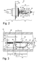
- Figures 1 , 2 show an automotive halogen lamp 10.
- the lamp 10 comprises a base 12 and a burner 14 fixed to the base 12.
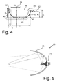
- the lamp 10 may be fixed to a vehicle headlight so as symbolically shown in Figure 5 where the exact position is determined by the protrusions 18a, 18b.
- the protrusion 18b serves as a reference protrusion defining the reference direction R.
- a reference plane for the mounting position of the lamp 10 in the reflector 46 may be defined by the upper portions of the three positioning protrusions.
- a lamp axis X may be defined as longitudinal axis of the lamp 10 perpendicular to this reference plane through the center of the positioning ring 16.
- the radial reference direction R is defined by the center of the reference protrusion 18b.
- Figure 3 shows an enlarged sectional view of the central, circular-cylindrical portion 24 of the vessel 22, and Figure 4 shows the baffle 40 without the filaments 34, 36.
- the filaments 34, 36 are each provided as a single winding structure of filament wire wound around a straight filament axis.
- the filament axis 35 of the first filament 34 and the filament axis 37 of the second filament 36 are arranged in parallel to the longitudinal axis X of the lamp 10.
- the front surface 43 extends at a central tip 42 up to a front height H F of 4.1 mm.
- the side edges 48 comprise a portion 54, which in a side view of Figure 2 or in a sectional view of Figure 3 extend straight and in parallel to the longitudinal axis X of the vessel 22.
- the portions 54 here referred to as extending "straight" in the view of Figure 3 will not be straight as viewed from above.
- the optical functions and measurements of the straight portions 54 of the side edges 48 in the present description refer to the side view, as e. g. shown in Figures 2 and 3 .
- the central, straight portions 54 extend (in side view) straight and in parallel to the longitudinal axis X, i.e. without a variation in height above the bottom surface 41 over a considerably long distance L E .
- the distance L E in the preferred embodiment is 7.2 mm.
- the straight portions 54 start at the front end 42 of the baffle 40 after a distance a of 2 mm and extend up to the back wall 47.
- the distance parameter a is relatively small, i.e. the straight portions 54 start at a very small distance along the lamp axis X from the front end 42 of the baffle 40.
- the side edges 52 within the central, straight portions 54 extend - in side view - exactly straight and in parallel to the lamp axis X.
- the side edges may, in side view, show a certain, limited inclination relative to the lamp axis X.
- Such an inclination may be defined between the start of the straight portion 54 proximate to the first end 42 of the baffle 40 at the coordinate a (in the example shown as 2 mm) along the lamp axis X as a first measuring point, and a second measuring point defined at a fixed distance b of 5 mm along the lamp axis X.
- the second filament 36 is arranged with its filament axis 37 below the straight portions 54 of the edges 48.
- a distance D 2 between the filament axis 37 of the second filament 36 and a plane defined by the straight portions 54 of the edges 48 is 0.3 mm.
- the first filament 34 is arranged partially above and partially below the edge height H E .
- An upper edge 53 of the first filament 34 is 0.5 mm above the plane of the straight portions 54 of the edges 48.
- the axial length L 1 of the first filament 34 almost completely overlaps with the axial length L E of the straight portions 54 of the side edges 48.
- a substantial portion of light emitted from the first filament 34 is shielded at the straight portions 54 rather than at inclined portions of the edges 48, leading to a corresponding straight bright/dark cutoff.
- the filaments 34, 36 operate to emit light.
- Light emitted from the second filament 36 extends freely in all radial directions, whereas light emitted from the first filament 34 is partially shaded by the baffle 40 as described, in particular at the side edges 48.
- Figure 5 shows schematically a headlight 50 where the lamp 10 as described above is schematically shown arranged within a reflector 46.
- Light emitted from the filaments 34, 36 (not shown in Figure 3 ) is reflected by the reflector 46 to form different illumination beams.
- Light from the second (high-beam) filament 36 is shown as a dotted line to be reflected by both the upper and lower part of the reflector 46 to form a high-beam without a bright/dark cutoff.
- Light emitted from the first low-beam filament 34 is shown as a dashed line to be partially shielded by the baffle 40 such that only an upper portion of the reflector 46 is illuminated.
- the upper portion of reflector 46 is shaped to reflect the light from the first filament 34 to form an illumination beam with a horizontal bright/dark cutoff.
- the resulting beam patterns are symmetrical, too.
- the low-beam pattern will have a horizontal bright/dark cutoff.
Landscapes
- Engineering & Computer Science (AREA)
- General Engineering & Computer Science (AREA)
- Non-Portable Lighting Devices Or Systems Thereof (AREA)
- Lighting Device Outwards From Vehicle And Optical Signal (AREA)
Claims (11)
- Leuchte für Kraftfahrzeug-Frontbeleuchtung, umfassend:- einen Sockel (12) zur mechanischen und elektrischen Verbindung mit einem Kraftfahrzeug-Scheinwerfer (50), wobei der Sockel (12) eine Längsachse (X) aufweist,- einen Brenner (14), der an dem Sockel (12) befestigt ist, wobei der Brenner (14) ein geschlossenes durchsichtiges Gefäß (22) umfasst,- mindestens einen ersten und einen zweiten Heizfaden (34, 36), die im Innern des Gefäßes (22) angeordnet sind,- und eine Ablenkscheibe (40), die in der Nähe des ersten Heizfadens (34) angeordnet ist, um Licht, das von dem ersten Heizfaden (34) emittiert wird, teilweise abzuschirmen,- wobei die Ablenkscheibe (40) eine konkave Form aufweist und mindestens eine Bodenfläche (41) und Seitenflächen (45) umfasst, wobei die Seitenflächen (45) in Seitenrändern (48) enden,- und wobei die Ablenkscheibe (40) ferner eine vordere Oberfläche (43) umfasst, die an einem axialen vorderen Ende (42) der Ablenkscheibe (40) angeordnet ist, wobei das axiale vordere Ende (42) das axiale Ende der Ablenkscheibe (40) ist, das dem zweiten Heizfaden (36) am nächsten ist, wobei mindestens ein Teil der vorderen Oberfläche (43) zwischen den ersten und zweiten Heizfäden (34, 36) angeordnet ist, um den zweiten Heizfaden (36) vor Licht, das von dem ersten Heizfaden (34) emittiert wird, abzuschirmen,- wobei sich die vordere Oberfläche (43) höher als die Seitenränder (48) der Ablenkscheibe (40) erstreckt,- und wobei die vordere Oberfläche (43) und die Seitenränder (48) einen schrägen Übergang bilden,- wobei die Seitenränder (48) jeweils einen mittleren Abschnitt (54) umfassen, der sich in Seitenansicht mindestens gerade und parallel zu der Längsachse (X) erstreckt, wobei die geraden mittleren Abschnitte (54) in Seitenansicht in einem Abstand (a) entlang der Achse (X) von dem vorderen Ende (42) aus von nicht mehr als 2,8 mm beginnen,- und wobei eine Randhöhe (HE) als ein Abstand zwischen der Bodenfläche (41) und einer Ebene definiert ist, die zwischen dem geraden mittleren Abschnitt (54) der Seitenränder (48) definiert ist, wobei die Randhöhe (HE) mehr als 2,8 mm beträgt.
- Leuchte nach Anspruch 1, wobei- die geraden mittleren Abschnitte (54) der Seitenränder (48) in Seitenansicht in einem Abstand (a) parallel zu der Längsachse (X) innerhalb eines axialen Bereichs von 1,4 bis 2,8 mm von dem vorderen Ende (42) der Ablenkscheibe (40) aus beginnen.
- Leuchte nach Anspruch 2, wobei- die geraden mittleren Abschnitte (54) innerhalb eines axialen Bereichs von 1,7 bis 2,5 mm von dem ersten Ende (42) aus beginnen.
- Leuchte nach einem der vorhergehenden Ansprüche, wobei- sich die geraden mittleren Abschnitte (54) in Seitenansicht gerade und parallel zur Achse über eine axiale Länge von mindestens 3,5 mm erstrecken.
- Leuchte nach einem der vorhergehenden Ansprüche, wobei- die Ablenkscheibe (40) an einem hinteren Ende, das sich gegenüber dem vorderen Ende (42) befindet, ein flaches Anbringungselement (52) umfasst, das parallel zur Bodenfläche (41) orientiert ist,- wobei das Anbringungselement (52) in einer Ebene angeordnet ist, die von einer Ebene der Bodenfläche (41) um eine Anbringungselementhöhe (HT) entfernt ist,- wobei die Anbringungselementhöhe (HT) kleiner als die Randhöhe (HE) ist.
- Leuchte nach einem der vorhergehenden Ansprüche, wobei- sich die vordere Oberfläche (43) bis auf eine vordere Höhe (HF) erstreckt, die als ein Abstand von der Bodenfläche (41) definiert ist,- wobei die vordere Höhe (HF) mehr als 3,5 mm beträgt.
- Leuchte nach einem der vorhergehenden Ansprüche, wobei- der erste Heizfaden (34) als Wickelstruktur um eine erste Heizfadenachse (35) herum bereitgestellt wird, die parallel zu der Längsachse (X) orientiert ist,- wobei ein erster Heizfadenabstand (D1) definiert ist als ein Abstand zwischen einem oberen Rand des ersten Heizfadens (34) und der Ebene, die durch die geraden mittleren Abschnitte (54) der Seitenränder (48) definiert ist,- wobei der erste Heizfadenabstand (D1) weniger als 0,75 mm beträgt.
- Leuchte nach einem der vorhergehenden Ansprüche, wobei- sich der erste Heizfaden (34) über eine erste axiale Heizfadenlänge (L1) parallel zur Längsachse (X) erstreckt,- wobei die geraden mittleren Abschnitte (54) der Seitenränder (48) über mindestens 70 % der ersten axialen Heizfadenlänge (L1) angeordnet sind.
- Leuchte nach einem der vorhergehenden Ansprüche, wobei- der zweite Heizfaden (36) als Wickelstruktur um eine zweite Heizfadenachse (37) herum bereitgestellt wird, die parallel zur Längsachse (X) orientiert ist,- wobei eine zweite Heizfadenhöhe als ein Abstand zwischen der zweiten Heizfadenachse (37) und der Ebene der Bodenfläche (41) der Ablenkscheibe (40) definiert ist,- wobei die zweite Heizfadenhöhe geringer als die Randhöhe (HE) ist.
- Leuchte nach einem der vorhergehenden Ansprüche, wobei- der Sockel (12) einen Referenzvorsprung (18b) umfasst, der eine radiale Referenzrichtung (R) definiert,- wobei die Heizfäden (34, 36) und die Ablenkscheibe (40) zu einer Symmetrieebene symmetrisch sind, die durch die Leuchtenachse (X) und die Längsreferenzrichtung (R) definiert ist.
- Fahrzeugscheinwerfer, umfassend:- einen Reflektor (46),- und eine Leuchte (10) nach einem der vorhergehenden Ansprüche.
Priority Applications (1)
| Application Number | Priority Date | Filing Date | Title |
|---|---|---|---|
| EP14724367.9A EP2994932B1 (de) | 2013-05-07 | 2014-05-06 | Kraftfahrzeugfrontbeleuchtungslampe mit abblendkappe |
Applications Claiming Priority (3)
| Application Number | Priority Date | Filing Date | Title |
|---|---|---|---|
| EP13166754 | 2013-05-07 | ||
| PCT/EP2014/059157 WO2014180806A1 (en) | 2013-05-07 | 2014-05-06 | Automotive front lighting lamp with baffle |
| EP14724367.9A EP2994932B1 (de) | 2013-05-07 | 2014-05-06 | Kraftfahrzeugfrontbeleuchtungslampe mit abblendkappe |
Publications (2)
| Publication Number | Publication Date |
|---|---|
| EP2994932A1 EP2994932A1 (de) | 2016-03-16 |
| EP2994932B1 true EP2994932B1 (de) | 2016-09-14 |
Family
ID=48227068
Family Applications (1)
| Application Number | Title | Priority Date | Filing Date |
|---|---|---|---|
| EP14724367.9A Not-in-force EP2994932B1 (de) | 2013-05-07 | 2014-05-06 | Kraftfahrzeugfrontbeleuchtungslampe mit abblendkappe |
Country Status (6)
| Country | Link |
|---|---|
| US (1) | US9613793B2 (de) |
| EP (1) | EP2994932B1 (de) |
| JP (1) | JP5948529B1 (de) |
| CN (1) | CN105164786B (de) |
| ES (1) | ES2601380T3 (de) |
| WO (1) | WO2014180806A1 (de) |
Families Citing this family (1)
| Publication number | Priority date | Publication date | Assignee | Title |
|---|---|---|---|---|
| DE202015103408U1 (de) * | 2015-06-29 | 2015-07-09 | Koninklijke Philips N.V. | Abblendkappe für Zweifaden-Glühlampe |
Family Cites Families (25)
| Publication number | Priority date | Publication date | Assignee | Title |
|---|---|---|---|---|
| CA566050A (en) | 1958-11-11 | H. Verbeek Leo | Electrical multiple-filament incandescent lamp | |
| NL189456B (nl) * | 1954-07-24 | Maier Josef | Hoekelement voor het bij elkaar houden van een reeks gestapelde plaatvormige voorwerpen. | |
| GB895825A (en) | 1957-05-17 | 1962-05-09 | Carlo Allioni | Improvements relating to lamps for vehicles |
| DE1224404B (de) | 1961-01-07 | 1966-09-08 | Karl Nowak O H G Ing | Scheinwerferlampe fuer Kraftfahrzeuge |
| DE1772256C3 (de) * | 1968-04-20 | 1978-05-03 | Robert Bosch Gmbh, 7000 Stuttgart | Abblendbarer Fahrzeugscheinwerfer für asymmetrisches Abblendlicht |
| DE1901179A1 (de) * | 1969-01-10 | 1970-08-06 | Patra Patent Treuhand | Zweifadenhalogengluehlampe fuer Kraftfahrzeugscheinwerfer |
| US4385257A (en) * | 1980-11-24 | 1983-05-24 | Edison International, Inc. | Lamp base |
| JPS58147153U (ja) * | 1982-03-29 | 1983-10-03 | 松下電子工業株式会社 | 車両用白熱電球 |
| FR2568721B1 (fr) * | 1984-08-03 | 1986-12-05 | Lampes Elect Fab Reunies | Lampe electrique a incandescence pour vehicule automobile |
| USRE32624E (en) * | 1985-08-09 | 1988-03-15 | Triplex Manufacturing Co. | Shock-reducing lamp assembly for vehicles |
| US4723198A (en) * | 1986-02-06 | 1988-02-02 | Gte Products Corporation | Motor vehicle headlight |
| DE3616673A1 (de) * | 1986-05-16 | 1987-11-19 | Patent Treuhand Ges Fuer Elektrische Gluehlampen Mbh | Halogengluehlampe |
| JP3154085B2 (ja) * | 1995-03-13 | 2001-04-09 | 株式会社小糸製作所 | 電球におけるマウント |
| JP4057090B2 (ja) * | 1996-06-06 | 2008-03-05 | 本田技研工業株式会社 | 車両用電球 |
| DE10145427A1 (de) * | 2001-09-14 | 2003-04-03 | Patent Treuhand Ges Fuer Elektrische Gluehlampen Mbh | Glühlampe für Kraftfahrzeugscheinwerfer |
| JP2003127760A (ja) * | 2001-10-30 | 2003-05-08 | Koito Mfg Co Ltd | 自動車用ヘッドランプ |
| JP4893159B2 (ja) * | 2006-08-24 | 2012-03-07 | ウシオ電機株式会社 | フィラメントランプおよび光照射式加熱処理装置 |
| DE102006052950A1 (de) * | 2006-11-09 | 2008-05-15 | Patent-Treuhand-Gesellschaft für elektrische Glühlampen mbH | Halogenglühlampe |
| DE102006060029A1 (de) | 2006-12-19 | 2008-06-26 | Patent-Treuhand-Gesellschaft für elektrische Glühlampen mbH | Abblendkappe mit Wendel |
| DE102006060419A1 (de) * | 2006-12-20 | 2008-06-26 | Patent-Treuhand-Gesellschaft für elektrische Glühlampen mbH | Zweiwendellampe |
| DE102006060772A1 (de) * | 2006-12-21 | 2008-06-26 | Patent-Treuhand-Gesellschaft für elektrische Glühlampen mbH | Abblendkappe für Zweiwendelhalogenlampe unterschiedlicher Leistung zur Nutzlichtherhöhung |
| JP4983278B2 (ja) * | 2007-01-31 | 2012-07-25 | スタンレー電気株式会社 | 車両用灯具 |
| DE102007048387A1 (de) | 2007-10-09 | 2009-04-16 | Osram Gesellschaft mit beschränkter Haftung | Lampe, insbesondere Fahrzeuglampe |
| US7722210B2 (en) * | 2008-07-02 | 2010-05-25 | Osram Sylvania Inc. | Automotive lamp and reflector for low beam and advanced forward lighting system |
| US8152327B2 (en) * | 2009-10-02 | 2012-04-10 | Coast Cutlery Company | Focusing lens system |
-
2014
- 2014-05-06 EP EP14724367.9A patent/EP2994932B1/de not_active Not-in-force
- 2014-05-06 WO PCT/EP2014/059157 patent/WO2014180806A1/en not_active Ceased
- 2014-05-06 US US14/889,600 patent/US9613793B2/en not_active Expired - Fee Related
- 2014-05-06 ES ES14724367.9T patent/ES2601380T3/es active Active
- 2014-05-06 JP JP2016512334A patent/JP5948529B1/ja not_active Expired - Fee Related
- 2014-05-06 CN CN201480025841.6A patent/CN105164786B/zh not_active Expired - Fee Related
Also Published As
| Publication number | Publication date |
|---|---|
| JP2016522966A (ja) | 2016-08-04 |
| CN105164786A (zh) | 2015-12-16 |
| CN105164786B (zh) | 2017-07-25 |
| US9613793B2 (en) | 2017-04-04 |
| US20160086789A1 (en) | 2016-03-24 |
| JP5948529B1 (ja) | 2016-07-06 |
| EP2994932A1 (de) | 2016-03-16 |
| ES2601380T3 (es) | 2017-02-15 |
| WO2014180806A1 (en) | 2014-11-13 |
Similar Documents
| Publication | Publication Date | Title |
|---|---|---|
| US7597466B2 (en) | Vehicle lamp | |
| KR100450646B1 (ko) | 반사기와램프를갖는자동차헤드라이트 | |
| JP2015207512A (ja) | 車両前照灯用led光源装置 | |
| EP0082992A2 (de) | Zweifadenlampe für Autoscheinwerfer | |
| EP2994932B1 (de) | Kraftfahrzeugfrontbeleuchtungslampe mit abblendkappe | |
| JP5027246B2 (ja) | 遮蔽装置 | |
| JP7058166B2 (ja) | 車両用前照灯 | |
| EP3055877B1 (de) | Vibrationsfeste lampe für kraftfahrzeugscheinwerfer | |
| JP2011154913A (ja) | 光学ユニット | |
| EP3044806B1 (de) | Vibrationsfeste automobilfrontbeleuchtungslampe | |
| JP6368356B2 (ja) | 自動車の前方照射のためのダブルフィラメント白熱ランプ | |
| US6822392B2 (en) | Incandescent lamp for motor vehicle headlights | |
| KR20190015486A (ko) | 반사기 내에 2개의 필라멘트를 갖고 이러한 램프를 장착한 차량 헤드라이트 | |
| JP2003051204A (ja) | 車両用灯具 | |
| EP3957554B1 (de) | Fahrradscheinwerfer | |
| US8106574B2 (en) | Electric bulb for use in a vehicle headlamp | |
| JPH09115303A (ja) | 車両用の前照灯 | |
| JPWO2007132541A1 (ja) | 車両用高圧放電ランプ | |
| JP2010132228A (ja) | 二輪車用前照灯 |
Legal Events
| Date | Code | Title | Description |
|---|---|---|---|
| PUAI | Public reference made under article 153(3) epc to a published international application that has entered the european phase |
Free format text: ORIGINAL CODE: 0009012 |
|
| 17P | Request for examination filed |
Effective date: 20151207 |
|
| AK | Designated contracting states |
Kind code of ref document: A1 Designated state(s): AL AT BE BG CH CY CZ DE DK EE ES FI FR GB GR HR HU IE IS IT LI LT LU LV MC MK MT NL NO PL PT RO RS SE SI SK SM TR |
|
| AX | Request for extension of the european patent |
Extension state: BA ME |
|
| GRAP | Despatch of communication of intention to grant a patent |
Free format text: ORIGINAL CODE: EPIDOSNIGR1 |
|
| GRAS | Grant fee paid |
Free format text: ORIGINAL CODE: EPIDOSNIGR3 |
|
| DAX | Request for extension of the european patent (deleted) | ||
| INTG | Intention to grant announced |
Effective date: 20160708 |
|
| GRAA | (expected) grant |
Free format text: ORIGINAL CODE: 0009210 |
|
| AK | Designated contracting states |
Kind code of ref document: B1 Designated state(s): AL AT BE BG CH CY CZ DE DK EE ES FI FR GB GR HR HU IE IS IT LI LT LU LV MC MK MT NL NO PL PT RO RS SE SI SK SM TR |
|
| REG | Reference to a national code |
Ref country code: GB Ref legal event code: FG4D |
|
| REG | Reference to a national code |
Ref country code: CH Ref legal event code: EP |
|
| REG | Reference to a national code |
Ref country code: IE Ref legal event code: FG4D |
|
| REG | Reference to a national code |
Ref country code: AT Ref legal event code: REF Ref document number: 829808 Country of ref document: AT Kind code of ref document: T Effective date: 20161015 |
|
| REG | Reference to a national code |
Ref country code: DE Ref legal event code: R096 Ref document number: 602014003679 Country of ref document: DE |
|
| REG | Reference to a national code |
Ref country code: LT Ref legal event code: MG4D |
|
| REG | Reference to a national code |
Ref country code: NL Ref legal event code: MP Effective date: 20160914 |
|
| PG25 | Lapsed in a contracting state [announced via postgrant information from national office to epo] |
Ref country code: FI Free format text: LAPSE BECAUSE OF FAILURE TO SUBMIT A TRANSLATION OF THE DESCRIPTION OR TO PAY THE FEE WITHIN THE PRESCRIBED TIME-LIMIT Effective date: 20160914 Ref country code: RS Free format text: LAPSE BECAUSE OF FAILURE TO SUBMIT A TRANSLATION OF THE DESCRIPTION OR TO PAY THE FEE WITHIN THE PRESCRIBED TIME-LIMIT Effective date: 20160914 Ref country code: NO Free format text: LAPSE BECAUSE OF FAILURE TO SUBMIT A TRANSLATION OF THE DESCRIPTION OR TO PAY THE FEE WITHIN THE PRESCRIBED TIME-LIMIT Effective date: 20161214 Ref country code: LT Free format text: LAPSE BECAUSE OF FAILURE TO SUBMIT A TRANSLATION OF THE DESCRIPTION OR TO PAY THE FEE WITHIN THE PRESCRIBED TIME-LIMIT Effective date: 20160914 Ref country code: HR Free format text: LAPSE BECAUSE OF FAILURE TO SUBMIT A TRANSLATION OF THE DESCRIPTION OR TO PAY THE FEE WITHIN THE PRESCRIBED TIME-LIMIT Effective date: 20160914 |
|
| REG | Reference to a national code |
Ref country code: AT Ref legal event code: MK05 Ref document number: 829808 Country of ref document: AT Kind code of ref document: T Effective date: 20160914 Ref country code: ES Ref legal event code: FG2A Ref document number: 2601380 Country of ref document: ES Kind code of ref document: T3 Effective date: 20170215 |
|
| PG25 | Lapsed in a contracting state [announced via postgrant information from national office to epo] |
Ref country code: NL Free format text: LAPSE BECAUSE OF FAILURE TO SUBMIT A TRANSLATION OF THE DESCRIPTION OR TO PAY THE FEE WITHIN THE PRESCRIBED TIME-LIMIT Effective date: 20160914 Ref country code: SE Free format text: LAPSE BECAUSE OF FAILURE TO SUBMIT A TRANSLATION OF THE DESCRIPTION OR TO PAY THE FEE WITHIN THE PRESCRIBED TIME-LIMIT Effective date: 20160914 Ref country code: GR Free format text: LAPSE BECAUSE OF FAILURE TO SUBMIT A TRANSLATION OF THE DESCRIPTION OR TO PAY THE FEE WITHIN THE PRESCRIBED TIME-LIMIT Effective date: 20161215 Ref country code: LV Free format text: LAPSE BECAUSE OF FAILURE TO SUBMIT A TRANSLATION OF THE DESCRIPTION OR TO PAY THE FEE WITHIN THE PRESCRIBED TIME-LIMIT Effective date: 20160914 |
|
| PG25 | Lapsed in a contracting state [announced via postgrant information from national office to epo] |
Ref country code: EE Free format text: LAPSE BECAUSE OF FAILURE TO SUBMIT A TRANSLATION OF THE DESCRIPTION OR TO PAY THE FEE WITHIN THE PRESCRIBED TIME-LIMIT Effective date: 20160914 Ref country code: RO Free format text: LAPSE BECAUSE OF FAILURE TO SUBMIT A TRANSLATION OF THE DESCRIPTION OR TO PAY THE FEE WITHIN THE PRESCRIBED TIME-LIMIT Effective date: 20160914 |
|
| REG | Reference to a national code |
Ref country code: FR Ref legal event code: PLFP Year of fee payment: 4 |
|
| PG25 | Lapsed in a contracting state [announced via postgrant information from national office to epo] |
Ref country code: PL Free format text: LAPSE BECAUSE OF FAILURE TO SUBMIT A TRANSLATION OF THE DESCRIPTION OR TO PAY THE FEE WITHIN THE PRESCRIBED TIME-LIMIT Effective date: 20160914 Ref country code: AT Free format text: LAPSE BECAUSE OF FAILURE TO SUBMIT A TRANSLATION OF THE DESCRIPTION OR TO PAY THE FEE WITHIN THE PRESCRIBED TIME-LIMIT Effective date: 20160914 Ref country code: CZ Free format text: LAPSE BECAUSE OF FAILURE TO SUBMIT A TRANSLATION OF THE DESCRIPTION OR TO PAY THE FEE WITHIN THE PRESCRIBED TIME-LIMIT Effective date: 20160914 Ref country code: SM Free format text: LAPSE BECAUSE OF FAILURE TO SUBMIT A TRANSLATION OF THE DESCRIPTION OR TO PAY THE FEE WITHIN THE PRESCRIBED TIME-LIMIT Effective date: 20160914 Ref country code: IS Free format text: LAPSE BECAUSE OF FAILURE TO SUBMIT A TRANSLATION OF THE DESCRIPTION OR TO PAY THE FEE WITHIN THE PRESCRIBED TIME-LIMIT Effective date: 20170114 Ref country code: SK Free format text: LAPSE BECAUSE OF FAILURE TO SUBMIT A TRANSLATION OF THE DESCRIPTION OR TO PAY THE FEE WITHIN THE PRESCRIBED TIME-LIMIT Effective date: 20160914 Ref country code: BG Free format text: LAPSE BECAUSE OF FAILURE TO SUBMIT A TRANSLATION OF THE DESCRIPTION OR TO PAY THE FEE WITHIN THE PRESCRIBED TIME-LIMIT Effective date: 20161214 Ref country code: BE Free format text: LAPSE BECAUSE OF FAILURE TO SUBMIT A TRANSLATION OF THE DESCRIPTION OR TO PAY THE FEE WITHIN THE PRESCRIBED TIME-LIMIT Effective date: 20160914 Ref country code: PT Free format text: LAPSE BECAUSE OF FAILURE TO SUBMIT A TRANSLATION OF THE DESCRIPTION OR TO PAY THE FEE WITHIN THE PRESCRIBED TIME-LIMIT Effective date: 20170116 |
|
| REG | Reference to a national code |
Ref country code: DE Ref legal event code: R097 Ref document number: 602014003679 Country of ref document: DE |
|
| PLBE | No opposition filed within time limit |
Free format text: ORIGINAL CODE: 0009261 |
|
| STAA | Information on the status of an ep patent application or granted ep patent |
Free format text: STATUS: NO OPPOSITION FILED WITHIN TIME LIMIT |
|
| PG25 | Lapsed in a contracting state [announced via postgrant information from national office to epo] |
Ref country code: DK Free format text: LAPSE BECAUSE OF FAILURE TO SUBMIT A TRANSLATION OF THE DESCRIPTION OR TO PAY THE FEE WITHIN THE PRESCRIBED TIME-LIMIT Effective date: 20160914 |
|
| 26N | No opposition filed |
Effective date: 20170615 |
|
| PG25 | Lapsed in a contracting state [announced via postgrant information from national office to epo] |
Ref country code: LU Free format text: LAPSE BECAUSE OF NON-PAYMENT OF DUE FEES Effective date: 20170531 |
|
| PG25 | Lapsed in a contracting state [announced via postgrant information from national office to epo] |
Ref country code: SI Free format text: LAPSE BECAUSE OF FAILURE TO SUBMIT A TRANSLATION OF THE DESCRIPTION OR TO PAY THE FEE WITHIN THE PRESCRIBED TIME-LIMIT Effective date: 20160914 |
|
| REG | Reference to a national code |
Ref country code: CH Ref legal event code: PL |
|
| PG25 | Lapsed in a contracting state [announced via postgrant information from national office to epo] |
Ref country code: MC Free format text: LAPSE BECAUSE OF FAILURE TO SUBMIT A TRANSLATION OF THE DESCRIPTION OR TO PAY THE FEE WITHIN THE PRESCRIBED TIME-LIMIT Effective date: 20160914 |
|
| REG | Reference to a national code |
Ref country code: IE Ref legal event code: MM4A |
|
| PG25 | Lapsed in a contracting state [announced via postgrant information from national office to epo] |
Ref country code: CH Free format text: LAPSE BECAUSE OF NON-PAYMENT OF DUE FEES Effective date: 20170531 Ref country code: LI Free format text: LAPSE BECAUSE OF NON-PAYMENT OF DUE FEES Effective date: 20170531 |
|
| REG | Reference to a national code |
Ref country code: FR Ref legal event code: TP Owner name: LUMILEDS HOLDING B.V., NL Effective date: 20180126 Ref country code: FR Ref legal event code: CA Effective date: 20180126 |
|
| PG25 | Lapsed in a contracting state [announced via postgrant information from national office to epo] |
Ref country code: LU Free format text: LAPSE BECAUSE OF NON-PAYMENT OF DUE FEES Effective date: 20170506 |
|
| PG25 | Lapsed in a contracting state [announced via postgrant information from national office to epo] |
Ref country code: IE Free format text: LAPSE BECAUSE OF NON-PAYMENT OF DUE FEES Effective date: 20170506 |
|
| REG | Reference to a national code |
Ref country code: FR Ref legal event code: PLFP Year of fee payment: 5 |
|
| REG | Reference to a national code |
Ref country code: ES Ref legal event code: PC2A Effective date: 20180607 Owner name: LUMILEDS HOLDINGS B.V. |
|
| PG25 | Lapsed in a contracting state [announced via postgrant information from national office to epo] |
Ref country code: MT Free format text: LAPSE BECAUSE OF NON-PAYMENT OF DUE FEES Effective date: 20170506 |
|
| REG | Reference to a national code |
Ref country code: GB Ref legal event code: 732E Free format text: REGISTERED BETWEEN 20180920 AND 20180926 |
|
| PG25 | Lapsed in a contracting state [announced via postgrant information from national office to epo] |
Ref country code: AL Free format text: LAPSE BECAUSE OF FAILURE TO SUBMIT A TRANSLATION OF THE DESCRIPTION OR TO PAY THE FEE WITHIN THE PRESCRIBED TIME-LIMIT Effective date: 20160914 |
|
| REG | Reference to a national code |
Ref country code: DE Ref legal event code: R081 Ref document number: 602014003679 Country of ref document: DE Owner name: LUMILEDS HOLDING B.V., NL Free format text: FORMER OWNER: PHILIPS GMBH, 20099 HAMBURG, DE |
|
| PG25 | Lapsed in a contracting state [announced via postgrant information from national office to epo] |
Ref country code: HU Free format text: LAPSE BECAUSE OF FAILURE TO SUBMIT A TRANSLATION OF THE DESCRIPTION OR TO PAY THE FEE WITHIN THE PRESCRIBED TIME-LIMIT; INVALID AB INITIO Effective date: 20140506 |
|
| PG25 | Lapsed in a contracting state [announced via postgrant information from national office to epo] |
Ref country code: CY Free format text: LAPSE BECAUSE OF FAILURE TO SUBMIT A TRANSLATION OF THE DESCRIPTION OR TO PAY THE FEE WITHIN THE PRESCRIBED TIME-LIMIT Effective date: 20160914 |
|
| PG25 | Lapsed in a contracting state [announced via postgrant information from national office to epo] |
Ref country code: MK Free format text: LAPSE BECAUSE OF FAILURE TO SUBMIT A TRANSLATION OF THE DESCRIPTION OR TO PAY THE FEE WITHIN THE PRESCRIBED TIME-LIMIT Effective date: 20160914 |
|
| PG25 | Lapsed in a contracting state [announced via postgrant information from national office to epo] |
Ref country code: TR Free format text: LAPSE BECAUSE OF FAILURE TO SUBMIT A TRANSLATION OF THE DESCRIPTION OR TO PAY THE FEE WITHIN THE PRESCRIBED TIME-LIMIT Effective date: 20160914 |
|
| PGFP | Annual fee paid to national office [announced via postgrant information from national office to epo] |
Ref country code: DE Payment date: 20200529 Year of fee payment: 7 Ref country code: ES Payment date: 20200609 Year of fee payment: 7 Ref country code: FR Payment date: 20200528 Year of fee payment: 7 |
|
| PGFP | Annual fee paid to national office [announced via postgrant information from national office to epo] |
Ref country code: GB Payment date: 20200528 Year of fee payment: 7 Ref country code: IT Payment date: 20200522 Year of fee payment: 7 |
|
| REG | Reference to a national code |
Ref country code: DE Ref legal event code: R119 Ref document number: 602014003679 Country of ref document: DE |
|
| GBPC | Gb: european patent ceased through non-payment of renewal fee |
Effective date: 20210506 |
|
| PG25 | Lapsed in a contracting state [announced via postgrant information from national office to epo] |
Ref country code: GB Free format text: LAPSE BECAUSE OF NON-PAYMENT OF DUE FEES Effective date: 20210506 Ref country code: DE Free format text: LAPSE BECAUSE OF NON-PAYMENT OF DUE FEES Effective date: 20211201 |
|
| PG25 | Lapsed in a contracting state [announced via postgrant information from national office to epo] |
Ref country code: FR Free format text: LAPSE BECAUSE OF NON-PAYMENT OF DUE FEES Effective date: 20210531 |
|
| REG | Reference to a national code |
Ref country code: ES Ref legal event code: FD2A Effective date: 20220801 |
|
| PG25 | Lapsed in a contracting state [announced via postgrant information from national office to epo] |
Ref country code: ES Free format text: LAPSE BECAUSE OF NON-PAYMENT OF DUE FEES Effective date: 20210507 |
|
| PG25 | Lapsed in a contracting state [announced via postgrant information from national office to epo] |
Ref country code: IT Free format text: LAPSE BECAUSE OF NON-PAYMENT OF DUE FEES Effective date: 20200506 |
|
| PG25 | Lapsed in a contracting state [announced via postgrant information from national office to epo] |
Ref country code: IT Free format text: LAPSE BECAUSE OF NON-PAYMENT OF DUE FEES Effective date: 20210506 |