EP2992673B1 - Verfahren, vorrichtung und computerprogramprodukt zum erhalt von bildern mit hohem dynamikbereich - Google Patents
Verfahren, vorrichtung und computerprogramprodukt zum erhalt von bildern mit hohem dynamikbereich Download PDFInfo
- Publication number
- EP2992673B1 EP2992673B1 EP14792324.7A EP14792324A EP2992673B1 EP 2992673 B1 EP2992673 B1 EP 2992673B1 EP 14792324 A EP14792324 A EP 14792324A EP 2992673 B1 EP2992673 B1 EP 2992673B1
- Authority
- EP
- European Patent Office
- Prior art keywords
- pixel
- exposure image
- image
- value
- short exposure
- Prior art date
- Legal status (The legal status is an assumption and is not a legal conclusion. Google has not performed a legal analysis and makes no representation as to the accuracy of the status listed.)
- Active
Links
Images


Classifications
-
- H—ELECTRICITY
- H04—ELECTRIC COMMUNICATION TECHNIQUE
- H04N—PICTORIAL COMMUNICATION, e.g. TELEVISION
- H04N1/00—Scanning, transmission or reproduction of documents or the like, e.g. facsimile transmission; Details thereof
- H04N1/387—Composing, repositioning or otherwise geometrically modifying originals
- H04N1/3871—Composing, repositioning or otherwise geometrically modifying originals the composed originals being of different kinds, e.g. low- and high-resolution originals
-
- H—ELECTRICITY
- H04—ELECTRIC COMMUNICATION TECHNIQUE
- H04N—PICTORIAL COMMUNICATION, e.g. TELEVISION
- H04N23/00—Cameras or camera modules comprising electronic image sensors; Control thereof
- H04N23/70—Circuitry for compensating brightness variation in the scene
- H04N23/741—Circuitry for compensating brightness variation in the scene by increasing the dynamic range of the image compared to the dynamic range of the electronic image sensors
-
- H—ELECTRICITY
- H04—ELECTRIC COMMUNICATION TECHNIQUE
- H04N—PICTORIAL COMMUNICATION, e.g. TELEVISION
- H04N23/00—Cameras or camera modules comprising electronic image sensors; Control thereof
- H04N23/80—Camera processing pipelines; Components thereof
- H04N23/84—Camera processing pipelines; Components thereof for processing colour signals
-
- H—ELECTRICITY
- H04—ELECTRIC COMMUNICATION TECHNIQUE
- H04N—PICTORIAL COMMUNICATION, e.g. TELEVISION
- H04N25/00—Circuitry of solid-state image sensors [SSIS]; Control thereof
- H04N25/50—Control of the SSIS exposure
- H04N25/57—Control of the dynamic range
- H04N25/58—Control of the dynamic range involving two or more exposures
- H04N25/587—Control of the dynamic range involving two or more exposures acquired sequentially, e.g. using the combination of odd and even image fields
- H04N25/589—Control of the dynamic range involving two or more exposures acquired sequentially, e.g. using the combination of odd and even image fields with different integration times, e.g. short and long exposures
-
- H—ELECTRICITY
- H04—ELECTRIC COMMUNICATION TECHNIQUE
- H04N—PICTORIAL COMMUNICATION, e.g. TELEVISION
- H04N2201/00—Indexing scheme relating to scanning, transmission or reproduction of documents or the like, and to details thereof
- H04N2201/0077—Types of the still picture apparatus
- H04N2201/0084—Digital still camera
Definitions
- the present disclosure relates to an image processing technology, and in particular, relates to a method and a device for obtaining a high dynamic range image.
- an imaging apparatus includes: an imaging device outputting, during a unit period of time, a long-exposure-time image signal having a relatively long exposure time and a short exposure-time image signal having a relatively short exposure time; a first clipping processing mechanism clipping a part not lower than a first signal level of a luminanee signal obtained from the long-exposure-time image signal; a second clipping processing mechanism clipping a part not higher than a second signal level of a luminance signal obtained from the short-exposure-time image signal; and a signal processing mechanism generating a synthesized image signal having a dynamic range wider than dynamic ranges of both of the image signals by synthesizing the clipped image signals.
- JP2003244719 discloses an image composite method and apparatus thereof capable of smoothing joints of color changes and preventing S/N and resolution from being deteriorated in the case of composing a high sensitivity image and a low sensitivity image to produce a composite image with a wide dynamic range.
- the image composite method and apparatus thereof uses only a color signal SH of the high sensitivity image for a range of the lightness darker than a first prescribed value SA, uses only a color signal Sck obtained from a difference signal for a range brighter than a second prescribed value SB brighter than the first prescribed value SA, and uses a color signal resulting from summing the color signal SH of the high sensitivity image and the color signal Sck obtained from the difference signal by using a weighting coefficient to produce the color signal of the composite image.
- each low dynamic range image is responsible for collecting different details of the high dynamic scene
- an underexposed image mainly records high brightness details of the scene
- an overexposed image is used to record the dark area of the scene.
- One method for obtaining a high dynamic range image is as follows. Firstly, a long exposure image (having a large exposure) and a short exposure image (having a small exposure) of the same scene are obtained. Then, the pixel value of each pixel in the long exposure image is combined with the pixel value of each pixel in the short exposure image according to a certain proportion to obtain the pixel value of each pixel in the high dynamic range image.
- the color of the image obtained by the above method is darker, which is because: a brightness value of the overexposed area of the long exposure image is large, but the long exposure image does not provide any color information; a brightness value of the short exposure image is small, but the short exposure image provides some color information; the brightness value of the combined image is much larger than the brightness value of the short exposure image, but the color information of the combined image is provided by the short exposure image. Therefore, the color value of the combined image is relatively small, which results in that the color of the combined image is dark.
- the purpose of the present disclosure is to solve at least one of the problems existing in the conventional technology to at least some extent.
- a method for obtaining a high dynamic range image includes: obtaining a pixel value of each pixel in a long exposure image and a short exposure image of a same scene; determining a brightness value of each pixel in the long exposure image and the short exposure image according to the pixel value of each pixel in the long exposure image and the short exposure image; determining an objective brightness value of each pixel in a combined image combining the long exposure image with the short exposure image according to the brightness value of each pixel in the long exposure image and the short exposure image; determining a color value of each pixel in the long exposure image and the short exposure image according to the pixel value and the brightness value of each pixel in the long exposure image and the short exposure image; determining a color value of each pixel in the combined image according to the color value of each pixel in the long exposure image and the short exposure image; correcting the color value of each pixel in the combined image according to the brightness value of each pixel in the long exposure image
- the method for obtaining a high dynamic range image by obtaining the pixel value of each pixel in the long exposure image and the short exposure image of the same scene, determining the color value and the brightness value of each pixel in the long exposure image, determining the objective color value of the combined image and correcting the color value of the combined image, and combining the images according to the objective color value and the corrected color value, a problem of the dark color of the combined image is solved, and the color value of the combined image is increased.
- a device for obtaining a high dynamic range image includes: a first obtaining module, configured to obtain the pixel value of each pixel a long exposure image and a short exposure image of a same scene; a first determining module, configured to determine a brightness value of each pixel in the long exposure image and the short exposure image according to the pixel value of each pixel in the long exposure image and the short exposure image; a second determining module, configured to determine an objective brightness value of each pixel in a combined image combining the long exposure image with the short exposure image according to the brightness value of each pixel in the long exposure image and the short exposure image; a third determining module, configured to determine a color value of each pixel in the long exposure image and the short exposure image according to the pixel value and the brightness value of each pixel in the long exposure image and the short exposure image, and to determine a color value of each pixel in the combined image according to the color value of each pixel in the long exposure image and the short exposure image and the
- the device for obtaining a high dynamic range image by obtaining the pixel value of each pixel in the long exposure image and the short exposure image of the same scene, determining the color value and the brightness value of each pixel in the long exposure image, determining the objective color value of the combined image and correcting the color value of the combined image, and combining the images according to the objective color value and the corrected color value, a problem of the dark color of the combined image is solved, and the color value of the combined image is increased.
- the color correcting module comprises: a fourth obtaining unit, configured to generate a feature weight value of each pixel in the long exposure image and the short exposure image according to the brightness value of each pixel in the long exposure image and the short exposure image; a fifth obtaining unit, configured to generate a feature brightness value of each pixel in the combined image according to the feature weight value and the brightness value of each pixel in the long exposure image and the short exposure image; and a correcting unit, configured to correct the color value of each pixel in the combined image according to the feature brightness value and the objective brightness value of each pixel in the combined image to obtain the corrected color value of each pixel in the combined image.
- a computer program comprising computer-executable instructions to perform the method, when the program is run on a device as described above, according to any one of the steps of any one of the embodiments of the method disclosed above.
- a structure in which a first feature is "on" a second feature may include an embodiment in which the first feature directly contacts the second feature, and may include an embodiment in which an additional feature is formed between the first feature and the second feature so that the first feature does not directly contact the second feature.
- connection refers to a relationship in which structures are secured or attached to one another either directly or indirectly through intervening structures, as well as both movable or rigid attachments or relationships, unless expressly described otherwise.
- connection and variations thereof are used broadly and encompass both direct and indirect mountings, connections, supports, and couplings. Further, “connected” are not restricted to physical or mechanical connections.
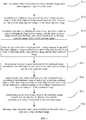
- the method for obtaining a high dynamic range image includes the following steps: S11, obtaining a pixel value of each pixel in a long exposure image and a short exposure image of a same scene; S12, determining a brightness value of each pixel in the long exposure image and the short exposure image according to the pixel value of each pixel in the long exposure image and the short exposure image; S13, determining an objective brightness value of each pixel in a combined image combining the long exposure image with the short exposure image according to the brightness value of each pixel in the long exposure image and the short exposure image; S14, determining a color value of each pixel in the long exposure image and the short exposure image according to the pixel value and the brightness value of each pixel in the long exposure image and the short exposure image; S15, determining a color value of each pixel in the combined image according to the color value of each pixel in the long exposure image and the short exposure image; S16, correcting the color value of each pixel in
- a long exposure time and a short exposure time of a camera equipment are firstly set up, and then the camera equipment is used to take the long exposure image and the short exposure image of the same scene. Subsequently, the pixel value of each pixel in the long exposure image and the short exposure image are obtained.
- the long exposure time and the short exposure time do not have specific values. Compared with a normal exposure image, an exposure of the long exposure image is relatively large, and the short exposure image is underexposed.
- the long exposure image has an exposure time which is larger than the exposure time of the short exposure image, typically at least 2 times larger, and preferably at least 5 times larger.
- the long exposure time is set in order to make a darker area of the scene exposed correctly to reflect enough details
- the short exposure time is set in order to make a brighter area of the scene exposed correctly to reflect enough details.
- the long exposure image and the short exposure image should be aligned in a pixel level to prevent ghost image effects in the final combined high dynamic range image.
- FIG. 2 is a flow chart showing a method for determining an objective brightness value of each pixel in a combined image according to an embodiment of the present disclosure.
- the combined image here is not the final image, but merely an intermediate image during the process of obtaining the final image, and the values of the combined image are obtained by combining the values of the long exposure image with the values of the short exposure image.
- the objective brightness value of each pixel in the combined image may be determined as follows.
- an average brightness value of the short exposure image is obtained according to the brightness value of each pixel in the short exposure image. Specifically, a sum of the brightness value of each pixel in the short exposure image is firstly obtained, and then the sum is divided by a number of pixels in the short exposure image.
- a proportion of the short exposure image is determined according to the average brightness value of the short exposure image.
- the predetermined value K is set in a range from 0.5 to 1.5, and the proportion A is limited in a range from 20% to 50%.
- the objective brightness value of each pixel in the combined image is determined according to the brightness value of each pixel in the long exposure image and the short exposure image, and the proportion of the short exposure image.
- FIG. 3 is a flow chart showing a method for correcting a color value of each pixel in a combined image according to an embodiment of the present disclosure.
- the color value of each pixel in the combined image may be corrected as follows.
- a feature weight value of each pixel in the long exposure image and the short exposure image is generated according to the brightness value of each pixel both in the long exposure image and the short exposure image.
- the pixel value of an 8-bit image generally ranges from 0 to 255. After observing a large number of images, it is found that the brightness value of a detail concentrated area of the image is about 128 (i.e., a medium pixel value of the pixel values in the image). Therefore, the closer to 128 the brightness value of the pixel in the image is, the more detail information of the image can be reflected, and thus the larger the feature weight value of the pixel should be.
- a feature brightness value of each pixel in the combined image is generated according to the feature weight value and the brightness value of each pixel in the long exposure image and the short exposure image.
- the color value of each pixel in the combined image is corrected according to the feature brightness value and the objective brightness value of each pixel in the combined image so as to obtain the corrected color value of each pixel in the combined image.
- step S11 before obtaining the pixel value of each pixel in the long exposure image and the short exposure image, it can be determined whether there is a need to obtain a high dynamic range image, and if yes, step S11 is executed, and if no, the normal exposure image is captured, and an ordinary dynamic range image is obtained.
- the method for obtaining a high dynamic range image by obtaining the pixel value of each pixel in the long exposure image and the short exposure image of the same scene, determining the color value and the brightness value of each pixel in the long exposure image, determining the objective color value of the combined image and correcting the color value of the combined image, and combining the images according to the objective color value and the corrected color value, a problem of the dark color of the combined image is solved, and the color value of the combined image is increased.
- a device for obtaining a high dynamic range image includes a first obtaining module 10, a first determining module 20, a second determining module 30, a third determining module 40, a color correcting module 50, a fourth determining module 60 and a second obtaining module 70.
- the first obtaining module 10 is configured to obtain a pixel value of each pixel in a long exposure image and a short exposure image of a same scene.
- the first determining module 20 is configured to determine a brightness value of each pixel in the long exposure image and the short exposure image according to the pixel value of each pixel in the long exposure image and the short exposure image.
- the second determining module 30 is configured to determine an objective brightness value of each pixel in a combined image combining the long exposure image with the short exposure image according to the brightness value of each pixel in the long exposure image and the short exposure image.
- the third determining module 40 is configured to determine a color value of each pixel in the long exposure image and the short exposure image according to the pixel value and the brightness value of each pixel in the long exposure image and the short exposure image, and to determine a color value of each pixel in the combined image according to the color value of each pixel in the long exposure image and the short exposure image.
- the color correcting module 50 is configured to correct the color value of each pixel in the combined image according to the brightness value of each pixel in the long exposure image and the short exposure image and the objective brightness value of each pixel in the combined image so as to obtain a corrected color value of each pixel in the combined image.
- the fourth determining module 60 is configured to determine a pixel value of each pixel in the combined image according to the objective brightness value and the corrected color value of each pixel in the combined image.
- the second obtaining module 70 is configured to obtain a high dynamic range image according to the pixel value of each pixel in the combined image.
- the first obtaining module 10 can obtain the long exposure image and the short exposure image of the same scene by adjusting the exposure time and the gain value.
- the second determining module 30 may include a first obtaining unit 301, a second obtaining unit 302 and a third obtaining unit 303.
- the first obtaining unit 301 is configured to obtain an average brightness value of the short exposure image according to the brightness value of the short exposure image.
- the average brightness value of each pixel in the short exposure image may be determined by obtaining a sum of the brightness value of each pixel in the short exposure image, and then dividing the sum by a number of pixels in the short exposure image.
- the second obtaining unit 302 is configured to determine a proportion of the short exposure image according to the average brightness value of the short exposure image.
- the third obtaining unit 303 is configured to determine the objective brightness value of each pixel in the combined image according to the brightness value of each pixel in the long exposure image and the short exposure image and the proportion of the short exposure image.
- the color correcting module 50 may include a fourth obtaining unit 501, a fifth obtaining unit 502 and a correcting unit 503.
- the fourth obtaining unit 501 is configured to generate a feature weight value of each pixel in the long exposure image and the short exposure image according to the brightness value of each pixel both in the long exposure image and the short exposure image.
- the fifth obtaining unit 502 is configured to generate a feature brightness value of each pixel in the combined image according to the feature weight value and the brightness value of each pixel in the long exposure image and the short exposure image.
- the correcting unit 503 is configured to correct the color value of each pixel in the combined image according to the feature brightness value and the objective brightness value of each pixel in the combined image.
- the device for obtaining the high dynamic range image may further include a function selection switch configured to be turned on or off according to whether there is a need to process an image to obtain a high dynamic range image.
- a function selection switch configured to be turned on or off according to whether there is a need to process an image to obtain a high dynamic range image.
- the function selection switch can be turned on so as to process the image to obtain a high dynamic range image, thus expanding the dynamic range of the image and increasing visual details. Otherwise, the function selector switch can be turned off.
- the device for obtaining the high dynamic range image by obtaining the pixel value of each pixel in the long exposure image and the short exposure image of the same scene, determining the color value and the brightness value of each pixel in the long exposure image, determining the objective color value of the combined image and correcting the color value of the combined image, and combining the images according to the objective color value and the corrected color value, a problem of the dark color of the combined image is solved, and the color value of the combined image is increased.
- the flow chart or any process or method described herein in other manners may represent a module, segment, or portion of code that includes one or more executable instructions to implement the specified logic function(s) or that includes one or more executable instructions of the steps of the progress.
- the flow chart shows a specific order of execution, it is understood that order of execution may differ from that which is depicted. For example, the order of execution of two or more boxes may be scrambled relative to the order shown. Also, two or more boxes shown in succession in the flow chart may be executed concurrently or with particular concurrence.
- any number of counters, state variables, warning semaphores, or messages might be added to the logical flow described herein, for purpose of enhanced utility, accounting, performance measurement, or providing troubleshooting aids, etc. It is understood that all such variations are within the scope of the present disclosure. Also, the flow chart is relatively self-explanatory and is understood by those skilled in the art to the extent that software and/or hardware can be created by one with ordinary skill in the art to carry out the various logical functions as described herein.
- a scheduling list of an executable instruction to implement the specified logic function(s) it can be embodied in any computer-readable medium for use by or in connection with an instruction execution system such as, for example, a processor in a computer system or other system.
- the logic may include, for example, statements including instructions and declarations that can be fetched from the computer-readable medium and executed by the instruction execution system.
- a "computer-readable medium" can be any medium that can contain, store, communicate, propagate, or transport the program for the instruction execution system, apparatus, device, or the device for use by in connection with the instruction execution system, apparatus, device.
- the computer readable medium can include any one of many physical media such as, for example, electronic, magnetic, optical, electromagnetic, infrared, or semiconductor media. More specific examples of a suitable computer-readable medium would include, but are not limited to, magnetic tapes, magnetic floppy diskettes, magnetic hard drives, or compact discs. Also, the computer-readable medium may be a random access memory (RAM) including, for example, static random access memory (SRAM) and dynamic random access memory (DRAM), or magnetic random access memory (MRAM).
- RAM random access memory
- SRAM static random access memory
- DRAM dynamic random access memory
- MRAM magnetic random access memory
- the computer-readable medium may be a read-only memory (ROM), a programmable read-only memory (PROM), an erasable programmable read-only memory (EPROM), an electrically erasable programmable read-only memory (EEPROM), or other type of memory device.
- ROM read-only memory
- PROM programmable read-only memory
- EPROM erasable programmable read-only memory
- EEPROM electrically erasable programmable read-only memory
- the computer-readable medium could even be paper or another suitable medium upon which the program is printed, for example, by the paper or other medium for optical scanning, and then edit, interpretation or in other suitable way for processing when necessary to obtain the program, and then stored in a computer memory.
- the device, system, and method of the present disclosure is embodied in software or code executed by general purpose hardware as discussed above, as an alternative the device, system, and method may also be embodied in dedicated hardware or a combination of software/general purpose hardware and dedicated hardware. If embodied in dedicated hardware, the device or system can be implemented as a circuit or state machine that employs any one of or a combination of a number of technologies. These technologies may include, but are not limited to, discrete logic circuits having logic gates for implementing various logic functions upon an application of one or more data signals, application specific integrated circuits having appropriate logic gates, programmable gate arrays (PGA), field programmable gate arrays (FPGA), or other components, etc.
- PGA programmable gate arrays
- FPGA field programmable gate arrays
- each functional unit in the present disclosure may be integrated in one progressing module, or each functional unit exists as an independent unit, or two or more functional units may be integrated in one module.
- the integrated module can be embodied in hardware, or software. If the integrated module is embodied in software and sold or used as an independent product, it can be stored in the computer readable storage medium.
- the computer readable storage medium may be, but not limited to read-only memories magnetic disks, or optical disks.
Landscapes
- Engineering & Computer Science (AREA)
- Multimedia (AREA)
- Signal Processing (AREA)
- Image Processing (AREA)
- Studio Devices (AREA)
Claims (13)
- Verfahren zum Erhalt von Bildern mit hohem Dynamikbereich, das aufweist:Erhalten eines Bildpunktwerts jedes Bildpunkts in einem Bild mit langer Belichtung und einem Bild mit kurzer Belichtung eines gleichen Schauplatzes (S11);Bestimmen eines Helligkeitswerts jedes Bildpunkts in dem Bild mit langer Belichtung und dem Bild mit kurzer Belichtung gemäß dem Bildpunktwert jedes Bildpunkts in dem Bild mit langer Belichtung und dem Bild mit kurzer Belichtung (S12);Bestimmen eines objektiven Helligkeitswerts jedes Bildpunkts in einem kombinierten Bild, welches das Bild mit langer Belichtung und das Bild mit kurzer Belichtung kombiniert, gemäß dem Helligkeitswert jedes Bildpunkts in dem Bild mit langer Belichtung und dem Bild mit kurzer Belichtung (S13);Bestimmen eines Farbwerts jedes Bildpunkts in dem Bild mit langer Belichtung und dem Bild mit kurzer Belichtung gemäß dem Bildpunktwert und dem Helligkeitswert jedes Bildpunkts in dem Bild mit langer Belichtung und dem Bild mit kurzer Belichtung (S14);Bestimmen eines Farbwerts jedes Bildpunkts in dem kombinierten Bild gemäß dem Farbwert jedes Bildpunkts in dem Bild mit langer Belichtung und dem Bild mit kurzer Belichtung (S15);Korrigieren des Farbwerts jedes Bildpunkts in dem kombinierten Bild gemäß dem Helligkeitswert jedes Bildpunkts in dem Bild mit langer Belichtung und dem Bild mit kurzer Belichtung und dem objektiven Helligkeitswert jedes Bildpunkts in dem kombinierten Bild, um einen korrigierten Farbwert jedes Bildpunkts in dem kombinierten Bild zu erhalten (S16);Bestimmen eines Bildpunktwerts jedes Bildpunkts in dem kombinierten Bild gemäß dem objektiven Helligkeitswert und dem korrigierten Farbwert jedes Bildpunkts in dem kombinierten Bild (S17); undErhalten eines Bilds mit hohem Dynamikbereich gemäß dem Bildpunktwert jedes Bildpunkts in dem kombinierten Bild (S18); wobei das Bestimmen eines objektiven Helligkeitswerts jedes Bildpunkts in einem kombinierten Bild gemäß dem Helligkeitswert jedes Bildpunkts in dem Bild mit langer Belichtung und dem Bild mit kurzer Belichtung aufweist:Erhalten eines durchschnittlichen Helligkeitswerts des Bilds mit kurzer Belichtung gemäß dem Helligkeitswert jedes Bildpunkts in dem Bild mit kurzer Belichtung (S131);Bestimmen eines Anteils (A) des Bilds mit kurzer Belichtung in Relation zu dem kombinierten Bild gemäß dem durchschnittlichen Helligkeitswert des Bilds mit kurzer Belichtung (S 132); undBestimmen des objektiven Helligkeitswerts jedes Bildpunkts in dem kombinierten Bild gemäß dem Helligkeitswert jedes Bildpunkts in dem Bild mit langer Belichtung und dem Bild mit kurzer Belichtung und dem Anteil des Bilds mit kurzer Belichtung (S133).
- Verfahren nach Anspruch 1, wobei das Erhalten eines durchschnittlichen Helligkeitswerts des Bilds mit kurzer Belichtung (S131) aufweist:Erhalten einer Summe des Helligkeitswerts jedes Bildpunkts in dem Bild mit kurzer Belichtung; undDividieren der Summe durch eine Anzahl von Bildpunkten in dem Bild mit kurzer Belichtung.
- Verfahren nach Anspruch 1 oder 2, wobei Anteil des Bilds mit kurzer Belichtung bestimmt wird (S132) gemäß:

- Verfahren nach einem der Ansprüche 1-3, wobei der objektive Helligkeitswert jedes Bildpunkts in dem kombinierten Bild bestimmt wird (S13) gemäß:

- Verfahren nach einem der Ansprüche 1-4, wobei der Farbwert jedes Bildpunkts in dem kombinierten Bild bestimmt wird (S15) gemäß:

- Verfahren nach einem der Ansprüche 1-5, wobei das Korrigieren des Farbwerts jedes Bildpunkts in dem kombinierten Bild gemäß dem Helligkeitswert jedes Bildpunkts in dem Bild mit langer Belichtung und dem Bild mit kurzer Belichtung und dem objektiven Helligkeitswert jedes Bildpunkts in dem kombinierten Bild (S16) aufweist:Erzeugen eines Merkmalsgewichtswerts jedes Bildpunkts in dem Bild mit langer Belichtung und dem Bild mit kurzer Belichtung gemäß dem Helligkeitswert jedes Bildpunkts in dem Bild mit langer Belichtung und dem Bild mit kurzer Belichtung (S161);Erzeugen eines Merkmalshelligkeitswerts jedes Bildpunkts in dem kombinierten Bild gemäß dem Merkmalsgewichtswert und dem Helligkeitswert jedes Bildpunkts in dem Bild mit langer Belichtung und dem Bild mit kurzer Belichtung (S162);Korrigieren des Farbwerts jedes Bildpunkts in dem kombinierten Bild gemäß dem Merkmalshelligkeitswert und dem objektiven Helligkeitswert jedes Bildpunkts in dem kombinierten Bild, um den korrigierten Farbwert jedes Bildpunkts in dem kombinierten Bild zu erhalten (S163).
- Verfahren nach Anspruch 6, wobei der Merkmalsgewichtswert jedes Bildpunkts in dem Bild mit langer Belichtung und dem Bild mit kurzer Belichtung bestimmt wird (S161) gemäß:

 wobei Weight_L der Merkmalsgewichtswert eines Bildpunkts in dem Bild mit langer Belichtung ist,Weight_S der Merkmalsgewichtswert eines Bildpunkts in dem Bild mit kurzer Belichtung ist,Y_L der Helligkeitswert des Bildpunkts in dem Bild mit langer Belichtung ist,Y_S der Helligkeitswert des Bildpunkts in dem Bild mit kurzer Belichtung an einem gleichen Ort wie der Bildpunkt in dem Bild mit langer Belichtung ist, und M ein mittlerer Bildpunktwert der Bildpunktwerte in dem Bild mit langer Belichtung und dem Bild mit kurzer Belichtung ist.
 - Verfahren nach Anspruch 7, wobei der Merkmalshelligkeitswert Y_M jedes Bildpunkts in dem kombinierten Bild bestimmt wird (S162) gemäß:

- Verfahren nach Anspruch 8, wobei der korrigierte Farbwert XCOLOR jedes Bildpunkts in dem kombinierten Bild bestimmt wird (S163) gemäß:

- Vorrichtung nach Anspruch 9, wobei der Bildpunktwert ERGEBNIS jedes Bildpunkts in dem kombinierten Bild bestimmt wird (S17) gemäß:

- Vorrichtung zum Erhalt eines Bilds mit hohem Dynamikbereich, die aufweist:ein erstes Erhaltungsmodul (10), das konfiguriert ist, um einen Bildpunktwert jedes Bildpunkts in einem Bild mit langer Belichtung und einem Bild mit kurzer Belichtung eines gleichen Schauplatzes zu erhalten;ein erstes Bestimmungsmodul (20), das konfiguriert ist, um einen Helligkeitswert jedes Bildpunkts in dem Bild mit langer Belichtung und dem Bild mit kurzer Belichtung gemäß dem Bildpunktwert jedes Bildpunkts in dem Bild mit langer Belichtung und dem Bild mit kurzer Belichtung zu bestimmen;ein zweites Bestimmungsmodul (30), das konfiguriert ist, um einen objektiven Helligkeitswert jedes Bildpunkts in einem kombinierten Bild, welches das Bild mit langer Belichtung und das Bild mit kurzer Belichtung kombiniert, gemäß dem Helligkeitswert jedes Bildpunkts in dem Bild mit langer Belichtung und dem Bild mit kurzer Belichtung zu bestimmen;ein drittes Bestimmungsmodul (40), das konfiguriert ist, um einen Farbwerts jedes Bildpunkts in dem Bild mit langer Belichtung und dem Bild mit kurzer Belichtung gemäß dem Bildpunktwert und dem Helligkeitswert jedes Bildpunkts in dem Bild mit langer Belichtung und dem Bild mit kurzer Belichtung zu bestimmen, und den Farbwert jedes Bildpunkts in dem kombinierten Bild gemäß dem Farbwert jedes Bildpunkts in dem Bild mit langer Belichtung und dem Bild mit kurzer Belichtung zu bestimmen;ein Farbkorrekturmodul (50), das konfiguriert ist, um den Farbwert jedes Bildpunkts in dem kombinierten Bild gemäß dem Helligkeitswert jedes Bildpunkts in dem Bild mit langer Belichtung und dem Bild mit kurzer Belichtung und dem objektiven Helligkeitswert jedes Bildpunkts in dem kombinierten Bild zu korrigieren, um einen korrigierten Farbwert jedes Bildpunkts in dem kombinierten Bild zu erhalten;ein viertes Bestimmungsmodul (60), das konfiguriert ist, um den Bildpunktwert jedes Bildpunkts in dem kombinierten Bild gemäß dem objektiven Helligkeitswert und dem korrigierten Farbwert jedes Bildpunkts in dem kombinierten Bild zu bestimmen; undein zweites Erhaltungsmodul (70), das konfiguriert ist, um ein Bild mit hohem Dynamikbereich gemäß dem Bildpunktwert jedes Bildpunkts in dem kombinierten Bild zu erhalten; wobei das zweite Bestimmungsmodul aufweist:eine erste Erhaltungseinheit (301), die konfiguriert ist, um einen durchschnittlichen Helligkeitswert des Bilds mit kurzer Belichtung gemäß dem Helligkeitswert jedes Bildpunkts in dem Bild mit kurzer Belichtung zu erhalten;eine zweite Erhaltungseinheit (302), die konfiguriert ist, um einen Anteil (A) des Bilds mit kurzer Belichtung in Relation zu dem kombinierten Bild gemäß dem durchschnittlichen Helligkeitswert des Bilds mit kurzer Belichtung zu bestimmen; undeine dritte Erhaltungseinheit (303), die konfiguriert ist, um den objektiven Helligkeitswert jedes Bildpunkts in dem kombinierten Bild gemäß dem Helligkeitswert jedes Bildpunkts in dem Bild mit langer Belichtung und dem Bild mit kurzer Belichtung und dem Anteil des Bilds mit kurzer Belichtung zu bestimmen.
- Vorrichtung nach Anspruch 11, wobei der durchschnittliche Helligkeitswert des Bilds mit kurzer Belichtung bestimmt wird durch:
Erhalten einer Summe des Helligkeitswerts jedes Bildpunkts in dem Bild mit kurzer Belichtung und dann Dividieren der Summe durch eine Anzahl von Bildpunkten in dem Bild mit kurzer Belichtung. - Computerprogrammprodukt, das computerausführbare Anweisungen zum Durchführen des Verfahrens nach einem der Ansprüche 1 - 10 aufweist, wenn das Programm auf einer Vorrichtung nach einem der Ansprüche 11 - 12 laufen gelassen wird.
Applications Claiming Priority (2)
| Application Number | Priority Date | Filing Date | Title |
|---|---|---|---|
| CN201310154552.3A CN104125408B (zh) | 2013-04-28 | 2013-04-28 | 一种高动态范围图像处理方法及装置 |
| PCT/CN2014/075781 WO2014176994A1 (en) | 2013-04-28 | 2014-04-21 | Method and device for obtaining high dynamic range image |
Publications (3)
| Publication Number | Publication Date |
|---|---|
| EP2992673A1 EP2992673A1 (de) | 2016-03-09 |
| EP2992673A4 EP2992673A4 (de) | 2016-12-28 |
| EP2992673B1 true EP2992673B1 (de) | 2019-10-16 |
Family
ID=51770660
Family Applications (1)
| Application Number | Title | Priority Date | Filing Date |
|---|---|---|---|
| EP14792324.7A Active EP2992673B1 (de) | 2013-04-28 | 2014-04-21 | Verfahren, vorrichtung und computerprogramprodukt zum erhalt von bildern mit hohem dynamikbereich |
Country Status (4)
| Country | Link |
|---|---|
| US (1) | US9509918B2 (de) |
| EP (1) | EP2992673B1 (de) |
| CN (1) | CN104125408B (de) |
| WO (1) | WO2014176994A1 (de) |
Families Citing this family (28)
| Publication number | Priority date | Publication date | Assignee | Title |
|---|---|---|---|---|
| US9852531B2 (en) * | 2014-07-11 | 2017-12-26 | Samsung Electronics Co., Ltd. | Electronic apparatus and method for controlling the same |
| CN104301624B (zh) * | 2014-10-30 | 2018-04-03 | 青岛海信移动通信技术股份有限公司 | 一种图像拍摄亮度控制方法及装置 |
| US9704269B2 (en) * | 2014-11-21 | 2017-07-11 | Texas Instruments Incorporated | Efficient methodology to process wide dynamic range images |
| CN106162131B (zh) * | 2015-04-28 | 2018-08-28 | 深圳市易瞳科技有限公司 | 一种实时图像处理方法 |
| CN104869297A (zh) * | 2015-06-15 | 2015-08-26 | 联想(北京)有限公司 | 图像处理方法和电子设备 |
| CN105163047B (zh) * | 2015-09-15 | 2018-11-06 | 厦门美图之家科技有限公司 | 一种基于色彩空间转换的hdr图像生成方法、系统及拍摄终端 |
| JP6674255B2 (ja) * | 2015-12-28 | 2020-04-01 | キヤノン株式会社 | 固体撮像素子及び撮像装置 |
| US10257394B2 (en) | 2016-02-12 | 2019-04-09 | Contrast, Inc. | Combined HDR/LDR video streaming |
| US10264196B2 (en) | 2016-02-12 | 2019-04-16 | Contrast, Inc. | Systems and methods for HDR video capture with a mobile device |
| US10129485B2 (en) | 2016-06-10 | 2018-11-13 | Microsoft Technology Licensing, Llc | Methods and systems for generating high dynamic range images |
| EP3497925B1 (de) | 2016-08-09 | 2022-11-23 | Contrast, Inc. | Echtzeit-hdr-video für fahrzeugsteuerung |
| CN107734246B (zh) * | 2016-08-12 | 2020-09-15 | 深圳市易瞳科技有限公司 | 一种图像处理方法、装置及相关电路 |
| CN106327444B (zh) * | 2016-08-23 | 2019-10-08 | 凌云光技术集团有限责任公司 | 一种用于高动态范围图像合成中颜色合成的方法及装置 |
| CN106791470B (zh) * | 2016-12-28 | 2019-08-16 | 上海兴芯微电子科技有限公司 | 基于高动态范围摄像装置的曝光控制方法和装置 |
| CN108320273B (zh) * | 2017-01-16 | 2020-10-23 | 比亚迪股份有限公司 | 图片合成方法及图像合成装置 |
| US10560629B2 (en) | 2017-05-23 | 2020-02-11 | Google Llc | Systems and methods for automatic exposure in high dynamic range video capture systems |
| CN108989713A (zh) * | 2017-06-02 | 2018-12-11 | 宏达国际电子股份有限公司 | 影像处理方法、电子装置及非暂态电脑可读取记录媒体 |
| WO2019014057A1 (en) | 2017-07-10 | 2019-01-17 | Contrast, Inc. | Stereoscopic camera |
| US10951888B2 (en) | 2018-06-04 | 2021-03-16 | Contrast, Inc. | Compressed high dynamic range video |
| TWI684165B (zh) * | 2018-07-02 | 2020-02-01 | 華晶科技股份有限公司 | 影像處理方法與電子裝置 |
| CN108989700B (zh) * | 2018-08-13 | 2020-05-15 | Oppo广东移动通信有限公司 | 成像控制方法、装置、电子设备以及计算机可读存储介质 |
| CA3109671A1 (en) | 2018-08-14 | 2020-02-20 | Contrast, Inc. | Image compression |
| CN109712091B (zh) * | 2018-12-19 | 2021-03-23 | Tcl华星光电技术有限公司 | 图片处理方法、装置及电子设备 |
| KR102818268B1 (ko) | 2019-11-01 | 2025-06-11 | 삼성전자주식회사 | 이미지 센서 및 이미지 신호 처리기를 포함하는 이미지 장치, 및 이미지 센서의 동작 방법 |
| CN112019762B (zh) * | 2020-07-23 | 2022-06-21 | 深圳市芯睿视科技有限公司 | 视频处理方法及装置、存储介质及电子设备 |
| CN114820404B (zh) * | 2021-01-29 | 2024-08-20 | 抖音视界有限公司 | 图像处理方法、装置、电子设备及介质 |
| US11595589B2 (en) | 2021-07-22 | 2023-02-28 | Arthrex, Inc. | Surgical camera system with high dynamic range |
| CN117979171B (zh) * | 2023-11-15 | 2024-12-20 | 国网江苏省电力有限公司淮安供电分公司 | 带电作业用机器人的图像获取方法及系统 |
Family Cites Families (9)
| Publication number | Priority date | Publication date | Assignee | Title |
|---|---|---|---|---|
| JP3907173B2 (ja) * | 2002-02-20 | 2007-04-18 | 富士フイルム株式会社 | 画像合成方法及びその装置並びにデジタルスチルカメラ |
| JP2009152669A (ja) * | 2007-12-18 | 2009-07-09 | Sony Corp | 撮像装置、撮像処理方法及び撮像制御プログラム |
| JP5375457B2 (ja) * | 2008-09-03 | 2013-12-25 | 株式会社リコー | 撮像装置及び撮像方法 |
| US8885978B2 (en) | 2010-07-05 | 2014-11-11 | Apple Inc. | Operating a device to capture high dynamic range images |
| US8810663B2 (en) * | 2011-01-27 | 2014-08-19 | Aptina Imaging Corporation | Methods for motion correction for high-dynamic-range imaging systems |
| CN102420944B (zh) | 2011-04-25 | 2013-10-16 | 展讯通信(上海)有限公司 | 一种高动态范围图像合成方法及装置 |
| JP2012234393A (ja) | 2011-05-02 | 2012-11-29 | Sony Corp | 画像処理装置、および画像処理方法、並びにプログラム |
| JP2013066142A (ja) | 2011-08-31 | 2013-04-11 | Sony Corp | 画像処理装置、および画像処理方法、並びにプログラム |
| CN102970549B (zh) * | 2012-09-20 | 2015-03-18 | 华为技术有限公司 | 图像处理方法及装置 |
-
2013
- 2013-04-28 CN CN201310154552.3A patent/CN104125408B/zh active Active
-
2014
- 2014-04-21 WO PCT/CN2014/075781 patent/WO2014176994A1/en not_active Ceased
- 2014-04-21 US US14/783,474 patent/US9509918B2/en active Active
- 2014-04-21 EP EP14792324.7A patent/EP2992673B1/de active Active
Non-Patent Citations (1)
| Title |
|---|
| None * |
Also Published As
| Publication number | Publication date |
|---|---|
| US9509918B2 (en) | 2016-11-29 |
| CN104125408B (zh) | 2018-06-12 |
| WO2014176994A1 (en) | 2014-11-06 |
| EP2992673A1 (de) | 2016-03-09 |
| US20160057333A1 (en) | 2016-02-25 |
| EP2992673A4 (de) | 2016-12-28 |
| CN104125408A (zh) | 2014-10-29 |
Similar Documents
| Publication | Publication Date | Title |
|---|---|---|
| EP2992673B1 (de) | Verfahren, vorrichtung und computerprogramprodukt zum erhalt von bildern mit hohem dynamikbereich | |
| KR101026577B1 (ko) | 하이 다이나믹 레인지 비디오 생성 시스템, 컴퓨터 구현 방법, 및 컴퓨터 판독가능 기록 매체 | |
| CN102724400B (zh) | 图像处理设备及其控制方法 | |
| JP5719418B2 (ja) | ハイダイナミックレンジ画像の露光時間制御方法 | |
| US8027534B2 (en) | Image processing apparatus, image processing method, and program | |
| RU2528590C2 (ru) | Устройство для захвата изображений, способ управления им и носитель записи | |
| US9801537B2 (en) | Image processing device and method, eye fundus image processing device, image photographing method, and eye fundus image photographing device and method | |
| EP3061234B1 (de) | Geführte farbkorrektur für ein bild mit erweitertem dynamischen bereich | |
| CN107809582A (zh) | 图像处理方法、电子装置和计算机可读存储介质 | |
| JP6351271B2 (ja) | 画像合成装置、画像合成方法、およびプログラム | |
| JP2013021490A (ja) | 画像処理装置及び画像処理装置の制御方法 | |
| CN102905058A (zh) | 产生去除了重影模糊的高动态范围图像的设备和方法 | |
| JP6720881B2 (ja) | 画像処理装置及び画像処理方法 | |
| US11074742B2 (en) | Image processing apparatus, image processing method, and storage medium | |
| US8928748B2 (en) | Digital photographing apparatus, method of controlling the same and recording medium having recorded thereon computer program to implement the method | |
| JPWO2013032008A1 (ja) | 画像処理装置、プログラム | |
| US20130120616A1 (en) | Image synthesizing apparatus, image recording method, and recording medium | |
| JPWO2017169039A1 (ja) | 画像処理装置、撮像装置、および画像処理方法、並びにプログラム | |
| EP3028250B1 (de) | Verfahren und vorrichtung zur verbesserung des rands eines bildes und digitalkamera | |
| JP4872830B2 (ja) | 撮像装置、撮像方法、画像処理装置、画像処理プログラム及び画像処理方法 | |
| CN104954627B (zh) | 一种信息处理方法及电子设备 | |
| JP6611543B2 (ja) | 画像処理装置、画像処理方法、およびプログラム | |
| JP4438363B2 (ja) | 画像処理装置および画像処理プログラム | |
| JP5882644B2 (ja) | 画像処理装置、その制御方法、及びプログラム | |
| DE102017119630A1 (de) | Bildverarbeitungsvorrichtung |
Legal Events
| Date | Code | Title | Description |
|---|---|---|---|
| PUAI | Public reference made under article 153(3) epc to a published international application that has entered the european phase |
Free format text: ORIGINAL CODE: 0009012 |
|
| 17P | Request for examination filed |
Effective date: 20150924 |
|
| AK | Designated contracting states |
Kind code of ref document: A1 Designated state(s): AL AT BE BG CH CY CZ DE DK EE ES FI FR GB GR HR HU IE IS IT LI LT LU LV MC MK MT NL NO PL PT RO RS SE SI SK SM TR |
|
| AX | Request for extension of the european patent |
Extension state: BA ME |
|
| DAX | Request for extension of the european patent (deleted) | ||
| A4 | Supplementary search report drawn up and despatched |
Effective date: 20161128 |
|
| RIC1 | Information provided on ipc code assigned before grant |
Ipc: H04N 9/04 20060101ALI20161122BHEP Ipc: H04N 5/235 20060101AFI20161122BHEP |
|
| GRAP | Despatch of communication of intention to grant a patent |
Free format text: ORIGINAL CODE: EPIDOSNIGR1 |
|
| STAA | Information on the status of an ep patent application or granted ep patent |
Free format text: STATUS: GRANT OF PATENT IS INTENDED |
|
| INTG | Intention to grant announced |
Effective date: 20190516 |
|
| GRAS | Grant fee paid |
Free format text: ORIGINAL CODE: EPIDOSNIGR3 |
|
| GRAA | (expected) grant |
Free format text: ORIGINAL CODE: 0009210 |
|
| STAA | Information on the status of an ep patent application or granted ep patent |
Free format text: STATUS: THE PATENT HAS BEEN GRANTED |
|
| AK | Designated contracting states |
Kind code of ref document: B1 Designated state(s): AL AT BE BG CH CY CZ DE DK EE ES FI FR GB GR HR HU IE IS IT LI LT LU LV MC MK MT NL NO PL PT RO RS SE SI SK SM TR |
|
| REG | Reference to a national code |
Ref country code: GB Ref legal event code: FG4D |
|
| REG | Reference to a national code |
Ref country code: DE Ref legal event code: R096 Ref document number: 602014055309 Country of ref document: DE Ref country code: CH Ref legal event code: EP |
|
| REG | Reference to a national code |
Ref country code: IE Ref legal event code: FG4D |
|
| REG | Reference to a national code |
Ref country code: AT Ref legal event code: REF Ref document number: 1192458 Country of ref document: AT Kind code of ref document: T Effective date: 20191115 |
|
| REG | Reference to a national code |
Ref country code: NL Ref legal event code: MP Effective date: 20191016 |
|
| REG | Reference to a national code |
Ref country code: LT Ref legal event code: MG4D |
|
| REG | Reference to a national code |
Ref country code: AT Ref legal event code: MK05 Ref document number: 1192458 Country of ref document: AT Kind code of ref document: T Effective date: 20191016 |
|
| PG25 | Lapsed in a contracting state [announced via postgrant information from national office to epo] |
Ref country code: BG Free format text: LAPSE BECAUSE OF FAILURE TO SUBMIT A TRANSLATION OF THE DESCRIPTION OR TO PAY THE FEE WITHIN THE PRESCRIBED TIME-LIMIT Effective date: 20200116 Ref country code: PT Free format text: LAPSE BECAUSE OF FAILURE TO SUBMIT A TRANSLATION OF THE DESCRIPTION OR TO PAY THE FEE WITHIN THE PRESCRIBED TIME-LIMIT Effective date: 20200217 Ref country code: FI Free format text: LAPSE BECAUSE OF FAILURE TO SUBMIT A TRANSLATION OF THE DESCRIPTION OR TO PAY THE FEE WITHIN THE PRESCRIBED TIME-LIMIT Effective date: 20191016 Ref country code: AT Free format text: LAPSE BECAUSE OF FAILURE TO SUBMIT A TRANSLATION OF THE DESCRIPTION OR TO PAY THE FEE WITHIN THE PRESCRIBED TIME-LIMIT Effective date: 20191016 Ref country code: NL Free format text: LAPSE BECAUSE OF FAILURE TO SUBMIT A TRANSLATION OF THE DESCRIPTION OR TO PAY THE FEE WITHIN THE PRESCRIBED TIME-LIMIT Effective date: 20191016 Ref country code: LV Free format text: LAPSE BECAUSE OF FAILURE TO SUBMIT A TRANSLATION OF THE DESCRIPTION OR TO PAY THE FEE WITHIN THE PRESCRIBED TIME-LIMIT Effective date: 20191016 Ref country code: SE Free format text: LAPSE BECAUSE OF FAILURE TO SUBMIT A TRANSLATION OF THE DESCRIPTION OR TO PAY THE FEE WITHIN THE PRESCRIBED TIME-LIMIT Effective date: 20191016 Ref country code: PL Free format text: LAPSE BECAUSE OF FAILURE TO SUBMIT A TRANSLATION OF THE DESCRIPTION OR TO PAY THE FEE WITHIN THE PRESCRIBED TIME-LIMIT Effective date: 20191016 Ref country code: GR Free format text: LAPSE BECAUSE OF FAILURE TO SUBMIT A TRANSLATION OF THE DESCRIPTION OR TO PAY THE FEE WITHIN THE PRESCRIBED TIME-LIMIT Effective date: 20200117 Ref country code: NO Free format text: LAPSE BECAUSE OF FAILURE TO SUBMIT A TRANSLATION OF THE DESCRIPTION OR TO PAY THE FEE WITHIN THE PRESCRIBED TIME-LIMIT Effective date: 20200116 Ref country code: ES Free format text: LAPSE BECAUSE OF FAILURE TO SUBMIT A TRANSLATION OF THE DESCRIPTION OR TO PAY THE FEE WITHIN THE PRESCRIBED TIME-LIMIT Effective date: 20191016 Ref country code: LT Free format text: LAPSE BECAUSE OF FAILURE TO SUBMIT A TRANSLATION OF THE DESCRIPTION OR TO PAY THE FEE WITHIN THE PRESCRIBED TIME-LIMIT Effective date: 20191016 |
|
| PG25 | Lapsed in a contracting state [announced via postgrant information from national office to epo] |
Ref country code: RS Free format text: LAPSE BECAUSE OF FAILURE TO SUBMIT A TRANSLATION OF THE DESCRIPTION OR TO PAY THE FEE WITHIN THE PRESCRIBED TIME-LIMIT Effective date: 20191016 Ref country code: HR Free format text: LAPSE BECAUSE OF FAILURE TO SUBMIT A TRANSLATION OF THE DESCRIPTION OR TO PAY THE FEE WITHIN THE PRESCRIBED TIME-LIMIT Effective date: 20191016 Ref country code: IS Free format text: LAPSE BECAUSE OF FAILURE TO SUBMIT A TRANSLATION OF THE DESCRIPTION OR TO PAY THE FEE WITHIN THE PRESCRIBED TIME-LIMIT Effective date: 20200224 |
|
| PG25 | Lapsed in a contracting state [announced via postgrant information from national office to epo] |
Ref country code: AL Free format text: LAPSE BECAUSE OF FAILURE TO SUBMIT A TRANSLATION OF THE DESCRIPTION OR TO PAY THE FEE WITHIN THE PRESCRIBED TIME-LIMIT Effective date: 20191016 |
|
| REG | Reference to a national code |
Ref country code: DE Ref legal event code: R097 Ref document number: 602014055309 Country of ref document: DE |
|
| PG2D | Information on lapse in contracting state deleted |
Ref country code: IS |
|
| PG25 | Lapsed in a contracting state [announced via postgrant information from national office to epo] |
Ref country code: DK Free format text: LAPSE BECAUSE OF FAILURE TO SUBMIT A TRANSLATION OF THE DESCRIPTION OR TO PAY THE FEE WITHIN THE PRESCRIBED TIME-LIMIT Effective date: 20191016 Ref country code: EE Free format text: LAPSE BECAUSE OF FAILURE TO SUBMIT A TRANSLATION OF THE DESCRIPTION OR TO PAY THE FEE WITHIN THE PRESCRIBED TIME-LIMIT Effective date: 20191016 Ref country code: RO Free format text: LAPSE BECAUSE OF FAILURE TO SUBMIT A TRANSLATION OF THE DESCRIPTION OR TO PAY THE FEE WITHIN THE PRESCRIBED TIME-LIMIT Effective date: 20191016 Ref country code: CZ Free format text: LAPSE BECAUSE OF FAILURE TO SUBMIT A TRANSLATION OF THE DESCRIPTION OR TO PAY THE FEE WITHIN THE PRESCRIBED TIME-LIMIT Effective date: 20191016 Ref country code: IS Free format text: LAPSE BECAUSE OF FAILURE TO SUBMIT A TRANSLATION OF THE DESCRIPTION OR TO PAY THE FEE WITHIN THE PRESCRIBED TIME-LIMIT Effective date: 20200216 |
|
| PLBE | No opposition filed within time limit |
Free format text: ORIGINAL CODE: 0009261 |
|
| STAA | Information on the status of an ep patent application or granted ep patent |
Free format text: STATUS: NO OPPOSITION FILED WITHIN TIME LIMIT |
|
| PG25 | Lapsed in a contracting state [announced via postgrant information from national office to epo] |
Ref country code: SM Free format text: LAPSE BECAUSE OF FAILURE TO SUBMIT A TRANSLATION OF THE DESCRIPTION OR TO PAY THE FEE WITHIN THE PRESCRIBED TIME-LIMIT Effective date: 20191016 Ref country code: IT Free format text: LAPSE BECAUSE OF FAILURE TO SUBMIT A TRANSLATION OF THE DESCRIPTION OR TO PAY THE FEE WITHIN THE PRESCRIBED TIME-LIMIT Effective date: 20191016 Ref country code: SK Free format text: LAPSE BECAUSE OF FAILURE TO SUBMIT A TRANSLATION OF THE DESCRIPTION OR TO PAY THE FEE WITHIN THE PRESCRIBED TIME-LIMIT Effective date: 20191016 |
|
| 26N | No opposition filed |
Effective date: 20200717 |
|
| PG25 | Lapsed in a contracting state [announced via postgrant information from national office to epo] |
Ref country code: MC Free format text: LAPSE BECAUSE OF FAILURE TO SUBMIT A TRANSLATION OF THE DESCRIPTION OR TO PAY THE FEE WITHIN THE PRESCRIBED TIME-LIMIT Effective date: 20191016 Ref country code: SI Free format text: LAPSE BECAUSE OF FAILURE TO SUBMIT A TRANSLATION OF THE DESCRIPTION OR TO PAY THE FEE WITHIN THE PRESCRIBED TIME-LIMIT Effective date: 20191016 |
|
| REG | Reference to a national code |
Ref country code: CH Ref legal event code: PL |
|
| PG25 | Lapsed in a contracting state [announced via postgrant information from national office to epo] |
Ref country code: LI Free format text: LAPSE BECAUSE OF NON-PAYMENT OF DUE FEES Effective date: 20200430 Ref country code: LU Free format text: LAPSE BECAUSE OF NON-PAYMENT OF DUE FEES Effective date: 20200421 Ref country code: CH Free format text: LAPSE BECAUSE OF NON-PAYMENT OF DUE FEES Effective date: 20200430 |
|
| REG | Reference to a national code |
Ref country code: BE Ref legal event code: MM Effective date: 20200430 |
|
| PG25 | Lapsed in a contracting state [announced via postgrant information from national office to epo] |
Ref country code: BE Free format text: LAPSE BECAUSE OF NON-PAYMENT OF DUE FEES Effective date: 20200430 |
|
| PG25 | Lapsed in a contracting state [announced via postgrant information from national office to epo] |
Ref country code: IE Free format text: LAPSE BECAUSE OF NON-PAYMENT OF DUE FEES Effective date: 20200421 |
|
| PG25 | Lapsed in a contracting state [announced via postgrant information from national office to epo] |
Ref country code: TR Free format text: LAPSE BECAUSE OF FAILURE TO SUBMIT A TRANSLATION OF THE DESCRIPTION OR TO PAY THE FEE WITHIN THE PRESCRIBED TIME-LIMIT Effective date: 20191016 Ref country code: MT Free format text: LAPSE BECAUSE OF FAILURE TO SUBMIT A TRANSLATION OF THE DESCRIPTION OR TO PAY THE FEE WITHIN THE PRESCRIBED TIME-LIMIT Effective date: 20191016 Ref country code: CY Free format text: LAPSE BECAUSE OF FAILURE TO SUBMIT A TRANSLATION OF THE DESCRIPTION OR TO PAY THE FEE WITHIN THE PRESCRIBED TIME-LIMIT Effective date: 20191016 |
|
| PG25 | Lapsed in a contracting state [announced via postgrant information from national office to epo] |
Ref country code: MK Free format text: LAPSE BECAUSE OF FAILURE TO SUBMIT A TRANSLATION OF THE DESCRIPTION OR TO PAY THE FEE WITHIN THE PRESCRIBED TIME-LIMIT Effective date: 20191016 |
|
| REG | Reference to a national code |
Ref country code: DE Ref legal event code: R079 Ref document number: 602014055309 Country of ref document: DE Free format text: PREVIOUS MAIN CLASS: H04N0005235000 Ipc: H04N0023700000 |
|
| P01 | Opt-out of the competence of the unified patent court (upc) registered |
Effective date: 20230527 |
|
| PGFP | Annual fee paid to national office [announced via postgrant information from national office to epo] |
Ref country code: DE Payment date: 20250422 Year of fee payment: 12 |
|
| PGFP | Annual fee paid to national office [announced via postgrant information from national office to epo] |
Ref country code: GB Payment date: 20250423 Year of fee payment: 12 |
|
| PGFP | Annual fee paid to national office [announced via postgrant information from national office to epo] |
Ref country code: FR Payment date: 20250425 Year of fee payment: 12 |