EP2990553B1 - Method for manufacturing a sealing tape roll - Google Patents
Method for manufacturing a sealing tape roll Download PDFInfo
- Publication number
- EP2990553B1 EP2990553B1 EP14182235.3A EP14182235A EP2990553B1 EP 2990553 B1 EP2990553 B1 EP 2990553B1 EP 14182235 A EP14182235 A EP 14182235A EP 2990553 B1 EP2990553 B1 EP 2990553B1
- Authority
- EP
- European Patent Office
- Prior art keywords
- foam
- web
- strips
- strip
- barrier
- Prior art date
- Legal status (The legal status is an assumption and is not a legal conclusion. Google has not performed a legal analysis and makes no representation as to the accuracy of the status listed.)
- Active
Links
- 238000007789 sealing Methods 0.000 title claims description 96
- 238000000034 method Methods 0.000 title claims description 42
- 238000004519 manufacturing process Methods 0.000 title claims description 23
- 239000006260 foam Substances 0.000 claims description 347
- 239000010410 layer Substances 0.000 claims description 142
- 230000004888 barrier function Effects 0.000 claims description 115
- 239000002390 adhesive tape Substances 0.000 claims description 61
- 239000007788 liquid Substances 0.000 claims description 31
- 239000012790 adhesive layer Substances 0.000 claims description 21
- 238000004804 winding Methods 0.000 claims description 15
- 238000003825 pressing Methods 0.000 claims description 6
- 238000001035 drying Methods 0.000 claims description 5
- 238000003475 lamination Methods 0.000 claims description 5
- 239000000126 substance Substances 0.000 claims description 2
- 238000010438 heat treatment Methods 0.000 description 14
- 230000006835 compression Effects 0.000 description 10
- 238000007906 compression Methods 0.000 description 10
- 238000005470 impregnation Methods 0.000 description 9
- 238000009434 installation Methods 0.000 description 8
- 239000000853 adhesive Substances 0.000 description 7
- 230000001070 adhesive effect Effects 0.000 description 7
- 238000005520 cutting process Methods 0.000 description 7
- 238000009792 diffusion process Methods 0.000 description 7
- 239000006261 foam material Substances 0.000 description 4
- XLYOFNOQVPJJNP-UHFFFAOYSA-N water Substances O XLYOFNOQVPJJNP-UHFFFAOYSA-N 0.000 description 4
- 239000011888 foil Substances 0.000 description 3
- 238000003698 laser cutting Methods 0.000 description 3
- 239000000463 material Substances 0.000 description 3
- 239000004831 Hot glue Substances 0.000 description 2
- 238000005304 joining Methods 0.000 description 2
- 238000002844 melting Methods 0.000 description 2
- 230000008018 melting Effects 0.000 description 2
- 238000002156 mixing Methods 0.000 description 2
- -1 polyethylene Polymers 0.000 description 2
- 239000004834 spray adhesive Substances 0.000 description 2
- 238000003860 storage Methods 0.000 description 2
- 206010013786 Dry skin Diseases 0.000 description 1
- 239000004698 Polyethylene Substances 0.000 description 1
- 239000004743 Polypropylene Substances 0.000 description 1
- 239000004820 Pressure-sensitive adhesive Substances 0.000 description 1
- 238000010521 absorption reaction Methods 0.000 description 1
- 238000004026 adhesive bonding Methods 0.000 description 1
- 230000015572 biosynthetic process Effects 0.000 description 1
- 239000007795 chemical reaction product Substances 0.000 description 1
- 230000003111 delayed effect Effects 0.000 description 1
- 239000004744 fabric Substances 0.000 description 1
- 229920000573 polyethylene Polymers 0.000 description 1
- 229920001155 polypropylene Polymers 0.000 description 1
- 229920002635 polyurethane Polymers 0.000 description 1
- 239000004814 polyurethane Substances 0.000 description 1
- 229920000915 polyvinyl chloride Polymers 0.000 description 1
- 239000004800 polyvinyl chloride Substances 0.000 description 1
- 230000001681 protective effect Effects 0.000 description 1
- 230000005855 radiation Effects 0.000 description 1
- 238000005096 rolling process Methods 0.000 description 1
- 238000002791 soaking Methods 0.000 description 1
- 239000007787 solid Substances 0.000 description 1
- 238000007711 solidification Methods 0.000 description 1
- 230000008023 solidification Effects 0.000 description 1
- 239000004753 textile Substances 0.000 description 1
- 230000007704 transition Effects 0.000 description 1
- 238000011144 upstream manufacturing Methods 0.000 description 1
Images


Classifications
-
- B—PERFORMING OPERATIONS; TRANSPORTING
- B65—CONVEYING; PACKING; STORING; HANDLING THIN OR FILAMENTARY MATERIAL
- B65H—HANDLING THIN OR FILAMENTARY MATERIAL, e.g. SHEETS, WEBS, CABLES
- B65H35/00—Delivering articles from cutting or line-perforating machines; Article or web delivery apparatus incorporating cutting or line-perforating devices, e.g. adhesive tape dispensers
- B65H35/02—Delivering articles from cutting or line-perforating machines; Article or web delivery apparatus incorporating cutting or line-perforating devices, e.g. adhesive tape dispensers from or with longitudinal slitters or perforators
-
- B—PERFORMING OPERATIONS; TRANSPORTING
- B32—LAYERED PRODUCTS
- B32B—LAYERED PRODUCTS, i.e. PRODUCTS BUILT-UP OF STRATA OF FLAT OR NON-FLAT, e.g. CELLULAR OR HONEYCOMB, FORM
- B32B37/00—Methods or apparatus for laminating, e.g. by curing or by ultrasonic bonding
- B32B37/06—Methods or apparatus for laminating, e.g. by curing or by ultrasonic bonding characterised by the heating method
-
- B—PERFORMING OPERATIONS; TRANSPORTING
- B32—LAYERED PRODUCTS
- B32B—LAYERED PRODUCTS, i.e. PRODUCTS BUILT-UP OF STRATA OF FLAT OR NON-FLAT, e.g. CELLULAR OR HONEYCOMB, FORM
- B32B37/00—Methods or apparatus for laminating, e.g. by curing or by ultrasonic bonding
- B32B37/12—Methods or apparatus for laminating, e.g. by curing or by ultrasonic bonding characterised by using adhesives
-
- B—PERFORMING OPERATIONS; TRANSPORTING
- B65—CONVEYING; PACKING; STORING; HANDLING THIN OR FILAMENTARY MATERIAL
- B65H—HANDLING THIN OR FILAMENTARY MATERIAL, e.g. SHEETS, WEBS, CABLES
- B65H18/00—Winding webs
-
- E—FIXED CONSTRUCTIONS
- E04—BUILDING
- E04B—GENERAL BUILDING CONSTRUCTIONS; WALLS, e.g. PARTITIONS; ROOFS; FLOORS; CEILINGS; INSULATION OR OTHER PROTECTION OF BUILDINGS
- E04B1/00—Constructions in general; Structures which are not restricted either to walls, e.g. partitions, or floors or ceilings or roofs
- E04B1/62—Insulation or other protection; Elements or use of specified material therefor
- E04B1/66—Sealings
- E04B1/68—Sealings of joints, e.g. expansion joints
- E04B1/6812—Compressable seals of solid form
-
- E—FIXED CONSTRUCTIONS
- E06—DOORS, WINDOWS, SHUTTERS, OR ROLLER BLINDS IN GENERAL; LADDERS
- E06B—FIXED OR MOVABLE CLOSURES FOR OPENINGS IN BUILDINGS, VEHICLES, FENCES OR LIKE ENCLOSURES IN GENERAL, e.g. DOORS, WINDOWS, BLINDS, GATES
- E06B1/00—Border constructions of openings in walls, floors, or ceilings; Frames to be rigidly mounted in such openings
- E06B1/62—Tightening or covering joints between the border of openings and the frame or between contiguous frames
-
- F—MECHANICAL ENGINEERING; LIGHTING; HEATING; WEAPONS; BLASTING
- F16—ENGINEERING ELEMENTS AND UNITS; GENERAL MEASURES FOR PRODUCING AND MAINTAINING EFFECTIVE FUNCTIONING OF MACHINES OR INSTALLATIONS; THERMAL INSULATION IN GENERAL
- F16J—PISTONS; CYLINDERS; SEALINGS
- F16J15/00—Sealings
- F16J15/02—Sealings between relatively-stationary surfaces
-
- B—PERFORMING OPERATIONS; TRANSPORTING
- B32—LAYERED PRODUCTS
- B32B—LAYERED PRODUCTS, i.e. PRODUCTS BUILT-UP OF STRATA OF FLAT OR NON-FLAT, e.g. CELLULAR OR HONEYCOMB, FORM
- B32B2305/00—Condition, form or state of the layers or laminate
- B32B2305/72—Cured, e.g. vulcanised, cross-linked
-
- E—FIXED CONSTRUCTIONS
- E06—DOORS, WINDOWS, SHUTTERS, OR ROLLER BLINDS IN GENERAL; LADDERS
- E06B—FIXED OR MOVABLE CLOSURES FOR OPENINGS IN BUILDINGS, VEHICLES, FENCES OR LIKE ENCLOSURES IN GENERAL, e.g. DOORS, WINDOWS, BLINDS, GATES
- E06B1/00—Border constructions of openings in walls, floors, or ceilings; Frames to be rigidly mounted in such openings
- E06B1/62—Tightening or covering joints between the border of openings and the frame or between contiguous frames
- E06B2001/626—Tightening or covering joints between the border of openings and the frame or between contiguous frames comprising expanding foam strips
Definitions
- the present invention relates to a method for producing a sealing tape roll.
- Sealing tapes unwound from sealing tape rolls are usually used to seal joints, for example between a frame profile of a window or a door and a building wall, in order to seal the joints against drafts and driving rain. Additionally provided foils on one side surface of the sealing tape also increase its vapor impermeability, see e.g. EP 0 072 955 A1 or EP 1 936 246 A1 , However, foils that are attached to the outside of the sealing tape have the disadvantage that they can be damaged during transport or installation of the sealing tape.
- a sealing tape roll which has at least one barrier layer running in the radial direction, which is arranged between two layers of the foam and thus inside the sealing tape roll. This better protects the barrier layer from damage.
- the barrier layer consists of adhesive or a lamination material.
- large-area barrier layers are formed on sheets of an open-cell foam material by lamination or gluing.
- Several layers of foam sheets and barrier layers form laminate blocks. These laminate blocks are separated into panels orthogonal to the large-area barrier layers. The panels are then wound up into wide rolls in such a way that the barrier layers and the foam material are lined up on the circumference of the rolls in the axial direction.
- Such a wide roll is then separated into several sealing tape rolls between the individual barrier layers in disks. This process requires many complex work steps and the length of the sealing tapes produced is limited by the size limit of laminate blocks that can still be processed by machine.
- EP 2 620 565 A1 a method for producing a sealing tape roll, in which a cut is made in a foam web to form two interconnected foam strips, then the two foam strips are unfolded, then a common film strip is laminated onto the opened foam strips, and finally the foam strips provided with the film in again the starting position is reset so that the V-shaped film is arranged in the space between the foam strips.
- the present invention has for its object to provide a method for producing a sealing tape roll with an internal, radially extending barrier layer, which is simple and reliable and with which sealing tape rolls of great lengths can also be produced.
- sealing tape rolls made of soft, compressed foam with at least one barrier layer running in the radial direction, which is arranged axially between two layers of the foam can be produced particularly economically and also in long lengths.
- the barrier layer is protected from external damage during transport and assembly of the sealing tape by the inclusion between two foam strips.
- the properties of the sealing tape can be designed in a particularly variable manner, since foam strips of any design can be combined with one another.
- the barrier layer adheres particularly securely to the foam.
- the introduction of the at least one continuous cut into the laminated foam web is preferably carried out by means of at least one knife or at least one saw. These are particularly suitable for severing the foam sheet.
- sealing tape rolls made of soft, compressed foam with at least one barrier layer running in the radial direction, which is arranged axially between two layers of the foam can be produced particularly economically and also in long lengths.
- the barrier layer is protected from external damage during transport and assembly of the sealing tape by the inclusion between two foam strips.
- the properties of the sealing tape are also special can be designed variably, since foam strips of any design can be combined with one another.
- each film strip or adhesive tape strip into each space between two adjacent foam strips is preferably carried out by unwinding the film strip or adhesive tape strip from a spool or roll and appropriately guiding the film strip or adhesive tape strip.
- each film strip or adhesive tape strip can be provided in any length above, below or to the side of the foam strips and can nevertheless be introduced into the intermediate space in a targeted manner in the conveying direction.
- the liquid adhesive-like medium is preferably introduced into each intermediate space by means of a nozzle.
- connection of the foam strips preferably has the step of connecting each film strip to one or both foam strips adjacent to the film strips by lamination.
- connection of all foam strips preferably has the step of solidifying the liquid adhesive-like medium.
- Joining all of the foam strips preferably includes the step of applying heat.
- Joining all of the foam strips preferably includes the step of pressing the foam strips together.
- the intermediate roll is preferably cut by sawing.
- a double-sided adhesive layer is applied to all foam strips of the foam barrier layer web on a surface that is perpendicular to the at least one barrier layer, the adhesive layer being laminated on its side facing away from the foam strips with a release film.
- the double-sided adhesive strip can be used directly to attach the sealing tape to a frame profile of the window.
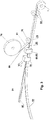
- a soft foam in the form of a wound first foam web 20 is provided on a first roll 10.
- the soft foam is provided on the first roll 10 in long lengths of up to 200 m, preferably between 5 and 100 m, more preferably between 10 and 60 m.
- All known open-cell, mixed-cell or closed-cell soft foams made of, for example, polyurethane, polyethylene, polyvinyl chloride or polypropylene, which reset after compression, can be used as foams.
- the first foam sheet 20 can be impregnated before further processing, but is preferably not yet impregnated.
- the foam web 20 can be transported and processed particularly well.
- the foam sheet 20 is usually located on the first roller 10 in a non-compressed or only slightly compressed state. It is also possible for the foam sheet 20 to be in a compressed state on the first roll 10, but after unwinding from the first roll 10, a timely resetting of the foam material in the process sequence must be ensured.
- the width of the foam sheet 20 is usually between 1 cm and 5 m, preferably between 1.0 m and 1.5 m.
- the height of the foam sheet 20 in the relaxed state is usually between 5 and 150 mm, more preferably between 10 and 80 mm.
- first foam webs 20 that are not wound on a first roll 10, but this requires a larger staging space.
- the first foam web 20 After unwinding from the first roll 10, the first foam web 20 is moved along a first conveying direction, which is indicated by the arrow V1. Subsequently, a film web 16 is applied to the top 21 of the first foam web 20 so as to form a laminated foam web 34.
- a film web 16 is applied to the top 21 of the first foam web 20 so as to form a laminated foam web 34.
- an adhesive tape web and / or a layer of an adhesive-like liquid medium can also be applied to the foam web 20.
- the film web 16 is provided on a film supply roll 26.
- the film web 16 and / or the adhesive tape web and / or the adhesive-like liquid medium is preferably applied from above to the top 21 of the foam web 20. This is usually done in the area of a first connection unit, which is represented schematically by the roller 28.
- the film web 16 or the adhesive tape web or the adhesive-like liquid medium should preferably adhere to the foam web, but not be laminated on or dried.
- the connecting step generally generally comprises a step of pressing the film web 16 or the adhesive tape web and the foam web 20 against one another.
- an adhesive-like liquid medium this is preferably applied to the foam web 20 by means of nozzles (eg melting nozzle, flat nozzle, mixing nozzle) or by roller application (transfer roller).
- the adhesive tape web is usually provided with at least one release film which is detached from the adhesive tape web before being applied to the foam web 20.
- the film web 16 can also itself comprise a layer of an adhesive tape or a layer of a hot melt adhesive. It is also possible to apply a spray adhesive to a film web 16.
- the film web 16 and / or the adhesive tape web and / or the adhesive-like liquid medium can also be attached to the underside 22 of the foam web 20 from below.
- Another exemplary embodiment provides for the application of film webs 16 and / or the adhesive tape webs and / or the adhesive-like liquid media on the top 21 and the bottom 22 of the foam web 20.
- At least one knife 38 By means of at least one knife 38, preferably a plurality of parallel knives 38, at least one through cut 40, preferably a plurality of parallel through cuts 40, is introduced into the laminated foam web 34 in the longitudinal direction of the laminated foam web 34, preferably parallel to the longitudinal edges 23 of the laminated foam web 34 ,
- the longitudinal edges 23 are the edges of the laminated foam web 34, which run parallel to the conveying direction V1 and orthogonal to the axial direction of the first roll 10.
- all other methods known to the person skilled in the art for cutting through foam sheets 20 can be used, such as, for example, cutting through saws, heated wires, laser cutting or water jet cutting.
- the continuous cuts 40 produce a plurality of first foam strips 50, which are provided with a film strip 24 and / or an adhesive tape strip and / or an adhesive-like liquid medium.
- the first foam strips 50 produced by the at least one cut 40 can have a different width, but they are preferably of the same width.
- the width of a foam strip 50 is between 5 mm and 30 cm, preferably between 1 and 12 cm.
- the first foam strips 50 can be wound onto a supply roll (not shown) at this point in order to move them for further processing and thus shorten the length of the entire production line, or they can be fed directly to further processing. All in all By using supply rolls as a buffer, the number of successive steps in a production line can be varied and thus the length of the individual sections of the production line can be adjusted according to the prevailing space conditions.
- the first foam sheet 20 is first cut into foam strips 50 and the individual foam strips 50 are then equipped with the film strips 24 and / or adhesive tape strips and / or the adhesive-like liquid medium.
- the film strips 24 and / or adhesive tape strips and / or the layer of the adhesive-like liquid medium can also only extend over part of a side surface of the foam strips 50.
- a film strip 24 can be arranged over several side surfaces.
- FIG. 2 An example of the optional process for producing second foam strips 60 is shown.
- a second foam sheet 58 made of soft foam is provided on a second roll 55, preferably uncompressed. After unwinding from the second roll 55, the second foam web 58 is moved along a second conveying direction V2. The same applies to the type of foam as to the foam of the first foam sheet 20.
- At least one knife 56 By means of at least one knife 56, preferably several parallel knives 56, at least one continuous cut 59, preferably several parallel continuous cuts 59, is made in the second foam web 58 in a direction parallel to the longitudinal edges of the foam web 58.
- the at least one continuous cut 59 thus produces a plurality of second foam strips 60.
- all other methods known to the person skilled in the art for severing foam webs can be used, for example severing by sawing, heated wires, laser cutting or water jet cutting.
- the second foam strips 60 can be wound up to form a supply roll (not shown) or can be fed directly to further processing.
- the second foam strips 60 can also be provided individually.
- the second foam strips 60 can have a film strip 24 on at least one side surface and / or an adhesive tape strip and / or an adhesive-like liquid medium.
- Fig. 3 shows essential steps of the first embodiment of the manufacturing method according to the invention, which is based on the steps Fig. 1 or 2 can connect.
- the first foam strips 50 provided with at least one film strip 24 and / or adhesive tape strips have already been pre-assembled, for example at another location or by another manufacturer, and only in this within the scope of the method according to the invention finished form can be used.
- a first foam strip 50 and a second foam strip 60 made of soft foam are brought together in such a way that a foam barrier layer web 70 is formed, in which a barrier layer 30 is arranged between the adjacent foam strips 50, 60.
- the foam strip 50 is preferably rotated 90 degrees about its longitudinal axis by means of a suitable deflection device, the longitudinal axis extending along a third conveying direction V3.
- a suitable deflection device e.g., the film strips 24 and / or the adhesive tape strips and / or the layer of the adhesive-like liquid medium is then located on a side surface of the foam strip 50 facing the foam strip 60.
- the first foam strip 50 and the second foam strip 60 become at the latest from the point of merging moved in the conveying direction V3.
- a plurality of first foam strips 50 can also be brought together with one or more second foam strips 60, or a plurality of second foam strips 60 with one or more first foam strips 50.
- the at least one first foam strip 50 can also be provided such that no rotation of the first foam strip 50 is necessary is.
- the at least one second foam strip 60 can be provided such that no rotation of the first foam strip 50 is necessary. It is always important that each side surface of the first foam strip 50 provided with a film strip 24 and / or an adhesive tape strip and / or an adhesive-like liquid medium faces the adjacent foam strip 50, 60.
- connection of the foam strips 50, 60 may require additional measures in addition to the merging of the foam strips 50, 60.
- a connection unit 36 can be provided, in which a step of applying heat and / or a step of pressing the foam strips 50, 60 together takes place.
- a possible embodiment of the connection unit 36 is described below with reference to FIG Fig. 5 described in more detail.
- a barrier layer 30 is formed from the film strip 24 and / or the adhesive tape strip and / or the adhesive-like liquid medium.
- the foam barrier layer web 70 can now be impregnated, for example, for a delayed reset.
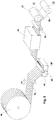
- an impregnation unit 44 with subsequent drying unit 49 is suitable, as below with reference to FIG Fig. 6 described in more detail.
- the impregnation can also take place at other points in the manufacturing process or can be omitted.
- a common adhesive layer 80 is applied to all foam strips 50, 60 of the foam barrier layer sheet 70.
- the common adhesive layer 80 is applied to a surface of the foam barrier layer web 70 that runs perpendicular to the at least one barrier layer 30.
- the adhesive layer 80 is preferably provided on a supply roll 76 and is applied to the foam barrier layer web 70 in the area of an application station, shown schematically here by the roller 78, and is preferably pressed or rolled there.
- the use of double-sided adhesive tape as adhesive layer 80 is particularly suitable. This has the advantage that it is easy to apply to the foam barrier layer web 70 and thus at the same time provides an adhesive surface on the side facing away from the foam barrier layer web 70 by means of which the sealing tape 2 can be connected to a frame profile of a window during assembly. This second adhesive surface of the double-sided adhesive tape on the foam barrier layer web 70 opposite side is first laminated with a release film 81 to avoid sticking during further processing.
- the adhesive layer 80 can also contain textile fabrics or nonwoven layers.
- the common adhesive layer 80 After the common adhesive layer 80 has been applied to all foam strips 50, 60 of the foam barrier layer web 70, the latter is compressed and wound up to form a sealing tape roll 1.
- a sealing tape roll For example, one or more pairs of compression rollers 84 may be used for compression.
- a compression roller (not shown) can interact with the sealing tape roll directly when the sealing tape 2 is wound onto the sealing tape roll 1.
- two adhesive layers 80 can also be applied on opposite sides of the foam barrier layer web 70.
- a foam barrier layer web 70 comprising a plurality of foam strips 50, 60 and barrier layers 30 is compressed after the application of a common adhesive layer 80 to form a wide roll (not shown), which is then by means of at least one knife or at least one Saw to seal tape rolls 1 desired width can be cut, as below with reference to Fig. 7 is described in more detail.
- the conveying directions V1, V2 and V3 can be identical or different from one another.
- foam strips 12 can, like the production of the foam strips 60 in Fig. 2 respectively.
- the foam strips 12 can have a different width, but they are preferably of the same width.
- the width of a foam strip 12 is preferably between 5 and 150 mm, more preferably between 10 and 80 mm.
- each film strip 24 or adhesive tape strip is preferably provided on a spool 18 or roll and is preferably introduced into the intermediate space via suitable guide elements.
- Each spool 18 can be arranged in any position relative to the foam strips 12, with each film strip 24 or adhesive tape strip always being introduced into the corresponding intermediate space essentially in the conveying direction V1.
- Deflection elements for example deflection shoulders or deflection rollers, can also be used. It is also conceivable to provide a film web or adhesive tape web (preferably in the form of a roll) and cut it lengthways into individual film strips 24 or adhesive tape strips before these are introduced into the spaces between the foam strips 12.
- Adhesive tape strips are usually provided with at least one peel-off film which is detached from the adhesive tape strip before being inserted into the space.
- each spool 18 in such a way that the film strip 24 or adhesive tape strip can be introduced into the corresponding intermediate space without being deflected.
- the connecting step generally comprises generally a step of applying heat and / or a step of pressing the foam strips 12 together.
- the connection to the foam strips 12 in the connecting unit 36 is preferably carried out by lamination.
- the film strip 24 can itself comprise one or more strips of adhesive tape or a solid layer of hot melt adhesive.
- an adhesive-like liquid medium is introduced into the spaces between the foam strips 12 by means of nozzles (for example melting nozzle, flat nozzle, mixing nozzle) or by roller application (transfer roller).
- nozzles for example melting nozzle, flat nozzle, mixing nozzle
- roller application transfer roller
- a connection of the foam strips 12 can then take place, preferably in the connecting unit 36, the adhesive generally being solidified.
- the connection of the foam strips 12 will usually again comprise a step of applying heat and / or a step of pressing the foam strips 12 together. It is also possible to according to a film strip 24 Fig. 4 to apply a spray adhesive.
- a foam barrier layer web 70 is produced, which has at least one barrier layer 30, which can be attributed to the film strip 24, the adhesive tape strip and / or the adhesive-like liquid medium.
- the connecting unit 36 preferably comprises a pair of pressure rollers 41, which are arranged on both narrow sides of the foam barrier layer web 70 and press the individual foam strips 12 against one another.
- the pressure rollers 41 are preferably each rotatably mounted about a vertical axis, the direction of rotation of the two pressure rollers 41 being in opposite directions.
- a pair of pull rollers 42 are also disposed in the connection unit 36, which extend across the width of the foam barrier layer web 70 and receive the foam barrier layer web 70 in a nip.
- the two pulling rollers 42 are each driven in opposite directions about a horizontal axis and thus pull the foam barrier layer web 70 through the connecting unit 36.
- Such pairs of pulling rollers 42 can also be used at other points in the manufacturing process.
- the pull rollers 42 can also be arranged upstream of the pressure rollers 41 in the connecting unit 36.
- the connection unit 36 preferably also comprises a heating device 43 which is shown in FIG Fig. 5 is only hinted at.
- the heater 43 may preferably include a housing that surrounds the foam barrier sheet 70.
- the heating device 43 can be designed for all possible types of heating.
- the heater 43 can be used in combination with the pressure rollers 41. It is also possible, only to provide the heating device 43 or only the pressure rollers 41 in the connecting unit 36.
- the heating device 43 can also be designed to firmly connect only the upper and lower edge regions of the foam barrier layer web 70 to one another by adjusting the temperature and / or duration of the heating accordingly.
- each barrier layer 30 is preferably to reduce or prevent the passage of air and / or water vapor. This also applies to all other exemplary embodiments.
- the foam barrier layer web 70 can be wound onto a supply roll. However, it is also possible to continuously feed the foam barrier layer web 70 to the further processing steps. As a result, the number of successive steps in a production line can be varied and thus the length of the individual sections of the production line can be adjusted according to the prevailing space conditions.
- the intermediate roller 57 can already be made at this point Fig. 7 or even directly the end product, the sealing tape roll 1.
- the foam barrier layer web 70 previously wound on a supply roll 40 is first unwound again.
- the foam barrier layer web 70 is passed through an impregnation unit 44 in a next step along a second conveying direction V2, which may be identical or different to V1 depending on the arrangement of the sections of the production line.
- Two rollers 45 guide the foam barrier layer web 70 into a bath of a suitable impregnate 48 and the foam soaks up with the impregnate.
- Usual impregnates and methods for impregnating foams are known to the person skilled in the art.
- the foam barrier layer web 70 is preferably compressed between the rollers 45 in order to promote the absorption of the impregnate 48 by the subsequent resetting of the foam.
- the impregnated foam barrier layer web 70 is dried in a drying unit 49.
- the impregnated unit is in this Foam barrier layer web 70 is dried in a known manner, for example by a heating fan or radiant heater.
- the foam barrier layer web 70 is then rolled up to an intermediate roller 57, preferably using compression rollers 51, 52. It may be sufficient if only one compression roller 51 is used directly at the transition to the intermediate roller 57, or a pair of compression rollers 52 may be used beforehand to compress the foam barrier sheet 70. In the example shown, both options are used in combination.
- the foam barrier layer web 70 is present on the intermediate roller 57 in the highly compressed state.
- the drying unit 49 after the impregnation unit 44 can also function as a heating device for firmly connecting all elements of the foam barrier layer web 70 if no heating device 43 has been used previously. In this way, a heating process could be omitted. This also applies to the embodiment of FIG Fig. 3 ,
- an adhesive layer 80 for example a double-sided adhesive tape laminated on one side with a release film, is preferably applied to the foam barrier layer web 70.
- the adhesive layer 80 is in turn mounted on a supply roll 76 or supply spool and is pulled off this.
- the adhesive layer 80 is preferably applied to the foam barrier layer web 70 simultaneously with the winding of the foam barrier layer web 70 to the intermediate roller 57, the compression roller 51 generating the pressure for connecting the adhesive layer 80 and the foam barrier layer web 70.
- the foam can also be impregnated at other positions in the production process.
- the impregnation of the foam can be dispensed with completely or can have been done before the foam strips 12 are provided.
- the impregnation of the foam takes place after the introduction of each film strip 24 or adhesive tape strip into the space between two adjacent foam strips 12, since each film strip 24 or adhesive tape strip adheres better to a non-impregnated foam and is therefore easier to connect to it.
- the intermediate roller 57 is severed according to the variant of the second exemplary embodiment of the method according to the invention at one or more points in the axial direction in order to produce a plurality of sealing tape rollers 1 that are less wide than the intermediate roller 57.
- the intermediate roller is preferably severed 57 carried out by means of one or more parallel saws 72. In Fig. 7 only one saw 72 is shown, and a further parallel section for severing the intermediate roller 57 is indicated by dashed lines.
- Other suitable methods of cutting can also be used here (for example knives, heated wires, laser cutting, water jet cutting).
- the intermediate roller 57 is cut into sealing tape rolls 1 such that foam strips 12 and the at least one barrier layer 30 alternate in the axial direction of the sealing tape roll 1.
- Each radially extending barrier layer 30 is received in a sealing tape roll 1 between two foam strips 12, as a result of which the sealing tape 2 has an increased seal against drafts and / or vapor diffusion, and each barrier layer 30 is simultaneously protected against external damage.
- the double-sided adhesive layer 80 which is preferably present and is laminated with a release film is not shown here.
- sealing tape rolls 1 are produced with exactly one barrier layer 30. Sealing tape rolls 1 with a plurality of inner barrier layers 30 can also be produced. In this case, the barrier layers 30 of a sealing tape 2 can have different vapor diffusion tightness. Likewise, for the formation of the barrier layers 30, foil strips 24 (or adhesive materials) can be used, the vapor diffusion tightness of which adapts variably to the ambient conditions.
- the step of cutting the intermediate roll 57 into individual sealing tape rolls 1 can also be omitted if the entire intermediate roll 57 is already used as a sealing tape roll 1. In this case, it may also be useful to nevertheless separate the edge regions of the intermediate roller 57 in the sense of a smoother outer surface of the sealing tape roll 1. Otherwise, the sealing tape roll 1 is manufactured, for example, as in FIG Fig. 3 shown.
- Fig. 8 shows a further alternative possibility of the final processing of the foam barrier layer web 70 for the production of sealing tape rolls 1.
- the variant shown on the right can also use a or several knives 66 or saws in the area of at least one foam strip 12 are severed in the longitudinal direction.
- at least one cut 68 is inserted into the foam barrier layer web 70, as a result of which at least two foam barrier layer strips 69 are produced.
- Each foam barrier layer strip 69 can then be wound up into a finished sealing tape roll 1.
- a double-sided adhesive layer 80 provided with a release film is preferably applied as in FIG Fig. 6 (in Fig. 8 not shown). In this way the in Fig. 7 illustrated step of dividing an intermediate roller 57 is omitted.
- Compression rollers 52 can preferably also be used here for pre-compression of the individual foam barrier layer strips 69.
- the two in 1 to 3 or 4 to 7 described variants differ only in the production of the foam barrier layer web 70. Subsequently, all further processing steps can be carried out identically. With both exemplary embodiments, wider intermediate rolls 57 can be produced, which are then divided into individual sealing tape rolls 1 (see Fig. 7 ). Likewise, narrow sealing tape rolls 1 can be produced directly with both exemplary embodiments, without a wide intermediate roll 57 being produced (see Fig. 3 ). Even the variant Fig. 8 is possible with both embodiments.
- all foam webs, foam strips, foam barrier layer webs or foam barrier layer strips are preferably moved forward by rolling, particularly preferably by pairs of rollers moving in opposite directions. Treadmills can also be used. Such means of transportation can also be used for the film strips, film webs, adhesive tape strips or adhesive tape webs.
- the heating devices mentioned in the exemplary embodiments are usually designed as warm air blowers.
- radiation heating can also be used, for example by means of infrared heating or microwave heating.
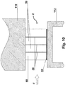
- Fig. 9 shows an installation situation of the sealing tape 2 unwound from a sealing tape roll 1 according to the invention.
- the sealing tape 2 For installation, the sealing tape 2 must first be unwound from the sealing tape roll 1 and cut into strips of any length. Usually the Length of the sealing tape strips adapted to the outer contours of a window frame or a door frame to be sealed.
- the sealing tape 2 is then preferably attached to the window frame 112 or door frame by means of the adhesive layer 80 or by means of other adhesive layers, adhesive tapes or other suitable means.
- the sealing tape 2 is received between a window frame 112 and a masonry 110 in order to seal the joint between them.
- the illustrated sealing tape 2 in this case comprises a first foam strip 50, which is provided with a barrier layer 30, and a second foam strip 60.
- the barrier layer 30 is received in a protective manner between the foam strips 50, 60, causing damage during storage, transport and the Assembly of the sealing tape roll 1 or the sealing tape 2 can be avoided.
- the sealing tape 2 is to be installed in such a way that at least one barrier layer 30 runs from the window frame 112 to the masonry 110 and thus essentially orthogonally to a functional direction F of the sealing tape 2.
- the functional direction F extends parallel to the surfaces of the window frame 112 and the masonry 110 forming the joint to be sealed from an outside of the room (in Fig. 9 left) to an inside of the room (in Fig. 9 right). In this way, a reliable seal against drafts and vapor diffusion can be guaranteed.
- the first foam strip 50 can consist of a different foam material than the second foam strip 60.
- the first foam strips 50 and the second foam strips 60 can be impregnated with different impregnate or only the first foam strips 50 or only that second foam strip 60 may be impregnated.
- the first foam strips 50 can have a different color than the second foam strips 60. In this way, for example, the preferred installation direction of the sealing tape 2 can be identified.
- any number of barrier layers 30 in the sealing tape 2 is possible.
- different widths and / or heights of the first foam strips 50 and / or different widths and / or heights of the second foam strips 60 are also conceivable, even within the same sealing tape 2.
- the first foam strip (s) 50 can also have a different width and / or or have height than the second foam strip or strips 60.
- the width of the sealing tape 2 is usually between 5 mm and 20 cm, preferably between 1 cm and 12 cm. In the relaxed state, the sealing tape 2 generally has a height of between 5 mm and 30 cm, preferably between 1 and 12 cm.
- FIG. 9 The exemplary embodiment shown forms exactly one first foam strip 50 together with exactly one second foam strip 60 the foam barrier layer web 70, which is wound up to form the sealing tape roll 1.
- the foam barrier layer web 70 which is wound up to form the sealing tape roll 1.
- first foam strips 50 here three first foam strips 50, brought together with exactly one second foam strip 60 to form the foam barrier layer web 70, with exactly one barrier layer 30 being applied to each first foam strip 50 and the second foam strip 60 being attached an edge of the foam barrier sheet 70 is disposed.
- the barrier layers 30 are arranged between adjacent foam strips 50, 60.
- two barrier layers of two adjacent foam strips 50, 50 or 50, 60 can be arranged directly next to one another.
- foam barrier layer sheets 70 of any type can be designed in this way, foam strips 50, 60 and barrier layers 30 preferably alternating in the direction of function F and one foam strip 50, 60 being arranged at one edge of the foam barrier layer sheet 70.
- the sealing tape 2 shown comprises three barrier layers 30 between four foam strips 82, the two outer foam strips 82 being only half as wide as the two inner foam layers 82.
- Variants of the sealing tape 2 shown can be produced with both variants of the manufacturing method according to claim 1 and claim 6.
- the reference numerals 50, 60 in Fig. 9 and 10 also stand for reference number 12. All of the aforementioned variants of the foam strips 50, 60 are also suitable for the foam strips 12, in particular different foam strips 12 in the same sealing tape can have different properties.
- a “barrier layer” 30 refers to a layer that is suitable for reducing the passage of air or the vapor diffusion through the sealing tape 2. A complete block against the passage of air or against vapor diffusion is possible, but not absolutely necessary. It may be expedient if at least one barrier layer 30 is moisture-variable in such a way that it is more diffusion-proof at high air humidity than at lower air humidity or vice versa.
- the materials that can be used for the barrier layer 30 for example DE 10 2010 055 788 A1 or on EP 2 733 271 A1 referenced, the content of which is to be included in this application.
- each barrier layer 30 is permanently elastic, so that it remains permanently elastic even after storage of the sealing tape roll 1 in the compressed state when the sealing tape 2 is reset and in the installed state of the sealing tape 2 in a joint always lies close to the joint flanks.
Description
Die vorliegende Erfindung betrifft ein Verfahren zur Herstellung einer Dichtbandrolle.The present invention relates to a method for producing a sealing tape roll.
Von Dichtbandrollen abgewickelte Dichtbänder werden üblicherweise zum Abdichten von Fugen beispielsweise zwischen einem Rahmenprofil eines Fensters oder einer Tür und einer Gebäudewand verwendet, um die Fugen gegen Luftzug und Schlagregen abzudichten. Zusätzlich vorgesehene Folien an einer Seitenfläche des Dichtbands erhöhen zudem die Dampfundurchlässigkeit desselben, siehe z.B.
Aus
Weiterhin offenbart
Der vorliegenden Erfindung liegt die Aufgabe zugrunde, ein Verfahren zur Herstellung einer Dichtbandrolle mit einer innenliegenden, radial verlaufenden Sperrschicht anzugeben, das einfach und zuverlässig ist und mit dem auch Dichtbandrollen großer Längen erzeugt werden können.The present invention has for its object to provide a method for producing a sealing tape roll with an internal, radially extending barrier layer, which is simple and reliable and with which sealing tape rolls of great lengths can also be produced.
Diese Aufgabe wird durch die Merkmale des Anspruchs 1 bzw. des Anspruchs 6 gelöst.This object is achieved by the features of
Erfindungsgemäß umfasst das Verfahren zur Herstellung einer Dichtbandrolle aus weichem, komprimiertem Schaumstoff mit mindestens einer in radialer Richtung verlaufenden Sperrschicht, die axial zwischen zwei Schichten aus Schaumstoff angeordnet ist, folgende Schritte in der angegebenen Reihenfolge:
- Bereitstellen mindestens eines ersten Schaumstoffstreifens aus weichem Schaumstoff, der an mindestens einer seiner Seitenflanken mit mindestens einem Folienstreifen, einem Klebebandstreifen und/oder einem klebstoffartigen flüssigen Medium versehen ist,
- Bereitstellen mindestens eines zweiten Schaumstoffstreifens aus weichem Schaumstoff,
- Zusammenführen und Verbinden des mindestens einen ersten Schaumstoffstreifens mit dem mindestens einen zweiten Schaumstoffstreifen derart, dass eine Schaumstoff-Sperrschicht-Bahn entsteht, bei der mindestens eine aus dem Folienstreifen, dem Klebebandstreifen und/oder dem klebstoffartigen flüssigen Medium hervorgegangene Sperrschicht zwischen aneinandergrenzenden Schaumstoffstreifen angeordnet ist; und
- (i) Aufwickeln der Schaumstoff-Sperrschicht-Bahn zu einer Dichtbandrolle, oder
- (ii) Aufwickeln der Schaumstoff-Sperrschicht-Bahn zu einer Zwischenrolle und Durchtrennen der Zwischenrolle an einer oder an mehreren Stellen in axialer Richtung, um eine Mehrzahl von Dichtbandrollen zu erzeugen, die weniger breit sind als die Zwischenrolle, oder
- (iii) Einbringen mindestens eines Schnitts in die Schaumstoff-Sperrschicht-Bahn in einer Längsrichtung der Schaumstoff-Sperrschicht-Bahn zur Bildung von Schaumstoff-Sperrschicht-Streifen und Aufwickeln der Schaumstoff-Sperrschicht-Streifen zu einzelnen Dichtbandrollen.
- Providing at least one first foam strip made of soft foam, which is provided on at least one of its side flanks with at least one film strip, an adhesive tape strip and / or an adhesive-like liquid medium,
- Providing at least one second foam strip made of soft foam,
- Bringing together and connecting the at least one first foam strip with the at least one second foam strip such that a foam barrier layer web is formed in which at least one barrier layer resulting from the film strip, the adhesive tape strip and / or the adhesive-like liquid medium is arranged between adjacent foam strips; and
- (i) winding the foam barrier sheet into a roll of sealing tape, or
- (ii) winding the foam barrier sheet into an intermediate roll and severing the intermediate roll at one or more locations in the axial direction to produce a plurality of sealing tape rolls that are less wide than the intermediate roll, or
- (iii) Making at least one cut in the foam barrier layer web in a longitudinal direction of the foam barrier layer web to form foam barrier layer strips and winding the foam barrier layer strips into individual rolls of sealing tape.
Auf diese Weise können Dichtbandrollen aus weichem, komprimiertem Schaumstoff mit mindestens einer in radialer Richtung verlaufenden Sperrschicht, die axial zwischen zwei Schichten des Schaumstoffs angeordnet ist, besonders wirtschaftlich und auch in großen Längen hergestellt werden. Zudem ist die Sperrschicht durch die Aufnahme zwischen zwei Schaumstoffstreifen vor äußerer Beschädigung während des Transports und der Montage des Dichtbands geschützt. Zudem sind die Eigenschaften des Dichtbands besonders variabel gestaltbar, da Schaumstoffstreifen beliebiger Gestaltung miteinander kombiniert werden können.In this way, sealing tape rolls made of soft, compressed foam with at least one barrier layer running in the radial direction, which is arranged axially between two layers of the foam, can be produced particularly economically and also in long lengths. In addition, the barrier layer is protected from external damage during transport and assembly of the sealing tape by the inclusion between two foam strips. In addition, the properties of the sealing tape can be designed in a particularly variable manner, since foam strips of any design can be combined with one another.
Vorzugsweise umfasst das Bereitstellen des mindestens einen ersten Schaumstoffstreifens folgende Schritte:
- Bereitstellen einer ersten Schaumstoffbahn aus einem weichen Schaumstoff;
- Aufbringen einer Folienbahn, einer Klebebandbahn und/oder einer Schicht aus einem klebstoffartigen flüssigen Medium auf mindestens die Oberseite oder die Unterseite der Schaumstoffbahn zur Erzeugung einer kaschierten Schaumstoffbahn; und
- Einbringen mindestens eines durchgängigen Schnitts in die kaschierte Schaumstoffbahn in einer Längsrichtung der kaschierten Schaumstoffbahn zur Erzeugung einer Mehrzahl von ersten Schaumstoffstreifen, die jeweils an mindestens einer ihrer Seitenflanken mit mindestens einem Folienstreifen, einem Klebebandstreifen und/oder einem klebstoffartigen flüssigen Medium versehen sind.
- Providing a first foam sheet made of a soft foam;
- Applying a film web, an adhesive tape web and / or a layer of an adhesive-like liquid medium to at least the top or the bottom of the foam web to produce a laminated foam web; and
- Introducing at least one continuous cut in the laminated foam web in a longitudinal direction of the laminated foam web to produce a plurality of first foam strips, each of which is provided with at least one film strip, an adhesive tape strip and / or an adhesive-like liquid medium on at least one of its side flanks.
Das Bereitstellen der ersten Schaumstoffbahn weist vorzugsweise folgende Schritte auf:
- Bereitstellen einer ersten Rolle mit der aufgewickelten ersten Schaumstoffbahn; und
- Abwickeln der ersten Schaumstoffbahn von der ersten Rolle.
- Providing a first roll with the wound first foam web; and
- Unwind the first foam sheet from the first roll.
Vorzugsweise ist die bereitgestellte erste Schaumstoffbahn nicht imprägniert, und das Verfahren weist folgende Schritte nach dem Schritt des Zusammenführens und Verbindens der Schaumstoffstreifen auf:
- Tränken der Schaumstoff-Sperrschicht-Bahn mit einem Imprägnat; und
- Trocknen der imprägnierten Schaumstoff-Sperrschicht-Bahn.
- Soaking the foam barrier sheet with an impregnate; and
- Drying the impregnated foam barrier sheet.
Die Sperrschicht haftet in diesem Fall besonders sicher an dem Schaumstoff.In this case, the barrier layer adheres particularly securely to the foam.
Das Einbringen des mindestens einen durchgängigen Schnitts in die kaschierte Schaumstoffbahn wird vorzugsweise mittels mindestens eines Messers oder mindestens einer Säge durchgeführt. Diese eignen sich besonders gut zum Durchtrennen der Schaumstoffbahn.The introduction of the at least one continuous cut into the laminated foam web is preferably carried out by means of at least one knife or at least one saw. These are particularly suitable for severing the foam sheet.
In einer alternativen Variante umfasst das erfindungsgemäße Verfahren zur Herstellung einer Dichtbandrolle aus weichem, komprimiertem Schaumstoff mit mindestens einer in radialer Richtung verlaufenden Sperrschicht, die axial zwischen zwei Schichten aus Schaumstoff angeordnet ist, folgende Schritte in der angegebenen Reihenfolge:
- Bereitstellen von mindestens zwei Schaumstoffstreifen aus weichem Schaumstoff,
- Zusammenführen der mindestens zwei Schaumstoffstreifen und gleichzeitig Einbringen eines Folienstreifens, eines Klebebandstreifens und/oder eines klebstoffartigen flüssigen Mediums in jeden Zwischenraum zwischen zwei benachbarten Schaumstoffstreifen;
- Verbinden aller Schaumstoffstreifen derart, dass eine Schaumstoff-Sperrschicht-Bahn entsteht, bei der mindestens eine aus dem Folienstreifen, dem Klebebandstreifen und/oder dem klebstoffartigen flüssigen Medium hervorgegangene Sperrschicht zwischen aneinandergrenzenden Schaumstoffstreifen angeordnet ist; und
- (i) Aufwickeln der Schaumstoff-Sperrschicht-Bahn zu einer Dichtbandrolle, oder
- (ii) Aufwickeln der Schaumstoff-Sperrschicht-Bahn zu einer Zwischenrolle und Durchtrennen der Zwischenrolle an einer oder an mehreren Stellen in axialer Richtung, um eine Mehrzahl von Dichtbandrollen zu erzeugen, die weniger breit sind als die Zwischenrolle, oder
- (iii) Einbringen mindestens eines Schnitts in die Schaumstoff-Sperrschicht-Bahn in einer Längsrichtung der Schaumstoff-Sperrschicht-Bahn zur Bildung von Schaumstoff-Sperrschicht-Streifen und Aufwickeln der Schaumstoff-Sperrschicht-Streifen zu einzelnen Dichtbandrollen.
- Providing at least two foam strips made of soft foam,
- Bringing together the at least two foam strips and simultaneously introducing a film strip, an adhesive tape strip and / or an adhesive-like liquid medium into each intermediate space between two adjacent foam strips;
- Connecting all foam strips in such a way that a foam barrier layer web is formed, in which at least one barrier layer resulting from the film strip, the adhesive tape strip and / or the adhesive-like liquid medium is arranged between adjacent foam strips; and
- (i) winding the foam barrier sheet into a roll of sealing tape, or
- (ii) winding the foam barrier sheet into an intermediate roll and severing the intermediate roll at one or more locations in the axial direction to produce a plurality of sealing tape rolls that are less wide than the intermediate roll, or
- (iii) Making at least one cut in the foam barrier layer web in a longitudinal direction of the foam barrier layer web to form foam barrier layer strips and winding the foam barrier layer strips into individual rolls of sealing tape.
Auch auf diese Weise können Dichtbandrollen aus weichem, komprimiertem Schaumstoff mit mindestens einer in radialer Richtung verlaufenden Sperrschicht, die axial zwischen zwei Schichten des Schaumstoffs angeordnet ist, besonders wirtschaftlich und auch in großen Längen hergestellt werden. Zudem ist die Sperrschicht durch die Aufnahme zwischen zwei Schaumstoffstreifen vor äußerer Beschädigung während des Transports und der Montage des Dichtbands geschützt. Zudem sind die Eigenschaften des Dichtbands besonders variabel gestaltbar, da Schaumstoffstreifen beliebiger Gestaltung miteinander kombiniert werden können.In this way too, sealing tape rolls made of soft, compressed foam with at least one barrier layer running in the radial direction, which is arranged axially between two layers of the foam, can be produced particularly economically and also in long lengths. In addition, the barrier layer is protected from external damage during transport and assembly of the sealing tape by the inclusion between two foam strips. The properties of the sealing tape are also special can be designed variably, since foam strips of any design can be combined with one another.
Vorzugsweise umfasst das Bereitstellen der mindestens zwei Schaumstoffstreifen folgende Schritte:
- Bereitstellen einer Rolle mit einer aufgewickelten Schaumstoffbahn;
- Abwickeln der Schaumstoffbahn von der Rolle; und
- Einbringen mindestens eines durchgängigen Schnitts in die Schaumstoffbahn in einer Längsrichtung der Schaumstoffbahn zur Erzeugung einer Mehrzahl von Schaumstoffstreifen.
- Providing a roll with a wound foam sheet;
- Unwinding the foam web from the roll; and
- Introducing at least one continuous cut into the foam web in a longitudinal direction of the foam web to produce a plurality of foam strips.
Das Einbringen jedes Folienstreifens oder Klebebandstreifens in jeden Zwischenraum zwischen zwei benachbarten Schaumstoffstreifen erfolgt vorzugsweise durch Abwickeln des Folienstreifens oder Klebebandstreifens von einer Spule oder Rolle und geeignete Führung des Folienstreifens oder Klebebandstreifens. Dadurch kann jeder Folienstreifen oder Klebebandstreifen in beliebiger Länge oberhalb, unterhalb oder seitlich der Schaumstoffstreifen bereitgestellt werden und dennoch gezielt in Förderrichtung der Schaumstoffstreifen in den Zwischenraum eingebracht werden.The introduction of each film strip or adhesive tape strip into each space between two adjacent foam strips is preferably carried out by unwinding the film strip or adhesive tape strip from a spool or roll and appropriately guiding the film strip or adhesive tape strip. As a result, each film strip or adhesive tape strip can be provided in any length above, below or to the side of the foam strips and can nevertheless be introduced into the intermediate space in a targeted manner in the conveying direction.
Vorzugsweise erfolgt das Einbringen des flüssigen klebstoffartigen Mediums in jeden Zwischenraum mittels einer Düse.The liquid adhesive-like medium is preferably introduced into each intermediate space by means of a nozzle.
Das Verbinden der Schaumstoffstreifen weist vorzugsweise den Schritt auf, jeden Folienstreifen mit einem oder beiden an den Folienstreifen angrenzenden Schaumstoffstreifen durch Laminierung zu verbinden.The connection of the foam strips preferably has the step of connecting each film strip to one or both foam strips adjacent to the film strips by lamination.
Das Verbinden aller Schaumstoffstreifen weist vorzugsweise den Schritt auf, das flüssige klebstoffartige Medium zu verfestigen.The connection of all foam strips preferably has the step of solidifying the liquid adhesive-like medium.
Das Verbinden aller Schaumstoffstreifen umfasst vorzugsweise den Schritt der Wärmeaufbringung.Joining all of the foam strips preferably includes the step of applying heat.
Das Verbinden aller Schaumstoffstreifen umfasst vorzugsweise den Schritt, die Schaumstoffstreifen aneinander zu drücken.Joining all of the foam strips preferably includes the step of pressing the foam strips together.
Bei Alternative (ii) wird das Durchtrennen der Zwischenrolle vorzugsweise mittels Sägen durchgeführt.In alternative (ii), the intermediate roll is preferably cut by sawing.
Vorzugsweise wird eine beidseitig klebende Klebeschicht auf alle Schaumstoffstreifen der Schaumstoff-Sperrschicht-Bahn auf einer Fläche, die senkrecht zu der mindestens einen Sperrschicht verläuft, aufgebracht, wobei die Klebeschicht auf ihrer den Schaumstoffstreifen abgewandten Seite mit einer Abziehfolie kaschiert ist. Somit kann der doppelseitige Klebestreifen unmittelbar zur Anbringung des Dichtbands an einem Rahmenprofil des Fensters verwendet werden.Preferably, a double-sided adhesive layer is applied to all foam strips of the foam barrier layer web on a surface that is perpendicular to the at least one barrier layer, the adhesive layer being laminated on its side facing away from the foam strips with a release film. Thus, the double-sided adhesive strip can be used directly to attach the sealing tape to a frame profile of the window.
Weitere Merkmale und Vorteile der vorliegenden Erfindung ergeben sich aus der nachfolgenden Beschreibung unter Bezugnahme auf die Zeichnungen.
- Fig. 1
- zeigt beispielhaft den Ablauf der Herstellung von mit einem Folienstreifen versehenen ersten Schaumstoffstreifen als optionalen Teil einer ersten Ausführungsform des erfindungsgemäßen Verfahrens zur Herstellung einer Dichtbandrolle in schematischer Perspektivansicht;
- Fig. 2
- zeigt beispielhaft den Ablauf der Herstellung von zweiten Schaumstoffstreifen als optionalen Teil der ersten Ausführungsform des erfindungsgemäßen Verfahrens in schematischer Perspektivansicht;
- Fig. 3
- zeigt schematisch wesentliche Schritte bei der ersten Ausführungsform des erfindungsgemäßen Verfahrens zur Herstellung einer Dichtbandrolle in schematischer Perspektivansicht;
- Fig. 4
- zeigt beispielhaft den Ablauf nach einem zweiten Ausführungsbeispiel des erfindungsgemäßen Verfahrens in einem ersten Abschnitt einer für das Verfahren geeigneten Vorrichtung in schematischer Perspektivansicht;
- Fig. 5
- zeigt eine schematische Detailansicht der Verbindungseinheit aus
Fig. 3 oder4 ; - Fig. 6
- zeigt den Ablauf nach dem zweiten Ausführungsbeispiel des erfindungsgemäßen Verfahrens aus
Fig. 4 in einem zweiten Abschnitt einer für das Verfahren geeigneten Vorrichtung in schematischer Perspektivansicht; - Fig. 7
- zeigt den Schritt des Durchtrennens der Zwischenrolle gemäß einer Alternative des erfindungsgemäßen Verfahrens in schematischer Perspektivansicht;
- Fig. 8
- zeigt die finalen Schritte eines alternativen Ausführungsbeispiels des erfindungsgemäßen Verfahrens in schematischer Perspektivansicht;
- Fig. 9
- zeigt eine Einbausituation einer Ausführungsform des erfindungsgemäß hergestellten Dichtbands in einer schematischen Querschnittsansicht;
- Fig. 10
- zeigt eine Einbausituation einer weiteren Ausführungsform des erfindungsgemäß hergestellten Dichtbands in einer schematischen Querschnittsansicht; und
- Fig. 11
- zeigt eine Einbausituation einer weiteren Ausführungsform des erfindungsgemäß hergestellten Dichtbands in einer schematischen Querschnittsansicht.
- Fig. 1
- shows, by way of example, the process of producing first foam strips provided with a film strip as an optional part of a first embodiment of the method according to the invention for producing a roll of sealing tape in a schematic perspective view;
- Fig. 2
- shows an example of the process of producing second foam strips as an optional part of the first embodiment of the method according to the invention in a schematic perspective view;
- Fig. 3
- schematically shows essential steps in the first embodiment of the method according to the invention for producing a sealing tape roll in a schematic perspective view;
- Fig. 4
- shows an example of the sequence according to a second embodiment of the method according to the invention in a first section of a device suitable for the method in a schematic perspective view;
- Fig. 5
- shows a schematic detailed view of the connection unit from
Fig. 3 or4 ; - Fig. 6
- shows the sequence according to the second embodiment of the method according to the invention
Fig. 4 in a second section of a device suitable for the method in a schematic perspective view; - Fig. 7
- shows the step of severing the intermediate roll according to an alternative of the inventive method in a schematic perspective view;
- Fig. 8
- shows the final steps of an alternative embodiment of the method according to the invention in a schematic perspective view;
- Fig. 9
- shows an installation situation of an embodiment of the sealing tape produced according to the invention in a schematic cross-sectional view;
- Fig. 10
- shows an installation situation of a further embodiment of the sealing tape produced according to the invention in a schematic cross-sectional view; and
- Fig. 11
- shows an installation situation of a further embodiment of the sealing tape produced according to the invention in a schematic cross-sectional view.
In
Durch die Bereitstellung auf der ersten Rolle 10 kann die Schaumstoffbahn 20 besonders gut transportiert und verarbeitet werden. In der Regel befindet sich die Schaumstoffbahn 20 auf der ersten Rolle 10 in einem nicht oder nur geringfügig komprimierten Zustand. Es ist auch möglich, dass sich die Schaumstoffbahn 20 auf der ersten Rolle 10 in einem komprimierten Zustand befindet, allerdings muss dann nach dem Abwickeln von der ersten Rolle 10 eine rechtzeitige Rückstellung des Schaumstoffmaterials im Prozessablauf sichergestellt sein. Die Breite der Schaumstoffbahn 20 liegt üblicherweise zwischen 1 cm und 5 m, vorzugsweise zwischen 1,0 m und 1,5 m. Die Höhe der Schaumstoffbahn 20 beträgt im entspannten Zustand üblicherweise zwischen 5 und 150 mm, mehr bevorzugt zwischen 10 und 80 mm.By providing it on the
Alternativ ist es ebenso möglich, einzelne erste Schaumstoffbahnen 20 bereitzustellen, die nicht auf einer ersten Rolle 10 aufgewickelt sind, wodurch jedoch ein größerer Bereitstellungsraum benötigt wird.Alternatively, it is also possible to provide individual
Nach dem Abwickeln von der ersten Rolle 10 wird die erste Schaumstoffbahn 20 entlang einer ersten Förderrichtung bewegt, die durch den Pfeil V1 gekennzeichnet ist. Anschließend wird eine Folienbahn 16 auf die Oberseite 21 der ersten Schaumstoffbahn 20 aufgebracht, um so eine kaschierte Schaumstoffbahn 34 zu bilden. Anstelle der in
In der in
Die Klebebandbahn wird in der Regel mit mindestens einer Abziehfolie bereitgestellt, die vor dem Aufbringen auf die Schaumstoffbahn 20 von der Klebebandbahn abgelöst wird.The adhesive tape web is usually provided with at least one release film which is detached from the adhesive tape web before being applied to the
Die Folienbahn 16 kann auch selbst eine Schicht eines Klebebands oder eine Schicht eines Schmelzklebers umfassen. Es ist auch möglich, auf eine Folienbahn 16 einen Sprühkleber aufzubringen.The
In alternativen Ausführungsbeispielen kann die Folienbahn 16 und/oder die Klebebandbahn und/oder das klebstoffartige flüssige Medium auch von unten an der Unterseite 22 der Schaumstoffbahn 20 angebracht werden. Ein weiteres Ausführungsbeispiel sieht das Aufbringen von Folienbahnen 16 und/oder die Klebebandbahnen und/oder das klebstoffartigen flüssigen Medien auf der Oberseite 21 und der Unterseite 22 der Schaumstoffbahn 20 vor.In alternative exemplary embodiments, the
Mittels mindestens eines Messers 38, vorzugsweise mehrerer paralleler Messer 38, wird mindestens ein durchgängiger Schnitt 40, vorzugsweise mehrere parallele durchgängige Schnitte 40, in die kaschierte Schaumstoffbahn 34 in Längsrichtung der kaschierten Schaumstoffbahn 34, vorzugsweise parallel zu den Längskanten 23 der kaschierten Schaumstoffbahn 34, eingebracht. Die Längskanten 23 sind dabei die Kanten der kaschierten Schaumstoffbahn 34, die parallel zur Förderrichtung V1 und orthogonal zur axialen Richtung der ersten Rolle 10 verlaufen. Zum Einbringen des mindestens einen durchgängigen Schnitts 40 in die Schaumstoffbahn 20 können neben den Messern 38 alle anderen dem Fachmann bekannten Verfahren zum Durchtrennen von Schaumstoffbahnen 20 verwendet werden, wie zum Beispiel Durchtrennen durch Sägen, beheizte Drähte, Laserschneiden oder Wasserstrahlschneiden.By means of at least one
Die durchgängigen Schnitte 40 erzeugen eine Mehrzahl von ersten Schaumstoffstreifen 50, die mit einem Folienstreifen 24 und/oder einem Klebebandstreifen und/oder einem klebstoffartigen flüssigen Medium versehen sind. Die durch den mindestens einen Schnitt 40 erzeugten ersten Schaumstoffstreifen 50 können eine unterschiedliche Breite aufweisen, vorzugsweise sind sie aber gleich breit. Die Breite eines Schaumstoffstreifens 50 liegt zwischen 5 mm und 30 cm, vorzugsweise zwischen 1 und 12 cm. Die ersten Schaumstoffstreifen 50 können an dieser Stelle auf eine Vorratsrolle (nicht dargestellt) aufgewickelt werden, um sie zur weiteren Bearbeitung zu versetzen und somit die Länge der gesamten Produktionslinie zu verkürzen, oder können der weiteren Verarbeitung direkt zugeführt werden. Insgesamt kann durch die Verwendung von Vorratsrollen als Zwischenspeicher die Anzahl der in einer Produktionslinie aufeinanderfolgenden Schritte variiert und somit die Länge der einzelnen Teilabschnitte der Produktionslinie entsprechend den vorherrschenden Platzverhältnissen angepasst werden.The
Es ist ebenso denkbar, dass die erste Schaumstoffbahn 20 zuerst in Schaumstoffstreifen 50 geschnitten wird und die einzelnen Schaumstoffstreifen 50 anschließend mit den Folienstreifen 24 und/oder Klebebandstreifen und/oder dem klebstoffartigen flüssigen Medium ausgerüstet werden. In diesem Fall können sich die Folienstreifen 24 und/oder Klebebandstreifen und/oder die Schicht des klebstoffartigen flüssigen Mediums auch nur über einen Teil einer Seitenfläche der Schaumstoffstreifen 50 erstrecken. Ebenso kann ein Folienstreifen 24 über mehrere Seitenflächen angeordnet sein.It is also conceivable that the
In
Mittels mindestens eines Messers 56, vorzugsweise mehrerer paralleler Messer 56, wird mindestens ein durchgängiger Schnitt 59, vorzugsweise mehrere parallele durchgängige Schnitte 59, in die zweite Schaumstoffbahn 58 in einer Richtung parallel zu den Längskanten der Schaumstoffbahn 58 eingebracht. Der mindestens eine durchgängige Schnitt 59 erzeugt so eine Mehrzahl von zweiten Schaumstoffstreifen 60. Auch hier können neben den Messern 56 alle anderen dem Fachmann bekannten Verfahren zum Durchtrennen von Schaumstoffbahnen angewendet werden, beispielsweise Durchtrennen durch Sägen, beheizte Drähte, Laserschneiden oder Wasserstrahlschneiden. Ebenso ist es auch hier möglich, die zweite Schaumstoffbahn 58 ohne Aufwicklung zu einer zweiten Rolle 55 bereitzustellen. Die zweiten Schaumstoffstreifen 60 können an dieser Stelle zu einer Vorratsrolle (nicht dargestellt) aufgewickelt werden oder direkt der weiteren Verarbeitung zugeführt werden. Schließlich können die zweiten Schaumstoffstreifen 60 auch einzeln bereitgestellt werden. Außerdem können die zweiten Schaumstoffstreifen 60 ebenso wie die ersten Schaumstoffstreifen 50 auf mindestens einer Seitenfläche mit einem Folienstreifen 24 und/oder einem Klebebandstreifen und/oder einem klebstoffartigen flüssigen Medium versehen sein.By means of at least one
In dem in
Das Verbinden der Schaumstoffstreifen 50, 60 kann neben dem Zusammenführen der Schaumstoffstreifen 50, 60 noch weitere Maßnahmen erfordern. Beispielsweise kann eine Verbindungseinheit 36 vorgesehen sein, in der ein Schritt der Wärmeaufbringung und/oder ein Schritt, die Schaumstoffstreifen 50, 60 aneinander zu drücken, erfolgt. Eine mögliche Ausgestaltung der Verbindungseinheit 36 wird weiter unten unter Bezugnahme auf
In jedem Fall wird beim Zusammenführen und Verbinden der Schaumstoffstreifen 50, 60 aus dem Folienstreifen 24 und/oder dem Klebebandstreifen und/oder dem klebstoffartigen flüssigen Medium eine Sperrschicht 30 gebildet.In any case, when the foam strips 50, 60 are brought together and connected, a
Die Schaumstoff-Sperrschicht-Bahn 70 kann nun beispielsweise zur verzögerten Rückstellung imprägniert werden. Hierzu eignet sich beispielsweise eine Imprägniereinheit 44 mit nachfolgender Trockeneinheit 49 wie unten unter Bezugnahme auf
Nach dem Zusammenführen und Verbinden des mindestens einen ersten Schaumstoffstreifens 50 mit dem mindestens einen zweiten Schaumstoffstreifen 60 zu einer Schaumstoff-Sperrschicht-Bahn 70 und dem optionalen Imprägnieren wird eine gemeinsame Klebeschicht 80 auf alle Schaumstoffstreifen 50, 60 der Schaumstoff-Sperrschicht-Bahn 70 aufgebracht. Das Aufbringen der gemeinsamen Klebeschicht 80 erfolgt auf einer Fläche der Schaumstoff-Sperrschicht-Bahn 70, die senkrecht zu der mindestens einen Sperrschicht 30 verläuft.After the at least one
Vorzugsweise ist die Klebeschicht 80 auf einer Vorratsrolle 76 bereitgestellt und wird im Bereich einer Aufbringstation, hier schematisch dargestellt durch die Walze 78, auf die Schaumstoff-Sperrschicht-Bahn 70 aufgebracht und dort vorzugsweise festgedrückt oder festgewalzt. Besonders geeignet ist die Verwendung von doppelseitigem Klebeband als Klebeschicht 80. Dieses hat den Vorteil, dass es einfach auf die Schaumstoff-Sperrschicht-Bahn 70 aufzubringen ist und somit zugleich eine Klebefläche auf der der Schaumstoff-Sperrschicht-Bahn 70 abgewandten Seite bereitgestellt wird, mittels derer das Dichtband 2 bei der Montage mit einem Rahmenprofil eines Fensters verbunden werden kann. Diese zweite Klebefläche des doppelseitigen Klebebands auf der der Schaumstoff-Sperrschicht-Bahn 70 abgewandten Seite ist zunächst mit einer Abziehfolie 81 kaschiert, um ein Verkleben während der weiteren Bearbeitung zu vermeiden. Die Klebeschicht 80 kann auch Textilgewebe oder Vliesschichten enthalten.The
Nach dem Aufbringen der gemeinsamen Klebeschicht 80 auf alle Schaumstoffstreifen 50, 60 der Schaumstoff-Sperrschicht-Bahn 70 wird diese komprimiert zu einer Dichtbandrolle 1 aufgewickelt. Für die Komprimierung kann beispielsweise ein oder mehrere Paare von Komprimierwalzen 84 verwendet werden. Alternativ oder zusätzlich kann auch eine Komprimierwalze (nicht dargestellt) direkt beim Aufwickeln des Dichtbands 2 auf die Dichtbandrolle 1 mit der Dichtbandrolle zusammenwirken.After the
Es können bei allen Ausführungsbeispielen auch zwei Klebeschichten 80 auf gegenüberliegenden Seiten der Schaumstoff-Sperrschicht-Bahn 70 aufgebracht werden.In all exemplary embodiments, two
In einem alternativen Ausführungsbeispiel wird eine Schaumstoff-Sperrschicht-Bahn 70 aus einer Vielzahl an Schaumstoffstreifen 50, 60 und Sperrschichten 30 nach dem Aufbringen einer gemeinsamen Klebeschicht 80 komprimiert zu einer breiten Rolle (nicht dargestellt) aufgewickelt, die dann mittels mindestens eines Messers oder mindestens einer Säge zu Dichtbandrollen 1 gewünschter Breite durchtrennt werden kann, wie weiter unten noch unter Bezugnahme auf
Die Förderrichtungen V1, V2 und V3 können je nach Anordnung der Teilstrecken der Produktionslinie identisch oder zueinander verschieden sein.Depending on the arrangement of the sections of the production line, the conveying directions V1, V2 and V3 can be identical or different from one another.
In
Vor den in
Eine gewünschte Zahl an einzelnen Schaumstoffstreifen 12 wird nun über geeignete Zugmittel und Führungselemente zusammengeführt. In jeden Zwischenraum zwischen zwei Schaumstoffstreifen 12 wird außerdem jeweils ein Folienstreifen 24 oder ein Klebebandstreifen eingebracht. Jeder Folienstreifen 24 oder Klebebandstreifen ist dazu vorzugsweise auf einer Spule 18 oder Rolle bereitgestellt und wird bevorzugt über geeignete Führungselemente in den Zwischenraum eingebracht. Jede Spule 18 kann in beliebiger Position zu den Schaumstoffstreifen 12 angeordnet sein, wobei jeder Folienstreifen 24 oder Klebebandstreifen stets im Wesentlichen in Förderrichtung V1 in den entsprechenden Zwischenraum eingebracht wird. Es können dabei auch Umlenkelemente, beispielsweise Umlenkschultern oder Umlenkrollen, verwendet werden. Es ist auch denkbar, eine Folienbahn oder Klebebandbahn (vorzugsweise in Rollenform) bereitzustellen und diese längs in einzelne Folienstreifen 24 oder Klebebandstreifen zu zerschneiden, bevor diese in die Zwischenräume zwischen den Schaumstoffstreifen 12 eingebracht werden.A desired number of individual foam strips 12 is then brought together using suitable traction means and guide elements. In each space between two
Klebebandstreifen werden in der Regel mit mindestens einer Abziehfolie bereitgestellt, die vordem Einfügen in den Zwischenraum vom Klebebandstreifen abgelöst wird.Adhesive tape strips are usually provided with at least one peel-off film which is detached from the adhesive tape strip before being inserted into the space.
Es ist auch denkbar, jede Spule 18 derart anzuordnen, dass der Folienstreifen 24 oder Klebebandstreifen ohne Umlenkung in den entsprechenden Zwischenraum eingebracht werden kann. Zudem ist es möglich, die Folienstreifen 24 oder Klebebandstreifen in jeder anderen geeigneten Form, beispielsweise als Streifen vorbestimmter Länge, bereitzustellen und einzubringen.It is also conceivable to arrange each
Nach dem Einbringen jedes Folienstreifens 24 oder Klebebandstreifens in den Zwischenraum zwischen zwei benachbarten Schaumstoffstreifen 12 erfolgt die Verbindung aller Folienstreifen 24 oder Klebebandstreifen (vorzugsweise bestehend aus Haftkleber) mit den zwei angrenzenden Schaumstoffstreifen 12, vorzugsweise im Bereich einer Verbindungseinheit 36. Der Verbindungsschritt umfasst in der Regel allgemein einen Schritt der Wärmeaufbringung und/oder einen Schritt, die Schaumstoffstreifen 12 aneinander zu drücken. Bei Folienstreifen 24 erfolgt die Verbindung mit den Schaumstoffstreifen 12 in der Verbindungseinheit 36 vorzugsweise durch Laminierung. Der Folienstreifen 24 kann auch selbst einen oder mehrere Klebebandstreifen oder eine feste Schicht eines Schmelzklebers umfassen.After each
Außerdem ist es möglich, dass anstelle der Folienstreifen 24 oder Klebebandstreifen ein klebstoffartiges flüssiges Medium mittels Düsen (z.B. Schmelzdüse, Flachdüse, Mischdüse) oder über Walzenauftrag (Transferwalze) in die Zwischenräume zwischen den Schaumstoffstreifen 12 eingebracht wird. Je nach Klebstoff kann anschließend, vorzugsweise in der Verbindungseinheit 36, eine Verbindung der Schaumstoffstreifen 12 stattfinden, wobei der Klebstoff in der Regel verfestigt wird. Es kommen grundsätzlich chemische und physikalische Arten der Verfestigung in Frage. Auch hier wird die Verbindung der Schaumstoffstreifen 12 in der Regel wieder einen Schritt der Wärmeaufbringung und/oder einen Schritt, die Schaumstoffstreifen 12 aneinander zu drücken, umfassen. Es ist auch möglich, auf einen Folienstreifen 24 gemäß
Grundsätzlich wird eine Schaumstoff-Sperrschicht-Bahn 70 erzeugt, die mindestens eine Sperrschicht 30 aufweist, die auf den Folienstreifen 24, den Klebebandstreifen und/oder das klebstoffartige flüssige Medium zurückzuführen ist.Basically, a foam
Eine Detailansicht einer möglichen Verbindungseinheit 36 ist in
Vorzugsweise umfasst die Verbindungseinheit 36 zudem eine Heizvorrichtung 43, die in
Die Funktion jeder Sperrschicht 30 liegt vorzugsweise in einer Reduzierung oder Verhinderung des Durchtritts von Luft und/oder Wasserdampf. Dies gilt auch für alle anderen Ausführungsbeispiele.The function of each
Hinter der Verbindungseinheit 36 kann die Schaumstoff-Sperrschicht-Bahn 70 auf eine Vorratsrolle aufgewickelt werden. Es ist aber auch möglich, die Schaumstoff-Sperrschicht-Bahn 70 kontinuierlich den weiteren Bearbeitungsschritten zuzuführen. Dadurch kann die Anzahl der in einer Produktionslinie aufeinanderfolgenden Schritte variiert und somit die Länge der einzelnen Teilabschnitte der Produktionslinie entsprechend den vorherrschenden Platzverhältnissen angepasst werden.Behind the connecting
Wenn die Schaumstoffstreifen 12 bereits vorher imprägniert sind oder das Dichtband unimprägniert bleiben soll, kann an dieser Stelle bereits die Zwischenrolle 57 aus
Falls dies nicht der Fall ist, sind in
Die Trockeneinheit 49 nach der Imprägniereinheit 44 kann in einer besonderen Ausführungsform auch als Heizvorrichtung zum festen Verbinden aller Elemente der Schaumstoff-Sperrschicht-Bahn 70 fungieren, wenn zuvor noch keine Heizvorrichtung 43 verwendet wurde. Auf diese Weise könnte ein Heizvorgang entfallen. Dies gilt auch bei der Ausführungsform der
Auf die Schaumstoff-Sperrschicht-Bahn 70 wird außerdem vorzugsweise eine Klebeschicht 80, beispielsweise ein einseitig mit einer Abziehfolie kaschiertes doppelseitiges Klebeband, aufgebracht. Die Klebeschicht 80 ist wiederum auf einer Vorratsrolle 76 oder Vorratsspule gelagert und wird von dieser abgezogen. Vorzugsweise erfolgt die Aufbringung der Klebeschicht 80 auf die Schaumstoff-Sperrschicht-Bahn 70 gleichzeitig mit der Aufwicklung der Schaumstoff-Sperrschicht-Bahn 70 zur Zwischenrolle 57, wobei die Kompressionswalze 51 den Druck zur Verbindung von Klebeschicht 80 und Schaumstoff-Sperrschicht-Bahn 70 erzeugt.In addition, an
Das Imprägnieren des Schaumstoffs kann auch an anderen Positionen des Herstellungsverfahrens erfolgen. Ebenso kann das Imprägnieren des Schaumstoffs komplett entfallen oder bereits vor dem Bereitstellen der Schaumstoffstreifen 12 geschehen sein. Vorzugsweise findet das Imprägnieren des Schaumstoffs jedoch nach dem Einbringen jedes Folienstreifens 24 oder Klebebandstreifens in den Zwischenraum zwischen zwei benachbarten Schaumstoffstreifen 12 statt, da jeder Folienstreifen 24 oder Klebebandstreifen besser an einem nicht imprägnierten Schaumstoff haftet und sich folglich besser mit diesem verbinden lässt.The foam can also be impregnated at other positions in the production process. Likewise, the impregnation of the foam can be dispensed with completely or can have been done before the foam strips 12 are provided. Preferably, however, the impregnation of the foam takes place after the introduction of each
Wie in
Die Zwischenrolle 57 wird derart in Dichtbandrollen 1 geschnitten, dass sich Schaumstoffstreifen 12 und die mindestens eine Sperrschicht 30 in axialer Richtung der Dichtbandrolle 1 abwechseln. Dabei ist in einer Dichtbandrolle 1 jede radial verlaufende Sperrschicht 30 zwischen zwei Schaumstoffstreifen 12 aufgenommen, wodurch das Dichtband 2 eine erhöhte Abdichtung gegen Luftzug und/oder Dampfdiffusion aufweist und jede Sperrschicht 30 gleichzeitig vor äußerer Beschädigung geschützt ist. Aus Gründen der Übersichtlichkeit ist die vorzugsweise vorhandene, mit einer Abziehfolie kaschierte doppelseitige Klebeschicht 80 hier nicht dargestellt.The
Im Ausführungsbeispiel der
Die beiden in
Neben den Zugkräften durch stromabwärtiges Aufwickeln werden alle Schaumstoffbahnen, Schaumstoffstreifen, Schaumstoff-Sperrschicht-Bahnen oder Schaumstoff-Sperrschicht-Streifen vorzugsweise durch Walzen, besonders bevorzugt durch Paare gegenläufig bewegter Walzen, vorwärtsbewegt. Auch Laufbänder können verwendet werden. Derartige Fortbewegungsmittel können auch für die Folienstreifen, Folienbahnen, Klebebandstreifen oder Klebebandbahnen verwendet werden.In addition to the tensile forces caused by downstream winding, all foam webs, foam strips, foam barrier layer webs or foam barrier layer strips are preferably moved forward by rolling, particularly preferably by pairs of rollers moving in opposite directions. Treadmills can also be used. Such means of transportation can also be used for the film strips, film webs, adhesive tape strips or adhesive tape webs.
Die in den Ausführungsbeispielen genannten Heizvorrichtungen sind üblicherweise als Warmluftgebläse ausgestaltet. Es kommt aber auch Strahlungserhitzung in Frage, beispielsweise mittels einer Infrarotheizung oder Mikrowellenheizung.The heating devices mentioned in the exemplary embodiments are usually designed as warm air blowers. However, radiation heating can also be used, for example by means of infrared heating or microwave heating.
In der in
Das Dichtband 2 ist so zu verbauen, dass mindestens eine Sperrschicht 30 vom Fensterrahmen 112 zum Mauerwerk 110 und somit im Wesentlichen orthogonal zu einer Funktionsrichtung F des Dichtbands 2 verläuft. Die Funktionsrichtung F erstreckt sich dabei parallel zu den die abzudichtende Fuge bildenden Flächen des Fensterrahmens 112 und des Mauerwerks 110 von einer Raumaußenseite (in
Zur weiteren Gestaltung der Dichteigenschaften des Dichtbandes 2 kann der erste Schaumstoffstreifen 50 aus einem anderen Schaumstoffmaterial bestehen als der zweite Schaumstoffstreifen 60. Ebenso können die ersten Schaumstoffstreifen 50 und die zweiten Schaumstoffstreifen 60 mit unterschiedlichem Imprägnat imprägniert sein oder auch nur die ersten Schaumstoffstreifen 50 oder nur die zweiten Schaumstoffstreifen 60 imprägniert sein. In einem weiteren Ausführungsbeispiel können die ersten Schaumstoffstreifen 50 eine andere Farbe als die zweiten Schaumstoffstreifen 60 aufweisen. Dadurch kann beispielsweise eine Kennzeichnung der bevorzugten Einbaurichtung des Dichtbands 2 erfolgen.To further design the sealing properties of the sealing
Grundsätzlich ist jede beliebige Anzahl an Sperrschichten 30 im Dichtband 2 möglich. Ebenso sind verschiedene Breiten und/oder Höhen der ersten Schaumstoffstreifen 50 und/oder verschiedene Breiten und/oder Höhen der zweiten Schaumstoffstreifen 60 denkbar, auch innerhalb desselben Dichtbandes 2. Innerhalb eines Dichtbands 2 können auch der oder die ersten Schaumstoffstreifen 50 eine andere Breite und/oder Höhe aufweisen als der oder die zweiten Schaumstoffstreifen 60. Die Breite des Dichtbands 2 liegt üblicherweise zwischen 5 mm und 20 cm, vorzugsweise zwischen 1 cm und 12 cm. Im entspannten Zustand hat das Dichtband 2 in der Regel eine Höhe von zwischen 5 mm und 30 cm, vorzugsweise zwischen 1 und 12 cm.In principle, any number of barrier layers 30 in the sealing
In dem in
In einem weiteren alternativen Ausführungsbeispiel gemäß
Ebenso ist es möglich, dass zwei Sperrschichten von zwei aneinandergrenzenden Schaumstoffstreifen 50, 50 oder 50, 60 unmittelbar nebeneinander angeordnet sind.It is also possible for two barrier layers of two adjacent foam strips 50, 50 or 50, 60 to be arranged directly next to one another.
Prinzipiell können auf diese Weise Schaumstoff-Sperrschicht-Bahnen 70 beliebiger Ausprägung gestaltet werden, wobei sich Schaumstoffstreifen 50, 60 und Sperrschichten 30 vorzugsweise in Funktionsrichtung F abwechseln und jeweils ein Schaumstoffstreifen 50, 60 an einem Rand der Schaumstoff-Sperrschicht-Bahn 70 angeordnet ist.In principle, foam
Das in
Alle in
Als "Sperrschicht" 30 wird im Rahmen dieser Anmeldung eine Schicht bezeichnet, die geeignet ist, den Durchtritt von Luft oder die Dampfdiffusion durch das Dichtband 2 zu reduzieren. Eine vollständige Sperrung gegenüber einem Durchtritt von Luft oder gegenüber Dampfdiffusion ist möglich, aber nicht zwangsläufig notwendig. Es kann zweckmäßig sein, wenn wenigstens eine Sperrschicht 30 feuchtevariabel ist derart, dass sie bei hoher Luftfeuchtigkeit diffusionsdichter ist als bei niedrigerer Luftfeuchtigkeit oder umgekehrt.In the context of this application, a “barrier layer” 30 refers to a layer that is suitable for reducing the passage of air or the vapor diffusion through the sealing
Hinsichtlich der für die Sperrschicht 30 einsetzbaren Materialien wird beispielsweise auf
Besondere Bedeutung hat neben den Eigenschaften der Verringerung oder Verhinderung der Dampfdiffusion, dass jede Sperrschicht 30 dauerelastisch ist, so dass sie auch nach Lagerung der Dichtbandrolle 1 im komprimierten Zustand bei der Rückstellung des Dichtbands 2 dauerhaft elastisch bleibt und im Einbauzustand des Dichtbandes 2 in einer Fuge jederzeit dicht an den Fugenflanken anliegt.In addition to the properties of reducing or preventing vapor diffusion, it is particularly important that each
Claims (15)
- Method for producing a sealing tape roll (1) consisting of soft, compressed foam having at least one barrier layer (30) which extends in the radial direction and which is arranged axially between two layers of foam, comprising the following steps in the order specified:- providing at least one first foam strip (50) consisting of soft foam which is provided with at least one film strip (24), an adhesive tape strip and/or an adhesive-like liquid medium on at least one of its lateral flanks,- providing at least one second foam strip (60) consisting of soft foam,- combining and connecting the at least one first foam strip (50) with and to the at least one second foam strip (60) in such a way that a foam barrier-layer web (70) results in which at least one barrier layer (30) which has resulted from the film strip (24), the adhesive tape strip and/or the adhesive-like liquid medium is arranged between foam strips (50, 60) which are adjacent to one another; and- (i) winding up the foam barrier-layer web (70) to form a sealing tape roll (1), or- (ii) winding up the foam barrier-layer web (70) to form an intermediate roll (57) and severing the intermediate roll (57) at one or more points in the axial direction in order to create a plurality of sealing tape rolls (1) which are less wide than the intermediate roll (57), or- (iii) making at least one cut (68) in the foam barrier-layer web (70) in a longitudinal direction of the foam barrier-layer web (70) to form foam barrier-layer strips (69) and winding up the foam barrier-layer strips (69) to form individual sealing tape rolls (1) .
- Method according to claim 1, characterized in that the provision of the at least one first foam strip (50) comprises the following steps:- providing a first foam web (20) consisting of a soft foam;- applying a film web (16) an adhesive tape web and/or a layer consisting of an adhesive-like liquid medium to at least the upper side (21) or the underside (22) of the foam web (20) to produce a laminated foam web (34); and- making at least one continuous cut (40) in the laminated foam web (34) in a longitudinal direction of the laminated foam web (34) to produce a plurality of first foam strips (50) which are each provided on at least one of their lateral flanks with at least one film strip (24), an adhesive tape strip and/or an adhesive-like liquid medium.
- Method according to Claim 2, characterized in that the provision of the first foam web (20) comprises the following steps:- providing a first roll (10) having the wound-up first foam web (20); and- unwinding the first foam web (20) from the first roll (10).
- Method according to Claim 2 or 3, characterized in that the first foam web (20) provided is not impregnated, and the method comprises the following steps after the step of combining and connecting the foam strips (50, 60) :- impregnating the foam barrier-layer web (70) with an impregnating substance (94); and- drying the impregnated foam barrier-layer web (70).
- Method according to one of Claims 2 to 4, characterized in that the making of the at least one continuous cut (40) in the laminated foam web (34) is carried out by means of at least one knife (38) or at least one saw.
- Method for producing a sealing tape roll (1) consisting of soft, compressed foam having at least one barrier layer (30) which extends in the radial direction and which is arranged axially between two layers of foam, comprising the following steps in the order specified:- providing at least two foam strips (12) consisting of soft foam,- combining the at least two foam strips (12) and simultaneously introducing a film strip (24), an adhesive tape strip and/or an adhesive-like liquid medium into each interspace between two adjacent foam strips (12);
connecting all of the foam strips (12) in such a manner that a foam barrier-layer web (70) results in which at least one barrier layer (30) which has resulted from the film strip (24), the adhesive tape strip and/or the adhesive-like liquid medium is arranged between foam strips (12) which are adjacent to one another; and- (i) winding up the foam barrier-layer web (70) to form a sealing tape roll (1), or- (ii) winding up the foam barrier-layer web (70) to form an intermediate roll (57) and severing the intermediate roll (57) at one or more points in the axial direction in order to create a plurality of sealing tape rolls (1) which are less wide than the intermediate roll (57), or
(iii) making at least one cut (68) in the foam barrier-layer web (70) in a longitudinal direction of the foam barrier-layer web (70) to form foam barrier-layer strips (69) and winding up the foam barrier-layer strips (69) to form individual sealing tape rolls (1). - Method according to Claim 6, characterized in that the provision of the at least two foam strips (12) comprises the following steps:- providing a roll (55) having a wound-up foam web (58) ;- unwinding the foam web (58) from the roll (55); and- making at least one continuous cut (59) in the foam web (58) in a longitudinal direction of the foam web (58) to produce a plurality of foam strips (12).
- Method according to Claim 6 or 7, characterized in that each film strip (24) or adhesive tape strip is introduced into each interspace between two adjacent foam strips (12) by unwinding the film strip (24) or adhesive tape strip from a reel (18) or roll and suitably guiding the film strip (24) or adhesive tape strip.
- Method according to Claim 6 or 7, characterized in that the liquid adhesive-like medium is introduced into each interspace by means of a nozzle.
- Method according to one of the preceding claims, characterized in that the connection of the foam strips (12, 50, 60) comprises the step of connecting each film strip (24) to one or both foam strips (12, 50, 60) adjoining the film strip (24) by lamination.
- Method according to one of the preceding claims, characterized in that the connection of all of the foam strips (12, 50, 60) comprises the step of curing the liquid adhesive-like medium.
- Method according to one of the preceding claims, characterized in that the connection of all of the foam strips (12, 50, 60) comprises the step of heat application.
- Method according to one of the preceding claims, characterized in that the connection of all of the foam strips (12, 50, 60) comprises the step of pressing the foam strips (12, 50, 60) against one another.
- Method according to one of the preceding claims, based on alternative (ii), characterized in that the intermediate roll (57) is severed by means of saws (62) .
- Method according to one of the preceding claims, characterized in that an adhesive layer (80) which adheres on both sides is applied to all of the foam strips (12, 50, 60) of the foam barrier-layer web (70) on a surface which extends perpendicular to the at least one barrier layer (30), wherein the adhesive layer (80) is laminated on its side facing away from the foam strips (12, 50, 60) with a peel-off film (81).
Priority Applications (4)
| Application Number | Priority Date | Filing Date | Title |
|---|---|---|---|
| EP14182235.3A EP2990553B1 (en) | 2014-08-26 | 2014-08-26 | Method for manufacturing a sealing tape roll |
| DK14182235.3T DK2990553T3 (en) | 2014-08-26 | 2014-08-26 | Process for making a sealing tape roll |
| PL14182235T PL2990553T3 (en) | 2014-08-26 | 2014-08-26 | Method for manufacturing a sealing tape roll |
| US14/826,258 US9938109B2 (en) | 2014-08-26 | 2015-08-14 | Method for the production of a sealing tape roll |
Applications Claiming Priority (1)
| Application Number | Priority Date | Filing Date | Title |
|---|---|---|---|
| EP14182235.3A EP2990553B1 (en) | 2014-08-26 | 2014-08-26 | Method for manufacturing a sealing tape roll |
Publications (2)
| Publication Number | Publication Date |
|---|---|
| EP2990553A1 EP2990553A1 (en) | 2016-03-02 |
| EP2990553B1 true EP2990553B1 (en) | 2020-01-22 |
Family
ID=51392149
Family Applications (1)
| Application Number | Title | Priority Date | Filing Date |
|---|---|---|---|
| EP14182235.3A Active EP2990553B1 (en) | 2014-08-26 | 2014-08-26 | Method for manufacturing a sealing tape roll |
Country Status (4)
| Country | Link |
|---|---|
| US (1) | US9938109B2 (en) |
| EP (1) | EP2990553B1 (en) |
| DK (1) | DK2990553T3 (en) |
| PL (1) | PL2990553T3 (en) |
Families Citing this family (13)
| Publication number | Priority date | Publication date | Assignee | Title |
|---|---|---|---|---|
| US20140087198A1 (en) * | 2012-09-26 | 2014-03-27 | Web Industries, Inc. | Prepreg tape slitting method and apparatus |
| DE102016114227A1 (en) * | 2016-08-01 | 2018-02-01 | Tremco Illbruck Produktion Gmbh | Method and device for producing a sealing strip |
| DE102017105323A1 (en) | 2017-03-14 | 2018-09-20 | Tremco Illbruck Produktion Gmbh | Sealing strip and method for producing a sealing strip |
| DE102017110856A1 (en) | 2017-05-18 | 2018-12-06 | tremco illbruck GmbH | Manufacturing process for sealing tape and sealing tape |
| DK3450642T3 (en) | 2017-09-01 | 2020-03-02 | Iso Chemie Gmbh | Process for making a sealing tape roll |
| CN109229559B (en) * | 2018-07-04 | 2024-03-08 | 吴付利 | Double-layer coiled film placing and rotating device |
| DE102018118854A1 (en) | 2018-08-02 | 2020-02-06 | tremco illbruck GmbH | Manufacturing process for sealing tape and sealing tape |
| EP3650608B1 (en) | 2018-11-07 | 2023-06-07 | ISO-Chemie GmbH | Method for producing a roll of sealing strip |
| EP3680304A1 (en) * | 2019-01-11 | 2020-07-15 | tremco illbruck GmbH | Sealing strip and method and device for manufacturing a sealing strip |
| DE102019100686B4 (en) | 2019-01-11 | 2022-03-10 | Tremco CPG Germany GmbH | Method and device for producing a sealing tape |
| DE102020100140A1 (en) * | 2020-01-07 | 2021-07-08 | Tremco CPG Germany GmbH | Method and device for producing a sealing tape and sealing tape |
| CN110697467B (en) * | 2019-11-01 | 2021-08-03 | 潍坊驼王实业有限公司 | Coiling mechanism of multilayer geotechnique's cloth composite forming |
| EP4200491A1 (en) * | 2020-08-24 | 2023-06-28 | Hilti Aktiengesellschaft | Method for producing multiple profiled seal sections, and profiled seal section |
Citations (15)
| Publication number | Priority date | Publication date | Assignee | Title |
|---|---|---|---|---|
| DE1635590A1 (en) | 1965-05-17 | 1971-04-22 | Du Pont | Process for the production of fibrous sheet materials |
| DE2410121A1 (en) | 1974-03-02 | 1975-09-18 | Irbit Holding Ag | Winding method for strips of elastically compressable material - intermediate lining foil return tension produces compression pressure |
| DE1784467C3 (en) | 1967-08-17 | 1976-05-20 | N.V. Asphalt-Bitumen-Onderneming Asbiton, Zwijndrecht (Niederlande) | Pre-compressed joint sealing tape, method for its manufacture and transport unit from such tapes |
| FR2309768A1 (en) * | 1975-04-28 | 1976-11-26 | Mora Alcide | Elastic jointing for expansion joints - comprises cellular material in at least two superposed layers with impermeable layer between |
| EP0072955A1 (en) | 1981-08-22 | 1983-03-02 | Irbit Holding AG | Reel-wound foam-plastic strip, preferably for sealing purposes |
| US4486990A (en) * | 1982-04-21 | 1984-12-11 | Bauch Tamil D | Removable window insulation system |
| DE4020230A1 (en) | 1989-06-30 | 1991-01-03 | Heribert Hiendl | Joint sealing strip for the building industry - with foam base contg a mixture of hydrophilic and water repellent substances |
| DE19641415A1 (en) | 1996-10-08 | 1998-04-16 | Hanno Werk Gmbh & Co Kg | Draught or weather resistant sealing strip and manufacturing process in which foam sheets are laminated |
| DE202005000873U1 (en) | 2005-01-20 | 2005-03-24 | Wirz Peter | Sealing tape for a joint between a frame and a wall material around it comprises at least two layers , with the plastic fleece of the first layer formed by two-component fibers, and the second layer provided by a foil |
| DE102004047193A1 (en) | 2004-01-31 | 2005-09-22 | Deutsche Rockwool Mineralwoll Gmbh + Co Ohg | Insulation material strip manufacture involves production of mineral fiber fleece which is gathered and cut along the center parallel to outer faces before coating layer is applied to cut surface |
| US20090246498A1 (en) * | 2008-03-31 | 2009-10-01 | Iso-Chemie Gmbh | Sealing Strip of Soft Foam |
| DE102010055788A1 (en) | 2010-12-23 | 2012-06-28 | Hanno-Werk Gmbh & Co. Kg | Joint sealing tape |
| EP2620565A1 (en) | 2012-01-24 | 2013-07-31 | ISO-Chemie GmbH | Sealing tape for sealing a gap |
| DE202012005049U1 (en) | 2012-05-23 | 2013-08-26 | Tremco Illbruck Produktion Gmbh | sealing tape |
| DE202012101990U1 (en) | 2012-05-23 | 2013-08-27 | Tremco Illbruck Produktion Gmbh | sealing tape |
Family Cites Families (8)
| Publication number | Priority date | Publication date | Assignee | Title |
|---|---|---|---|---|
| US4238082A (en) * | 1979-08-14 | 1980-12-09 | Lund Morten A | Method and apparatus for slitting and rewinding web materials |
| US4342432A (en) * | 1981-01-30 | 1982-08-03 | Lund Arnold M | Control system for slitter-rewinder apparatus |
| US4572452A (en) * | 1984-11-21 | 1986-02-25 | Illinois Carbon Products | Apparatus for slitting and winding tape |
| DE3544277C1 (en) * | 1985-12-14 | 1987-04-02 | Irbit Res & Consulting Ag | Sealing strips |
| US4740256A (en) * | 1986-08-14 | 1988-04-26 | Minnesota Mining And Manufacturing Company | Method of making a weather strip |
| CA2141924C (en) * | 1994-03-02 | 2003-08-19 | Michael J. Sinn | Method of making pressure sensitive adhesive tape rolls with a transparent to the core appearance |
| PL1936246T5 (en) | 2006-12-18 | 2013-07-31 | Iso Chemie Gmbh | Sealing tape of foam material and its method of manufacture |
| DE202012104454U1 (en) | 2012-11-19 | 2014-02-25 | Tremco Illbruck Produktion Gmbh | Forced ventilation building with wall construction comprising sealing tape |
-
2014
- 2014-08-26 EP EP14182235.3A patent/EP2990553B1/en active Active
- 2014-08-26 DK DK14182235.3T patent/DK2990553T3/en active
- 2014-08-26 PL PL14182235T patent/PL2990553T3/en unknown
-
2015
- 2015-08-14 US US14/826,258 patent/US9938109B2/en active Active
Patent Citations (16)
| Publication number | Priority date | Publication date | Assignee | Title |
|---|---|---|---|---|
| DE1635590A1 (en) | 1965-05-17 | 1971-04-22 | Du Pont | Process for the production of fibrous sheet materials |
| DE1784467C3 (en) | 1967-08-17 | 1976-05-20 | N.V. Asphalt-Bitumen-Onderneming Asbiton, Zwijndrecht (Niederlande) | Pre-compressed joint sealing tape, method for its manufacture and transport unit from such tapes |
| DE2410121A1 (en) | 1974-03-02 | 1975-09-18 | Irbit Holding Ag | Winding method for strips of elastically compressable material - intermediate lining foil return tension produces compression pressure |
| FR2309768A1 (en) * | 1975-04-28 | 1976-11-26 | Mora Alcide | Elastic jointing for expansion joints - comprises cellular material in at least two superposed layers with impermeable layer between |
| EP0072955A1 (en) | 1981-08-22 | 1983-03-02 | Irbit Holding AG | Reel-wound foam-plastic strip, preferably for sealing purposes |
| US4486990A (en) * | 1982-04-21 | 1984-12-11 | Bauch Tamil D | Removable window insulation system |
| DE4020230A1 (en) | 1989-06-30 | 1991-01-03 | Heribert Hiendl | Joint sealing strip for the building industry - with foam base contg a mixture of hydrophilic and water repellent substances |
| DE19641415A1 (en) | 1996-10-08 | 1998-04-16 | Hanno Werk Gmbh & Co Kg | Draught or weather resistant sealing strip and manufacturing process in which foam sheets are laminated |
| DE102004047193A1 (en) | 2004-01-31 | 2005-09-22 | Deutsche Rockwool Mineralwoll Gmbh + Co Ohg | Insulation material strip manufacture involves production of mineral fiber fleece which is gathered and cut along the center parallel to outer faces before coating layer is applied to cut surface |
| DE202005000873U1 (en) | 2005-01-20 | 2005-03-24 | Wirz Peter | Sealing tape for a joint between a frame and a wall material around it comprises at least two layers , with the plastic fleece of the first layer formed by two-component fibers, and the second layer provided by a foil |
| US20090246498A1 (en) * | 2008-03-31 | 2009-10-01 | Iso-Chemie Gmbh | Sealing Strip of Soft Foam |
| DE102010055788A1 (en) | 2010-12-23 | 2012-06-28 | Hanno-Werk Gmbh & Co. Kg | Joint sealing tape |
| US20130154201A1 (en) * | 2010-12-23 | 2013-06-20 | Hanno-Werk Gmbh & Co. Kg | Joint-sealing strip |
| EP2620565A1 (en) | 2012-01-24 | 2013-07-31 | ISO-Chemie GmbH | Sealing tape for sealing a gap |
| DE202012005049U1 (en) | 2012-05-23 | 2013-08-26 | Tremco Illbruck Produktion Gmbh | sealing tape |
| DE202012101990U1 (en) | 2012-05-23 | 2013-08-27 | Tremco Illbruck Produktion Gmbh | sealing tape |
Also Published As
| Publication number | Publication date |
|---|---|
| EP2990553A1 (en) | 2016-03-02 |
| DK2990553T3 (en) | 2020-03-30 |
| PL2990553T3 (en) | 2020-06-29 |
| US9938109B2 (en) | 2018-04-10 |
| US20160060068A1 (en) | 2016-03-03 |
Similar Documents
| Publication | Publication Date | Title |
|---|---|---|
| EP2990553B1 (en) | Method for manufacturing a sealing tape roll | |
| EP2990551B1 (en) | Method for manufacturing a sealing tape roll | |
| EP2990575B1 (en) | Sealing tape for sealing a joint | |
| EP2990552B1 (en) | Method for producing a sealing tape roll and sealing tape roll | |
| EP2620565A1 (en) | Sealing tape for sealing a gap | |
| EP2744865B1 (en) | Method for producing an adhesive tape | |
| DE4126912C2 (en) | Device for connecting two material webs | |
| EP3453806B2 (en) | Seal element | |
| EP3567177B1 (en) | Method for the preparation of sealing strip rolls | |
| EP3278967A1 (en) | Method and device for manufacturing a sealing tape and sealing tape with a base carrier | |
| EP0176918B1 (en) | Method for the treatment of a protective film and its application to a plate | |
| EP3404156B1 (en) | Method for producing sealing strip | |
| EP3650608B1 (en) | Method for producing a roll of sealing strip | |
| DE3206164A1 (en) | Process and apparatus for producing multilayered panels | |
| EP3608482B1 (en) | Method for manufacturing a sealing strip roll | |
| DE2124139C3 (en) | Process for the production of laminates and apparatus for carrying out the process | |
| EP0515952A2 (en) | Method for manufacturing a formwork for shuttering a pillar | |
| EP3603941B1 (en) | Method for producing sealing strip and sealing strip | |
| DE4114125A1 (en) | Heat and sound insulating foamed plastic floor-to-wall edging strip - includes deformable insert pref. of low elasticity plastic, to hold strip close to wall corners, avoiding bulging and damage from floor screed | |
| DE102019100686B4 (en) | Method and device for producing a sealing tape | |
| CH620487A5 (en) | Process and device for producing hollow building blocks | |
| DE3611628C2 (en) | ||
| EP2565357A2 (en) | Method and device for processing a plastic sheet to manufacture a frame-shaped spacer for insulation glass | |
| DE102006006818A1 (en) | Method for dividing wooden material strip discharged from continuously working press, involves applying pulling forces to material strip in direction transverse to strip conveying direction |
Legal Events
| Date | Code | Title | Description |
|---|---|---|---|
| PUAI | Public reference made under article 153(3) epc to a published international application that has entered the european phase |
Free format text: ORIGINAL CODE: 0009012 |
|
| AK | Designated contracting states |
Kind code of ref document: A1 Designated state(s): AL AT BE BG CH CY CZ DE DK EE ES FI FR GB GR HR HU IE IS IT LI LT LU LV MC MK MT NL NO PL PT RO RS SE SI SK SM TR |
|
| AX | Request for extension of the european patent |
Extension state: BA ME |
|
| 17P | Request for examination filed |
Effective date: 20160830 |
|
| RBV | Designated contracting states (corrected) |
Designated state(s): AL AT BE BG CH CY CZ DE DK EE ES FI FR GB GR HR HU IE IS IT LI LT LU LV MC MK MT NL NO PL PT RO RS SE SI SK SM TR |
|
| STAA | Information on the status of an ep patent application or granted ep patent |
Free format text: STATUS: EXAMINATION IS IN PROGRESS |
|
| 17Q | First examination report despatched |
Effective date: 20181213 |
|
| GRAP | Despatch of communication of intention to grant a patent |
Free format text: ORIGINAL CODE: EPIDOSNIGR1 |
|
| STAA | Information on the status of an ep patent application or granted ep patent |
Free format text: STATUS: GRANT OF PATENT IS INTENDED |
|
| INTG | Intention to grant announced |
Effective date: 20190930 |
|
| GRAS | Grant fee paid |
Free format text: ORIGINAL CODE: EPIDOSNIGR3 |
|
| GRAJ | Information related to disapproval of communication of intention to grant by the applicant or resumption of examination proceedings by the epo deleted |
Free format text: ORIGINAL CODE: EPIDOSDIGR1 |
|
| GRAL | Information related to payment of fee for publishing/printing deleted |
Free format text: ORIGINAL CODE: EPIDOSDIGR3 |
|
| STAA | Information on the status of an ep patent application or granted ep patent |
Free format text: STATUS: EXAMINATION IS IN PROGRESS |
|
| GRAR | Information related to intention to grant a patent recorded |
Free format text: ORIGINAL CODE: EPIDOSNIGR71 |
|
| STAA | Information on the status of an ep patent application or granted ep patent |
Free format text: STATUS: GRANT OF PATENT IS INTENDED |
|
| GRAA | (expected) grant |
Free format text: ORIGINAL CODE: 0009210 |
|
| STAA | Information on the status of an ep patent application or granted ep patent |
Free format text: STATUS: THE PATENT HAS BEEN GRANTED |
|
| INTC | Intention to grant announced (deleted) | ||
| INTG | Intention to grant announced |
Effective date: 20191212 |
|
| AK | Designated contracting states |
Kind code of ref document: B1 Designated state(s): AL AT BE BG CH CY CZ DE DK EE ES FI FR GB GR HR HU IE IS IT LI LT LU LV MC MK MT NL NO PL PT RO RS SE SI SK SM TR |
|
| REG | Reference to a national code |
Ref country code: GB Ref legal event code: FG4D Free format text: NOT ENGLISH |
|
| REG | Reference to a national code |
Ref country code: CH Ref legal event code: EP |
|
| REG | Reference to a national code |
Ref country code: AT Ref legal event code: REF Ref document number: 1226984 Country of ref document: AT Kind code of ref document: T Effective date: 20200215 |
|
| REG | Reference to a national code |
Ref country code: IE Ref legal event code: FG4D Free format text: LANGUAGE OF EP DOCUMENT: GERMAN |
|
| REG | Reference to a national code |
Ref country code: DE Ref legal event code: R096 Ref document number: 502014013513 Country of ref document: DE |
|
| REG | Reference to a national code |
Ref country code: NL Ref legal event code: FP |
|
| REG | Reference to a national code |
Ref country code: DK Ref legal event code: T3 Effective date: 20200327 |
|
| REG | Reference to a national code |
Ref country code: LT Ref legal event code: MG4D |
|
| PG25 | Lapsed in a contracting state [announced via postgrant information from national office to epo] |
Ref country code: FI Free format text: LAPSE BECAUSE OF FAILURE TO SUBMIT A TRANSLATION OF THE DESCRIPTION OR TO PAY THE FEE WITHIN THE PRESCRIBED TIME-LIMIT Effective date: 20200122 Ref country code: PT Free format text: LAPSE BECAUSE OF FAILURE TO SUBMIT A TRANSLATION OF THE DESCRIPTION OR TO PAY THE FEE WITHIN THE PRESCRIBED TIME-LIMIT Effective date: 20200614 Ref country code: RS Free format text: LAPSE BECAUSE OF FAILURE TO SUBMIT A TRANSLATION OF THE DESCRIPTION OR TO PAY THE FEE WITHIN THE PRESCRIBED TIME-LIMIT Effective date: 20200122 Ref country code: NO Free format text: LAPSE BECAUSE OF FAILURE TO SUBMIT A TRANSLATION OF THE DESCRIPTION OR TO PAY THE FEE WITHIN THE PRESCRIBED TIME-LIMIT Effective date: 20200422 |
|
| PG25 | Lapsed in a contracting state [announced via postgrant information from national office to epo] |
Ref country code: BG Free format text: LAPSE BECAUSE OF FAILURE TO SUBMIT A TRANSLATION OF THE DESCRIPTION OR TO PAY THE FEE WITHIN THE PRESCRIBED TIME-LIMIT Effective date: 20200422 Ref country code: SE Free format text: LAPSE BECAUSE OF FAILURE TO SUBMIT A TRANSLATION OF THE DESCRIPTION OR TO PAY THE FEE WITHIN THE PRESCRIBED TIME-LIMIT Effective date: 20200122 Ref country code: LV Free format text: LAPSE BECAUSE OF FAILURE TO SUBMIT A TRANSLATION OF THE DESCRIPTION OR TO PAY THE FEE WITHIN THE PRESCRIBED TIME-LIMIT Effective date: 20200122 Ref country code: HR Free format text: LAPSE BECAUSE OF FAILURE TO SUBMIT A TRANSLATION OF THE DESCRIPTION OR TO PAY THE FEE WITHIN THE PRESCRIBED TIME-LIMIT Effective date: 20200122 Ref country code: IS Free format text: LAPSE BECAUSE OF FAILURE TO SUBMIT A TRANSLATION OF THE DESCRIPTION OR TO PAY THE FEE WITHIN THE PRESCRIBED TIME-LIMIT Effective date: 20200522 |
|
| REG | Reference to a national code |
Ref country code: DE Ref legal event code: R026 Ref document number: 502014013513 Country of ref document: DE |
|
| PG25 | Lapsed in a contracting state [announced via postgrant information from national office to epo] |
Ref country code: SM Free format text: LAPSE BECAUSE OF FAILURE TO SUBMIT A TRANSLATION OF THE DESCRIPTION OR TO PAY THE FEE WITHIN THE PRESCRIBED TIME-LIMIT Effective date: 20200122 Ref country code: SK Free format text: LAPSE BECAUSE OF FAILURE TO SUBMIT A TRANSLATION OF THE DESCRIPTION OR TO PAY THE FEE WITHIN THE PRESCRIBED TIME-LIMIT Effective date: 20200122 Ref country code: RO Free format text: LAPSE BECAUSE OF FAILURE TO SUBMIT A TRANSLATION OF THE DESCRIPTION OR TO PAY THE FEE WITHIN THE PRESCRIBED TIME-LIMIT Effective date: 20200122 Ref country code: CZ Free format text: LAPSE BECAUSE OF FAILURE TO SUBMIT A TRANSLATION OF THE DESCRIPTION OR TO PAY THE FEE WITHIN THE PRESCRIBED TIME-LIMIT Effective date: 20200122 Ref country code: EE Free format text: LAPSE BECAUSE OF FAILURE TO SUBMIT A TRANSLATION OF THE DESCRIPTION OR TO PAY THE FEE WITHIN THE PRESCRIBED TIME-LIMIT Effective date: 20200122 Ref country code: LT Free format text: LAPSE BECAUSE OF FAILURE TO SUBMIT A TRANSLATION OF THE DESCRIPTION OR TO PAY THE FEE WITHIN THE PRESCRIBED TIME-LIMIT Effective date: 20200122 Ref country code: ES Free format text: LAPSE BECAUSE OF FAILURE TO SUBMIT A TRANSLATION OF THE DESCRIPTION OR TO PAY THE FEE WITHIN THE PRESCRIBED TIME-LIMIT Effective date: 20200122 |
|
| PLBI | Opposition filed |
Free format text: ORIGINAL CODE: 0009260 |
|
| PLAX | Notice of opposition and request to file observation + time limit sent |
Free format text: ORIGINAL CODE: EPIDOSNOBS2 |
|
| 26 | Opposition filed |
Opponent name: TREMCO CPG GERMANY GMBH Effective date: 20201022 |
|
| PG25 | Lapsed in a contracting state [announced via postgrant information from national office to epo] |
Ref country code: SI Free format text: LAPSE BECAUSE OF FAILURE TO SUBMIT A TRANSLATION OF THE DESCRIPTION OR TO PAY THE FEE WITHIN THE PRESCRIBED TIME-LIMIT Effective date: 20200122 |
|
| PLBB | Reply of patent proprietor to notice(s) of opposition received |
Free format text: ORIGINAL CODE: EPIDOSNOBS3 |
|
| PG25 | Lapsed in a contracting state [announced via postgrant information from national office to epo] |
Ref country code: MC Free format text: LAPSE BECAUSE OF FAILURE TO SUBMIT A TRANSLATION OF THE DESCRIPTION OR TO PAY THE FEE WITHIN THE PRESCRIBED TIME-LIMIT Effective date: 20200122 |
|
| PG25 | Lapsed in a contracting state [announced via postgrant information from national office to epo] |
Ref country code: LU Free format text: LAPSE BECAUSE OF NON-PAYMENT OF DUE FEES Effective date: 20200826 |
|
| REG | Reference to a national code |
Ref country code: DE Ref legal event code: R082 Ref document number: 502014013513 Country of ref document: DE Representative=s name: KROHER STROBEL RECHTS- UND PATENTANWAELTE PART, DE |
|
| PG25 | Lapsed in a contracting state [announced via postgrant information from national office to epo] |
Ref country code: IE Free format text: LAPSE BECAUSE OF NON-PAYMENT OF DUE FEES Effective date: 20200826 |
|
| PLCK | Communication despatched that opposition was rejected |
Free format text: ORIGINAL CODE: EPIDOSNREJ1 |
|
| PG25 | Lapsed in a contracting state [announced via postgrant information from national office to epo] |
Ref country code: TR Free format text: LAPSE BECAUSE OF FAILURE TO SUBMIT A TRANSLATION OF THE DESCRIPTION OR TO PAY THE FEE WITHIN THE PRESCRIBED TIME-LIMIT Effective date: 20200122 Ref country code: MT Free format text: LAPSE BECAUSE OF FAILURE TO SUBMIT A TRANSLATION OF THE DESCRIPTION OR TO PAY THE FEE WITHIN THE PRESCRIBED TIME-LIMIT Effective date: 20200122 Ref country code: CY Free format text: LAPSE BECAUSE OF FAILURE TO SUBMIT A TRANSLATION OF THE DESCRIPTION OR TO PAY THE FEE WITHIN THE PRESCRIBED TIME-LIMIT Effective date: 20200122 |
|
| APBM | Appeal reference recorded |
Free format text: ORIGINAL CODE: EPIDOSNREFNO |
|
| APBP | Date of receipt of notice of appeal recorded |
Free format text: ORIGINAL CODE: EPIDOSNNOA2O |
|
| APAH | Appeal reference modified |
Free format text: ORIGINAL CODE: EPIDOSCREFNO |
|
| PG25 | Lapsed in a contracting state [announced via postgrant information from national office to epo] |
Ref country code: MK Free format text: LAPSE BECAUSE OF FAILURE TO SUBMIT A TRANSLATION OF THE DESCRIPTION OR TO PAY THE FEE WITHIN THE PRESCRIBED TIME-LIMIT Effective date: 20200122 Ref country code: AL Free format text: LAPSE BECAUSE OF FAILURE TO SUBMIT A TRANSLATION OF THE DESCRIPTION OR TO PAY THE FEE WITHIN THE PRESCRIBED TIME-LIMIT Effective date: 20200122 |
|
| PG25 | Lapsed in a contracting state [announced via postgrant information from national office to epo] |
Ref country code: GR Free format text: LAPSE BECAUSE OF FAILURE TO SUBMIT A TRANSLATION OF THE DESCRIPTION OR TO PAY THE FEE WITHIN THE PRESCRIBED TIME-LIMIT Effective date: 20200122 |
|
| APBQ | Date of receipt of statement of grounds of appeal recorded |
Free format text: ORIGINAL CODE: EPIDOSNNOA3O |
|
| P01 | Opt-out of the competence of the unified patent court (upc) registered |
Effective date: 20230427 |
|
| PGFP | Annual fee paid to national office [announced via postgrant information from national office to epo] |
Ref country code: NL Payment date: 20230824 Year of fee payment: 10 |
|
| PGFP | Annual fee paid to national office [announced via postgrant information from national office to epo] |
Ref country code: IT Payment date: 20230829 Year of fee payment: 10 Ref country code: GB Payment date: 20230824 Year of fee payment: 10 Ref country code: CH Payment date: 20230902 Year of fee payment: 10 Ref country code: AT Payment date: 20230824 Year of fee payment: 10 |
|
| PGFP | Annual fee paid to national office [announced via postgrant information from national office to epo] |
Ref country code: PL Payment date: 20230801 Year of fee payment: 10 Ref country code: FR Payment date: 20230824 Year of fee payment: 10 Ref country code: DK Payment date: 20230823 Year of fee payment: 10 Ref country code: DE Payment date: 20230830 Year of fee payment: 10 Ref country code: BE Payment date: 20230824 Year of fee payment: 10 |