EP3603941B1 - Method for producing sealing strip and sealing strip - Google Patents
Method for producing sealing strip and sealing strip Download PDFInfo
- Publication number
- EP3603941B1 EP3603941B1 EP19189783.4A EP19189783A EP3603941B1 EP 3603941 B1 EP3603941 B1 EP 3603941B1 EP 19189783 A EP19189783 A EP 19189783A EP 3603941 B1 EP3603941 B1 EP 3603941B1
- Authority
- EP
- European Patent Office
- Prior art keywords
- foam
- strips
- foam carrier
- sealing tape
- processing
- Prior art date
- Legal status (The legal status is an assumption and is not a legal conclusion. Google has not performed a legal analysis and makes no representation as to the accuracy of the status listed.)
- Active
Links
- 238000007789 sealing Methods 0.000 title claims description 38
- 238000004519 manufacturing process Methods 0.000 title claims description 4
- 239000006260 foam Substances 0.000 claims description 109
- 238000000034 method Methods 0.000 claims description 55
- 238000012545 processing Methods 0.000 claims description 24
- 239000000853 adhesive Substances 0.000 claims description 23
- 238000010438 heat treatment Methods 0.000 claims description 20
- 238000005520 cutting process Methods 0.000 claims description 13
- 239000012790 adhesive layer Substances 0.000 claims description 6
- 230000008569 process Effects 0.000 claims description 3
- 238000000576 coating method Methods 0.000 description 37
- 239000011248 coating agent Substances 0.000 description 34
- 239000000463 material Substances 0.000 description 11
- 230000006835 compression Effects 0.000 description 6
- 238000007906 compression Methods 0.000 description 6
- 238000012360 testing method Methods 0.000 description 6
- 230000007704 transition Effects 0.000 description 6
- 239000002390 adhesive tape Substances 0.000 description 5
- 230000008901 benefit Effects 0.000 description 5
- 238000003475 lamination Methods 0.000 description 5
- 239000010410 layer Substances 0.000 description 5
- 238000003754 machining Methods 0.000 description 5
- 230000000704 physical effect Effects 0.000 description 5
- 238000005470 impregnation Methods 0.000 description 4
- 238000002844 melting Methods 0.000 description 4
- 230000008018 melting Effects 0.000 description 4
- 230000035699 permeability Effects 0.000 description 4
- 239000004033 plastic Substances 0.000 description 4
- 229920003023 plastic Polymers 0.000 description 4
- 238000009792 diffusion process Methods 0.000 description 3
- 239000006261 foam material Substances 0.000 description 3
- 239000011888 foil Substances 0.000 description 3
- 239000007788 liquid Substances 0.000 description 3
- 238000005259 measurement Methods 0.000 description 3
- 239000004814 polyurethane Substances 0.000 description 3
- 239000000565 sealant Substances 0.000 description 3
- 229920002943 EPDM rubber Polymers 0.000 description 2
- 229920005830 Polyurethane Foam Polymers 0.000 description 2
- 239000004820 Pressure-sensitive adhesive Substances 0.000 description 2
- 230000001070 adhesive effect Effects 0.000 description 2
- 239000007795 chemical reaction product Substances 0.000 description 2
- 239000006185 dispersion Substances 0.000 description 2
- 239000000155 melt Substances 0.000 description 2
- 238000010309 melting process Methods 0.000 description 2
- 239000000047 product Substances 0.000 description 2
- 230000005855 radiation Effects 0.000 description 2
- XLYOFNOQVPJJNP-UHFFFAOYSA-N water Substances O XLYOFNOQVPJJNP-UHFFFAOYSA-N 0.000 description 2
- NIXOWILDQLNWCW-UHFFFAOYSA-M Acrylate Chemical compound [O-]C(=O)C=C NIXOWILDQLNWCW-UHFFFAOYSA-M 0.000 description 1
- 150000001252 acrylic acid derivatives Chemical class 0.000 description 1
- 239000000654 additive Substances 0.000 description 1
- 239000002313 adhesive film Substances 0.000 description 1
- 238000013459 approach Methods 0.000 description 1
- 239000010426 asphalt Substances 0.000 description 1
- 239000011230 binding agent Substances 0.000 description 1
- 235000008429 bread Nutrition 0.000 description 1
- 238000003490 calendering Methods 0.000 description 1
- 230000008859 change Effects 0.000 description 1
- 230000003111 delayed effect Effects 0.000 description 1
- 238000001035 drying Methods 0.000 description 1
- 230000000694 effects Effects 0.000 description 1
- 230000002349 favourable effect Effects 0.000 description 1
- 239000007888 film coating Substances 0.000 description 1
- 238000009501 film coating Methods 0.000 description 1
- 230000002401 inhibitory effect Effects 0.000 description 1
- 238000012432 intermediate storage Methods 0.000 description 1
- 238000000691 measurement method Methods 0.000 description 1
- 239000012528 membrane Substances 0.000 description 1
- 239000002184 metal Substances 0.000 description 1
- 239000004745 nonwoven fabric Substances 0.000 description 1
- 239000003960 organic solvent Substances 0.000 description 1
- 229920002635 polyurethane Polymers 0.000 description 1
- 239000011496 polyurethane foam Substances 0.000 description 1
- 238000011084 recovery Methods 0.000 description 1
- 229920005989 resin Polymers 0.000 description 1
- 239000011347 resin Substances 0.000 description 1
- 238000005096 rolling process Methods 0.000 description 1
- 239000003351 stiffener Substances 0.000 description 1
- 239000000126 substance Substances 0.000 description 1
Images
Classifications
-
- E—FIXED CONSTRUCTIONS
- E04—BUILDING
- E04B—GENERAL BUILDING CONSTRUCTIONS; WALLS, e.g. PARTITIONS; ROOFS; FLOORS; CEILINGS; INSULATION OR OTHER PROTECTION OF BUILDINGS
- E04B1/00—Constructions in general; Structures which are not restricted either to walls, e.g. partitions, or floors or ceilings or roofs
- E04B1/62—Insulation or other protection; Elements or use of specified material therefor
- E04B1/66—Sealings
- E04B1/68—Sealings of joints, e.g. expansion joints
- E04B1/6812—Compressable seals of solid form
-
- E—FIXED CONSTRUCTIONS
- E06—DOORS, WINDOWS, SHUTTERS, OR ROLLER BLINDS IN GENERAL; LADDERS
- E06B—FIXED OR MOVABLE CLOSURES FOR OPENINGS IN BUILDINGS, VEHICLES, FENCES OR LIKE ENCLOSURES IN GENERAL, e.g. DOORS, WINDOWS, BLINDS, GATES
- E06B1/00—Border constructions of openings in walls, floors, or ceilings; Frames to be rigidly mounted in such openings
- E06B1/62—Tightening or covering joints between the border of openings and the frame or between contiguous frames
-
- B—PERFORMING OPERATIONS; TRANSPORTING
- B29—WORKING OF PLASTICS; WORKING OF SUBSTANCES IN A PLASTIC STATE IN GENERAL
- B29C—SHAPING OR JOINING OF PLASTICS; SHAPING OF MATERIAL IN A PLASTIC STATE, NOT OTHERWISE PROVIDED FOR; AFTER-TREATMENT OF THE SHAPED PRODUCTS, e.g. REPAIRING
- B29C67/00—Shaping techniques not covered by groups B29C39/00 - B29C65/00, B29C70/00 or B29C73/00
- B29C67/20—Shaping techniques not covered by groups B29C39/00 - B29C65/00, B29C70/00 or B29C73/00 for porous or cellular articles, e.g. of foam plastics, coarse-pored
- B29C67/205—Shaping techniques not covered by groups B29C39/00 - B29C65/00, B29C70/00 or B29C73/00 for porous or cellular articles, e.g. of foam plastics, coarse-pored comprising surface fusion, and bonding of particles to form voids, e.g. sintering
-
- B—PERFORMING OPERATIONS; TRANSPORTING
- B29—WORKING OF PLASTICS; WORKING OF SUBSTANCES IN A PLASTIC STATE IN GENERAL
- B29K—INDEXING SCHEME ASSOCIATED WITH SUBCLASSES B29B, B29C OR B29D, RELATING TO MOULDING MATERIALS OR TO MATERIALS FOR MOULDS, REINFORCEMENTS, FILLERS OR PREFORMED PARTS, e.g. INSERTS
- B29K2105/00—Condition, form or state of moulded material or of the material to be shaped
- B29K2105/04—Condition, form or state of moulded material or of the material to be shaped cellular or porous
-
- E—FIXED CONSTRUCTIONS
- E06—DOORS, WINDOWS, SHUTTERS, OR ROLLER BLINDS IN GENERAL; LADDERS
- E06B—FIXED OR MOVABLE CLOSURES FOR OPENINGS IN BUILDINGS, VEHICLES, FENCES OR LIKE ENCLOSURES IN GENERAL, e.g. DOORS, WINDOWS, BLINDS, GATES
- E06B1/00—Border constructions of openings in walls, floors, or ceilings; Frames to be rigidly mounted in such openings
- E06B1/62—Tightening or covering joints between the border of openings and the frame or between contiguous frames
- E06B2001/626—Tightening or covering joints between the border of openings and the frame or between contiguous frames comprising expanding foam strips
Definitions
- the present invention relates to a method for manufacturing a sealing tape and to a sealing tape.
- a wide variety of sealing tapes for a wide variety of applications are known from the prior art.
- sealing tapes are also known which have a coating on a foam carrier, which is intended to reduce vapor diffusion, for example.
- Various procedures for the production of such sealing tapes are known from the prior art. For example, it is known that a foam carrier is cut open and a film is introduced into a cut area.
- U.S. 2016/059536 A1 and EP 2 990 552 A1 disclose an apparatus for cutting a foam backing into strips.
- the present invention is therefore based on the object of providing a method which makes it possible to produce such sealing tapes in a simpler manner. This object is achieved according to the invention by the subject matter of the independent patent claim. Furthermore, the present invention is based on the object of making available a sealing strip which on the one hand enables a simple arrangement on a component or a wall and on the other hand brings about a satisfactory sealing effect.
- a foam carrier is first made available and this is transported at least temporarily in a predetermined transport direction.
- at least a first surface of the foam carrier is processed and/or onto this surface (In particular thermally, ie by heating and/or heating.
- the foam backing is cut into at least two and preferably a large number of strips. Furthermore, a self-adhesive is applied to another surface of the individual strips.
- the processing of the surface includes at least one heating of this surface.
- This surface is preferably a surface which at least also extends in the transport direction of the foam carrier. This surface preferably also extends perpendicularly to this surface. This surface is preferably aligned horizontally.
- each of the cut strips has a modified physical structure and in particular a skin on one surface and self-adhesive on another surface. These two surfaces are advantageously perpendicular to one another. In a further preferred method, these strips each have a substantially rectangular cross-section.
- the processed surface is in particular a surface which, due to the thermal processing and in particular the heating, has reduced permeability to vapour, gas or liquids.
- no (or not only one) coating is therefore applied to the said surface, but the material of the foam carrier is processed directly and in particular heated or heated.
- the material of the foam is preferably heated in such a way that physical changes in the foam occur on the heated surface.
- the above-mentioned heating of the surface and in particular heating of the foam carrier creates a so-called self-skin or skin layer on this surface, which is based on the same PU foam material as the foam carrier itself.
- Vapors produced during this process are preferably removed.
- these vapors are discharged and/or cleaned, in particular to protect operators.
- a skin is formed by the calendering process mentioned and that self-adhesive is or will be arranged on another side surface.
- the heating melts away a predetermined portion of the thickness of the foam backing.
- This melting preferably takes place essentially uniformly, that is to say essentially uniformly over said surface of the foam carrier.
- This melting process preferably also results in a physical and/or chemical change in the foam backing.
- said first surface is treated at and/or heated to a temperature greater than 100°C, preferably greater than 150°C, preferably greater than 200°C and most preferably greater than 250°C C
- said first surface is treated at a temperature and/or heated to a temperature which is less than 1000°C, preferably less than 800°C, preferably less than 600°C and particularly preferably less than 400°C C
- the processing is preferably carried out by contacting the foam carrier with a heated roller device.
- a heated roller device it would also be possible to achieve this heating in a different way, for example by means of infrared heating elements, with respect to which the foam support is moved.
- pressure it would also be possible for pressure to also be exerted on the foam carrier simultaneously with the heating and in particular by means of a roller device.
- the roller device is a transport roller, which also promotes the foam carrier.
- the skin is preferably produced with a uniform thickness or with a substantially uniform thickness.
- a thickness of the foam backing is reduced by at least one centimeter by processing the surface.
- the thickness is reduced by at least 0.5 cm, preferably by at least 1.5 cm and preferably by at least 2.5 cm.
- the thickness of the foam backing is preferably reduced by a maximum of 10 cm, preferably a maximum of 8 cm, preferably a maximum of 6 cm, preferably a maximum of 5 cm and preferably a maximum of 4 cm by processing the surface.
- the resulting surface which has been processed has a thickness of less than 4 mm, preferably less than 3 mm, preferably less than 2 mm and particularly preferably less than 1 mm.
- the foam backing is an impregnated foam backing. It is possible and preferred here for this impregnated foam backing to be dried before it is processed as described above.
- the surface is preferably possible here for the surface to be processed on an impregnated and dried foam backing or on an unimpregnated foam backing.
- the melting it would also be conceivable for the melting to be carried out by means of radiation and in particular by means of laser radiation. In this case, both a selective and a surface melting would be possible.
- a further method step at least one and preferably a large number of the cut strips are rotated through a predetermined angle. It would be possible that only one of the cut strips is rotated, it could several of the strips or even all of the strips can be rotated by a predetermined angle.
- This rotation preferably takes place with respect to a longitudinal direction of the individual strips and/or a direction which is parallel to the transport direction. All of the strips are preferably rotated uniformly and/or each rotated by the same angle.
- the processing is preferably carried out or applied without gaps and/or continuously on the foam carrier or the surface mentioned. Said cuts also advantageously extend in a transport direction of the foam carrier. However, it is possible that the foam carrier is at rest when the cuts are made, for example lying on a shelf.
- the foam carrier extends in the transport direction and in a width direction perpendicular thereto.
- the foam carrier can extend, for example, by one meter in said width direction.
- a preferred method involves first machining the first surface of the foam backing, then cutting the foam, and then applying the self-adhesive.
- the machined surface preferably retains a certain flexibility even after machining.
- a coating could preferably also be arranged on said surface and/or on a surface opposite thereto.
- the additional coating is a flexible coating.
- this is a thin coating.
- This particularly preferably has a thickness of between 10 ⁇ m and 1 mm, preferably between 50 ⁇ m and 200 ⁇ m.
- the coating is particularly preferably selected from a group of coatings which contains plastic materials.
- the coating is a film coating or film lamination.
- This coating preferably consists of a plastic which is selected from a group of plastics which contains PU, PP, PE, PVC, PET, TPU and the like.
- metallized plastics can also be used.
- the coating it would also be possible to use a metal foil as the coating.
- nonwovens could also be used, which could be used with or without impregnation.
- elastic membranes such as EPDM foils could also be used.
- the coating it would also be conceivable for the coating to be a lamination with a further layer of foam. This further foam can be available in an impregnated or non-impregnated version. A foam can also be selected for this additional foam from a group of foams which contains PU, PP, PE, PVC, TPU, EPDM and the like.
- the foam web is processed not just on one side, but on both sides, and in particular on two opposite sides. It is then conceivable that this upper and lower side of the preliminary product of the foam web result in an inner and outer side of the sealing tape end product.
- the advantage of such a double-sided processing or heating could be coatings with different properties specifically tailored to the requirements of the end product alignment.
- the foam carrier is preferably transported continuously. However, clocked transport would also be conceivable. It is possible that the foam backing itself is stationary while the cuts are being made and instead the cutting blades move and in particular move in a predetermined longitudinal direction of the foam backing and in particular in the direction in which the foam backing would otherwise, i.e. if the cuts are not made , is transported.
- the knives can, for example, be rotating knives or knife discs.
- the foam backing is an impregnated foam backing, more preferably a foam backing impregnated for delayed recovery.
- the foam backing is also advantageously a dried foam backing and particularly preferably a foam backing which has been impregnated and dried prior to processing. Processing can be carried out both before and after impregnation.
- aqueous dispersions are used as impregnates.
- Aqueous dispersions with acrylate binders are preferably used.
- other impregnations could also be used, in particular adhesives or sealants in different liquid media. These adhesives or sealants can be, for example, acrylates, bitumen, polyurethanes, resins and the like.
- liquid media Water with or without additives or else organic solvents can be considered as liquid media, for example.
- the foam carrier can be, for example, a polyurethane foam.
- This foam preferably has a bulk density of between 5 and 100 kg/m 3 , preferably between 10 and 80 kg/m 3 , preferably between 10 and 60 kg/m 3 , preferably between 15 and 50 kg/m 3 and particularly preferably between 20 and 40 kg/m 3 .
- the foam in the unprocessed state preferably has a compressive strength of between 1 kPa and 8 kPa, preferably between 2 kPa and 6 kPa, preferably between 3 kPa and 4 kPa.
- the air permeability of the (unprocessed) foam is between 100 and 10,000 l/m 3 /s, preferably between 200 and 5,000 l/(m 3 *s), preferably between 200 and 2,000 l/(m 3 ) . *s), particularly preferably between 300 and 900 l/(m 3 *s).
- These values relate to a measurement according to DIN EN ISO 9237, with a test specimen thickness of 10 mm, a test area of 10 cm 2 , and a negative test pressure of 0.5 mbar.
- the measuring device is a Frank device type 21443. Approx. 700 l/m 2 ⁇ sec were measured on a sample of 10 mm thick impregnated foam under the above boundary conditions.
- the processed foam has (using the above measurement conditions) an air permeability greater than 10 l/m 3 /s, preferably greater than 20 l/m 3 /s.
- the air permeability is preferably less than 200 l/m 3 /s, preferably less than 100 l/m 3 /s.
- the individual strips are each rotated by 90° with respect to the transport direction. Furthermore, the strips are preferably cut to length. The cutting to length is usually and preferably done as a web, from which the strips - already cut to length - are then cut.
- the machining is done on an upward or downward facing surface of the foam backing. After the individual strips have been rotated by 90°, this machined surface is preferably in a vertical alignment. The foam strips can thus be rotated 90° clockwise as well as 90° counterclockwise.
- the strips are not rotated after cutting.
- a variant of the method can be used here, in which the self-adhesive is guided laterally to the stiffeners and preferably individual rolls are compressed and rolled up lying flat.
- the individual strips are first cut and then preferably shifted in relation to one another in a direction perpendicular to the transport direction, so that in particular the side surfaces of these strips are also accessible for the attachment of a self-adhesive. It would be conceivable here for the strips to be offset relative to one another in a vertical direction, for example alternately offset upwards and downwards.
- At least some of the cut strips are therefore shifted relative to one another in such a way that their side surfaces, which are in particular those surfaces along which the cuts were made, become accessible for the application of the self-adhesive.
- a stub shaft can preferably be used for each individual roller, with a separate drive for the stub shaft preferably being provided in each case.
- the cut strips are at least partially rolled up, the strips preferably being compressed in at least one direction during this rolling up.
- Compression preferably takes place to less than 25% of the initial height of the freely fully expanded foam strip, preferably to less than 20% of the initial height, preferably to less than 18% and particularly preferably to less than 15% of the initial height.
- the latter means that the foam strip is compressed by 85%.
- the individual strips are rolled up with respect to a horizontal roll axis.
- the strips for applying the self-adhesive are guided onto a self-adhesive tape and, in particular, compressed.
- both the application of the self-adhesive and the compression of the foam strips are preferably carried out in a common step.
- the expanded strips pass between two compression rollers. Between these compression rollers, the strips are compressed to an intended degree of compression (e.g. the values mentioned above or e.g. 9-18%).
- a self-adhesive such as a self-adhesive strip, is fed from a supply roll and adhered and pressed to the compressed foam. This combination is preferably then wound onto a core and secured in compressed form with one or more wraps of adhesive tape.
- the foam web it would be possible for the foam web to be cut in a fully expanded state or also in a partially compressed state.
- the processed web ie the foam web already provided with the processed surface, is laid out over a full length (for example 10 m) on a table.
- the cutting tool which can be, for example, a circular knife, a saw or an oscillating cutting edge, preferably moves around the workpiece, ie the foam material remains in place.
- a pressure device such as a pressure bar or pressure rollers.
- the surface created by the processing is preferably airtight. It would also be conceivable that this airtight surface also makes it possible to fix the foam sheet by means of a vacuum.
- the web that has already been processed is compressed and docked without self-adhesive.
- rolls can be cut off in a desired width from this dock. These rolls are preferentially opened by further processing and the belts can expand.
- the self-adhesive is then applied as described in more detail above.
- the strips are cut in such a way that the strips have an at least square cross-section in a substantially fully expanded state, i.e. a width of the strip is greater than its height.
- the width indicates the side on the self-adhesive or the side opposite it.
- the foam web is first cut and then the processing is carried out on the individual strips. With this procedure, processing could be carried out on and/or on the strips before they are compressed onto the self-adhesive film. It would also be conceivable that the coating is applied laterally but also above, below or below and above.
- the foam material is first skinned or processed as mentioned above and then impregnated.
- a somewhat more complex drying process would be deliberately accepted because the skin layer would be more stable as an advantage.
- the impregnation it would also be possible for the impregnation to take place first and then the skinning (i.e. melting at a surface).
- the self-adhesive tape is preferably a double-sided adhesive tape.
- This double-sided adhesive tape can initially also be equipped with a liner on the side facing away from the foam. In this case it is possible that the combination of the foam backing, the self-adhesive and the liner will roll up.
- the tape In a state wound up on the roll, the tape thus has an external treatment.
- This coating is preferably a film lamination or a sealant.
- a coating is applied to a second surface of the foam carrier. In this way, it is possible to achieve a targeted control of properties such as diffusion-inhibiting and airtight on the inside, but diffusion-open and driving rain-proof on the outside.
- the present invention is also directed to a sealing tape made up as a roll of sealing tape, which extends in a first longitudinal direction and in a width direction perpendicular to this first longitudinal direction, this sealing tape having a first surface which extends in this longitudinal direction and the width direction and a second Has surface, which is opposite to the first surface, wherein an adhesive layer is arranged on one of these two surfaces.
- the sealing tape has a third surface, which extends in the longitudinal direction and in a thickness direction of the tape, and a fourth surface, which is opposite the third surface and which also extends in the longitudinal direction and the thickness direction, the third surface and/or or the fourth surface is a surface worked by a heating process.
- sealing strip is preferably manufactured using a method of the type described above.
- the sealing tape is rolled up in a state compressed in the thickness direction. Therefore, preferably the third and fourth surfaces each face outwards or are sides or faces of the roll of sealing tape in the rolled-up state.
- no additional material such as in particular a coating, is arranged on the machined surface.
- the machined surface is preferably made of the same material as the remaining areas of the foam backing.
- the foam backing is therefore preferably made of the same material from the third surface in the direction of the fourth surface. It is conceivable that the material is changed by the machining process and in particular by the heating process.
- no further materials are arranged on the processed surface either, and in particular no materials that differ from the material of the foam carrier in a basic state, ie in a non-processed state.
- the processed surface differs from other surfaces and in particular from the foam carrier itself in at least one physical property.
- the heating and a certain pressure (which can be adjusted, for example, via a roller gap) cause a melting process on the unimpregnated and impregnated foam. For example, about 3 mm are melted off, resulting in a skin of about 0.5 mm. This is followed by a transition zone of max. 5 mm below, which is characterized by deformed cells. More deformed next to the skin than further away from the skin.
- the machined surface is in the form of a skin or very thin layer.
- This skin preferably has a thickness of less than 3 mm, preferably less than 2 mm and particularly preferably less than 1 mm.
- the skin merges into the base body of the foam in a transition area.
- a transition area in which the foam is partially processed. This could be an area where the foam has partially fused.
- this transition area has a thickness that is greater than 1 mm, preferably greater than 2 mm and particularly preferably greater than 3 mm.
- this transition area has a thickness which is less than 10 mm, preferably less than 8 mm, preferably less than 7 mm, preferably less than 6 mm and preferably less than 5 mm.
- the thickness of this transition area can also be controlled in particular by the type of heating. The thickness mentioned has turned out to be particularly favorable for the physical behavior of the sealing tape.
- the surface has a higher sd value (water vapor diffusion resistance) than the base carrier made of the foam.
- the only impregnated foam can, for example, have an Sd value of more than 0.01m, preferably more than 0.02m, preferably more than 0.03m and/or can have a value of less than 0.2 m, preferably less than 0.15 m, preferably less than 0.1 m and preferably less than 0.06 m.
- the skinned foam preferably has an Sd value of more than 0.1, preferably more than 0.2.
- the skinned foam also preferably has an Sd value of less than 1.0, preferably less than 0.8, preferably less than 0.6.
- the Sd value of the skinned foam is more than twice, preferably more than 4 times and preferably more than 6 times the Sd value of the corresponding unskinned foam.
- the foam backing itself has an elongation at break of between 120% and 200%.
- the (machined) surface has an elongation at break of less than 140%, preferably less than 130%, preferably less than 120%. The measurement can be based on a DIN EN 12311-2 method
- the surface and/or the skin is formed over the entire surface.
- the skinned surface is formed only in sections, that is to say, for example, it has strips in a longitudinal direction and/or the transport direction of the foam carrier.
- the total thickness of the foam carrier (in particular in an area of maximum height) is greater than 25 mm, preferably greater than 50 mm, preferably greater than 60 mm.
- a total thickness of the foam backing (in particular in a maximum height area) is particularly preferably less than 200 mm, preferably less than 180 mm, preferably less than 150 mm, preferably less than 130 mm, preferably less than 100 mm.
- the sealing tape particularly preferably has a further coated surface.
- this is a surface which is opposite to the machined surface mentioned.
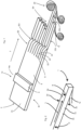
- FIG. 1 shows a schematic representation to illustrate the procedure according to the invention.
- a foam carrier 2 with a surface 2c is transported in a transport direction T in an area B1.
- This transport direction T also corresponds to the longitudinal direction of the sealing tape to be produced later.
- This surface is processed with a processing device 6 (shown only schematically).
- this is a heating device that heats the foam carrier 2 and, in particular, melts it in sections.
- This processing device 6 can be designed as a heated roller which contacts said surface of the foam carrier 2 . However, it could also be heating devices such as infrared elements, which are arranged slightly above the foam carrier and heat it.
- a self-skin 8 is formed on the surface 2c, d. H.
- the foam carrier now has different physical properties on this very surface 2c than on its other surfaces.
- the foam carrier also has other physical properties on this very surface 2c than in its interior.
- a coating (not shown) to the surface 2d (not shown) opposite the surface 2c.
- a coating could for example be glued to this opposite surface.
- Such a coating could be a sheet unwound from a roll (not shown) and applied to the opposite surface.
- this surface 2d it would also be possible for this surface 2d to also be processed and in particular heated in order to achieve a skin on this side as well.
- a multiplicity of cuts S are made in the foam carrier 2, which has already been provided with the coating 14. These cuts are parallel to one another and also extend in the transport direction T. These cuts produce a large number of strips 22, 24, 26 which are parallel to one another and which extend in the transport direction T.
- these individual strips are each rotated counterclockwise by 90°, so that the surfaces provided with the self-skin 8 each point to the right, viewed in the transport direction. If a coating or skin is applied to the opposite surface 2d, a corresponding coating or skin would also be present on the left-hand surface viewed in the direction of transport after rotation.
- an adhesive layer 12 is attached to the underside of the individual cut strips. It is possible that the strips are already compressed onto these adhesive layers.
- the individual sealing tapes are then rolled up (not shown) onto a sealing tape roll 20.
- Reference numerals 22b and 24b identify two surfaces on which the coating is arranged.
- FIG. 2 shows a schematic representation of a sealing tape 1 in an unrolled, ie freely fully expanded state.
- This sealing tape has a longitudinal direction L, as well as a width direction B perpendicular to this longitudinal direction L and a thickness direction D.
- Reference number 2c refers to a surface of the sealing tape which has the skin 8 .
- a coating or skin could also be arranged on the rear surface 2d.
- the skin 8 on the side surface 2c and the optionally present coating or skin on the side surface 2d preferably differ from one another in at least one physical property.
- Numeral 12 denotes an adhesive layer which is arranged on a downwardly facing surface 2b.
- the surface 2a is neither coated nor provided with an adhesive layer.
Description
Die vorliegende Erfindung bezieht sich auf ein Verfahren zum Herstellen eines Dichtbandes und auf ein Dichtband. Aus dem Stand der Technik sind unterschiedlichste Dichtbänder für unterschiedlichste Anwendungsbereiche bekannt. So sind auch Dichtbänder bekannt, welche auf einem Schaumstoffträger eine Beschichtung aufweisen, welche beispielsweise die Dampfdiffusion reduzieren soll. Aus dem Stand der Technik sind diverse Vorgehensweisen für die Herstellung derartiger Dichtbänder bekannt. So ist es beispielsweise bekannt, dass ein Schaumstoffträger aufgeschnitten wird und in einen Schnittbereich eine Folie eingebracht wird.
Diese Vorgehensweisen sind jedoch relativ aufwändig. Der vorliegenden Erfindung liegt daher die Aufgabe zugrunde, ein Verfahren zur Verfügung zu stellen, welches in einfacherer Weise eine Herstellung derartiger Dichtbänder ermöglicht. Diese Aufgabe wird erfindungsgemäß durch den Gegenstand des unabhängigen Patentanspruchs gelöst. Weiterhin liegt der vorliegenden Erfindung die Aufgabe zugrunde, ein Dichtband zur Verfügung zu stellen, welches einerseits eine einfache Anordnung an einem Bauteil bzw. einer Wandung ermöglicht und andererseits einen zufriedenstellenden Dichteffekt bewirkt.However, these procedures are relatively complex. The present invention is therefore based on the object of providing a method which makes it possible to produce such sealing tapes in a simpler manner. This object is achieved according to the invention by the subject matter of the independent patent claim. Furthermore, the present invention is based on the object of making available a sealing strip which on the one hand enables a simple arrangement on a component or a wall and on the other hand brings about a satisfactory sealing effect.
Bei einem erfindungsgemäßen Verfahren zum Herstellen eines Dichtbandes wird zunächst ein Schaumstoffträger zur Verfügung gestellt und dieser wenigstens zeitweise in einer vorgegebenen Transportrichtung transportiert. In einem weiteren Verfahrensschritt wird wenigstens eine erste Oberfläche des Schaumstoffträgers bearbeitet und/oder auf diese Oberfläche (insbesondere thermisch d. h. durch Erwärmung und/oder Erhitzung eingewirkt. In einem weiteren Verfahrensschritt wird der Schaumstoffträger in wenigstens zwei und bevorzugt eine Vielzahl von Streifen geschnitten. Weiterhin wird an einer weiteren Oberfläche der einzelnen Streifen eine Selbstklebung angebracht.In a method according to the invention for producing a sealing tape, a foam carrier is first made available and this is transported at least temporarily in a predetermined transport direction. In a further process step, at least a first surface of the foam carrier is processed and/or onto this surface (In particular thermally, ie by heating and/or heating. In a further process step, the foam backing is cut into at least two and preferably a large number of strips. Furthermore, a self-adhesive is applied to another surface of the individual strips.
Erfindungsgemäß beinhaltet die Bearbeitung der Oberfläche zumindest eine Erwärmung dieser Oberfläche.According to the invention, the processing of the surface includes at least one heating of this surface.
Bevorzugt handelt es sich um eine Oberfläche, welche sich zumindest auch in der Transportrichtung des Schaumstoffträgers erstreckt. Bevorzugt erstreckt sich diese Oberfläche auch senkrecht zu dieser Oberfläche. Bevorzugt ist diese Oberfläche horizontal ausgerichtet.It is preferably a surface which at least also extends in the transport direction of the foam carrier. This surface preferably also extends perpendicularly to this surface. This surface is preferably aligned horizontally.
Auf diese Weise wird erreicht, dass jeder der geschnittenen Streifen an einer Oberfläche eine veränderte physikalische Struktur und insbesondere eine Verhautung aufweist und an einer weiteren Oberfläche eine Selbstklebung aufweist. Vorteilhaft stehen dabei diese beiden Flächen senkrecht zueinander. Bei einem weiteren bevorzugten Verfahren weisen diese Streifen jeweils einen im Wesentlichen rechteckigen Querschnitt auf.In this way it is achieved that each of the cut strips has a modified physical structure and in particular a skin on one surface and self-adhesive on another surface. These two surfaces are advantageously perpendicular to one another. In a further preferred method, these strips each have a substantially rectangular cross-section.
Bei der bearbeiteten Oberfläche handelt es sich insbesondere um eine Oberfläche, die aufgrund der thermischen Bearbeitung und insbesondere der Erwärmung eine verringerte Durchlässigkeit für Dampf, Gas oder Flüssigkeiten aufweist.The processed surface is in particular a surface which, due to the thermal processing and in particular the heating, has reduced permeability to vapour, gas or liquids.
Im Gegensatz zum internen Stand der Technik der Anmelderin wird daher an der besagten Oberfläche keine (oder nicht nur eine) Beschichtung angebracht, sondern es wird direkt das Material des Schaumstoffträgers bearbeitet und insbesondere erwärmt bzw. erhitzt. Bevorzugt wird das Material des Schaumstoffs derart erhitzt, dass an der erwärmten Oberfläche physikalische Veränderungen des Schaumstoffs auftreten.In contrast to the applicant's internal state of the art, no (or not only one) coating is therefore applied to the said surface, but the material of the foam carrier is processed directly and in particular heated or heated. The material of the foam is preferably heated in such a way that physical changes in the foam occur on the heated surface.
Durch die oben erwähnte Erwärmung der Oberfläche und insbesondere eine Erhitzung des Schaumstoffträgers entsteht an dieser besagten Oberfläche eine sogenannte Selbstverhautung bzw. eine Hautschicht, die jedoch auf dem gleichen PU-Schaummaterial basiert, wie der Schaumstoffträger selbst.The above-mentioned heating of the surface and in particular heating of the foam carrier creates a so-called self-skin or skin layer on this surface, which is based on the same PU foam material as the foam carrier itself.
Bevorzugt werden bei diesem Prozess entstehende Dämpfe abgeführt. Insbesondere werden diese Dämpfe abgeführt und/oder gereinigt, insbesondere um Bedienungspersonal zu schützen.Vapors produced during this process are preferably removed. In particular, these vapors are discharged and/or cleaned, in particular to protect operators.
Im Gegensatz zum Stand der Technik wird also vorgeschlagen, dass kein zusätzliches Material oder eine zusätzliche Beschichtung aufgebracht wird, sondern diese Oberfläche behandelt wird, insbesondere wärmebehandelt wird und sich bevorzugt in wenigstens einer physikalischen Eigenschaft verändert.In contrast to the prior art, it is therefore proposed that no additional material or an additional coating is applied, but that this surface is treated, in particular heat-treated, and preferably changes in at least one physical property.
Dabei ist es möglich, dass insbesondere an einer Seitenfläche bzw. Oberfläche der insgesamt entstehenden Streifen eine Verhautung durch den genannten Kalandrierprozess entsteht und eine andere Seitenfläche eine Selbstklebung angeordnet ist bzw. wird.It is possible that, in particular on one side surface or surface of the strips produced as a whole, a skin is formed by the calendering process mentioned and that self-adhesive is or will be arranged on another side surface.
Bei einem bevorzugten Verfahren wird durch die Erwärmung ein vorgegebener Anteil der Dicke des Schaumstoffträgers abgeschmolzen. Bevorzugt erfolgt dabei diese Abschmelzung im Wesentlichen einheitlich, das heißt im Wesentlichen einheitlich über die besagte Oberfläche des Schaumstoffträgers hinweg. Durch diesen Abschmelzvorgang ergibt sich bevorzugt auch eine physikalische und/oder chemische Veränderung des Schaumstoffträgers.In a preferred method, the heating melts away a predetermined portion of the thickness of the foam backing. This melting preferably takes place essentially uniformly, that is to say essentially uniformly over said surface of the foam carrier. This melting process preferably also results in a physical and/or chemical change in the foam backing.
Bei einem weiteren bevorzugten Verfahren wird die genannte erste Oberfläche mit einer Temperatur bearbeitet und/oder auf eine Temperatur erhitzt, die größer ist als 100°C, bevorzugt größer als 150°C, bevorzugt größer als 200°C und besonders bevorzugt größer als 250°C. Bei einem weiteren bevorzugten Verfahren wird die genannte erste Oberfläche mit einer Temperatur bearbeitet und/oder auf eine Temperatur erhitzt, die kleiner ist als 1000°C, bevorzugt kleiner als 800°C, bevorzugt kleiner als 600°C und besonders bevorzugt kleiner als 400°C.In another preferred method, said first surface is treated at and/or heated to a temperature greater than 100°C, preferably greater than 150°C, preferably greater than 200°C and most preferably greater than 250°C C In a further preferred method, said first surface is treated at a temperature and/or heated to a temperature which is less than 1000°C, preferably less than 800°C, preferably less than 600°C and particularly preferably less than 400°C C
Bevorzugt erfolgt die Bearbeitung durch Kontakt des Schaumstoffträgers mit einer erhitzten Rolleneinrichtung. Es wäre jedoch auch möglich, diese Erhitzung auf andere Weise zu erreichen, etwa durch Infrarotheizelemente, denen gegenüber der Schaumstoffträger bewegt wird.The processing is preferably carried out by contacting the foam carrier with a heated roller device. However, it would also be possible to achieve this heating in a different way, for example by means of infrared heating elements, with respect to which the foam support is moved.
Es wäre jedoch auch möglich, dass gleichzeitig mit dem Erhitzen und insbesondere durch eine Rolleneinrichtung auch Druck auf den Schaumstoffträger ausgeübt wird. Weiterhin ist es möglich, dass es sich bei der Rolleneinrichtung um eine Transportwalze handelt, welche den Schaumstoffträger auch fördert.However, it would also be possible for pressure to also be exerted on the foam carrier simultaneously with the heating and in particular by means of a roller device. Furthermore it is possible that the roller device is a transport roller, which also promotes the foam carrier.
Dabei wird bevorzugt die Verhautung in einer einheitlichen Dicke oder in einer im Wesentlichen einheitlichen Dicke hergestellt.In this case, the skin is preferably produced with a uniform thickness or with a substantially uniform thickness.
Bei einem weiteren bevorzugten Verfahren wird eine Dicke des Schaumstoffträgers um wenigstens einen Zentimeter durch die Bearbeitung der Oberfläche reduziert. Bevorzugt wird die Dicke um wenigstens 0,5cm, bevorzugt um wenigstens 1,5 cm und bevorzugt um wenigstens 2,5 cm reduziert. Bevorzugt wird die Dicke des Schaumstoffträgers durch die Bearbeitung der Oberfläche um höchstens 10 cm, bevorzugt um höchstens 8 cm, bevorzugt um höchstens 6 cm, bevorzugt um höchstens 5 cm und bevorzugt um höchstens 4 cm reduziert.In a further preferred method, a thickness of the foam backing is reduced by at least one centimeter by processing the surface. Preferably the thickness is reduced by at least 0.5 cm, preferably by at least 1.5 cm and preferably by at least 2.5 cm. The thickness of the foam backing is preferably reduced by a maximum of 10 cm, preferably a maximum of 8 cm, preferably a maximum of 6 cm, preferably a maximum of 5 cm and preferably a maximum of 4 cm by processing the surface.
Bei einer bevorzugten Ausführungsform weist die so entstehende Oberfläche, welche bearbeitet wurde, eine Dicke auf, die kleiner ist als 4 mm, bevorzugt kleiner als 3 mm, bevorzugt kleiner als 2 mm und besonders bevorzugt kleiner als 1 mm.In a preferred embodiment, the resulting surface which has been processed has a thickness of less than 4 mm, preferably less than 3 mm, preferably less than 2 mm and particularly preferably less than 1 mm.
Bei einem weiteren bevorzugten Verfahren handelt es sich bei dem Schaumstoffträger um einen imprägnierten Schaumstoffträger. Dabei ist es möglich und bevorzugt, dass dieser imprägnierte Schaumstoffträger getrocknet wird, bevor er wie oben beschrieben bearbeitet wird.In another preferred method, the foam backing is an impregnated foam backing. It is possible and preferred here for this impregnated foam backing to be dried before it is processed as described above.
Bevorzugt ist es dabei möglich, dass die Bearbeitung der Oberfläche an einem imprägnierten und getrockneten Schaumstoffträger oder an einem unimprägnierten Schaumstoffträger vorgenommen wird.It is preferably possible here for the surface to be processed on an impregnated and dried foam backing or on an unimpregnated foam backing.
Daneben wäre es auch denkbar, dass Abschmelzen mittels Strahlung und insbesondere mittels Laserstrahlung durchzuführen. Dabei wäre sowohl ein punktuelles als auch ein flächiges Abschmelzen möglich.In addition, it would also be conceivable for the melting to be carried out by means of radiation and in particular by means of laser radiation. In this case, both a selective and a surface melting would be possible.
Bei einem bevorzugten Verfahren wird in einem weiteren Verfahrensschritt wenigstens einer und bevorzugt eine Vielzahl der geschnittenen Streifen um einen vorgegebenen Winkel gedreht. Dabei wäre es möglich, dass nur einer der geschnitten Streifen gedreht wird, es könnten mehrere der Streifen oder auch alle der Streifen um einen vorgegebenen Winkel gedreht werden.In a preferred method, in a further method step, at least one and preferably a large number of the cut strips are rotated through a predetermined angle. It would be possible that only one of the cut strips is rotated, it could several of the strips or even all of the strips can be rotated by a predetermined angle.
Bevorzugt erfolgt diese Drehung bezüglich einer Längsrichtung der einzelnen Streifen und/oder einer Richtung, welche zu der Transportrichtung parallel ist. Bevorzugt werden sämtliche Streifen einheitlich gedreht und/oder jeweils um den gleichen Winkel gedreht.This rotation preferably takes place with respect to a longitudinal direction of the individual strips and/or a direction which is parallel to the transport direction. All of the strips are preferably rotated uniformly and/or each rotated by the same angle.
Bevorzugt wird die Bearbeitung lückenlos und/oder durchgehend an dem Schaumstoffträger bzw. der genannten Oberfläche durchgeführt bzw. angebracht. Vorteilhaft erstrecken sich die besagten Schnitte ebenfalls in einer Transportrichtung des Schaumstoffträgers. Dabei ist es jedoch möglich, dass der Schaumstoffträger beim Einbringen der Schnitte ruht, beispielsweise auf einer Ablage liegt.The processing is preferably carried out or applied without gaps and/or continuously on the foam carrier or the surface mentioned. Said cuts also advantageously extend in a transport direction of the foam carrier. However, it is possible that the foam carrier is at rest when the cuts are made, for example lying on a shelf.
Bei einem weiteren bevorzugten Verfahren erstreckt sich der Schaumstoffträger in der Transportrichtung und in einer hierzu senkrechten Breitenrichtung. Dabei kann sich der Schaumstoffträger in der besagten Breitenrichtung beispielsweise um einen Meter erstrecken.In a further preferred method, the foam carrier extends in the transport direction and in a width direction perpendicular thereto. In this case, the foam carrier can extend, for example, by one meter in said width direction.
Bei einem bevorzugten Verfahren wird zunächst eine Bearbeitung an der ersten Oberfläche des Schaumstoffträgers vorgenommen, anschließend erfolgt das Schneiden des Schaumstoffes und anschließend wird die Selbstklebung angebracht.A preferred method involves first machining the first surface of the foam backing, then cutting the foam, and then applying the self-adhesive.
Es wäre jedoch auch denkbar, zunächst eine Selbstklebung anzubringen, anschließend den Schaumstoff mit der daran angeordneten Selbstklebung in Streifen zu schneiden und schließlich noch die Bearbeitung durchzuführen.However, it would also be conceivable to first apply a self-adhesive, then to cut the foam with the self-adhesive arranged thereon into strips and finally to carry out the processing.
Daneben wäre es auch denkbar, zunächst den Schaumstoffträger in Streifen zu schneiden und anschließend an diesem, bevorzugt zeitgleich, sowohl die Bearbeitung durchzuführen als auch die Selbstklebung anzubringen.In addition, it would also be conceivable to first cut the foam carrier into strips and then, preferably at the same time, to carry out both the processing and the self-adhesive application.
Bevorzugt behält die bearbeitete Oberfläche auch nach der Bearbeitung eine gewisse Flexibilität bei.The machined surface preferably retains a certain flexibility even after machining.
Bevorzugt könnte auch zusätzlich noch zu der Bearbeitung eine Beschichtung an der besagten Oberfläche und/oder an einer dieser gegenüberliegenden Oberfläche angeordnet werden.In addition to the processing, a coating could preferably also be arranged on said surface and/or on a surface opposite thereto.
Bei einem bevorzugten Verfahren handelt es sich bei der zusätzlichen Beschichtung um eine flexible Beschichtung. Vorteilhaft handelt es sich hierbei um eine dünne Beschichtung. Diese weist besonders bevorzugt eine Dicke auf, die zwischen 10µm und 1mm, bevorzugt zwischen 50µm und 200µm liegt. Weiterhin ist besonders bevorzugt die Beschichtung aus einer Gruppe von Beschichtungen ausgewählt, welche Kunststoffmaterialien enthält.In a preferred method, the additional coating is a flexible coating. Advantageously, this is a thin coating. This particularly preferably has a thickness of between 10 μm and 1 mm, preferably between 50 μm and 200 μm. Furthermore, the coating is particularly preferably selected from a group of coatings which contains plastic materials.
Bei einer bevorzugten Ausführungsform handelt es sich bei der Beschichtung um eine Folienbeschichtung bzw. Folienkaschierung. Diese Beschichtung besteht bevorzugt aus einem Kunststoff, der aus einer Gruppe von Kunststoffen ausgewählt ist, welche PU, PP, PE, PVC, PET, TPU und dergleichen enthält. Daneben können auch metallisierte Kunststoffe verwendet werden.In a preferred embodiment, the coating is a film coating or film lamination. This coating preferably consists of a plastic which is selected from a group of plastics which contains PU, PP, PE, PVC, PET, TPU and the like. In addition, metallized plastics can also be used.
Daneben wäre es auch möglich, als Beschichtung eine Metallfolie zu verwenden. Darüber hinaus könnten auch Vliesstoffe verwendet werden, die dabei mit oder ohne eine/r Imprägnierung verwendet werden könnten. Schließlich könnten auch elastische Membranen, wie etwa EPDM-Folien verwendet werden. Daneben wäre es auch denkbar, dass es sich bei der Beschichtung um eine Kaschierung mit einer weiteren Schicht Schaumstoff handelt. Dieser weitere Schaumstoff kann dabei in imprägnierter oder nicht imprägnierter Ausführung zur Verfügung stehen. Dabei kann für diesen weiteren Schaumstoff ebenfalls ein Schaumstoff aus einer Gruppe von Schaumstoffen ausgewählt werden, welche PU, PP, PE, PVC, TPU, EPDM und dergleichen enthält.In addition, it would also be possible to use a metal foil as the coating. In addition, nonwovens could also be used, which could be used with or without impregnation. Finally, elastic membranes such as EPDM foils could also be used. In addition, it would also be conceivable for the coating to be a lamination with a further layer of foam. This further foam can be available in an impregnated or non-impregnated version. A foam can also be selected for this additional foam from a group of foams which contains PU, PP, PE, PVC, TPU, EPDM and the like.
Der Vorteil, eine zusätzliche elastische und/oder flexible Folie und/oder Kaschierung bzw. Beschichtung zu verwenden liegt darin, dass das Anlegen von Längskanten dieser Schicht an Fugenflanken, der sogenannte Flankenschluss, leichter ermöglicht wird. Je nach vorgesehener Anwendung des Dichtbandes sollte die Kaschierung bzw. die Beschichtung diese Anforderungen erfüllen. Bei zusätzlichen Anwendungen wäre es auch möglich oder zusätzlich möglich, dass diese Beschichtungen UV-beständig, wasserfest, schlagregendicht, überstreichbar und/oder überputzbar sind.The advantage of using an additional elastic and/or flexible foil and/or lamination or coating is that it is easier to apply longitudinal edges of this layer to joint flanks, the so-called flank closure. Depending on the intended application of the sealing tape, the lamination or the coating should meet these requirements. In the case of additional applications, it would also be possible or additionally possible for these coatings to be UV-resistant, waterproof, impervious to driving rain, paintable and/or plasterable.
In einem weiteren Verfahren ist es auch denkbar, dass die Schaumstoffbahn nicht nur einseitig, sondern beidseitig bearbeitet wird, und insbesondere an zwei aneinander gegenüberliegenden Seiten. Dabei ist es dann denkbar, dass diese Ober- und Unterseite des Vorprodukts der Schaumstoffbahn eine Innen- und Außenseite des Endprodukts Dichtband ergeben. Der Vorteil einer derartigen beidseitigen Bearbeitung bzw. Erwärmung, könnten Beschichtungen mit unterschiedlichen Eigenschaften speziell auf die Anforderungen der Ausrichtungen Endprodukt sein.In a further method, it is also conceivable that the foam web is processed not just on one side, but on both sides, and in particular on two opposite sides. It is then conceivable that this upper and lower side of the preliminary product of the foam web result in an inner and outer side of the sealing tape end product. The advantage of such a double-sided processing or heating could be coatings with different properties specifically tailored to the requirements of the end product alignment.
Es wäre auch denkbar, dass an einer Seite eine Bearbeitung vorgenommen wird und an der gegenüberliegenden Seite eine Beschichtung, insbesondere eine Beschichtung der oben genannten Art aufgebracht wird.It would also be conceivable for machining to be carried out on one side and a coating, in particular a coating of the type mentioned above, to be applied to the opposite side.
Denkbar wäre hier beispielsweise eine UV-stabile Beschichtung und eine dampfoffene Beschichtung auf einer Außenseite und dagegen eine (dampfdichtende bzw. dampfbremsende und luftdichte) Bearbeitung auf der Innenseite.It would be conceivable here, for example, to have a UV-stable coating and a vapor-permeable coating on an outside and, on the other hand, a (vapour-tight or vapor-retarding and airtight) treatment on the inside.
Bevorzugt wird der Schaumstoffträger kontinuierlich transportiert. Es wäre jedoch auch ein getakteter Transport denkbar. Dabei ist es möglich, dass der Schaumstoffträger selbst während des Einbringens der Schnitte ruht und stattdessen sich Schneidemesser bewegen und insbesondere sich in einer vorgegebenen Längsrichtung des Schaumstoffträgers bewegen und insbesondere in der Richtung, in der der Schaumstoffträger ansonsten, das heißt wenn nicht die Schnitte eingebracht werden, transportiert wird.The foam carrier is preferably transported continuously. However, clocked transport would also be conceivable. It is possible that the foam backing itself is stationary while the cuts are being made and instead the cutting blades move and in particular move in a predetermined longitudinal direction of the foam backing and in particular in the direction in which the foam backing would otherwise, i.e. if the cuts are not made , is transported.
Bei den Messern kann es sich beispielsweise um sich drehende Messer handeln bzw. um Messerscheiben.The knives can, for example, be rotating knives or knife discs.
Bei einem weiteren bevorzugten Verfahren ist der Schaumstoffträger ein imprägnierter Schaumstoffträger, besonders bevorzugt ein zur verzögerten Rückstellung imprägnierter Schaumstoffträger. Vorteilhaft ist der Schaumstoffträger auch ein getrockneter Schaumstoffträger und besonders bevorzugt ein Schaumstoffträger, der vor der Bearbeitung imprägniert und getrocknet wurde. Die Bearbeitung kann sowohl vor als auch nach dem Imprägnieren vorgenommen werden.In another preferred method, the foam backing is an impregnated foam backing, more preferably a foam backing impregnated for delayed recovery. The foam backing is also advantageously a dried foam backing and particularly preferably a foam backing which has been impregnated and dried prior to processing. Processing can be carried out both before and after impregnation.
Bei einem bevorzugten Verfahren werden als Imprägnate wässrige Dispersionen verwendet. Bevorzugt werden wässrige Dispersionen mit Acrylat-Bindern verwendet. Daneben könnten jedoch auch andere Imprägnierungen verwendet werden, insbesondere Kleb- oder Dichtstoffe in verschieden flüssigen Medien. Bei diesen Kleb- oder Dichtstoffen kann es sich beispielsweise um Acrylate, Bitumen, Polyurethane, Harze und dergleichen handeln.In a preferred method, aqueous dispersions are used as impregnates. Aqueous dispersions with acrylate binders are preferably used. In addition, however, other impregnations could also be used, in particular adhesives or sealants in different liquid media. These adhesives or sealants can be, for example, acrylates, bitumen, polyurethanes, resins and the like.
Als flüssige Medien kommen beispielsweise Wasser mit oder ohne Zusatzstoffe oder auch organische Lösungsmittel in Betracht.Water with or without additives or else organic solvents can be considered as liquid media, for example.
Bei dem Schaumstoffträger kann es sich beispielweise um einen Polyurethan-Schaumstoff handeln. Dieser Schaustoff weist dabei bevorzugt einen Rohdichte auf, die zwischen 5 und 100 kg/m3, bevorzugt zwischen 10 und 80 kg/m3, bevorzugt zwischen 10 und 60 kg/m3, bevorzugt zwischen 15 und 50 kg/m3 und besonders bevorzugt zwischen 20 und 40 kg/m3 liegt.The foam carrier can be, for example, a polyurethane foam. This foam preferably has a bulk density of between 5 and 100 kg/m 3 , preferably between 10 and 80 kg/m 3 , preferably between 10 and 60 kg/m 3 , preferably between 15 and 50 kg/m 3 and particularly preferably between 20 and 40 kg/m 3 .
Bevorzugt weist der Schaumstoff (in dem unbearbeiteten Zustand) eine Stauchhärte auf, die zwischen 1 kPa und 8 kPa, bevorzugt zwischen 2 kPa und 6 kPa, bevorzugt zwischen 3 kPa und 4 kPa liegt.The foam (in the unprocessed state) preferably has a compressive strength of between 1 kPa and 8 kPa, preferably between 2 kPa and 6 kPa, preferably between 3 kPa and 4 kPa.
Bei einer bevorzugten Ausführungsform liegt eine Luftdurchlässigkeit des (unbearbeiteten) Schaumstoffs zwischen 100 und 10 000 l/m3/s, bevorzugt zwischen 200 und 5 000 l/(m3 *s), bevorzugt zwischen 200 und 2 000 l/(m3 *s), besonders bevorzugt zwischen 300 und 900 l/(m3 *s). Diese Werte beziehen sich dabei auf eine Messung nach DIN EN ISO 9237, mit einer Prüfkörperdicke von 10 mm, einer Prüffläche von 10 cm2, einem Prüfunterdruck von 0,5 mbar. Bei dem Messgerät handelt es sich um ein Frank-Gerät Typ 21443. An einem Muster von 10 mm dickem imprägnierten Schaum wurden bei vorstehenden Randbedingungen ca. 700 l/m2 x sec gemessen.In a preferred embodiment, the air permeability of the (unprocessed) foam is between 100 and 10,000 l/m 3 /s, preferably between 200 and 5,000 l/(m 3 *s), preferably between 200 and 2,000 l/(m 3 ) . *s), particularly preferably between 300 and 900 l/(m 3 *s). These values relate to a measurement according to DIN EN ISO 9237, with a test specimen thickness of 10 mm, a test area of 10 cm 2 , and a negative test pressure of 0.5 mbar. The measuring device is a Frank device type 21443. Approx. 700 l/
Der bearbeitete Schaumstoff weist (unter Verwendung der obigen Messbedingungen) eine Luftdurchlässigkeit auf, die größer ist als 10 l/m3/s, bevorzugt größer als 20 l/m3/s. Bevorzugt ist die Luftdurchlässigkeit geringer als 200 l/m3/s, bevorzugt geringer als 100 l/m3/s.The processed foam has (using the above measurement conditions) an air permeability greater than 10 l/m 3 /s, preferably greater than 20 l/m 3 /s. The air permeability is preferably less than 200 l/m 3 /s, preferably less than 100 l/m 3 /s.
Bei einem weiteren bevorzugten Verfahren werden die einzelnen Streifen um jeweils 90 ° bezüglich der Transportrichtung gedreht. Weiterhin erfolgt bevorzugt ein Ablängen der Streifen. Das Ablängen erfolgt in der Regel und bevorzugt als Bahn, aus dieser werden dann die - schon abgelängten - Streifen geschnitten.In a further preferred method, the individual strips are each rotated by 90° with respect to the transport direction. Furthermore, the strips are preferably cut to length. The cutting to length is usually and preferably done as a web, from which the strips - already cut to length - are then cut.
Bei einem bevorzugten Verfahren wird die Bearbeitung auf einer nach oben oder unten weisenden Oberfläche des Schaumstoffträgers vorgenommen. Bevorzugt liegt damit nach dem Drehen der einzelnen Streifen um 90 ° diese bearbeitete Oberfläche in einer vertikalen Ausrichtung. So kann die Drehung der Schaumstoffstreifen sowohl um 90 ° in als auch um 90 ° entgegen dem Uhrzeigersinn erfolgen.In a preferred method, the machining is done on an upward or downward facing surface of the foam backing. After the individual strips have been rotated by 90°, this machined surface is preferably in a vertical alignment. The foam strips can thus be rotated 90° clockwise as well as 90° counterclockwise.
Es ist auch denkbar, dass nach dem Schneiden die Streifen nicht gedreht werden. Hier kann eine Variante des Verfahrens angewendet werden, bei dem die Selbstklebung seitlich zu den Steifen geführt wird und bevorzugt Einzelrollen liegend komprimiert und aufgerollt werden.It is also conceivable that the strips are not rotated after cutting. A variant of the method can be used here, in which the self-adhesive is guided laterally to the stiffeners and preferably individual rolls are compressed and rolled up lying flat.
Bei diesem Verfahren wäre es denkbar, dass zunächst die einzelnen Streifen geschnitten werden und anschließend bevorzugt in einer zu der Transportrichtung senkrecht stehenden Richtung gegenüber einander verschoben werden, so dass insbesondere auch die Seitenflächen dieser Streifen für die Anbringung einer Selbstklebung zugänglich werden. Dabei wäre es sowohl denkbar, dass die Streifen in einer Höhenrichtung gegenüber einander versetzt werden, etwa beispielsweise abwechselnd nach oben und nach unten versetzt werden.In this method it would be conceivable that the individual strips are first cut and then preferably shifted in relation to one another in a direction perpendicular to the transport direction, so that in particular the side surfaces of these strips are also accessible for the attachment of a self-adhesive. It would be conceivable here for the strips to be offset relative to one another in a vertical direction, for example alternately offset upwards and downwards.
Auch wäre es denkbar, dass die einzelnen Streifen in einer (ebenfalls zu der Transportdichtung senkrecht stehenden) Breitenrichtung zueinander versetzt werden und auch hierdurch die einzelnen Seitenflächen für die Anbringung der Selbstklebung zugänglich werden.It would also be conceivable for the individual strips to be offset relative to one another in a width direction (likewise perpendicular to the transport seal) and for this also to make the individual side faces accessible for the application of the self-adhesive.
Bei einem bevorzugten Verfahren werden daher wenigstens einige der geschnittenen Streifen derart bezüglich einander verschoben bzw. versetzt, sodass deren Seitenflächen, bei denen es sich insbesondere um diejenigen Flächen handelt, entlang derer die Schnitte erfolgt sind, für die Anbringung der Selbstklebung zugänglich werden.In a preferred method, at least some of the cut strips are therefore shifted relative to one another in such a way that their side surfaces, which are in particular those surfaces along which the cuts were made, become accessible for the application of the self-adhesive.
Bevorzugt könnten bei diesem Verfahren zwischen den einzelnen geschnittenen Streifen bewusst Zwischenräume erzeugt werden, in denen die Selbstklebungen eingefügt werden können. Zum Einfügen dieser Selbstklebungen könnten etwa Wellenstummel verwendet werden, welche in diese Zwischenräume ragen.With this method, spaces between the individual cut strips could preferably be deliberately created, in which the self-adhesives can be inserted. To insert these self-adhesives, stub shafts could be used, for example, which protrude into these intermediate spaces.
Durch die Drehung um 90 ° können mehrere Einzelrollen auf einer Welle mit einem Antrieb gewickelt werden. Wenn auf die Drehung verzichtet wird, kann bevorzugt für jede Einzelrolle ein Wellenstummel verwendet werden, wobei bevorzugt jeweils ein separater Antrieb für den Wellenstummel vorgesehen ist.Due to the 90° rotation, several individual rolls can be wound on one shaft with one drive. If the rotation is dispensed with, a stub shaft can preferably be used for each individual roller, with a separate drive for the stub shaft preferably being provided in each case.
Bei einem weiteren bevorzugten Verfahren werden die geschnittenen Streifen wenigstens teilweise aufgerollt, wobei bevorzugt während dieses Aufrollens die Streifen in wenigstens einer Richtung komprimiert werden.In a further preferred method, the cut strips are at least partially rolled up, the strips preferably being compressed in at least one direction during this rolling up.
Vorteilhaft wird dabei diejenige Oberfläche, auf der die Beschichtung aufgebracht ist, komprimiert.Advantageously, that surface on which the coating is applied is compressed.
Bevorzugt erfolgt eine Komprimierung auf weniger als 25 % der Ausgangshöhe des frei voll expandierten Schaumstoffstreifens, bevorzugt auf weniger als 20 % der Ausgangshöhe, bevorzugt auf weniger als 18 % und besonders bevorzugt auf weniger als 15 % der Ausgangshöhe. Letzteres bedeutet, dass der Schaumstoffstreifen um 85 % komprimiert wird.Compression preferably takes place to less than 25% of the initial height of the freely fully expanded foam strip, preferably to less than 20% of the initial height, preferably to less than 18% and particularly preferably to less than 15% of the initial height. The latter means that the foam strip is compressed by 85%.
Bei einem weiteren bevorzugten Verfahren werden die einzelnen Streifen bezüglich einer horizontalen Rollenachse aufgerollt.In a further preferred method, the individual strips are rolled up with respect to a horizontal roll axis.
Bei einem weiteren vorteilhaften Verfahren werden die Streifen zum Aufbringen der Selbstklebung auf ein Selbstklebeband geführt und insbesondere komprimiert. Damit erfolgt bevorzugt sowohl das Anbringen der Selbstklebung und auch das Komprimieren der Schaumstoffstreifen in einem gemeinsamen Schritt.In a further advantageous method, the strips for applying the self-adhesive are guided onto a self-adhesive tape and, in particular, compressed. In this way, both the application of the self-adhesive and the compression of the foam strips are preferably carried out in a common step.
Bei einem bevorzugten Verfahren verlaufen die expandierten Streifen zwischen zwei Komprimierwalzen. Zwischen diesen Komprimierwalzen werden die Streifen auf einen vorgesehenen Komprimiergrad (beispielsweise die oben genannten Werte oder beispielsweise 9 - 18%). Von einer Vorratsrolle wird eine Selbstklebung wie etwa ein Selbstklebestreifen zugeführt und an den komprimierten Schaum verhaftet und gepresst. Diese Kombination wird bevorzugt anschließend auf einen Kern aufgewickelt und mit einer oder mehreren Wicklungen Klebeband in der komprimierten Form gesichert.In a preferred method, the expanded strips pass between two compression rollers. Between these compression rollers, the strips are compressed to an intended degree of compression (e.g. the values mentioned above or e.g. 9-18%). A self-adhesive, such as a self-adhesive strip, is fed from a supply roll and adhered and pressed to the compressed foam. This combination is preferably then wound onto a core and secured in compressed form with one or more wraps of adhesive tape.
Grundsätzlich wäre es möglich, dass das Schneiden der Schaumstoffbahn in einem voll expandierten Zustand erfolgt oder auch in einem teilweise komprimierten Zustand. Bei einem bevorzugten Verfahren ist es denkbar, dass die bearbeitete Bahn, das heißt die bereits mit der bearbeiteten Oberfläche versehene Schaumstoffbahn in einer vollen Länge (beispielsweise 10 m) auf einen Tisch ausgelegt wird.In principle, it would be possible for the foam web to be cut in a fully expanded state or also in a partially compressed state. In a preferred method, it is conceivable that the processed web, ie the foam web already provided with the processed surface, is laid out over a full length (for example 10 m) on a table.
Von dieser Bahn werden anschließend einzelne Streifen geschnitten. Dieser Streifen kann dabei dem Prinzip einer Brotschneidemaschine folgen. Bevorzugt bewegt sich das Schneidewerkzeug, bei dem es sich beispielsweise um ein Rundmesser, eine Säge oder oszillierende Schneide handeln kann, um das Werkstück, das heißt der Schaumstoff bleibt liegen. Zum Fixieren der Schaumstoffbahn kann dabei mittels einer Druckvorrichtung, wie etwa einem Druckbalken oder Druckrollen, eine leichte Komprimierung erfolgen.Individual strips are then cut from this web. This strip can follow the principle of a bread slicer. The cutting tool, which can be, for example, a circular knife, a saw or an oscillating cutting edge, preferably moves around the workpiece, ie the foam material remains in place. To fix the foam web, slight compression can be carried out using a pressure device, such as a pressure bar or pressure rollers.
Bevorzugt ist die durch die Bearbeitung entstandene Oberfläche luftdicht. Dabei wäre es auch denkbar, dass diese luftdichte Oberfläche es auch ermöglicht, die Schaumstoffbahn mittels eines Vakuums zu fixieren.The surface created by the processing is preferably airtight. It would also be conceivable that this airtight surface also makes it possible to fix the foam sheet by means of a vacuum.
Auch wäre es denkbar, dass mehrere Streifen gleichzeitig mittels mehrerer Schneidwerkzeuge geschnitten werden.It would also be conceivable for several strips to be cut simultaneously using several cutting tools.
Bei einer weiteren bevorzugten Vorgehensweise wird die bereits bearbeitete Bahn ohne eine Selbstklebung komprimiert und aufgedockt. Von diesem Dock können wiederum Rollen, in einer gewünschten Breite abgestochen werden. Diese Rollen werden von der Weiterverarbeitung bevorzugt geöffnet und die Bänder können expandieren. Anschließend wird wie oben genauer beschrieben, die Selbstklebung aufgebracht.In a further preferred procedure, the web that has already been processed is compressed and docked without self-adhesive. In turn, rolls can be cut off in a desired width from this dock. These rolls are preferentially opened by further processing and the belts can expand. The self-adhesive is then applied as described in more detail above.
Bei dieser Vorgehensweise ergibt sich eine erhebliche Erleichterung bei der Zwischenlagerung und dem Transport der Vorprodukte.This procedure results in a considerable simplification of the intermediate storage and transport of the preliminary products.
Bei einem bevorzugtem Verfahren werden die Streifen derart geschnitten, dass die Streifen in einem im Wesentlichen vollständig expandierten Zustand einen mindestens quadratischen Querschnitt haben, das heißt eine Breite des Streifens größer als dessen Höhe ist. Dabei gibt die Breite die auf der Selbstklebung befindliche oder die ihr gegenüberliegende Seite an.In a preferred method, the strips are cut in such a way that the strips have an at least square cross-section in a substantially fully expanded state, i.e. a width of the strip is greater than its height. The width indicates the side on the self-adhesive or the side opposite it.
Bei einem weiteren bevorzugten Verfahren wäre es auch denkbar, dass die Schaumstoffbahn zunächst geschnitten wird und anschließend die Bearbeitung an den einzelnen Streifen vorgenommen wird. Bei dieser Vorgehensweise könnte auf und/oder an den Streifen eine Bearbeitung vor dem Komprimieren auf die Selbstklebefolie vorgenommen werden. Dabei wäre es auch denkbar, dass die Beschichtung seitlich aber auch oben, unten oder unten und oben aufgebracht wird.In a further preferred method, it would also be conceivable that the foam web is first cut and then the processing is carried out on the individual strips. With this procedure, processing could be carried out on and/or on the strips before they are compressed onto the self-adhesive film. It would also be conceivable that the coating is applied laterally but also above, below or below and above.
Zum Schneiden sind mehrere Vorgehensweisen denkbar. Dabei ist es möglich und bevorzugt, dass ein Schneiden nach dem Verhauten erfolgt. Dabei kann das Schneiden bei einem bevorzugten Verfahren mittels rotierender Schneidmesser erfolgen.Several approaches are conceivable for cutting. In this case, it is possible and preferred for cutting to take place after skinning. In a preferred method, the cutting can take place by means of rotating cutting blades.
Bei einem weiteren bevorzugten Verfahren wird das Schaumstoffmaterial zunächst verhautet bzw. wie oben erwähnt bearbeitet und anschließend imprägniert. In diesem Falle würde bewusst ein etwas aufwändigerer Trocknungsprozess in Kauf genommen werden, weil als Vorteil die Hautschicht stabiler wäre. Es wäre jedoch auch möglich, dass zunächst die Imprägnierung erfolgt und dann die Verhauten (d. h. das Schmelzen an einer Oberfläche).In a further preferred method, the foam material is first skinned or processed as mentioned above and then impregnated. In this case, a somewhat more complex drying process would be deliberately accepted because the skin layer would be more stable as an advantage. However, it would also be possible for the impregnation to take place first and then the skinning (i.e. melting at a surface).
Bevorzugt handelt es sich bei dem Selbstklebeband, wie oben erwähnt, um ein doppelseitiges Klebeband. Dabei kann dieses doppelseitige Klebeband auf der dem Schaumstoff abgewandten Seite zunächst noch mit einem Liner ausgestattet sein. In diesem Falle ist es möglich, dass ein Aufrollen der Kombination aus dem Schaumstoffträger, der Selbstklebung und dem Liner erfolgt.As mentioned above, the self-adhesive tape is preferably a double-sided adhesive tape. This double-sided adhesive tape can initially also be equipped with a liner on the side facing away from the foam. In this case it is possible that the combination of the foam backing, the self-adhesive and the liner will roll up.
In einem auf der Rolle aufgewickelten Zustand weist damit das Band eine außenliegende Bearbeitung auf.In a state wound up on the roll, the tape thus has an external treatment.
Bevorzugt handelt es sich bei dieser Beschichtung um eine Folienkaschierung oder um einen Dichtstoff.This coating is preferably a film lamination or a sealant.
Bei einem weiteren vorteilhaften Verfahren wird an einer zweiten Oberfläche des Schaumstoffträgers eine Beschichtung angebracht, Auf diese Weise wird eine Möglichkeit geschaffen eine gezielte Steuerung von Eigenschaften zu erreichen wie etwa innen diffusionshemmend und luftdicht, außen hingegen diffusionsoffen und schlagregendicht.In a further advantageous method, a coating is applied to a second surface of the foam carrier. In this way, it is possible to achieve a targeted control of properties such as diffusion-inhibiting and airtight on the inside, but diffusion-open and driving rain-proof on the outside.
Die vorliegende Erfindung ist weiterhin auf ein als Dichtbandrolle konfektioniertes Dichtband gerichtet, welches sich in einer ersten Längsrichtung und in einer zu dieser ersten Längsrichtung senkrechten Breitenrichtung erstreckt, wobei dieses Dichtband eine erste Oberfläche aufweist, welches sich in dieser Längsrichtung sowie der Breitenrichtung erstreckt und eine zweite Oberfläche aufweist, welche der ersten Oberfläche gegenüber liegt, wobei an einer dieser beiden Oberflächen eine Klebeschicht angeordnet ist.The present invention is also directed to a sealing tape made up as a roll of sealing tape, which extends in a first longitudinal direction and in a width direction perpendicular to this first longitudinal direction, this sealing tape having a first surface which extends in this longitudinal direction and the width direction and a second Has surface, which is opposite to the first surface, wherein an adhesive layer is arranged on one of these two surfaces.
Daneben weist das Dichtband eine dritte Oberfläche auf, welche sich in der Längsrichtung sowie in einer Dickenrichtung des Bandes erstreckt sowie eine vierte Oberfläche, welche der dritten Oberfläche gegenüber liegt und welche sich ebenfalls in der Längsrichtung und der Dickenrichtung erstreckt, wobei die dritte Oberfläche und/oder die vierte Oberfläche eine durch einen Erwärmungsprozess bearbeitete Oberfläche ist.In addition, the sealing tape has a third surface, which extends in the longitudinal direction and in a thickness direction of the tape, and a fourth surface, which is opposite the third surface and which also extends in the longitudinal direction and the thickness direction, the third surface and/or or the fourth surface is a surface worked by a heating process.
Weiterhin ist bevorzugt das Dichtband nach einem Verfahren der oben beschriebenen Art gefertigt.Furthermore, the sealing strip is preferably manufactured using a method of the type described above.
Bei einer weiteren vorteilhaften Ausführungsform ist das Dichtband in einem in der Dickenrichtung komprimierten Zustand aufgerollt. Daher liegen bevorzugt die dritte und vierte Oberfläche in dem aufgerollten Zustand jeweils nach außen bzw. sind Seiten oder Stirnflächen der Dichtbandrolle.In a further advantageous embodiment, the sealing tape is rolled up in a state compressed in the thickness direction. Therefore, preferably the third and fourth surfaces each face outwards or are sides or faces of the roll of sealing tape in the rolled-up state.
Bei einer weiteren vorteilhaften Ausführungsform ist an der bearbeiteten Oberfläche kein zusätzliches Material wie insbesondere eine Beschichtung angeordnet. Bevorzugt ist die bearbeitete Oberfläche aus dem gleichen Material hergestellt wie die übrigen Bereiche des Schaumstoffträgers.In a further advantageous embodiment, no additional material, such as in particular a coating, is arranged on the machined surface. The machined surface is preferably made of the same material as the remaining areas of the foam backing.
Bevorzugt besteht also der Schaumstoffträger von der dritten Oberfläche in Richtung der vierten Oberfläche aus dem gleichen Material. Dabei ist es denkbar, dass das Material durch den Bearbeitungsvorgang und insbesondere durch den Erhitzungsvorgang verändert wird.The foam backing is therefore preferably made of the same material from the third surface in the direction of the fourth surface. It is conceivable that the material is changed by the machining process and in particular by the heating process.
Bevorzugt sind also auch an der bearbeiteten Oberfläche keine weiteren Materialien angeordnet und insbesondere keine Materialien, die sich in einem Grundzustand, das heißt in einem nicht bearbeiteten Zustand von dem Material des Schaumstoffträgers unterscheiden.It is therefore preferred that no further materials are arranged on the processed surface either, and in particular no materials that differ from the material of the foam carrier in a basic state, ie in a non-processed state.
Bei einer weiteren vorteilhaften Ausführungsform unterscheidet sich die bearbeitete Oberfläche in wenigstens einer physikalischen Eigenschaft von anderen Oberflächen und insbesondere von dem Schaumstoffträger selbst.In a further advantageous embodiment, the processed surface differs from other surfaces and in particular from the foam carrier itself in at least one physical property.
Die Erhitzung und ein gewisser Druck (dessen Einstellung z. B. über Walzenspalt erfolgen kann) bewirken einen Schmelzprozess am unimprägnierten und imprägnierten Schaumstoff. Beispielsweise werden ca. 3 mm abgeschmolzen, die eine Haut von ca. 0,5 mm ergeben. Daran schließt sich nach unten eine Übergangszone von max. 5 mm an, die sich durch deformierte Zellen auszeichnet. Direkt an der Haut stärker deformiert als zu weiter ab von der Haut hin.The heating and a certain pressure (which can be adjusted, for example, via a roller gap) cause a melting process on the unimpregnated and impregnated foam. For example, about 3 mm are melted off, resulting in a skin of about 0.5 mm. This is followed by a transition zone of max. 5 mm below, which is characterized by deformed cells. More deformed next to the skin than further away from the skin.
Bei einer bevorzugten Ausführungsform ist die bearbeitete Oberfläche in der Art einer Haut oder sehr dünnen Schicht ausgebildet. Bevorzugt weist diese Haut eine Dicke auf, die geringer ist als 3 mm, bevorzugt geringer als 2 mm und besonders bevorzugt geringer als 1 mm.In a preferred embodiment, the machined surface is in the form of a skin or very thin layer. This skin preferably has a thickness of less than 3 mm, preferably less than 2 mm and particularly preferably less than 1 mm.
Bei einer weiteren vorteilhaften Ausführungsform geht die Verhautung in einem Übergangsbereich in den Grundkörper des Schaumstoffs über. Dies bedeutet, dass bevorzugt ein Übergangsbereich existiert, in dem der Schaumstoff teilweise bearbeitet ist. Dabei kann es sich etwa um einen Bereich handeln, in dem der Schaumstoff teilweise verschmolzen ist.In a further advantageous embodiment, the skin merges into the base body of the foam in a transition area. This means that there is preferably a transition area in which the foam is partially processed. This could be an area where the foam has partially fused.
Vorteilhaft weist dieser Übergangsbereich eine Dicke auf, die größer ist als 1 mm, bevorzugt größer als 2 mm und besonders bevorzugt größer als 3 mm.Advantageously, this transition area has a thickness that is greater than 1 mm, preferably greater than 2 mm and particularly preferably greater than 3 mm.
Bei einer weiteren bevorzugten Ausführungsform weist dieser Übergangsbereich eine Dicke auf, die kleiner ist als 10 mm, bevorzugt kleiner als 8 mm, bevorzugt kleiner als 7 mm, bevorzugt kleiner als 6 mm und bevorzugt kleiner als 5 mm. Die Dicke dieses Übergangsbereichs kann dabei insbesondere auch durch die Art der Erhitzung gesteuert werden. Die genannte Dicke hat sich als besonders günstig für das physikalische Verhalten des Dichtbandes herausgestellt.In a further preferred embodiment, this transition area has a thickness which is less than 10 mm, preferably less than 8 mm, preferably less than 7 mm, preferably less than 6 mm and preferably less than 5 mm. The thickness of this transition area can also be controlled in particular by the type of heating. The thickness mentioned has turned out to be particularly favorable for the physical behavior of the sealing tape.
Bei einer weiteren vorteilhaften Ausführungsform weist die Oberfläche einen höheren sd-Wert (Wasserdampfdiffusionswiderstand) als der Basisträger aus dem Schaumstoff auf. Der nur imprägnierte Schaum kann beispielsweise einen einen Sd-Wert von mehr als 0,01m, bevorzugt von mehr als 0,02m, bevorzugt von mehr als 0,03m aufweisen und/oder kann einen Wert von weniger als 0,2 m, bevorzugt von weniger als 0,15 m, bevorzugt von weniger als 0,1 m und bevorzugt von weniger als 0,06 m aufweisen.In a further advantageous embodiment, the surface has a higher sd value (water vapor diffusion resistance) than the base carrier made of the foam. The only impregnated foam can, for example, have an Sd value of more than 0.01m, preferably more than 0.02m, preferably more than 0.03m and/or can have a value of less than 0.2 m, preferably less than 0.15 m, preferably less than 0.1 m and preferably less than 0.06 m.
Der verhautete Schaumstoff weist bevorzugt einen Sd- Wert von mehr als 0,1, bevorzugt von mehr als 0,2 auf. Weiterhin bevorzugt weist der verhautete Schaumstoff einen Sd-Wert von weniger als 1,0, bevorzugt von weniger als 0,8, bevorzugt von weniger als 0,6 auf.The skinned foam preferably has an Sd value of more than 0.1, preferably more than 0.2. The skinned foam also preferably has an Sd value of less than 1.0, preferably less than 0.8, preferably less than 0.6.
Bevorzugt ist der Sd-Wert des verhauteten Schaumstoffs mehr als zweimal so hoch, bevorzugt mehr als 4mal so hoch und bevorzugt mehr als 6mal so hoch wie der Sd-Wert des entsprechenden unverhauteten Schaumstoffs.Preferably, the Sd value of the skinned foam is more than twice, preferably more than 4 times and preferably more than 6 times the Sd value of the corresponding unskinned foam.
Dabei beziehen sich diese Werte insbesondere auf ein Messverfahren nach DIN EN ISO 12572 bei einer Rel. Feuchte von 0/50 % und einer Temperatur von 23 °C. (Prüfkörperbreite unverhautet 12 mm, Prüfkörperdicke 10 mm, Prüfkörperbreite verhautet 12 mm, -dicke 5 mm).These values relate in particular to a measurement method according to DIN EN ISO 12572 at a relative humidity of 0/50% and a temperature of 23 °C. (Test specimen width without
Bei einer weiteren vorteilhaften Ausführungsform weist der Schaumstoffträger selbst eine Reißdehnung von zwischen 120 % und 200 % auf. Die (bearbeitete) Oberfläche weist demgegenüber eine Reißdehnung auf, die geringer ist als 140 %, bevorzugt geringer als 130 %, bevorzugt geringer als 120 %. Die Messung kann dabei in Anlehnung an ein DIN EN 12311-2, Verfahren erfolgenIn a further advantageous embodiment, the foam backing itself has an elongation at break of between 120% and 200%. In contrast, the (machined) surface has an elongation at break of less than 140%, preferably less than 130%, preferably less than 120%. The measurement can be based on a DIN EN 12311-2 method
Bei einer weiteren vorteilhaften Ausführungsform ist die Oberfläche und/oder die Verhautung vollflächig ausgebildet. Bei einer weiteren besonders bevorzugten Ausführungsform ist die verhautete Oberfläche nur abschnittsweise ausgebildet, das heißt beispielsweise weist diese Streifen in einer Längsrichtung und/oder der Transportrichtung des Schaumstoffträgers auf.In a further advantageous embodiment, the surface and/or the skin is formed over the entire surface. In a further particularly preferred embodiment, the skinned surface is formed only in sections, that is to say, for example, it has strips in a longitudinal direction and/or the transport direction of the foam carrier.
Bei einer weiteren vorteilhaften Ausführungsform ist eine Gesamtdicke des Schaumstoffträgers (insbesondere in einem Bereich maximaler Höhe) höher als 25 mm, bevorzugt höher als 50 mm, bevorzugt höher als 60 mm. Besonders bevorzugt ist eine Gesamtdicke des Schaumstoffträgers (insbesondere in einem Bereich maximaler Höhe) geringer als 200 mm, bevorzugt geringer als 180 mm, bevorzugt geringer als 150 mm, bevorzugt geringer als 130 mm, bevorzugt geringer als 100 mm.In a further advantageous embodiment, the total thickness of the foam carrier (in particular in an area of maximum height) is greater than 25 mm, preferably greater than 50 mm, preferably greater than 60 mm. A total thickness of the foam backing (in particular in a maximum height area) is particularly preferably less than 200 mm, preferably less than 180 mm, preferably less than 150 mm, preferably less than 130 mm, preferably less than 100 mm.
Bei einer weiteren vorteilhaften Ausführungsform weist das Dichtband besonders bevorzugt eine weitere beschichtete Oberfläche auf. Insbesondere handelt es sich dabei um eine Oberfläche, welche der genannten bearbeiteten Oberfläche gegenüberliegt.In a further advantageous embodiment, the sealing tape particularly preferably has a further coated surface. In particular, this is a surface which is opposite to the machined surface mentioned.
Weitere Vorteile und Ausführungsformen ergeben sich aus den beigefügten Zeichnungen:
Darin zeigen:
- Fig. 1
- eine schematische Darstellung zur Veranschaulichung eines erfindungsgemäßen Verfahrens; und
- Fig. 2
- eine schematische Darstellung eines nicht aufgerollten Dichtbands.
Show in it:
- 1
- a schematic representation to illustrate a method according to the invention; and
- 2
- a schematic representation of an unrolled sealing tape.
Diese Bearbeitungseinrichtung 6 kann dabei als erhitzte Rolle ausgeführt sein, welche die besagte Oberfläche des Schaumstoffträgers 2 kontaktiert. Es könnte sich aber auch um Erwärmungseinrichtungen wie etwa Infrarotelemente handeln, welche geringfügig oberhalb des Schaumstoffträgers angeordnet sind und diesen erhitzen.This processing device 6 can be designed as a heated roller which contacts said surface of the
Nach der Bearbeitung entsteht an der Oberfläche 2c eine Selbstverhautung 8, d. h. der Schaumstoffträger weist nun an eben dieser Oberfläche 2c andere physikalische Eigenschaften auf als an seinen übrigen Oberflächen. Insbesondere weist der Schaumstoffträger an eben dieser Oberfläche 2c auch andere physikalische Eigenschaften auf als in seinem Inneren.After processing, a self-
Zusätzlich wäre es auch denkbar, an der der Oberfläche 2c gegenüberliegenden Oberfläche 2d (nicht gezeigt) eine Beschichtung (nicht gezeigt) anzubringen. Eine derartige Beschichtung könnte beispielsweise an dieser gegenüberliegenden Fläche angeklebt werden. Bei einer derartigen Beschichtung könnte es sich um ein Flächenelement handeln, welches von einer (nicht gezeigten) Rolle abgewickelt und auf der gegenüberliegenden Oberfläche angebracht wird.In addition, it would also be conceivable to apply a coating (not shown) to the
Es wäre jedoch auch möglich, dass auch diese Oberfläche 2d bearbeitet und insbesondere erhitzt wird, um auch auf dieser Seite eine Verhautung zu erreichen.However, it would also be possible for this
In einem Bereich B2 wird in den bereits mit der Beschichtung 14 versehenen Schaumstoffträger 2 eine Vielzahl von Schnitten S eingebracht. Diese Schnitte sind dabei parallel zueinander und erstrecken sich ebenfalls in der Transportrichtung T. Durch diese Schnitte wird eine Vielzahl von Streifen 22, 24, 26 erzeugt, die parallel zueinander sind und die sich in der Transportrichtung T erstrecken.In a region B2, a multiplicity of cuts S are made in the
In einem Bereich B3 werden diese einzelnen Streifen jeweils entgegen dem Uhrzeigersinn um 90° gedreht, so dass die mit der Selbstverhautung 8 versehenen Oberflächen jeweils in der Transportrichtung betrachtet nach rechts weisen. Falls an der gegenüberliegenden Oberfläche 2d eine Beschichtung oder Verhautung aufgebracht wird, wäre eine entsprechende Beschichtung oder Verhautung nach der Drehung auch an der in der Transportrichtung betrachtet linken Oberfläche vorhanden.In a region B3, these individual strips are each rotated counterclockwise by 90°, so that the surfaces provided with the self-
In einem Bereich B4 wird schließlich hier an der Unterseite der einzelnen geschnittenen Streifen eine Klebeschicht 12 angebracht. Dabei ist es möglich, dass die Streifen bereits auf diese Klebeschichten komprimiert werden. Anschließend erfolgt ein (nicht gezeigtes) Aufrollen der einzelnen Dichtbänder auf eine Dichtbandrolle 20. Die Bezugszeichen 22b und 24b kennzeichnen zwei Oberflächen, an denen die Beschichtung angeordnet sind.Finally, in an area B4, an
Das Bezugszeichen 12 kennzeichnet eine Klebeschicht, welche an einer nach unten weisenden Oberfläche 2b angeordnet ist. Die Oberfläche 2a ist hier weder beschichtet noch mit einer Klebeschicht versehen.
Die Anmelderin behält sich vor sämtliche in den Anmeldungsunterlagen offenbarten Merkmale als erfindungswesentlich zu beanspruchen, sofern sie einzeln oder in Kombination gegenüber dem Stand der Technik neu sind. Es wird weiterhin darauf hingewiesen, dass in den einzelnen Figuren auch Merkmale beschrieben wurden, welche für sich genommen vorteilhaft sein können. Der Fachmann erkennt unmittelbar, dass ein bestimmtes in einer Figur beschriebenes Merkmal auch ohne die Übernahme weiterer Merkmale aus dieser Figur vorteilhaft sein kann. Ferner erkennt der Fachmann, dass sich auch Vorteile durch eine Kombination mehrerer in einzelnen oder in unterschiedlichen Figuren gezeigter Merkmale ergeben können.The applicant reserves the right to claim all features disclosed in the application documents as essential to the invention, provided they are new compared to the prior art, either individually or in combination. It is also pointed out that the individual figures also describe features which can be advantageous in and of themselves. The person skilled in the art recognizes immediately that a specific feature described in a figure can also be advantageous without adopting further features from this figure. Furthermore, the person skilled in the art recognizes that advantages can also result from a combination of several features shown in individual figures or in different figures.
- 11
- Dichtbandsealing tape
- 22
- Schaumstoffträgerfoam backing
- 2a - 2d2a - 2d
- Oberflächensurfaces
- 88th
- Verhautungskinning
- 1212
- Selbstklebungself-adhesive
- 1414
- Beschichtungcoating
- 14a14a
- Oberfläche der Beschichtungsurface of the coating
- 2020
- Dichtbandrollesealing tape roll
- 22, 24, 2622, 24, 26
- Streifenstripes
- 22b, 24b22b, 24b
- bearbeitete Oberflächenmachined surfaces
- B1 - B4B1 - B4
- Arbeitsbereicheworking area
- SS
- Schnittecuts
- TT
- Transportrichtungtransport direction
- BB
- Breitenrichtunglatitude direction
- DD
- Dickenrichtungthickness direction
- LL
- Längenrichtungdirection of length
Claims (11)
- Method of manufacturing a sealing tape comprising the steps:- providing a foam carrier (2) and transporting it in a predetermined transport direction (T),- processing of a first surface of the foam carrier,- cutting this foam carrier into at least two and preferably a plurality of strips (22, 24, 26),- applying a self-adhesive to a further surface (22b, 24b, 26b, 28b) of the individual strips,characterized in that
the processing of the surface of the foam carrier includes at least heating of this surface. - Method according to claim 1,
characterized in that
the heating causes a predetermined proportion of the thickness of the foam carrier to melt. - Method according to at least one of the preceding claims,
characterized in that
the first surface is processed at a temperature greater than 100°C. - Method according to at least one of the preceding claims,
characterized in that
processing is carried out by contact of the foam carrier with a heated roller device. - Method according to at least one of the preceding claims,
characterized in that
a thickness of the foam carrier (2) is reduced by at least 0.3 cm by processing the surface. - Method according to claim 1,
characterized in that
the foam carrier is an impregnated foam carrier (2). - Method according to at least one of the preceding claims,
characterized in that
the processing of the surface is performed on an impregnated and dried foam carrier or on a non-impregnated foam. - Method according to at least one of the preceding claims,
characterized in that
the strips (22, 24, 26) are each rotated with respect to the transport direction and are preferably rotated by 90° with respect to the transport direction. - Method according to at least one of the preceding claims,
characterized in that
the strips are at least partially rolled up, wherein preferably during this rolling-up process the strips are compressed in at least one direction. - A sealing tape fabricated as a sealing tape roll extending in a first longitudinal direction (L) and in a width direction perpendicular to said longitudinal direction (L), wherein said sealing tape having a first surface (2a) extending in said longitudinal direction (L) and said width direction (B) and a second surface (2b) opposite to said first surface (2a), wherein an adhesive layer is arranged on one of said two surfaces (2a, 2b) and with a third surface (2c) which extends in the longitudinal direction (L) and in a thickness direction (D) of said sealing tape (1) and a fourth surface (2d) which is opposite to the third surface (2c) and which also extends in the longitudinal direction (L) and the thickness direction (D), characterized in that
the third surface (2c) and/or the fourth surface (2d) is a surface processed by a heating process. - Sealing tape according to claim 10,
characterized in that
the sealing tape is rolled up in a compressed state in the thickness direction (D).
Applications Claiming Priority (1)
| Application Number | Priority Date | Filing Date | Title |
|---|---|---|---|
| DE102018118854.4A DE102018118854A1 (en) | 2018-08-02 | 2018-08-02 | Manufacturing process for sealing tape and sealing tape |
Publications (2)
| Publication Number | Publication Date |
|---|---|
| EP3603941A1 EP3603941A1 (en) | 2020-02-05 |
| EP3603941B1 true EP3603941B1 (en) | 2023-04-05 |
Family
ID=67658427
Family Applications (1)
| Application Number | Title | Priority Date | Filing Date |
|---|---|---|---|
| EP19189783.4A Active EP3603941B1 (en) | 2018-08-02 | 2019-08-02 | Method for producing sealing strip and sealing strip |
Country Status (3)
| Country | Link |
|---|---|
| EP (1) | EP3603941B1 (en) |
| DE (1) | DE102018118854A1 (en) |
| PL (1) | PL3603941T3 (en) |
Citations (18)
| Publication number | Priority date | Publication date | Assignee | Title |
|---|---|---|---|---|
| DE2112242A1 (en) | 1971-03-13 | 1972-10-12 | Molan Werk Kunststoff Fabrik E | Foam seal prodn - using tapered hot former to melt surface and reduce profiled foam to required size |
| DE3133271A1 (en) | 1981-08-22 | 1983-03-03 | Irbit Holding AG, 1701 Fribourg | INTO A ROLL OF FOAM STRIPS, PREFERABLY FOR SEALING PURPOSES |
| DE3544277C1 (en) | 1985-12-14 | 1987-04-02 | Irbit Res & Consulting Ag | Sealing strips |
| DE102006043050A1 (en) | 2006-01-19 | 2007-07-26 | Tremco Illbruck Produktion Gmbh | For sealing a window frame suitable foam sealing strips and for installation prepared window frame |
| EP1936246A1 (en) | 2006-12-18 | 2008-06-25 | ISO-Chemie GmbH | Sealing tape of foam material and its method of manufacture |
| EP2107176A1 (en) | 2008-03-31 | 2009-10-07 | ISO-Chemie GmbH | Sealing tape made of soft foam |
| EP2554773A2 (en) | 2011-08-04 | 2013-02-06 | Tremco illbruck Produktion GmbH | Sealing tape and construction with such a sealing tape |
| DE202012103636U1 (en) | 2012-09-21 | 2014-01-02 | Tremco Illbruck Produktion Gmbh | Sealing tape and wall construction with such |
| EP2733271A1 (en) | 2012-11-19 | 2014-05-21 | Tremco illbruck Produktion GmbH | Forced ventilated building with wall structure containing sealing tape |
| EP2851478A1 (en) | 2013-09-18 | 2015-03-25 | Tremco illbruck Produktion GmbH | Sealing strip |
| EP2990575A1 (en) | 2014-08-26 | 2016-03-02 | ISO-Chemie GmbH | Sealing tape for sealing a joint |
| EP2990551A1 (en) | 2014-08-26 | 2016-03-02 | ISO-Chemie GmbH | Method for manufacturing a sealing tape roll |
| EP2990553A1 (en) | 2014-08-26 | 2016-03-02 | ISO-Chemie GmbH | Method for manufacturing a sealing tape roll |
| EP2990552A1 (en) | 2014-08-26 | 2016-03-02 | ISO-Chemie GmbH | Method for producing a sealing tape roll and sealing tape roll |
| EP3278967A1 (en) | 2016-08-01 | 2018-02-07 | tremco illbruck Produktion GmbH | Method and device for manufacturing a sealing tape and sealing tape with a base carrier |
| EP3404156A1 (en) | 2017-05-18 | 2018-11-21 | tremco illbruck GmbH | Sealing strip and method for producing sealing strip |
| EP3450642A1 (en) | 2017-09-01 | 2019-03-06 | ISO-Chemie GmbH | Sealing element and method for producing a roll of sealing tape |
| EP3567174A1 (en) | 2018-05-07 | 2019-11-13 | ISO-Chemie GmbH | Method for the preparation of sealing strip rolls |
-
2018
- 2018-08-02 DE DE102018118854.4A patent/DE102018118854A1/en active Pending
-
2019
- 2019-08-02 PL PL19189783.4T patent/PL3603941T3/en unknown
- 2019-08-02 EP EP19189783.4A patent/EP3603941B1/en active Active
Patent Citations (22)
| Publication number | Priority date | Publication date | Assignee | Title |
|---|---|---|---|---|
| DE2112242A1 (en) | 1971-03-13 | 1972-10-12 | Molan Werk Kunststoff Fabrik E | Foam seal prodn - using tapered hot former to melt surface and reduce profiled foam to required size |
| DE3133271A1 (en) | 1981-08-22 | 1983-03-03 | Irbit Holding AG, 1701 Fribourg | INTO A ROLL OF FOAM STRIPS, PREFERABLY FOR SEALING PURPOSES |
| DE3544277C1 (en) | 1985-12-14 | 1987-04-02 | Irbit Res & Consulting Ag | Sealing strips |
| DE102006043050A1 (en) | 2006-01-19 | 2007-07-26 | Tremco Illbruck Produktion Gmbh | For sealing a window frame suitable foam sealing strips and for installation prepared window frame |
| EP1936246A1 (en) | 2006-12-18 | 2008-06-25 | ISO-Chemie GmbH | Sealing tape of foam material and its method of manufacture |
| EP2107176A1 (en) | 2008-03-31 | 2009-10-07 | ISO-Chemie GmbH | Sealing tape made of soft foam |
| EP2554773A2 (en) | 2011-08-04 | 2013-02-06 | Tremco illbruck Produktion GmbH | Sealing tape and construction with such a sealing tape |
| DE202012103636U1 (en) | 2012-09-21 | 2014-01-02 | Tremco Illbruck Produktion Gmbh | Sealing tape and wall construction with such |
| EP2733271A1 (en) | 2012-11-19 | 2014-05-21 | Tremco illbruck Produktion GmbH | Forced ventilated building with wall structure containing sealing tape |
| EP2851478A1 (en) | 2013-09-18 | 2015-03-25 | Tremco illbruck Produktion GmbH | Sealing strip |
| EP2990575A1 (en) | 2014-08-26 | 2016-03-02 | ISO-Chemie GmbH | Sealing tape for sealing a joint |
| EP2990551A1 (en) | 2014-08-26 | 2016-03-02 | ISO-Chemie GmbH | Method for manufacturing a sealing tape roll |
| EP2990553A1 (en) | 2014-08-26 | 2016-03-02 | ISO-Chemie GmbH | Method for manufacturing a sealing tape roll |
| EP2990552A1 (en) | 2014-08-26 | 2016-03-02 | ISO-Chemie GmbH | Method for producing a sealing tape roll and sealing tape roll |
| US20160059536A1 (en) | 2014-08-26 | 2016-03-03 | Iso-Chemie Gmbh | Method for the production of a sealing tape roll |
| US20160060863A1 (en) | 2014-08-26 | 2016-03-03 | Iso-Chemie Gmbh | Sealing Tape for Sealing a Joint |
| US20160060068A1 (en) | 2014-08-26 | 2016-03-03 | Iso-Chemie Gmbh | Method for the production of a sealing tape roll |
| EP3278967A1 (en) | 2016-08-01 | 2018-02-07 | tremco illbruck Produktion GmbH | Method and device for manufacturing a sealing tape and sealing tape with a base carrier |
| EP3404156A1 (en) | 2017-05-18 | 2018-11-21 | tremco illbruck GmbH | Sealing strip and method for producing sealing strip |
| EP3450642A1 (en) | 2017-09-01 | 2019-03-06 | ISO-Chemie GmbH | Sealing element and method for producing a roll of sealing tape |
| EP3450643A1 (en) | 2017-09-01 | 2019-03-06 | ISO-Chemie GmbH | Sealing tape roll |
| EP3567174A1 (en) | 2018-05-07 | 2019-11-13 | ISO-Chemie GmbH | Method for the preparation of sealing strip rolls |
Also Published As
| Publication number | Publication date |
|---|---|
| DE102018118854A1 (en) | 2020-02-06 |
| EP3603941A1 (en) | 2020-02-05 |
| PL3603941T3 (en) | 2023-08-07 |
Similar Documents
| Publication | Publication Date | Title |
|---|---|---|
| EP2990551B1 (en) | Method for manufacturing a sealing tape roll | |
| EP2990552B1 (en) | Method for producing a sealing tape roll and sealing tape roll | |
| EP3404156B1 (en) | Method for producing sealing strip | |
| EP3278967B1 (en) | Method and device for manufacturing a sealing tape | |
| EP3567177B1 (en) | Method for the preparation of sealing strip rolls | |
| EP3450643B2 (en) | Sealing tape roll | |
| EP3603941B1 (en) | Method for producing sealing strip and sealing strip | |
| EP3757306A1 (en) | Sealing strip | |
| DE102019100686B4 (en) | Method and device for producing a sealing tape | |
| EP4045726A1 (en) | Sealing strip for sealing structural joints | |
| DE102018123809A1 (en) | Process for producing a foam sealing tape and foam sealing tape | |
| DE102018123811A1 (en) | Process for producing a foam sealing tape and foam sealing tape | |
| EP3608482B1 (en) | Method for manufacturing a sealing strip roll | |
| EP3680304A1 (en) | Sealing strip and method and device for manufacturing a sealing strip | |
| EP3848427A1 (en) | Sealing strip and method and device for manufacturing a sealing strip | |
| DE102019009088A1 (en) | Method and device for producing a sealing tape and sealing tape | |
| DE102018127312A1 (en) | Process for producing a foam sealing tape and foam sealing tape | |
| DE202018107177U1 (en) | Sealing tape with separation layer | |
| EP3702427A1 (en) | Films coated on both sides with adhesive | |
| DE102020132214A1 (en) | Sealing tape with two foam strips |
Legal Events
| Date | Code | Title | Description |
|---|---|---|---|
| PUAI | Public reference made under article 153(3) epc to a published international application that has entered the european phase |
Free format text: ORIGINAL CODE: 0009012 |
|
| STAA | Information on the status of an ep patent application or granted ep patent |
Free format text: STATUS: THE APPLICATION HAS BEEN PUBLISHED |
|
| AK | Designated contracting states |
Kind code of ref document: A1 Designated state(s): AL AT BE BG CH CY CZ DE DK EE ES FI FR GB GR HR HU IE IS IT LI LT LU LV MC MK MT NL NO PL PT RO RS SE SI SK SM TR |
|
| AX | Request for extension of the european patent |
Extension state: BA ME |
|
| STAA | Information on the status of an ep patent application or granted ep patent |
Free format text: STATUS: REQUEST FOR EXAMINATION WAS MADE |
|
| 17P | Request for examination filed |
Effective date: 20200804 |
|
| RBV | Designated contracting states (corrected) |
Designated state(s): AL AT BE BG CH CY CZ DE DK EE ES FI FR GB GR HR HU IE IS IT LI LT LU LV MC MK MT NL NO PL PT RO RS SE SI SK SM TR |
|
| RAP1 | Party data changed (applicant data changed or rights of an application transferred) |
Owner name: TREMCO CPG GERMANY GMBH |
|
| STAA | Information on the status of an ep patent application or granted ep patent |
Free format text: STATUS: EXAMINATION IS IN PROGRESS |
|
| STAA | Information on the status of an ep patent application or granted ep patent |
Free format text: STATUS: EXAMINATION IS IN PROGRESS |
|
| 17Q | First examination report despatched |
Effective date: 20210112 |
|
| GRAP | Despatch of communication of intention to grant a patent |
Free format text: ORIGINAL CODE: EPIDOSNIGR1 |
|
| STAA | Information on the status of an ep patent application or granted ep patent |
Free format text: STATUS: GRANT OF PATENT IS INTENDED |
|
| RIC1 | Information provided on ipc code assigned before grant |
Ipc: B29K 105/04 20060101ALN20221024BHEP Ipc: E06B 1/62 20060101ALI20221024BHEP Ipc: E04B 1/68 20060101ALI20221024BHEP Ipc: B29C 67/20 20060101AFI20221024BHEP |
|
| INTG | Intention to grant announced |
Effective date: 20221108 |
|
| GRAS | Grant fee paid |
Free format text: ORIGINAL CODE: EPIDOSNIGR3 |
|
| GRAA | (expected) grant |
Free format text: ORIGINAL CODE: 0009210 |
|
| STAA | Information on the status of an ep patent application or granted ep patent |
Free format text: STATUS: THE PATENT HAS BEEN GRANTED |
|
| AK | Designated contracting states |
Kind code of ref document: B1 Designated state(s): AL AT BE BG CH CY CZ DE DK EE ES FI FR GB GR HR HU IE IS IT LI LT LU LV MC MK MT NL NO PL PT RO RS SE SI SK SM TR |
|
| REG | Reference to a national code |
Ref country code: GB Ref legal event code: FG4D Free format text: NOT ENGLISH |
|
| REG | Reference to a national code |
Ref country code: DE Ref legal event code: R096 Ref document number: 502019007380 Country of ref document: DE |
|
| REG | Reference to a national code |
Ref country code: CH Ref legal event code: EP |
|
| REG | Reference to a national code |
Ref country code: AT Ref legal event code: REF Ref document number: 1557917 Country of ref document: AT Kind code of ref document: T Effective date: 20230415 |
|
| REG | Reference to a national code |
Ref country code: IE Ref legal event code: FG4D Free format text: LANGUAGE OF EP DOCUMENT: GERMAN |
|
| P01 | Opt-out of the competence of the unified patent court (upc) registered |
Effective date: 20230520 |
|
| REG | Reference to a national code |
Ref country code: LT Ref legal event code: MG9D |
|
| REG | Reference to a national code |
Ref country code: NL Ref legal event code: MP Effective date: 20230405 |
|
| PG25 | Lapsed in a contracting state [announced via postgrant information from national office to epo] |
Ref country code: NL Free format text: LAPSE BECAUSE OF FAILURE TO SUBMIT A TRANSLATION OF THE DESCRIPTION OR TO PAY THE FEE WITHIN THE PRESCRIBED TIME-LIMIT Effective date: 20230405 |
|
| PG25 | Lapsed in a contracting state [announced via postgrant information from national office to epo] |
Ref country code: SE Free format text: LAPSE BECAUSE OF FAILURE TO SUBMIT A TRANSLATION OF THE DESCRIPTION OR TO PAY THE FEE WITHIN THE PRESCRIBED TIME-LIMIT Effective date: 20230405 Ref country code: PT Free format text: LAPSE BECAUSE OF FAILURE TO SUBMIT A TRANSLATION OF THE DESCRIPTION OR TO PAY THE FEE WITHIN THE PRESCRIBED TIME-LIMIT Effective date: 20230807 Ref country code: NO Free format text: LAPSE BECAUSE OF FAILURE TO SUBMIT A TRANSLATION OF THE DESCRIPTION OR TO PAY THE FEE WITHIN THE PRESCRIBED TIME-LIMIT Effective date: 20230705 Ref country code: ES Free format text: LAPSE BECAUSE OF FAILURE TO SUBMIT A TRANSLATION OF THE DESCRIPTION OR TO PAY THE FEE WITHIN THE PRESCRIBED TIME-LIMIT Effective date: 20230405 |
|
| PGFP | Annual fee paid to national office [announced via postgrant information from national office to epo] |
Ref country code: CZ Payment date: 20230721 Year of fee payment: 5 Ref country code: CH Payment date: 20230902 Year of fee payment: 5 |
|
| PG25 | Lapsed in a contracting state [announced via postgrant information from national office to epo] |
Ref country code: RS Free format text: LAPSE BECAUSE OF FAILURE TO SUBMIT A TRANSLATION OF THE DESCRIPTION OR TO PAY THE FEE WITHIN THE PRESCRIBED TIME-LIMIT Effective date: 20230405 Ref country code: LV Free format text: LAPSE BECAUSE OF FAILURE TO SUBMIT A TRANSLATION OF THE DESCRIPTION OR TO PAY THE FEE WITHIN THE PRESCRIBED TIME-LIMIT Effective date: 20230405 Ref country code: LT Free format text: LAPSE BECAUSE OF FAILURE TO SUBMIT A TRANSLATION OF THE DESCRIPTION OR TO PAY THE FEE WITHIN THE PRESCRIBED TIME-LIMIT Effective date: 20230405 Ref country code: IS Free format text: LAPSE BECAUSE OF FAILURE TO SUBMIT A TRANSLATION OF THE DESCRIPTION OR TO PAY THE FEE WITHIN THE PRESCRIBED TIME-LIMIT Effective date: 20230805 Ref country code: HR Free format text: LAPSE BECAUSE OF FAILURE TO SUBMIT A TRANSLATION OF THE DESCRIPTION OR TO PAY THE FEE WITHIN THE PRESCRIBED TIME-LIMIT Effective date: 20230405 Ref country code: GR Free format text: LAPSE BECAUSE OF FAILURE TO SUBMIT A TRANSLATION OF THE DESCRIPTION OR TO PAY THE FEE WITHIN THE PRESCRIBED TIME-LIMIT Effective date: 20230706 Ref country code: AL Free format text: LAPSE BECAUSE OF FAILURE TO SUBMIT A TRANSLATION OF THE DESCRIPTION OR TO PAY THE FEE WITHIN THE PRESCRIBED TIME-LIMIT Effective date: 20230405 |
|
| PGFP | Annual fee paid to national office [announced via postgrant information from national office to epo] |
Ref country code: PL Payment date: 20230721 Year of fee payment: 5 Ref country code: FR Payment date: 20230822 Year of fee payment: 5 |
|
| PG25 | Lapsed in a contracting state [announced via postgrant information from national office to epo] |
Ref country code: FI Free format text: LAPSE BECAUSE OF FAILURE TO SUBMIT A TRANSLATION OF THE DESCRIPTION OR TO PAY THE FEE WITHIN THE PRESCRIBED TIME-LIMIT Effective date: 20230405 |
|
| REG | Reference to a national code |
Ref country code: DE Ref legal event code: R026 Ref document number: 502019007380 Country of ref document: DE |
|
| PLBI | Opposition filed |
Free format text: ORIGINAL CODE: 0009260 |
|
| PG25 | Lapsed in a contracting state [announced via postgrant information from national office to epo] |
Ref country code: SK Free format text: LAPSE BECAUSE OF FAILURE TO SUBMIT A TRANSLATION OF THE DESCRIPTION OR TO PAY THE FEE WITHIN THE PRESCRIBED TIME-LIMIT Effective date: 20230405 |
|
| PLAX | Notice of opposition and request to file observation + time limit sent |
Free format text: ORIGINAL CODE: EPIDOSNOBS2 |
|
| PG25 | Lapsed in a contracting state [announced via postgrant information from national office to epo] |
Ref country code: SM Free format text: LAPSE BECAUSE OF FAILURE TO SUBMIT A TRANSLATION OF THE DESCRIPTION OR TO PAY THE FEE WITHIN THE PRESCRIBED TIME-LIMIT Effective date: 20230405 Ref country code: SK Free format text: LAPSE BECAUSE OF FAILURE TO SUBMIT A TRANSLATION OF THE DESCRIPTION OR TO PAY THE FEE WITHIN THE PRESCRIBED TIME-LIMIT Effective date: 20230405 Ref country code: RO Free format text: LAPSE BECAUSE OF FAILURE TO SUBMIT A TRANSLATION OF THE DESCRIPTION OR TO PAY THE FEE WITHIN THE PRESCRIBED TIME-LIMIT Effective date: 20230405 Ref country code: EE Free format text: LAPSE BECAUSE OF FAILURE TO SUBMIT A TRANSLATION OF THE DESCRIPTION OR TO PAY THE FEE WITHIN THE PRESCRIBED TIME-LIMIT Effective date: 20230405 Ref country code: DK Free format text: LAPSE BECAUSE OF FAILURE TO SUBMIT A TRANSLATION OF THE DESCRIPTION OR TO PAY THE FEE WITHIN THE PRESCRIBED TIME-LIMIT Effective date: 20230405 |
|
| PGFP | Annual fee paid to national office [announced via postgrant information from national office to epo] |
Ref country code: DE Payment date: 20231018 Year of fee payment: 5 |
|
| 26 | Opposition filed |
Opponent name: ISO-CHEMIE GMBH Effective date: 20240102 |
|
| PG25 | Lapsed in a contracting state [announced via postgrant information from national office to epo] |
Ref country code: MC Free format text: LAPSE BECAUSE OF FAILURE TO SUBMIT A TRANSLATION OF THE DESCRIPTION OR TO PAY THE FEE WITHIN THE PRESCRIBED TIME-LIMIT Effective date: 20230405 |
|
| PG25 | Lapsed in a contracting state [announced via postgrant information from national office to epo] |
Ref country code: MC Free format text: LAPSE BECAUSE OF FAILURE TO SUBMIT A TRANSLATION OF THE DESCRIPTION OR TO PAY THE FEE WITHIN THE PRESCRIBED TIME-LIMIT Effective date: 20230405 |