EP3603941B1 - Procédé de fabrication pour une bande d'étanchéité et bande d'étanchéité - Google Patents
Procédé de fabrication pour une bande d'étanchéité et bande d'étanchéité Download PDFInfo
- Publication number
- EP3603941B1 EP3603941B1 EP19189783.4A EP19189783A EP3603941B1 EP 3603941 B1 EP3603941 B1 EP 3603941B1 EP 19189783 A EP19189783 A EP 19189783A EP 3603941 B1 EP3603941 B1 EP 3603941B1
- Authority
- EP
- European Patent Office
- Prior art keywords
- foam
- strips
- foam carrier
- sealing tape
- processing
- Prior art date
- Legal status (The legal status is an assumption and is not a legal conclusion. Google has not performed a legal analysis and makes no representation as to the accuracy of the status listed.)
- Active
Links
- 238000007789 sealing Methods 0.000 title claims description 38
- 238000004519 manufacturing process Methods 0.000 title claims description 4
- 239000006260 foam Substances 0.000 claims description 109
- 238000000034 method Methods 0.000 claims description 55
- 238000012545 processing Methods 0.000 claims description 24
- 239000000853 adhesive Substances 0.000 claims description 23
- 238000010438 heat treatment Methods 0.000 claims description 20
- 238000005520 cutting process Methods 0.000 claims description 13
- 239000012790 adhesive layer Substances 0.000 claims description 6
- 230000008569 process Effects 0.000 claims description 3
- 238000000576 coating method Methods 0.000 description 37
- 239000011248 coating agent Substances 0.000 description 34
- 239000000463 material Substances 0.000 description 11
- 230000006835 compression Effects 0.000 description 6
- 238000007906 compression Methods 0.000 description 6
- 238000012360 testing method Methods 0.000 description 6
- 230000007704 transition Effects 0.000 description 6
- 239000002390 adhesive tape Substances 0.000 description 5
- 230000008901 benefit Effects 0.000 description 5
- 238000003475 lamination Methods 0.000 description 5
- 239000010410 layer Substances 0.000 description 5
- 238000003754 machining Methods 0.000 description 5
- 230000000704 physical effect Effects 0.000 description 5
- 238000005470 impregnation Methods 0.000 description 4
- 238000002844 melting Methods 0.000 description 4
- 230000008018 melting Effects 0.000 description 4
- 230000035699 permeability Effects 0.000 description 4
- 239000004033 plastic Substances 0.000 description 4
- 229920003023 plastic Polymers 0.000 description 4
- 238000009792 diffusion process Methods 0.000 description 3
- 239000006261 foam material Substances 0.000 description 3
- 239000011888 foil Substances 0.000 description 3
- 239000007788 liquid Substances 0.000 description 3
- 238000005259 measurement Methods 0.000 description 3
- 239000004814 polyurethane Substances 0.000 description 3
- 239000000565 sealant Substances 0.000 description 3
- 229920002943 EPDM rubber Polymers 0.000 description 2
- 229920005830 Polyurethane Foam Polymers 0.000 description 2
- 239000004820 Pressure-sensitive adhesive Substances 0.000 description 2
- 230000001070 adhesive effect Effects 0.000 description 2
- 239000007795 chemical reaction product Substances 0.000 description 2
- 239000006185 dispersion Substances 0.000 description 2
- 239000000155 melt Substances 0.000 description 2
- 238000010309 melting process Methods 0.000 description 2
- 239000000047 product Substances 0.000 description 2
- 230000005855 radiation Effects 0.000 description 2
- XLYOFNOQVPJJNP-UHFFFAOYSA-N water Substances O XLYOFNOQVPJJNP-UHFFFAOYSA-N 0.000 description 2
- NIXOWILDQLNWCW-UHFFFAOYSA-M Acrylate Chemical compound [O-]C(=O)C=C NIXOWILDQLNWCW-UHFFFAOYSA-M 0.000 description 1
- 150000001252 acrylic acid derivatives Chemical class 0.000 description 1
- 239000000654 additive Substances 0.000 description 1
- 239000002313 adhesive film Substances 0.000 description 1
- 238000013459 approach Methods 0.000 description 1
- 239000010426 asphalt Substances 0.000 description 1
- 239000011230 binding agent Substances 0.000 description 1
- 235000008429 bread Nutrition 0.000 description 1
- 238000003490 calendering Methods 0.000 description 1
- 230000008859 change Effects 0.000 description 1
- 230000003111 delayed effect Effects 0.000 description 1
- 238000001035 drying Methods 0.000 description 1
- 230000000694 effects Effects 0.000 description 1
- 230000002349 favourable effect Effects 0.000 description 1
- 239000007888 film coating Substances 0.000 description 1
- 238000009501 film coating Methods 0.000 description 1
- 230000002401 inhibitory effect Effects 0.000 description 1
- 238000012432 intermediate storage Methods 0.000 description 1
- 238000000691 measurement method Methods 0.000 description 1
- 239000012528 membrane Substances 0.000 description 1
- 239000002184 metal Substances 0.000 description 1
- 239000004745 nonwoven fabric Substances 0.000 description 1
- 239000003960 organic solvent Substances 0.000 description 1
- 229920002635 polyurethane Polymers 0.000 description 1
- 239000011496 polyurethane foam Substances 0.000 description 1
- 238000011084 recovery Methods 0.000 description 1
- 229920005989 resin Polymers 0.000 description 1
- 239000011347 resin Substances 0.000 description 1
- 238000005096 rolling process Methods 0.000 description 1
- 239000003351 stiffener Substances 0.000 description 1
- 239000000126 substance Substances 0.000 description 1
Images
Classifications
-
- E—FIXED CONSTRUCTIONS
- E04—BUILDING
- E04B—GENERAL BUILDING CONSTRUCTIONS; WALLS, e.g. PARTITIONS; ROOFS; FLOORS; CEILINGS; INSULATION OR OTHER PROTECTION OF BUILDINGS
- E04B1/00—Constructions in general; Structures which are not restricted either to walls, e.g. partitions, or floors or ceilings or roofs
- E04B1/62—Insulation or other protection; Elements or use of specified material therefor
- E04B1/66—Sealings
- E04B1/68—Sealings of joints, e.g. expansion joints
- E04B1/6812—Compressable seals of solid form
-
- E—FIXED CONSTRUCTIONS
- E06—DOORS, WINDOWS, SHUTTERS, OR ROLLER BLINDS IN GENERAL; LADDERS
- E06B—FIXED OR MOVABLE CLOSURES FOR OPENINGS IN BUILDINGS, VEHICLES, FENCES OR LIKE ENCLOSURES IN GENERAL, e.g. DOORS, WINDOWS, BLINDS, GATES
- E06B1/00—Border constructions of openings in walls, floors, or ceilings; Frames to be rigidly mounted in such openings
- E06B1/62—Tightening or covering joints between the border of openings and the frame or between contiguous frames
-
- B—PERFORMING OPERATIONS; TRANSPORTING
- B29—WORKING OF PLASTICS; WORKING OF SUBSTANCES IN A PLASTIC STATE IN GENERAL
- B29C—SHAPING OR JOINING OF PLASTICS; SHAPING OF MATERIAL IN A PLASTIC STATE, NOT OTHERWISE PROVIDED FOR; AFTER-TREATMENT OF THE SHAPED PRODUCTS, e.g. REPAIRING
- B29C67/00—Shaping techniques not covered by groups B29C39/00 - B29C65/00, B29C70/00 or B29C73/00
- B29C67/20—Shaping techniques not covered by groups B29C39/00 - B29C65/00, B29C70/00 or B29C73/00 for porous or cellular articles, e.g. of foam plastics, coarse-pored
- B29C67/205—Shaping techniques not covered by groups B29C39/00 - B29C65/00, B29C70/00 or B29C73/00 for porous or cellular articles, e.g. of foam plastics, coarse-pored comprising surface fusion, and bonding of particles to form voids, e.g. sintering
-
- B—PERFORMING OPERATIONS; TRANSPORTING
- B29—WORKING OF PLASTICS; WORKING OF SUBSTANCES IN A PLASTIC STATE IN GENERAL
- B29K—INDEXING SCHEME ASSOCIATED WITH SUBCLASSES B29B, B29C OR B29D, RELATING TO MOULDING MATERIALS OR TO MATERIALS FOR MOULDS, REINFORCEMENTS, FILLERS OR PREFORMED PARTS, e.g. INSERTS
- B29K2105/00—Condition, form or state of moulded material or of the material to be shaped
- B29K2105/04—Condition, form or state of moulded material or of the material to be shaped cellular or porous
-
- E—FIXED CONSTRUCTIONS
- E06—DOORS, WINDOWS, SHUTTERS, OR ROLLER BLINDS IN GENERAL; LADDERS
- E06B—FIXED OR MOVABLE CLOSURES FOR OPENINGS IN BUILDINGS, VEHICLES, FENCES OR LIKE ENCLOSURES IN GENERAL, e.g. DOORS, WINDOWS, BLINDS, GATES
- E06B1/00—Border constructions of openings in walls, floors, or ceilings; Frames to be rigidly mounted in such openings
- E06B1/62—Tightening or covering joints between the border of openings and the frame or between contiguous frames
- E06B2001/626—Tightening or covering joints between the border of openings and the frame or between contiguous frames comprising expanding foam strips
Definitions
- the present invention relates to a method for manufacturing a sealing tape and to a sealing tape.
- a wide variety of sealing tapes for a wide variety of applications are known from the prior art.
- sealing tapes are also known which have a coating on a foam carrier, which is intended to reduce vapor diffusion, for example.
- Various procedures for the production of such sealing tapes are known from the prior art. For example, it is known that a foam carrier is cut open and a film is introduced into a cut area.
- U.S. 2016/059536 A1 and EP 2 990 552 A1 disclose an apparatus for cutting a foam backing into strips.
- the present invention is therefore based on the object of providing a method which makes it possible to produce such sealing tapes in a simpler manner. This object is achieved according to the invention by the subject matter of the independent patent claim. Furthermore, the present invention is based on the object of making available a sealing strip which on the one hand enables a simple arrangement on a component or a wall and on the other hand brings about a satisfactory sealing effect.
- a foam carrier is first made available and this is transported at least temporarily in a predetermined transport direction.
- at least a first surface of the foam carrier is processed and/or onto this surface (In particular thermally, ie by heating and/or heating.
- the foam backing is cut into at least two and preferably a large number of strips. Furthermore, a self-adhesive is applied to another surface of the individual strips.
- the processing of the surface includes at least one heating of this surface.
- This surface is preferably a surface which at least also extends in the transport direction of the foam carrier. This surface preferably also extends perpendicularly to this surface. This surface is preferably aligned horizontally.
- each of the cut strips has a modified physical structure and in particular a skin on one surface and self-adhesive on another surface. These two surfaces are advantageously perpendicular to one another. In a further preferred method, these strips each have a substantially rectangular cross-section.
- the processed surface is in particular a surface which, due to the thermal processing and in particular the heating, has reduced permeability to vapour, gas or liquids.
- no (or not only one) coating is therefore applied to the said surface, but the material of the foam carrier is processed directly and in particular heated or heated.
- the material of the foam is preferably heated in such a way that physical changes in the foam occur on the heated surface.
- the above-mentioned heating of the surface and in particular heating of the foam carrier creates a so-called self-skin or skin layer on this surface, which is based on the same PU foam material as the foam carrier itself.
- Vapors produced during this process are preferably removed.
- these vapors are discharged and/or cleaned, in particular to protect operators.
- a skin is formed by the calendering process mentioned and that self-adhesive is or will be arranged on another side surface.
- the heating melts away a predetermined portion of the thickness of the foam backing.
- This melting preferably takes place essentially uniformly, that is to say essentially uniformly over said surface of the foam carrier.
- This melting process preferably also results in a physical and/or chemical change in the foam backing.
- said first surface is treated at and/or heated to a temperature greater than 100°C, preferably greater than 150°C, preferably greater than 200°C and most preferably greater than 250°C C
- said first surface is treated at a temperature and/or heated to a temperature which is less than 1000°C, preferably less than 800°C, preferably less than 600°C and particularly preferably less than 400°C C
- the processing is preferably carried out by contacting the foam carrier with a heated roller device.
- a heated roller device it would also be possible to achieve this heating in a different way, for example by means of infrared heating elements, with respect to which the foam support is moved.
- pressure it would also be possible for pressure to also be exerted on the foam carrier simultaneously with the heating and in particular by means of a roller device.
- the roller device is a transport roller, which also promotes the foam carrier.
- the skin is preferably produced with a uniform thickness or with a substantially uniform thickness.
- a thickness of the foam backing is reduced by at least one centimeter by processing the surface.
- the thickness is reduced by at least 0.5 cm, preferably by at least 1.5 cm and preferably by at least 2.5 cm.
- the thickness of the foam backing is preferably reduced by a maximum of 10 cm, preferably a maximum of 8 cm, preferably a maximum of 6 cm, preferably a maximum of 5 cm and preferably a maximum of 4 cm by processing the surface.
- the resulting surface which has been processed has a thickness of less than 4 mm, preferably less than 3 mm, preferably less than 2 mm and particularly preferably less than 1 mm.
- the foam backing is an impregnated foam backing. It is possible and preferred here for this impregnated foam backing to be dried before it is processed as described above.
- the surface is preferably possible here for the surface to be processed on an impregnated and dried foam backing or on an unimpregnated foam backing.
- the melting it would also be conceivable for the melting to be carried out by means of radiation and in particular by means of laser radiation. In this case, both a selective and a surface melting would be possible.
- a further method step at least one and preferably a large number of the cut strips are rotated through a predetermined angle. It would be possible that only one of the cut strips is rotated, it could several of the strips or even all of the strips can be rotated by a predetermined angle.
- This rotation preferably takes place with respect to a longitudinal direction of the individual strips and/or a direction which is parallel to the transport direction. All of the strips are preferably rotated uniformly and/or each rotated by the same angle.
- the processing is preferably carried out or applied without gaps and/or continuously on the foam carrier or the surface mentioned. Said cuts also advantageously extend in a transport direction of the foam carrier. However, it is possible that the foam carrier is at rest when the cuts are made, for example lying on a shelf.
- the foam carrier extends in the transport direction and in a width direction perpendicular thereto.
- the foam carrier can extend, for example, by one meter in said width direction.
- a preferred method involves first machining the first surface of the foam backing, then cutting the foam, and then applying the self-adhesive.
- the machined surface preferably retains a certain flexibility even after machining.
- a coating could preferably also be arranged on said surface and/or on a surface opposite thereto.
- the additional coating is a flexible coating.
- this is a thin coating.
- This particularly preferably has a thickness of between 10 ⁇ m and 1 mm, preferably between 50 ⁇ m and 200 ⁇ m.
- the coating is particularly preferably selected from a group of coatings which contains plastic materials.
- the coating is a film coating or film lamination.
- This coating preferably consists of a plastic which is selected from a group of plastics which contains PU, PP, PE, PVC, PET, TPU and the like.
- metallized plastics can also be used.
- the coating it would also be possible to use a metal foil as the coating.
- nonwovens could also be used, which could be used with or without impregnation.
- elastic membranes such as EPDM foils could also be used.
- the coating it would also be conceivable for the coating to be a lamination with a further layer of foam. This further foam can be available in an impregnated or non-impregnated version. A foam can also be selected for this additional foam from a group of foams which contains PU, PP, PE, PVC, TPU, EPDM and the like.
- the foam web is processed not just on one side, but on both sides, and in particular on two opposite sides. It is then conceivable that this upper and lower side of the preliminary product of the foam web result in an inner and outer side of the sealing tape end product.
- the advantage of such a double-sided processing or heating could be coatings with different properties specifically tailored to the requirements of the end product alignment.
- the foam carrier is preferably transported continuously. However, clocked transport would also be conceivable. It is possible that the foam backing itself is stationary while the cuts are being made and instead the cutting blades move and in particular move in a predetermined longitudinal direction of the foam backing and in particular in the direction in which the foam backing would otherwise, i.e. if the cuts are not made , is transported.
- the knives can, for example, be rotating knives or knife discs.
- the foam backing is an impregnated foam backing, more preferably a foam backing impregnated for delayed recovery.
- the foam backing is also advantageously a dried foam backing and particularly preferably a foam backing which has been impregnated and dried prior to processing. Processing can be carried out both before and after impregnation.
- aqueous dispersions are used as impregnates.
- Aqueous dispersions with acrylate binders are preferably used.
- other impregnations could also be used, in particular adhesives or sealants in different liquid media. These adhesives or sealants can be, for example, acrylates, bitumen, polyurethanes, resins and the like.
- liquid media Water with or without additives or else organic solvents can be considered as liquid media, for example.
- the foam carrier can be, for example, a polyurethane foam.
- This foam preferably has a bulk density of between 5 and 100 kg/m 3 , preferably between 10 and 80 kg/m 3 , preferably between 10 and 60 kg/m 3 , preferably between 15 and 50 kg/m 3 and particularly preferably between 20 and 40 kg/m 3 .
- the foam in the unprocessed state preferably has a compressive strength of between 1 kPa and 8 kPa, preferably between 2 kPa and 6 kPa, preferably between 3 kPa and 4 kPa.
- the air permeability of the (unprocessed) foam is between 100 and 10,000 l/m 3 /s, preferably between 200 and 5,000 l/(m 3 *s), preferably between 200 and 2,000 l/(m 3 ) . *s), particularly preferably between 300 and 900 l/(m 3 *s).
- These values relate to a measurement according to DIN EN ISO 9237, with a test specimen thickness of 10 mm, a test area of 10 cm 2 , and a negative test pressure of 0.5 mbar.
- the measuring device is a Frank device type 21443. Approx. 700 l/m 2 ⁇ sec were measured on a sample of 10 mm thick impregnated foam under the above boundary conditions.
- the processed foam has (using the above measurement conditions) an air permeability greater than 10 l/m 3 /s, preferably greater than 20 l/m 3 /s.
- the air permeability is preferably less than 200 l/m 3 /s, preferably less than 100 l/m 3 /s.
- the individual strips are each rotated by 90° with respect to the transport direction. Furthermore, the strips are preferably cut to length. The cutting to length is usually and preferably done as a web, from which the strips - already cut to length - are then cut.
- the machining is done on an upward or downward facing surface of the foam backing. After the individual strips have been rotated by 90°, this machined surface is preferably in a vertical alignment. The foam strips can thus be rotated 90° clockwise as well as 90° counterclockwise.
- the strips are not rotated after cutting.
- a variant of the method can be used here, in which the self-adhesive is guided laterally to the stiffeners and preferably individual rolls are compressed and rolled up lying flat.
- the individual strips are first cut and then preferably shifted in relation to one another in a direction perpendicular to the transport direction, so that in particular the side surfaces of these strips are also accessible for the attachment of a self-adhesive. It would be conceivable here for the strips to be offset relative to one another in a vertical direction, for example alternately offset upwards and downwards.
- At least some of the cut strips are therefore shifted relative to one another in such a way that their side surfaces, which are in particular those surfaces along which the cuts were made, become accessible for the application of the self-adhesive.
- a stub shaft can preferably be used for each individual roller, with a separate drive for the stub shaft preferably being provided in each case.
- the cut strips are at least partially rolled up, the strips preferably being compressed in at least one direction during this rolling up.
- Compression preferably takes place to less than 25% of the initial height of the freely fully expanded foam strip, preferably to less than 20% of the initial height, preferably to less than 18% and particularly preferably to less than 15% of the initial height.
- the latter means that the foam strip is compressed by 85%.
- the individual strips are rolled up with respect to a horizontal roll axis.
- the strips for applying the self-adhesive are guided onto a self-adhesive tape and, in particular, compressed.
- both the application of the self-adhesive and the compression of the foam strips are preferably carried out in a common step.
- the expanded strips pass between two compression rollers. Between these compression rollers, the strips are compressed to an intended degree of compression (e.g. the values mentioned above or e.g. 9-18%).
- a self-adhesive such as a self-adhesive strip, is fed from a supply roll and adhered and pressed to the compressed foam. This combination is preferably then wound onto a core and secured in compressed form with one or more wraps of adhesive tape.
- the foam web it would be possible for the foam web to be cut in a fully expanded state or also in a partially compressed state.
- the processed web ie the foam web already provided with the processed surface, is laid out over a full length (for example 10 m) on a table.
- the cutting tool which can be, for example, a circular knife, a saw or an oscillating cutting edge, preferably moves around the workpiece, ie the foam material remains in place.
- a pressure device such as a pressure bar or pressure rollers.
- the surface created by the processing is preferably airtight. It would also be conceivable that this airtight surface also makes it possible to fix the foam sheet by means of a vacuum.
- the web that has already been processed is compressed and docked without self-adhesive.
- rolls can be cut off in a desired width from this dock. These rolls are preferentially opened by further processing and the belts can expand.
- the self-adhesive is then applied as described in more detail above.
- the strips are cut in such a way that the strips have an at least square cross-section in a substantially fully expanded state, i.e. a width of the strip is greater than its height.
- the width indicates the side on the self-adhesive or the side opposite it.
- the foam web is first cut and then the processing is carried out on the individual strips. With this procedure, processing could be carried out on and/or on the strips before they are compressed onto the self-adhesive film. It would also be conceivable that the coating is applied laterally but also above, below or below and above.
- the foam material is first skinned or processed as mentioned above and then impregnated.
- a somewhat more complex drying process would be deliberately accepted because the skin layer would be more stable as an advantage.
- the impregnation it would also be possible for the impregnation to take place first and then the skinning (i.e. melting at a surface).
- the self-adhesive tape is preferably a double-sided adhesive tape.
- This double-sided adhesive tape can initially also be equipped with a liner on the side facing away from the foam. In this case it is possible that the combination of the foam backing, the self-adhesive and the liner will roll up.
- the tape In a state wound up on the roll, the tape thus has an external treatment.
- This coating is preferably a film lamination or a sealant.
- a coating is applied to a second surface of the foam carrier. In this way, it is possible to achieve a targeted control of properties such as diffusion-inhibiting and airtight on the inside, but diffusion-open and driving rain-proof on the outside.
- the present invention is also directed to a sealing tape made up as a roll of sealing tape, which extends in a first longitudinal direction and in a width direction perpendicular to this first longitudinal direction, this sealing tape having a first surface which extends in this longitudinal direction and the width direction and a second Has surface, which is opposite to the first surface, wherein an adhesive layer is arranged on one of these two surfaces.
- the sealing tape has a third surface, which extends in the longitudinal direction and in a thickness direction of the tape, and a fourth surface, which is opposite the third surface and which also extends in the longitudinal direction and the thickness direction, the third surface and/or or the fourth surface is a surface worked by a heating process.
- sealing strip is preferably manufactured using a method of the type described above.
- the sealing tape is rolled up in a state compressed in the thickness direction. Therefore, preferably the third and fourth surfaces each face outwards or are sides or faces of the roll of sealing tape in the rolled-up state.
- no additional material such as in particular a coating, is arranged on the machined surface.
- the machined surface is preferably made of the same material as the remaining areas of the foam backing.
- the foam backing is therefore preferably made of the same material from the third surface in the direction of the fourth surface. It is conceivable that the material is changed by the machining process and in particular by the heating process.
- no further materials are arranged on the processed surface either, and in particular no materials that differ from the material of the foam carrier in a basic state, ie in a non-processed state.
- the processed surface differs from other surfaces and in particular from the foam carrier itself in at least one physical property.
- the heating and a certain pressure (which can be adjusted, for example, via a roller gap) cause a melting process on the unimpregnated and impregnated foam. For example, about 3 mm are melted off, resulting in a skin of about 0.5 mm. This is followed by a transition zone of max. 5 mm below, which is characterized by deformed cells. More deformed next to the skin than further away from the skin.
- the machined surface is in the form of a skin or very thin layer.
- This skin preferably has a thickness of less than 3 mm, preferably less than 2 mm and particularly preferably less than 1 mm.
- the skin merges into the base body of the foam in a transition area.
- a transition area in which the foam is partially processed. This could be an area where the foam has partially fused.
- this transition area has a thickness that is greater than 1 mm, preferably greater than 2 mm and particularly preferably greater than 3 mm.
- this transition area has a thickness which is less than 10 mm, preferably less than 8 mm, preferably less than 7 mm, preferably less than 6 mm and preferably less than 5 mm.
- the thickness of this transition area can also be controlled in particular by the type of heating. The thickness mentioned has turned out to be particularly favorable for the physical behavior of the sealing tape.
- the surface has a higher sd value (water vapor diffusion resistance) than the base carrier made of the foam.
- the only impregnated foam can, for example, have an Sd value of more than 0.01m, preferably more than 0.02m, preferably more than 0.03m and/or can have a value of less than 0.2 m, preferably less than 0.15 m, preferably less than 0.1 m and preferably less than 0.06 m.
- the skinned foam preferably has an Sd value of more than 0.1, preferably more than 0.2.
- the skinned foam also preferably has an Sd value of less than 1.0, preferably less than 0.8, preferably less than 0.6.
- the Sd value of the skinned foam is more than twice, preferably more than 4 times and preferably more than 6 times the Sd value of the corresponding unskinned foam.
- the foam backing itself has an elongation at break of between 120% and 200%.
- the (machined) surface has an elongation at break of less than 140%, preferably less than 130%, preferably less than 120%. The measurement can be based on a DIN EN 12311-2 method
- the surface and/or the skin is formed over the entire surface.
- the skinned surface is formed only in sections, that is to say, for example, it has strips in a longitudinal direction and/or the transport direction of the foam carrier.
- the total thickness of the foam carrier (in particular in an area of maximum height) is greater than 25 mm, preferably greater than 50 mm, preferably greater than 60 mm.
- a total thickness of the foam backing (in particular in a maximum height area) is particularly preferably less than 200 mm, preferably less than 180 mm, preferably less than 150 mm, preferably less than 130 mm, preferably less than 100 mm.
- the sealing tape particularly preferably has a further coated surface.
- this is a surface which is opposite to the machined surface mentioned.
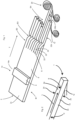
- FIG. 1 shows a schematic representation to illustrate the procedure according to the invention.
- a foam carrier 2 with a surface 2c is transported in a transport direction T in an area B1.
- This transport direction T also corresponds to the longitudinal direction of the sealing tape to be produced later.
- This surface is processed with a processing device 6 (shown only schematically).
- this is a heating device that heats the foam carrier 2 and, in particular, melts it in sections.
- This processing device 6 can be designed as a heated roller which contacts said surface of the foam carrier 2 . However, it could also be heating devices such as infrared elements, which are arranged slightly above the foam carrier and heat it.
- a self-skin 8 is formed on the surface 2c, d. H.
- the foam carrier now has different physical properties on this very surface 2c than on its other surfaces.
- the foam carrier also has other physical properties on this very surface 2c than in its interior.
- a coating (not shown) to the surface 2d (not shown) opposite the surface 2c.
- a coating could for example be glued to this opposite surface.
- Such a coating could be a sheet unwound from a roll (not shown) and applied to the opposite surface.
- this surface 2d it would also be possible for this surface 2d to also be processed and in particular heated in order to achieve a skin on this side as well.
- a multiplicity of cuts S are made in the foam carrier 2, which has already been provided with the coating 14. These cuts are parallel to one another and also extend in the transport direction T. These cuts produce a large number of strips 22, 24, 26 which are parallel to one another and which extend in the transport direction T.
- these individual strips are each rotated counterclockwise by 90°, so that the surfaces provided with the self-skin 8 each point to the right, viewed in the transport direction. If a coating or skin is applied to the opposite surface 2d, a corresponding coating or skin would also be present on the left-hand surface viewed in the direction of transport after rotation.
- an adhesive layer 12 is attached to the underside of the individual cut strips. It is possible that the strips are already compressed onto these adhesive layers.
- the individual sealing tapes are then rolled up (not shown) onto a sealing tape roll 20.
- Reference numerals 22b and 24b identify two surfaces on which the coating is arranged.
- FIG. 2 shows a schematic representation of a sealing tape 1 in an unrolled, ie freely fully expanded state.
- This sealing tape has a longitudinal direction L, as well as a width direction B perpendicular to this longitudinal direction L and a thickness direction D.
- Reference number 2c refers to a surface of the sealing tape which has the skin 8 .
- a coating or skin could also be arranged on the rear surface 2d.
- the skin 8 on the side surface 2c and the optionally present coating or skin on the side surface 2d preferably differ from one another in at least one physical property.
- Numeral 12 denotes an adhesive layer which is arranged on a downwardly facing surface 2b.
- the surface 2a is neither coated nor provided with an adhesive layer.
Claims (11)
- Procédé de fabrication d'une bande d'étanchéité avec les étapes consistant à :- fournir un support en mousse (2) et transporter celui-ci dans un sens de transport (T) prédéfini,- traiter une première surface du support en mousse,- couper ce support en mousse au moins en deux et de préférence en une pluralité de bandes (22, 24, 26),- monter un autocollant au niveau d'une autre surface (22b, 24b, 26b, 28b) des bandes individuelles,caractérisé en ce que
le traitement de la surface du support en mousse contient au moins un chauffage de cette surface. - Procédé selon la revendication 1,
caractérisé en ce que
une part prédéfinie de l'épaisseur du support en mousse est fondue par le chauffage. - Procédé selon au moins l'une quelconque des revendications précédentes,
caractérisé en ce que
la première surface est traitée avec une température qui est supérieure à 100 °C. - Procédé selon au moins l'une quelconque des revendications précédentes,
caractérisé en ce que
le traitement est effectué par contact du support en mousse avec un dispositif de rouleau chauffé. - Procédé selon au moins l'une quelconque des revendications précédentes,
caractérisé en ce que
une épaisseur du support en mousse (2) est réduite d'au moins 0,3 cm par le traitement de la surface. - Procédé selon la revendication 1,
caractérisé en ce que
le support en mousse est un support en mousse (2) imprégné. - Procédé selon au moins l'une quelconque des revendications précédentes,
caractérisé en ce que
le traitement de la surface est entrepris au niveau d'un support en mousse imprégné et séché ou au niveau d'une mousse non imprégnée. - Procédé selon au moins l'une quelconque des revendications précédentes,
caractérisé en ce que
les bandes (22, 24, 26) sont tournées respectivement par rapport au sens de transport et sont de préférence tournées de 90° par rapport au sens de transport. - Procédé selon au moins l'une quelconque des revendications précédentes,
caractérisé en ce que
les bandes sont enroulées au moins partiellement, dans lequel de préférence pendant ce processus d'enroulement, les bandes sont comprimées dans au moins un sens. - Bande d'étanchéité confectionnée comme rouleau de bande d'étanchéité qui s'étend dans un premier sens longitudinal (L) et dans un sens de la largeur perpendiculaire à ce sens longitudinal (L), dans laquelle cette bande d'étanchéité présente une première surface (2a) qui s'étend dans ce sens longitudinal (L) ainsi que le sens de la largeur (B) et une deuxième surface (2b) qui fait face à la première surface (2a), dans lequel une couche de colle est agencée au niveau d'une de ces deux surfaces (2a, 2b) et avec une troisième surface (2c) qui s'étend dans le sens longitudinal (L) ainsi que dans un sens de l'épaisseur (D) de la bande d'étanchéité (1) et une quatrième surface (2d) qui fait face à la troisième surface (2c) et qui s'étend aussi dans le sens longitudinal (L) et le sens de l'épaisseur (D),
caractérisée en ce que
la troisième surface (2c) et/ou la quatrième surface (2d) est une surface traitée par un processus de chauffage. - Bande d'étanchéité selon la revendication 10,
caractérisée en ce que
la bande d'étanchéité est enroulée dans un état comprimé dans le sens de l'épaisseur (D).
Applications Claiming Priority (1)
| Application Number | Priority Date | Filing Date | Title |
|---|---|---|---|
| DE102018118854.4A DE102018118854A1 (de) | 2018-08-02 | 2018-08-02 | Herstellungsverfahren für Dichtband und Dichtband |
Publications (2)
| Publication Number | Publication Date |
|---|---|
| EP3603941A1 EP3603941A1 (fr) | 2020-02-05 |
| EP3603941B1 true EP3603941B1 (fr) | 2023-04-05 |
Family
ID=67658427
Family Applications (1)
| Application Number | Title | Priority Date | Filing Date |
|---|---|---|---|
| EP19189783.4A Active EP3603941B1 (fr) | 2018-08-02 | 2019-08-02 | Procédé de fabrication pour une bande d'étanchéité et bande d'étanchéité |
Country Status (3)
| Country | Link |
|---|---|
| EP (1) | EP3603941B1 (fr) |
| DE (1) | DE102018118854A1 (fr) |
| PL (1) | PL3603941T3 (fr) |
Citations (18)
| Publication number | Priority date | Publication date | Assignee | Title |
|---|---|---|---|---|
| DE2112242A1 (de) | 1971-03-13 | 1972-10-12 | Molan Werk Kunststoff Fabrik E | Verfahren und Vorrichtung zum UEberziehen von Schaumstoff-Profilstreifen mit einer Haut |
| DE3133271A1 (de) | 1981-08-22 | 1983-03-03 | Irbit Holding AG, 1701 Fribourg | Zu einer rolle aufgewickelter schaumstoff-streifen, vorzugsweise zu abdichtungszwecken |
| DE3544277C1 (de) | 1985-12-14 | 1987-04-02 | Irbit Res & Consulting Ag | Dichtungsstreifen |
| DE102006043050A1 (de) | 2006-01-19 | 2007-07-26 | Tremco Illbruck Produktion Gmbh | Zur Abdichtung eines Fensterrahmens geeigneter Schaumstoff-Dichtstreifen sowie zum Einbau vorbereiteter Fensterrahmen |
| EP1936246A1 (fr) | 2006-12-18 | 2008-06-25 | ISO-Chemie GmbH | Bande en mousse et sa méthode de fabrication |
| EP2107176A1 (fr) | 2008-03-31 | 2009-10-07 | ISO-Chemie GmbH | Bande d'étanchéité en mousse douce |
| EP2554773A2 (fr) | 2011-08-04 | 2013-02-06 | Tremco illbruck Produktion GmbH | Bande d'étanchéité pour joint ainsi que construction dotée de cette bande d'étanchéité |
| DE202012103636U1 (de) | 2012-09-21 | 2014-01-02 | Tremco Illbruck Produktion Gmbh | Dichtband und Wandaufbau mit solchem |
| EP2733271A1 (fr) | 2012-11-19 | 2014-05-21 | Tremco illbruck Produktion GmbH | Bâtiment à ventilation forcée doté d'une structure de mur comprenant une bande d'étanchéité |
| EP2851478A1 (fr) | 2013-09-18 | 2015-03-25 | Tremco illbruck Produktion GmbH | Bande d'étanchéité |
| EP2990551A1 (fr) | 2014-08-26 | 2016-03-02 | ISO-Chemie GmbH | Procédé de fabrication d'une bande d'étanchéité |
| EP2990552A1 (fr) | 2014-08-26 | 2016-03-02 | ISO-Chemie GmbH | Procédé de fabrication d'un rouleau de bande d'étanchéité et rouleau de bande d'étanchéité |
| EP2990553A1 (fr) | 2014-08-26 | 2016-03-02 | ISO-Chemie GmbH | Procédé de fabrication d'une bande d'étanchéité |
| EP2990575A1 (fr) | 2014-08-26 | 2016-03-02 | ISO-Chemie GmbH | Bande étanche pour l'étanchéification d'un joint |
| EP3278967A1 (fr) | 2016-08-01 | 2018-02-07 | tremco illbruck Produktion GmbH | Procédé et dispositif de fabrication d'une bande d'étanchéité et bande d'étanchéité avec un support de base |
| EP3404156A1 (fr) | 2017-05-18 | 2018-11-21 | tremco illbruck GmbH | Procédé de fabrication pour une bande d'étanchéité et bande d'étanchéité |
| EP3450642A1 (fr) | 2017-09-01 | 2019-03-06 | ISO-Chemie GmbH | Élément d'étanchéité et procédé de fabrication d'un rouleau de ruban d'étanchéité |
| EP3567174A1 (fr) | 2018-05-07 | 2019-11-13 | ISO-Chemie GmbH | Procédé de fabrication de rouleaux de bandes d'étanchéité |
-
2018
- 2018-08-02 DE DE102018118854.4A patent/DE102018118854A1/de active Pending
-
2019
- 2019-08-02 EP EP19189783.4A patent/EP3603941B1/fr active Active
- 2019-08-02 PL PL19189783.4T patent/PL3603941T3/pl unknown
Patent Citations (22)
| Publication number | Priority date | Publication date | Assignee | Title |
|---|---|---|---|---|
| DE2112242A1 (de) | 1971-03-13 | 1972-10-12 | Molan Werk Kunststoff Fabrik E | Verfahren und Vorrichtung zum UEberziehen von Schaumstoff-Profilstreifen mit einer Haut |
| DE3133271A1 (de) | 1981-08-22 | 1983-03-03 | Irbit Holding AG, 1701 Fribourg | Zu einer rolle aufgewickelter schaumstoff-streifen, vorzugsweise zu abdichtungszwecken |
| DE3544277C1 (de) | 1985-12-14 | 1987-04-02 | Irbit Res & Consulting Ag | Dichtungsstreifen |
| DE102006043050A1 (de) | 2006-01-19 | 2007-07-26 | Tremco Illbruck Produktion Gmbh | Zur Abdichtung eines Fensterrahmens geeigneter Schaumstoff-Dichtstreifen sowie zum Einbau vorbereiteter Fensterrahmen |
| EP1936246A1 (fr) | 2006-12-18 | 2008-06-25 | ISO-Chemie GmbH | Bande en mousse et sa méthode de fabrication |
| EP2107176A1 (fr) | 2008-03-31 | 2009-10-07 | ISO-Chemie GmbH | Bande d'étanchéité en mousse douce |
| EP2554773A2 (fr) | 2011-08-04 | 2013-02-06 | Tremco illbruck Produktion GmbH | Bande d'étanchéité pour joint ainsi que construction dotée de cette bande d'étanchéité |
| DE202012103636U1 (de) | 2012-09-21 | 2014-01-02 | Tremco Illbruck Produktion Gmbh | Dichtband und Wandaufbau mit solchem |
| EP2733271A1 (fr) | 2012-11-19 | 2014-05-21 | Tremco illbruck Produktion GmbH | Bâtiment à ventilation forcée doté d'une structure de mur comprenant une bande d'étanchéité |
| EP2851478A1 (fr) | 2013-09-18 | 2015-03-25 | Tremco illbruck Produktion GmbH | Bande d'étanchéité |
| EP2990551A1 (fr) | 2014-08-26 | 2016-03-02 | ISO-Chemie GmbH | Procédé de fabrication d'une bande d'étanchéité |
| EP2990552A1 (fr) | 2014-08-26 | 2016-03-02 | ISO-Chemie GmbH | Procédé de fabrication d'un rouleau de bande d'étanchéité et rouleau de bande d'étanchéité |
| EP2990553A1 (fr) | 2014-08-26 | 2016-03-02 | ISO-Chemie GmbH | Procédé de fabrication d'une bande d'étanchéité |
| EP2990575A1 (fr) | 2014-08-26 | 2016-03-02 | ISO-Chemie GmbH | Bande étanche pour l'étanchéification d'un joint |
| US20160060863A1 (en) | 2014-08-26 | 2016-03-03 | Iso-Chemie Gmbh | Sealing Tape for Sealing a Joint |
| US20160060068A1 (en) | 2014-08-26 | 2016-03-03 | Iso-Chemie Gmbh | Method for the production of a sealing tape roll |
| US20160059536A1 (en) | 2014-08-26 | 2016-03-03 | Iso-Chemie Gmbh | Method for the production of a sealing tape roll |
| EP3278967A1 (fr) | 2016-08-01 | 2018-02-07 | tremco illbruck Produktion GmbH | Procédé et dispositif de fabrication d'une bande d'étanchéité et bande d'étanchéité avec un support de base |
| EP3404156A1 (fr) | 2017-05-18 | 2018-11-21 | tremco illbruck GmbH | Procédé de fabrication pour une bande d'étanchéité et bande d'étanchéité |
| EP3450642A1 (fr) | 2017-09-01 | 2019-03-06 | ISO-Chemie GmbH | Élément d'étanchéité et procédé de fabrication d'un rouleau de ruban d'étanchéité |
| EP3450643A1 (fr) | 2017-09-01 | 2019-03-06 | ISO-Chemie GmbH | Rouleau de bande d'étanchéité |
| EP3567174A1 (fr) | 2018-05-07 | 2019-11-13 | ISO-Chemie GmbH | Procédé de fabrication de rouleaux de bandes d'étanchéité |
Also Published As
| Publication number | Publication date |
|---|---|
| DE102018118854A1 (de) | 2020-02-06 |
| EP3603941A1 (fr) | 2020-02-05 |
| PL3603941T3 (pl) | 2023-08-07 |
Similar Documents
| Publication | Publication Date | Title |
|---|---|---|
| EP2990551B1 (fr) | Procédé de fabrication d'un rouleau de ruban étanche | |
| EP2990552B1 (fr) | Procédé de fabrication d'un rouleau de bande d'étanchéité et rouleau de bande d'étanchéité | |
| EP3404156B1 (fr) | Procédé de fabrication pour une bande d'étanchéité | |
| EP3278967B1 (fr) | Procédé et dispositif de fabrication d'une bande d'étanchéité | |
| EP3567177B1 (fr) | Procédé de fabrication de rouleaux de bandes d'étanchéité | |
| EP3450643B2 (fr) | Rouleau de bande d'étanchéité | |
| EP3603941B1 (fr) | Procédé de fabrication pour une bande d'étanchéité et bande d'étanchéité | |
| EP3757306A1 (fr) | Bande d'étanchéité | |
| DE102019100686B4 (de) | Verfahren und Vorrichtung zur Herstellung eines Dichtbandes | |
| EP4045726A1 (fr) | Bande d'étanchéité pour étanchéifier des joints de structure | |
| DE102018123809A1 (de) | Verfahren zur Herstellung eines Schaumstoffdichtbandes und Schaumstoffdichtband | |
| DE102018123811A1 (de) | Verfahren zur Herstellung eines Schaumstoffdichtbandes und Schaumstoffdichtband | |
| EP3608482B1 (fr) | Procédé de fabrication d'un rouleau de ruban d'étanchéité | |
| EP3680304A1 (fr) | Procédé et dispositif de fabrication d'une bande d'étanchéité et bande d'étanchéité | |
| EP3848427A1 (fr) | Procédé et dispositif de fabrication d'une bande d'étanchéité et bande d'étanchéité | |
| DE102019009088A1 (de) | Verfahren und Vorrichtung zur Herstellung eines Dichtbandes und Dichtband | |
| DE102018127312A1 (de) | Verfahren zur Herstellung eines Schaumstoffdichtbandes und Schaumstoffdichtband | |
| DE202018107177U1 (de) | Dichtband mit Trennschicht | |
| EP3702427A1 (fr) | Feuilles revêtues d'adhésif sur deux côtés | |
| DE102020132214A1 (de) | Dichtband mit zwei Schaumstoffstreifen |
Legal Events
| Date | Code | Title | Description |
|---|---|---|---|
| PUAI | Public reference made under article 153(3) epc to a published international application that has entered the european phase |
Free format text: ORIGINAL CODE: 0009012 |
|
| STAA | Information on the status of an ep patent application or granted ep patent |
Free format text: STATUS: THE APPLICATION HAS BEEN PUBLISHED |
|
| AK | Designated contracting states |
Kind code of ref document: A1 Designated state(s): AL AT BE BG CH CY CZ DE DK EE ES FI FR GB GR HR HU IE IS IT LI LT LU LV MC MK MT NL NO PL PT RO RS SE SI SK SM TR |
|
| AX | Request for extension of the european patent |
Extension state: BA ME |
|
| STAA | Information on the status of an ep patent application or granted ep patent |
Free format text: STATUS: REQUEST FOR EXAMINATION WAS MADE |
|
| 17P | Request for examination filed |
Effective date: 20200804 |
|
| RBV | Designated contracting states (corrected) |
Designated state(s): AL AT BE BG CH CY CZ DE DK EE ES FI FR GB GR HR HU IE IS IT LI LT LU LV MC MK MT NL NO PL PT RO RS SE SI SK SM TR |
|
| RAP1 | Party data changed (applicant data changed or rights of an application transferred) |
Owner name: TREMCO CPG GERMANY GMBH |
|
| STAA | Information on the status of an ep patent application or granted ep patent |
Free format text: STATUS: EXAMINATION IS IN PROGRESS |
|
| STAA | Information on the status of an ep patent application or granted ep patent |
Free format text: STATUS: EXAMINATION IS IN PROGRESS |
|
| 17Q | First examination report despatched |
Effective date: 20210112 |
|
| GRAP | Despatch of communication of intention to grant a patent |
Free format text: ORIGINAL CODE: EPIDOSNIGR1 |
|
| STAA | Information on the status of an ep patent application or granted ep patent |
Free format text: STATUS: GRANT OF PATENT IS INTENDED |
|
| RIC1 | Information provided on ipc code assigned before grant |
Ipc: B29K 105/04 20060101ALN20221024BHEP Ipc: E06B 1/62 20060101ALI20221024BHEP Ipc: E04B 1/68 20060101ALI20221024BHEP Ipc: B29C 67/20 20060101AFI20221024BHEP |
|
| INTG | Intention to grant announced |
Effective date: 20221108 |
|
| GRAS | Grant fee paid |
Free format text: ORIGINAL CODE: EPIDOSNIGR3 |
|
| GRAA | (expected) grant |
Free format text: ORIGINAL CODE: 0009210 |
|
| STAA | Information on the status of an ep patent application or granted ep patent |
Free format text: STATUS: THE PATENT HAS BEEN GRANTED |
|
| AK | Designated contracting states |
Kind code of ref document: B1 Designated state(s): AL AT BE BG CH CY CZ DE DK EE ES FI FR GB GR HR HU IE IS IT LI LT LU LV MC MK MT NL NO PL PT RO RS SE SI SK SM TR |
|
| REG | Reference to a national code |
Ref country code: GB Ref legal event code: FG4D Free format text: NOT ENGLISH |
|
| REG | Reference to a national code |
Ref country code: DE Ref legal event code: R096 Ref document number: 502019007380 Country of ref document: DE |
|
| REG | Reference to a national code |
Ref country code: CH Ref legal event code: EP |
|
| REG | Reference to a national code |
Ref country code: AT Ref legal event code: REF Ref document number: 1557917 Country of ref document: AT Kind code of ref document: T Effective date: 20230415 |
|
| REG | Reference to a national code |
Ref country code: IE Ref legal event code: FG4D Free format text: LANGUAGE OF EP DOCUMENT: GERMAN |
|
| P01 | Opt-out of the competence of the unified patent court (upc) registered |
Effective date: 20230520 |
|
| REG | Reference to a national code |
Ref country code: LT Ref legal event code: MG9D |
|
| REG | Reference to a national code |
Ref country code: NL Ref legal event code: MP Effective date: 20230405 |
|
| PG25 | Lapsed in a contracting state [announced via postgrant information from national office to epo] |
Ref country code: NL Free format text: LAPSE BECAUSE OF FAILURE TO SUBMIT A TRANSLATION OF THE DESCRIPTION OR TO PAY THE FEE WITHIN THE PRESCRIBED TIME-LIMIT Effective date: 20230405 |
|
| PG25 | Lapsed in a contracting state [announced via postgrant information from national office to epo] |
Ref country code: SE Free format text: LAPSE BECAUSE OF FAILURE TO SUBMIT A TRANSLATION OF THE DESCRIPTION OR TO PAY THE FEE WITHIN THE PRESCRIBED TIME-LIMIT Effective date: 20230405 Ref country code: PT Free format text: LAPSE BECAUSE OF FAILURE TO SUBMIT A TRANSLATION OF THE DESCRIPTION OR TO PAY THE FEE WITHIN THE PRESCRIBED TIME-LIMIT Effective date: 20230807 Ref country code: NO Free format text: LAPSE BECAUSE OF FAILURE TO SUBMIT A TRANSLATION OF THE DESCRIPTION OR TO PAY THE FEE WITHIN THE PRESCRIBED TIME-LIMIT Effective date: 20230705 Ref country code: ES Free format text: LAPSE BECAUSE OF FAILURE TO SUBMIT A TRANSLATION OF THE DESCRIPTION OR TO PAY THE FEE WITHIN THE PRESCRIBED TIME-LIMIT Effective date: 20230405 |
|
| PGFP | Annual fee paid to national office [announced via postgrant information from national office to epo] |
Ref country code: CZ Payment date: 20230721 Year of fee payment: 5 Ref country code: CH Payment date: 20230902 Year of fee payment: 5 |
|
| PG25 | Lapsed in a contracting state [announced via postgrant information from national office to epo] |
Ref country code: RS Free format text: LAPSE BECAUSE OF FAILURE TO SUBMIT A TRANSLATION OF THE DESCRIPTION OR TO PAY THE FEE WITHIN THE PRESCRIBED TIME-LIMIT Effective date: 20230405 Ref country code: LV Free format text: LAPSE BECAUSE OF FAILURE TO SUBMIT A TRANSLATION OF THE DESCRIPTION OR TO PAY THE FEE WITHIN THE PRESCRIBED TIME-LIMIT Effective date: 20230405 Ref country code: LT Free format text: LAPSE BECAUSE OF FAILURE TO SUBMIT A TRANSLATION OF THE DESCRIPTION OR TO PAY THE FEE WITHIN THE PRESCRIBED TIME-LIMIT Effective date: 20230405 Ref country code: IS Free format text: LAPSE BECAUSE OF FAILURE TO SUBMIT A TRANSLATION OF THE DESCRIPTION OR TO PAY THE FEE WITHIN THE PRESCRIBED TIME-LIMIT Effective date: 20230805 Ref country code: HR Free format text: LAPSE BECAUSE OF FAILURE TO SUBMIT A TRANSLATION OF THE DESCRIPTION OR TO PAY THE FEE WITHIN THE PRESCRIBED TIME-LIMIT Effective date: 20230405 Ref country code: GR Free format text: LAPSE BECAUSE OF FAILURE TO SUBMIT A TRANSLATION OF THE DESCRIPTION OR TO PAY THE FEE WITHIN THE PRESCRIBED TIME-LIMIT Effective date: 20230706 Ref country code: AL Free format text: LAPSE BECAUSE OF FAILURE TO SUBMIT A TRANSLATION OF THE DESCRIPTION OR TO PAY THE FEE WITHIN THE PRESCRIBED TIME-LIMIT Effective date: 20230405 |
|
| PGFP | Annual fee paid to national office [announced via postgrant information from national office to epo] |
Ref country code: PL Payment date: 20230721 Year of fee payment: 5 Ref country code: FR Payment date: 20230822 Year of fee payment: 5 |
|
| PG25 | Lapsed in a contracting state [announced via postgrant information from national office to epo] |
Ref country code: FI Free format text: LAPSE BECAUSE OF FAILURE TO SUBMIT A TRANSLATION OF THE DESCRIPTION OR TO PAY THE FEE WITHIN THE PRESCRIBED TIME-LIMIT Effective date: 20230405 |
|
| REG | Reference to a national code |
Ref country code: DE Ref legal event code: R026 Ref document number: 502019007380 Country of ref document: DE |
|
| PLBI | Opposition filed |
Free format text: ORIGINAL CODE: 0009260 |
|
| PG25 | Lapsed in a contracting state [announced via postgrant information from national office to epo] |
Ref country code: SK Free format text: LAPSE BECAUSE OF FAILURE TO SUBMIT A TRANSLATION OF THE DESCRIPTION OR TO PAY THE FEE WITHIN THE PRESCRIBED TIME-LIMIT Effective date: 20230405 |
|
| PLAX | Notice of opposition and request to file observation + time limit sent |
Free format text: ORIGINAL CODE: EPIDOSNOBS2 |
|
| PG25 | Lapsed in a contracting state [announced via postgrant information from national office to epo] |
Ref country code: SM Free format text: LAPSE BECAUSE OF FAILURE TO SUBMIT A TRANSLATION OF THE DESCRIPTION OR TO PAY THE FEE WITHIN THE PRESCRIBED TIME-LIMIT Effective date: 20230405 Ref country code: SK Free format text: LAPSE BECAUSE OF FAILURE TO SUBMIT A TRANSLATION OF THE DESCRIPTION OR TO PAY THE FEE WITHIN THE PRESCRIBED TIME-LIMIT Effective date: 20230405 Ref country code: RO Free format text: LAPSE BECAUSE OF FAILURE TO SUBMIT A TRANSLATION OF THE DESCRIPTION OR TO PAY THE FEE WITHIN THE PRESCRIBED TIME-LIMIT Effective date: 20230405 Ref country code: EE Free format text: LAPSE BECAUSE OF FAILURE TO SUBMIT A TRANSLATION OF THE DESCRIPTION OR TO PAY THE FEE WITHIN THE PRESCRIBED TIME-LIMIT Effective date: 20230405 Ref country code: DK Free format text: LAPSE BECAUSE OF FAILURE TO SUBMIT A TRANSLATION OF THE DESCRIPTION OR TO PAY THE FEE WITHIN THE PRESCRIBED TIME-LIMIT Effective date: 20230405 |
|
| PGFP | Annual fee paid to national office [announced via postgrant information from national office to epo] |
Ref country code: DE Payment date: 20231018 Year of fee payment: 5 |
|
| 26 | Opposition filed |
Opponent name: ISO-CHEMIE GMBH Effective date: 20240102 |
|
| PG25 | Lapsed in a contracting state [announced via postgrant information from national office to epo] |
Ref country code: MC Free format text: LAPSE BECAUSE OF FAILURE TO SUBMIT A TRANSLATION OF THE DESCRIPTION OR TO PAY THE FEE WITHIN THE PRESCRIBED TIME-LIMIT Effective date: 20230405 |
|
| PG25 | Lapsed in a contracting state [announced via postgrant information from national office to epo] |
Ref country code: MC Free format text: LAPSE BECAUSE OF FAILURE TO SUBMIT A TRANSLATION OF THE DESCRIPTION OR TO PAY THE FEE WITHIN THE PRESCRIBED TIME-LIMIT Effective date: 20230405 |
|
| PG25 | Lapsed in a contracting state [announced via postgrant information from national office to epo] |
Ref country code: LU Free format text: LAPSE BECAUSE OF NON-PAYMENT OF DUE FEES Effective date: 20230802 |
|
| GBPC | Gb: european patent ceased through non-payment of renewal fee |
Effective date: 20230802 |