EP2990552B1 - Method for producing a sealing tape roll and sealing tape roll - Google Patents
Method for producing a sealing tape roll and sealing tape roll Download PDFInfo
- Publication number
- EP2990552B1 EP2990552B1 EP14182233.8A EP14182233A EP2990552B1 EP 2990552 B1 EP2990552 B1 EP 2990552B1 EP 14182233 A EP14182233 A EP 14182233A EP 2990552 B1 EP2990552 B1 EP 2990552B1
- Authority
- EP
- European Patent Office
- Prior art keywords
- foam
- web
- barrier layer
- strip
- strips
- Prior art date
- Legal status (The legal status is an assumption and is not a legal conclusion. Google has not performed a legal analysis and makes no representation as to the accuracy of the status listed.)
- Active
Links
- 238000007789 sealing Methods 0.000 title claims description 88
- 238000004519 manufacturing process Methods 0.000 title claims description 19
- 239000006260 foam Substances 0.000 claims description 280
- 230000004888 barrier function Effects 0.000 claims description 113
- 238000000034 method Methods 0.000 claims description 25
- 239000002390 adhesive tape Substances 0.000 claims description 14
- 238000004804 winding Methods 0.000 claims description 5
- 238000001035 drying Methods 0.000 claims description 3
- 239000000126 substance Substances 0.000 claims description 2
- 239000010410 layer Substances 0.000 description 109
- 238000005470 impregnation Methods 0.000 description 8
- 239000000853 adhesive Substances 0.000 description 7
- 230000001070 adhesive effect Effects 0.000 description 7
- 238000005520 cutting process Methods 0.000 description 7
- 239000006261 foam material Substances 0.000 description 6
- 238000009434 installation Methods 0.000 description 6
- 230000006835 compression Effects 0.000 description 4
- 238000007906 compression Methods 0.000 description 4
- 238000009792 diffusion process Methods 0.000 description 4
- 238000003475 lamination Methods 0.000 description 4
- 230000003111 delayed effect Effects 0.000 description 3
- 238000010438 heat treatment Methods 0.000 description 3
- 239000000463 material Substances 0.000 description 3
- 238000011084 recovery Methods 0.000 description 3
- 238000003860 storage Methods 0.000 description 3
- XLYOFNOQVPJJNP-UHFFFAOYSA-N water Chemical compound O XLYOFNOQVPJJNP-UHFFFAOYSA-N 0.000 description 3
- 238000004026 adhesive bonding Methods 0.000 description 2
- 239000012790 adhesive layer Substances 0.000 description 2
- 238000005304 joining Methods 0.000 description 2
- 238000003698 laser cutting Methods 0.000 description 2
- -1 polyethylene Polymers 0.000 description 2
- 238000003825 pressing Methods 0.000 description 2
- 241001136792 Alle Species 0.000 description 1
- 206010013786 Dry skin Diseases 0.000 description 1
- 239000004831 Hot glue Substances 0.000 description 1
- 239000004698 Polyethylene Substances 0.000 description 1
- 239000004743 Polypropylene Substances 0.000 description 1
- 238000010521 absorption reaction Methods 0.000 description 1
- 239000011248 coating agent Substances 0.000 description 1
- 238000000576 coating method Methods 0.000 description 1
- 230000000694 effects Effects 0.000 description 1
- 239000004744 fabric Substances 0.000 description 1
- 239000007788 liquid Substances 0.000 description 1
- 230000033001 locomotion Effects 0.000 description 1
- 238000002156 mixing Methods 0.000 description 1
- 239000004745 nonwoven fabric Substances 0.000 description 1
- 229920000573 polyethylene Polymers 0.000 description 1
- 229920001155 polypropylene Polymers 0.000 description 1
- 229920002635 polyurethane Polymers 0.000 description 1
- 239000004814 polyurethane Substances 0.000 description 1
- 229920000915 polyvinyl chloride Polymers 0.000 description 1
- 239000004800 polyvinyl chloride Substances 0.000 description 1
- 239000011148 porous material Substances 0.000 description 1
- 238000005096 rolling process Methods 0.000 description 1
- 238000007493 shaping process Methods 0.000 description 1
- 238000004904 shortening Methods 0.000 description 1
- 239000007787 solid Substances 0.000 description 1
- 238000007711 solidification Methods 0.000 description 1
- 230000008023 solidification Effects 0.000 description 1
- 239000004834 spray adhesive Substances 0.000 description 1
- 239000004753 textile Substances 0.000 description 1
- 230000007704 transition Effects 0.000 description 1
Images

Classifications
-
- E—FIXED CONSTRUCTIONS
- E04—BUILDING
- E04B—GENERAL BUILDING CONSTRUCTIONS; WALLS, e.g. PARTITIONS; ROOFS; FLOORS; CEILINGS; INSULATION OR OTHER PROTECTION OF BUILDINGS
- E04B1/00—Constructions in general; Structures which are not restricted either to walls, e.g. partitions, or floors or ceilings or roofs
- E04B1/62—Insulation or other protection; Elements or use of specified material therefor
- E04B1/66—Sealings
- E04B1/68—Sealings of joints, e.g. expansion joints
- E04B1/6812—Compressable seals of solid form
-
- E—FIXED CONSTRUCTIONS
- E06—DOORS, WINDOWS, SHUTTERS, OR ROLLER BLINDS IN GENERAL; LADDERS
- E06B—FIXED OR MOVABLE CLOSURES FOR OPENINGS IN BUILDINGS, VEHICLES, FENCES OR LIKE ENCLOSURES IN GENERAL, e.g. DOORS, WINDOWS, BLINDS, GATES
- E06B1/00—Border constructions of openings in walls, floors, or ceilings; Frames to be rigidly mounted in such openings
- E06B1/62—Tightening or covering joints between the border of openings and the frame or between contiguous frames
- E06B2001/626—Tightening or covering joints between the border of openings and the frame or between contiguous frames comprising expanding foam strips
Definitions
- the present invention relates to a method for producing a sealing tape roll.
- sealing tapes are commonly used for sealing joints, for example, between a frame profile of a window or a door and a building wall to seal the joints against draft and driving rain. Additionally provided films on a side surface of the sealing tape also increase the vapor impermeability of the same, see, for example EP 0 072 955 A1 or EP 1 936 246 A1 , However, films which are attached to the outside of the sealing tape, have the disadvantage that they can be damaged during transport or installation of the sealing tape.
- a sealing strip roll which has at least one barrier layer extending in the radial direction, which is arranged between two layers of the foam and thus in the interior of the sealing strip roll.
- the barrier layer consists of adhesive or of a lamination material.
- large-area barrier layers are formed on plates of an open-pore foam material by lamination or gluing. Multiple layers of foam boards and barrier layers form laminate blocks. These laminate blocks are separated into sheets orthogonal to the large-area barrier layers.
- the panels are then wound into wide rollers such that the barrier layers and the foam material are lined up on the circumference of the rollers in the axial direction. Such a wide roll is then separated between the individual barrier layers into slices to form several sealing tape rolls. This method requires many complex steps and the length of the sealing strips produced is limited by the size limitation of automatically machinable laminate blocks.
- the EP 2 620 565 A1 discloses a sealing tape in which a barrier layer in the form of a film-like strip having a U- or V-shape is introduced into the sealing tape.
- a barrier layer in the form of a film-like strip having a U- or V-shape is introduced into the sealing tape.
- the DE 20 2012 101 990 U1 describes another foam sealing tape in which a barrier layer can be attached to different portions of the sealing tape or introduced into an incision in the sealing tape. It discloses a method for producing a sealing tape roll having the features of the preamble of claim 1.
- the present invention has for its object to provide a method for producing a roll of a sealing tape having an inner, radially extending barrier layer, wherein the properties of the sealing tape are variably modifiable, and wherein the method is simple and reliable.
- a sealing tape roll made of soft, compressed foam with at least one extending in the radial direction barrier layer to increase the air and vapor impermeability can be produced relatively little effort.
- the barrier layer is protected by the recording between two foam strips from external damage during transport and installation of the sealing strip.
- the properties of the sealing tape particularly variable shaped, since foam strips of any design can be combined.
- the provided first foam sheet is impregnated. In this way, the sealing tape to be produced on a delayed reset.
- the introduction of the at least one continuous cut into the laminated foam web is preferably carried out by means of at least one knife or at least one saw. These are particularly suitable for cutting through the foam web.
- the connecting layer is a double-sided adhesive tape which is laminated on its side facing away from the foam strip with a release liner.
- the first foam strip and the second foam strip can be connected to one another with particularly little effort and without additional connecting means.
- the double-sided adhesive strip can be used directly for attaching the sealing strip to a frame profile of the window.
- a sealing tape roll produced by the method of the invention comprises a wound foam barrier sheet.
- the foam barrier sheet has at least one first soft foam foam strip provided with at least one barrier layer on at least one side and at least one second soft foam foam strip, each barrier layer disposed axially between adjacent foam strips and in the sealing tape roll in the radial direction.
- a common bonding layer is applied to all the foam strips of the foam barrier sheet on a surface perpendicular to each barrier layer, with the tie layer forming the only bond between the foam strips.
- the properties of the sealing strip are particularly variable designable and the sealing tape is still easy to manufacture.
- precisely one first foam strip with exactly one second foam strip forms the foam barrier sheet, with precisely one barrier layer attached to the first foam strip.
- the production of the sealing tape roll is particularly inexpensive.
- precisely one first foam strip with exactly two second foam strips forms the foam barrier sheet, with exactly two barrier layers attached to opposite sides of the first foam strip, and with the first foam strip disposed between the two second foam strips. In this way it is particularly easy to produce an increased sealing effect.
- a plurality of first foam strips having just one second foam strip form the foam barrier sheet with exactly one barrier layer attached to each first foam strip and the second foam strip disposed at an edge of the foam barrier sheet ,
- sealing tapes can be made with any number of alternating foam strips and barrier layers.
- the connecting layer is a double-sided adhesive tape which is laminated on its side facing away from the foam strip with a release liner.
- the foam strips are thus particularly easily and safely connected.
- an adhesive layer for attachment of the sealing strip is provided on a window frame.
- the at least one first foam strip is impregnated.
- the sealing strip to be produced has a delayed return in this area.
- the at least one second foam strip is also impregnated and thus likewise has a delayed recovery.
- the at least one first foam strip is made of a different foam material than the at least one second foam strip. In this way, the properties of the sealing tape can be made very variable and easy to influence.
- the at least one first foam strip may have a different color than the at least one second foam strip.
- the denser side of the sealing band can be identified, which generally faces the interior of the room, and thus the assembly can be simplified.
- a soft foam in the form of a wound-up first foam sheet 20 is provided on a first roll 10.
- the soft foam is provided on the first roll 10 in long lengths of up to 200 meters, preferably between 5 and 100 meters, more preferably between 10 and 60 meters.
- foams it is possible to use all known open-cell, mixed-cell or closed-cell flexible foams made of, for example, polyurethane, polyethylene, polyvinyl chloride or polypropylene used, which make a provision after compression.
- the first foam sheet 20 may already be impregnated before further processing, but is preferably not yet impregnated.
- the foam sheet 20 can be particularly well transported and processed.
- the foam web 20 is located on the first roller 10 in an un-compressed or only slightly compressed state. It is also possible for the foam web 20 to be in a compressed state on the first roll 10, but then, after unwinding from the first roll 10, a timely recovery of the foam material in the process flow must be ensured.
- the width of the foam web 20 is usually between 1 cm and 5 m, preferably between 1.0 m and 1.5 m.
- the height of the foam web 20 in the relaxed state is usually between 5 and 150 mm, more preferably between 10 and 80 mm.
- first foam sheets 20 which are not wound on a first roll 10, but which requires a larger supply space.
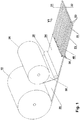
- the first foam sheet 20 After unwinding from the first roller 10, the first foam sheet 20 is moved along a first conveying direction, which is indicated by the arrow V1. Subsequently, a barrier layer 30 is applied to the top 21 of the first foam sheet 20 so as to form a laminated foam sheet 34.
- the barrier layer 30 is formed by a film web which is provided on a film supply roll 26.
- the barrier layer 30 designed as a film web is preferably applied from above onto the upper side 21 of the foam web 20. This is usually done in the region of a connection unit, which is represented schematically by the roller 28.
- the bonding step typically includes generally a step of applying heat and / or a step of pressing the barrier layer 30 and the foam sheet 20 together.
- the connection to the foam web 20 in the connection unit preferably takes place by lamination.
- the barrier layer 30 can also be formed by a web of a single-sided adhesive tape. The adhesive side of the adhesive tape is then usually provided with a peel-off film, which is peeled off shortly before application to the foam web 20. Likewise, the barrier layer 30 may be formed by a film web which itself comprises a layer of adhesive tape or a solid layer of a hotmelt adhesive. Finally, to form the barrier layer 30, an adhesive-like liquid medium may also be applied to the foam sheet 20 by means of nozzles (e.g., melt die, flat die, mixing die) or by roll coating (transfer roll). Depending on the adhesive may then, preferably in a connection unit, take place a connection with the foam sheet 20, wherein the adhesive is usually solidified.
- nozzles e.g., melt die, flat die, mixing die
- transfer roll e.g., transfer roll
- the connection of the barrier layer 30 to the foam sheet 20 will typically again include a step of applying heat and / or a step of pressing the barrier layer 30 and the foam sheet 20 together. It is also possible to apply a spray adhesive on one side of a film web and to use this combination as a barrier layer 30.
- a skin of the foam material of the first foam sheet 20 itself serve when the foam sheet 20 is melted on one side and then re-hardened or if the foam sheet 20 due to production has a skin.
- Each heat application step above is carried out by means of a heating device, which is usually designed as a hot air blower. But it is also radiant heating in question, for example by means of an infrared heater or microwave heating.
- the function of the barrier layer 30 is preferably to reduce or prevent the passage of air and / or water vapor. This also applies to all subsequent embodiments.
- barrier layer 30 may also be attached to the underside 22 of the foam sheet 20 from below. Another embodiment provides for the application of barrier layers 30 on top 21 and bottom 22 of foam sheet 20.
- At least one blade 38 By means of at least one blade 38, preferably a plurality of parallel blades 38, at least one continuous cut 40, preferably several parallel continuous cuts 40, in the laminated foam sheet 34 in the longitudinal direction of the laminated foam sheet 34, preferably parallel to the longitudinal edges 23 of the laminated foam sheet 34 is introduced ,
- the longitudinal edges 23 are the edges of the laminated foam sheet 34, which are parallel to the conveying direction V1 and orthogonal to the axial direction of the first roller 10.
- all other methods known to those skilled in the art for cutting through foam webs 20 can be used, such as saw cutting, heated wires, laser cutting or water jet cutting.
- the continuous cuts 40 create a plurality of first foam strips 50 provided with a barrier layer 30.
- the first foam strips 50 produced by the at least one cut 40 may have a different width, but they are preferably the same width.
- the width of a foam strip 50 is between 5 mm and 30 cm, preferably between 1 and 12 cm.
- the first foam strips 50 may be wound onto a supply roll (not shown) at this point to enable them to be further processed, thus shortening the length of the entire production line, or may be fed directly to further processing. Overall, the number of successive steps in a production line can be varied by the use of supply rolls as a buffer, and thus the length of the individual sections of the production line can be adjusted according to the prevailing space conditions.
- the first foam sheet 20 is first cut into foam strips 50 and the individual foam strips 50 are then equipped with the barrier layers 30.
- the barrier layers 30 may also extend only over part of a side surface of the foam strips 50.
- a film could be used as a barrier layer 30, which adheres only selectively to the foam strip 50 and thus in the compressed state of the sealing tape an expansion reserve, for example in the form of a loop has.
- a barrier layer 30, for example in the form of a film may be arranged over a plurality of side surfaces.
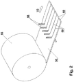
- a second foam web 58 made of soft foam on a second roller 55 is preferably provided uncompressed. After unwinding from the second roller 55, the second foam web 58 is moved along a second conveying direction V2. The same applies to the type of foam as to the foam of the first foam web 20.
- At least one blade 56 By means of at least one blade 56, preferably a plurality of parallel blades 56, at least one continuous cut 59, preferably several parallel continuous cuts 59, is introduced into the second foam web 58 in a direction parallel to the longitudinal edges of the foam web 58.
- the at least one continuous cut 59 thus generates a plurality of second foam strips 60.
- all other methods known to those skilled in the art for cutting foam webs can be used, for example cutting through sawing, heated wires, laser cutting or water jet cutting.
- the second foam strips 60 can be wound up at this point into a supply roll (not shown) or fed directly to further processing.
- the second foam strips 60 may also be provided individually.
- the second foam strips 60, as well as the first foam strips 50 may be provided with at least one barrier layer 30.
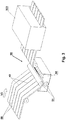
- Fig. 3 shows the optional step of impregnating the laminated foam sheet 34 or the first foam strips 50. Impregnation occurs either prior to the step of introducing the at least one cut 40 into the laminated foam sheet 34, or as shown in FIG Fig. 3 shown after the introduction of the at least one continuous section 40 in the laminated foam sheet 34. In the latter case, it is advantageous if the first foam strips 50 are guided in parallel and simultaneously impregnated.
- the impregnation can also take place before the application of the at least one barrier layer 30 to the foam web 20. Due to the poorer adhesion of the barrier layer 30 on an impregnated foam web 20 and thus difficult connecting the barrier layer 30 with the foam sheet 20, however, the impregnation after the application of the barrier layer 30 is preferable.
- the first foam strips 50 are guided side by side through an impregnation unit 90.
- At least two rollers 91 guide the foam strips 50 into a bath of a suitable impregnate 94 and the foam absorbs itself completely with the impregnate.
- Conventional impregnates and methods for impregnating foams are known to the person skilled in the art.
- the foam strips 50 are compressed between the rollers 91 to promote the absorption of the impregnate 94 by the subsequent recovery of the foam.
- excess impregnate is preferably squeezed out by means of rollers.
- the impregnated foam strips 50 are then dried in a drying unit 100.
- the impregnated foam strips 50 are dried in a known manner, for example by a fan heater or radiant heater. Also at this point the subsequent winding on a supply roll or the continuous feed for further processing is possible.
- the optional impregnation of the second foam sheet 58 or the second foam strips 60 comprises the same steps.
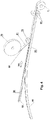
- Fig. 4 shows essential steps of an embodiment of the manufacturing method according to the invention, which is based on the steps Fig. 1 . 2 or 3 can connect.
- the first foam strips 50 provided with at least one barrier layer 30 have already been prefabricated beforehand, for example at another location or by another manufacturer, and within the scope of the inventive method only in this finished form be used.
- a first foam strip 50 and a second foam strip 60 made of soft foam so loosely combined a foam barrier sheeting 70 is formed in which the barrier layer 30 is disposed between the adjoining foam strips 50,60.
- the foam strip 50 is preferably rotated by 90 degrees about its longitudinal axis by means of a suitable deflection device, the longitudinal axis extending along a fourth conveying direction V4.
- the barrier layer 30 is subsequently located on a side surface of the foam strip 50 facing the foam strip 60.
- the first foam strip 50 and the second foam strand 60 are moved together in the conveying direction V4, but are still separated from one another.
- first foam strips 50 may be combined with one or more second foam strips 60, or multiple second foam strips 60 with one or more first foam strips 50.
- the at least one first foam strip 50 may also be provided such that no rotation of the first foam strip 50 is necessary is.
- the at least one second foam strip 60 may be provided such that no rotation of the first foam strip 50 is necessary. It is always important that each provided with a barrier layer 30 side surface of the first foam strip 50 to the adjacent foam strip 50, 60 faces.
- a common tie layer 80 is applied to all of the foam strips 50, 60 of the foam barrier sheeting 70.
- the application of the common bonding layer 80 occurs on a surface of the foam barrier sheeting 70 which is perpendicular to the at least one barrier layer 30.
- the bonding layer 80 is the only strong bond between the foam strips 50, 60 of the foam barrier sheeting 70.
- the tie layer 80 is provided on a supply roll 76 and is applied to the foam barrier sheeting 70 in the region of an application station, here shown schematically by the roll 78, where it is preferably pressed or rolled down.
- Particularly suitable is the use of double-sided adhesive tape as a bonding layer 80.
- This has the advantage that it is easy to apply to the foam barrier layer web 70 and thus at the same time an adhesive surface on the side facing the foam barrier sheeting 70 is provided by means of that's it Sealing tape 2 can be connected during assembly with a frame profile of a window.
- This second adhesive surface of the double-sided adhesive tape on the side facing away from the foam barrier layer web 70 is first laminated with a release liner 81 in order to prevent sticking during further processing.
- the bonding layer 80 it is also possible to use textile fabrics, non-woven fabric layers or other tie-layers which are suitable for joining a plurality of foam strips.
- the connection of the bonding layer 80 to the foam strips 50, 60 preferably takes place by gluing or lamination.
- a sealing tape roll 1 After applying the common bonding layer 80 to all foam strips 50, 60 of the foam barrier sheeting 70, this is compressed to a sealing tape roll 1 wound.
- one or more pairs of compression rollers 84 may be used for the compression.
- a compression roller (not shown) can interact directly with the sealing tape roll when the sealing tape 2 is wound onto the sealing tape roll 1.
- two tie layers 80 may be applied to opposite sides of the foam barrier sheeting 70.
- a foam barrier sheeting 70 is wound from a plurality of foam strips 50, 60 and barrier layers 30 after applying a common tie layer 80 compressed to a wide roll (not shown) that is then joined by at least one knife or at least one knife Saw can be cut to sealing tape rolls 1 desired width.
- the conveying directions V1, V2, V3 and V4 can be identical or different from each other.
- all foam sheets, foam strips or foam barrier sheets are preferably advanced by rolling, more preferably by pairs of counter-rotating rolls. Also treadmills can be used. Such means of locomotion can also be used for the film web or adhesive tape web.
- Fig. 5 shows an installation situation of a sealing tape roll 1 according to Fig. 4 unwound sealing strips 2.
- the sealing strip 2 is first unwind from the sealing strip roll 1 and cut into strips of any length.
- the length of the sealing strip strip is adapted to the outer contours of a sealed window frame or a door frame.
- the sealing tape 2 is then preferably fastened to the window frame 112 or door frame by means of the double-sided adhesive tape acting as a bonding layer 80 or by means of other adhesive layers, adhesive tapes or other suitable means.
- the sealing tape 2 is received between a window frame 112 and masonry 110 to seal the gap between them.
- the illustrated sealing tape 2 in this case comprises a first foam strip 50 provided with a barrier layer 30 and a second foam strip 60.
- the barrier layer 30 is protectively received between the foam strips 50, 60, thereby preventing damage during storage, transportation and storage Assembly of the sealing tape roll 1 and the sealing strip 2 are avoided.
- the sealing strip 2 is to be installed so that at least one barrier layer 30 extends from the window frame 112 to the masonry 110 and thus substantially orthogonal to a functional direction F of the sealing tape 2.
- the functional direction F extends parallel to the surfaces of the window frame 112 and the masonry 110 forming the joint to be sealed from a room outside (in FIG Fig. 5 left) to a room inside (in Fig. 5 right). In this way, a reliable seal against draft and vapor diffusion can be ensured.
- the first foam strip 50 may be made of a different foam material than the second foam strip 60.
- the first foam strips 50 and the second foam strips 60 may be impregnated with different impregnate or only the first foam strips 50 or only the first second foam strip 60 impregnated be.
- the first foam strips 50 may have a different color than the second foam strips 60.
- any number of barrier layers 30 in the sealing tape 2 is possible.
- different widths and / or heights of the first foam strips 50 and / or different widths and / or heights of the second foam strips 60 are conceivable, even within the same sealing strip 2.
- the first or the first foam strips 50 can also have a different width and / or or height than the second foam strip or strips 60.
- the width of the sealing strip 2 is usually between 5 mm and 20 cm, preferably between 1 cm and 12 cm. In the relaxed state, the sealing tape 2 usually has a height of between 5 mm and 30 cm, preferably between 1 and 12 cm.
- FIG. 5 illustrated embodiment forms exactly a first foam strip 50 together with just a second foam strip 60, the foam barrier layer web 70 which is wound into the sealing strip roll 1.
- the foam barrier layer web 70 which is wound into the sealing strip roll 1.
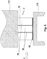
- FIG. 6 Another embodiment is in Fig. 6 shown.
- exactly one first foam strip 50 is brought together with exactly two second foam strips 60 to form the foam barrier web 70, the first foam strip 50 in this case having two barrier layers 30 arranged on opposite sides of the first foam strip 50.
- the first foam strip 50 is disposed between the two second foam strips 60 such that the barrier layers 30 are each disposed between the first foam strip 50 and one of the second foam strips 60.
- the first foam web 20 (FIG. Fig. 1 ) on top 21 and bottom 22 are provided with a barrier layer 30, and then the three foam strips 50, 60 are brought together and bonded together via tie layer 80, similar to FIG Fig. 4 shown.
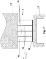
- first foam strips 50 here three first foam strips 50, with exactly one second Foam tabs 60 are joined together to form the foam barrier sheeting 70, with just one barrier layer 30 attached to each first foam strip 50 and with the second foam tab 60 disposed at one edge of the foam barrier sheeting 70.
- the barrier layers 30 are disposed between adjacent foam strips 50, 60.
- the first foam web 20 (FIG. Fig. 1 ) are provided with a barrier layer 30 only on the upper side 21 or the lower side 22, and then the three first foam strips 50 are brought together in a respective 90 ° rotated orientation with the one second foam strip 60 and interconnected via the tie layer 80, similar to FIG Fig. 4 shown.
- foam barrier sheets 70 of any shape can be designed with foam strips 50, 60 and barrier layers 30 preferably alternating in a direction perpendicular to the direction of conveyance V4 and a respective foam strip 50, 60 at one edge of the foam barrier sheet 70 is arranged.
- the connecting layer 80 forms the only connection between the foam strips 50, 60 in the sealing strip 2 and is usually designed as limp, the connecting layer 80 and thus also the sealing strip 2 can be bent at the transition point between individual foam strips 50, 60, which also makes other use variants allows, for example a simultaneous sealing of two joints that abut each other vertically.
- sealing tape 2 between one or all of the foam strips 50, 60 of the sealing tape 2 there may be a small or large gap that is bridged only by the bonding layer 80.
- sealing strips 2 can be realized for relatively wide joints, which require only relatively little material.
- a “barrier layer” 30 is a layer which is suitable for reducing the passage of air or vapor diffusion through the sealing strip 2. A complete blockage against passage of air or over Vapor diffusion is possible, but not necessarily necessary. It may be expedient if at least one barrier layer 30 is moisture-variable in such a way that it is more diffusion-tight at high air humidity than at lower atmospheric humidity or vice versa. With regard to the usable materials for the barrier layer, for example DE 10 2010 055 788 A1 or on EP 2 733 271 A1 directed.
- each barrier layer 30 is permanently elastic, so that it remains permanently elastic even after storage of the sealing strip roll 1 in the compressed state in the return of the sealing strip 2 and in the installed state of the sealing strip 2 in a joint always tight against the joint flanks.
Description
Die vorliegende Erfindung betrifft ein Verfahren zur Herstellung einer Dichtbandrolle.The present invention relates to a method for producing a sealing tape roll.
Von Dichtbandrollen abgewickelte Dichtbänder werden üblicherweise zum Abdichten von Fugen beispielsweise zwischen einem Rahmenprofil eines Fensters oder einer Tür und einer Gebäudewand verwendet, um die Fugen gegen Luftzug und Schlagregen abzudichten. Zusätzlich vorgesehene Folien an einer Seitenfläche des Dichtbands erhöhen zudem die Dampfundurchlässigkeit desselben, siehe z.B.
Aus
Die
Die
Diese Aufgabe wird durch die Merkmale des Anspruchs 1 gelöst.This object is solved by the features of
Erfindungsgemäß umfasst das Verfahren zur Herstellung einer Dichtbandrolle aus weichem, komprimiertem Schaumstoff mit mindestens einer in radialer Richtung verlaufenden Sperrschicht, die axial zwischen zwei Schichten aus Schaumstoff angeordnet ist, folgende Schritte in der angegebenen Reihenfolge:
- Bereitstellen mindestens eines ersten Schaumstoffstreifens aus weichem Schaumstoff, der an mindestens einer seiner Seitenflanken mit mindestens einer Sperrschicht versehen ist,
- Bereitstellen mindestens eines zweiten Schaumstoffstreifens aus weichem Schaumstoff,
- Zusammenführen des mindestens einen ersten Schaumstoffstreifens mit dem mindestens einen zweiten Schaumstoffstreifen derart, dass eine Schaumstoff-Sperrschicht-Bahn entsteht, bei der jede Sperrschicht zwischen aneinandergrenzenden Schaumstoffstreifen angeordnet ist;
- Aufbringen einer gemeinsamen Verbindungsschicht auf alle Schaumstoffstreifen der Schaumstoff-Sperrschicht-Bahn auf einer Fläche, die senkrecht zu jeder Sperrschicht verläuft; und
- Aufwickeln der Schaumstoff-Sperrschicht-Bahn zu einer Dichtbandrolle.
- Providing at least one first soft foam foam strip provided with at least one barrier layer on at least one of its side flanks,
- Providing at least a second soft foam foam strip,
- Merging the at least one first foam strip with the at least one second foam strip to form a foam barrier sheet in which each barrier layer is disposed between adjacent foam strips;
- Applying a common tie layer to all foam strips of the foam barrier sheeting on a surface perpendicular to each barrier layer; and
- Winding the foam barrier sheet to a sealing tape roll.
Auf diese Weise kann eine Dichtbandrolle aus weichem, komprimiertem Schaumstoff mit mindestens einer in radialer Richtung verlaufenden Sperrschicht zur Erhöhung der Luft- und Dampfundurchlässigkeit relativ aufwandsarm hergestellt werden. Die Sperrschicht ist dabei durch die Aufnahme zwischen zwei Schaumstoffstreifen vor äußerer Beschädigung während des Transports und der Montage des Dichtbandes geschützt. Zudem sind die Eigenschaften des Dichtbands besonders variabel gestaltbar, da Schaumstoffstreifen beliebiger Gestaltung miteinander kombiniert werden können.In this way, a sealing tape roll made of soft, compressed foam with at least one extending in the radial direction barrier layer to increase the air and vapor impermeability can be produced relatively little effort. The barrier layer is protected by the recording between two foam strips from external damage during transport and installation of the sealing strip. In addition, the properties of the sealing tape particularly variable shaped, since foam strips of any design can be combined.
Bevorzugt umfasst das Bereitstellen des mindestens einen ersten Schaumstoffstreifens folgende Schritte:
- Bereitstellen einer ersten Schaumstoffbahn aus einem weichen Schaumstoff;
- Aufbringen mindestens einer Sperrschicht auf mindestens die Oberseite oder die Unterseite der Schaumstoffbahn zur Erzeugung einer kaschierten Schaumstoffbahn; und
- Einbringen mindestens eines durchgängigen Schnitts in die kaschierte Schaumstoffbahn in einer Längsrichtung der kaschierten Schaumstoffbahn zur Erzeugung einer Mehrzahl von ersten Schaumstoffstreifen, die mit Sperrschichten versehen sind.
- Providing a first foam sheet of a soft foam;
- Applying at least one barrier layer to at least the top or the bottom of the foam sheet for producing a laminated foam sheet; and
- Introducing at least one continuous cut in the laminated foam sheet in a longitudinal direction of the laminated foam sheet to produce a plurality of first foam strips provided with barrier layers.
Bevorzugt umfasst das Bereitstellen der ersten Schaumstoffbahn folgende Schritte:
- Bereitstellen einer ersten Rolle mit der aufgewickelten ersten Schaumstoffbahn; und
- Abwickeln der ersten Schaumstoffbahn von der ersten Rolle.
- Providing a first roll with the wound-up first foam sheet; and
- Unwinding the first foam sheet from the first roll.
In einer Ausführungsform ist die bereitgestellte erste Schaumstoffbahn imprägniert. Auf diese Weise weist das herzustellende Dichtband eine verzögerte Rückstellung auf.In one embodiment, the provided first foam sheet is impregnated. In this way, the sealing tape to be produced on a delayed reset.
In einer anderen Ausführungsform ist die bereitgestellte erste Schaumstoffbahn nicht imprägniert und das Verfahren zur Herstellung der Dichtbandrolle weist nach dem Schritt des Aufbringens der mindestens einen Sperrschicht folgende Schritte auf:
- Tränken der kaschierten Schaumstoffbahn mit einem Imprägnat; und
- Trocknen der imprägnierten kaschierten Schaumstoffbahn.
- Impregnating the laminated foam sheet with an impregnate; and
- Drying of the impregnated laminated foam sheet.
Vorzugsweise wird das Einbringen des mindestens einen durchgängigen Schnitts in die kaschierte Schaumstoffbahn mittels mindestens eines Messers oder mindestens einer Säge durchgeführt. Diese eignen sich besonders gut zum Durchtrennen der Schaumstoffbahn.The introduction of the at least one continuous cut into the laminated foam web is preferably carried out by means of at least one knife or at least one saw. These are particularly suitable for cutting through the foam web.
Besonders bevorzugt ist es, wenn die Verbindungsschicht ein doppelseitiges Klebeband ist, das auf seiner den Schaumstoffstreifen abgewandten Seite mit einer Abziehfolie kaschiert ist. Auf diese Weise können der erste Schaumstoffstreifen und der zweite Schaumstoffstreifen besonders aufwandsarm und ohne zusätzliche Verbindungsmittel miteinander verbunden werden. Außerdem kann der doppelseitige Klebestreifen unmittelbar zur Anbringung des Dichtbands an einem Rahmenprofil des Fensters verwendet werden.It is particularly preferred if the connecting layer is a double-sided adhesive tape which is laminated on its side facing away from the foam strip with a release liner. In this way, the first foam strip and the second foam strip can be connected to one another with particularly little effort and without additional connecting means. In addition, the double-sided adhesive strip can be used directly for attaching the sealing strip to a frame profile of the window.
Eine nach dem erfindungsgemäßen Verfahren hergestellte Dichtbandrolle umfasst eine aufgewickelte Schaumstoff-Sperrschicht-Bahn. Die Schaumstoff-Sperrschicht-Bahn weist mindestens einen ersten Schaumstoffstreifen aus weichem Schaumstoff auf, der an mindestens einer Seite mit mindestens einer Sperrschicht versehen ist, und weist mindestens einen zweiten Schaumstoffstreifen aus weichem Schaumstoff auf, wobei jede Sperrschicht axial zwischen aneinander grenzenden Schaumstoffstreifen angeordnet ist und in der Dichtbandrolle in radialer Richtung verläuft. Dabei ist eine gemeinsame Verbindungsschicht auf alle Schaumstoffstreifen der Schaumstoff-Sperrschicht-Bahn auf einer Fläche senkrecht zu jeder Sperrschicht angebracht, wobei die Verbindungsschicht die einzige Verbindung zwischen den Schaumstoffstreifen bildet.A sealing tape roll produced by the method of the invention comprises a wound foam barrier sheet. The foam barrier sheet has at least one first soft foam foam strip provided with at least one barrier layer on at least one side and at least one second soft foam foam strip, each barrier layer disposed axially between adjacent foam strips and in the sealing tape roll in the radial direction. In this case, a common bonding layer is applied to all the foam strips of the foam barrier sheet on a surface perpendicular to each barrier layer, with the tie layer forming the only bond between the foam strips.
Auf diese Weise sind die Eigenschaften des Dichtbandes besonders variabel gestaltbar und das Dichtband ist dennoch einfach herzustellen.In this way, the properties of the sealing strip are particularly variable designable and the sealing tape is still easy to manufacture.
Vorzugsweise bildet genau ein erster Schaumstoffstreifen mit genau einem zweiten Schaumstoffstreifen die Schaumstoff-Sperrschicht-Bahn, wobei genau eine Sperrschicht auf dem ersten Schaumstoffstreifen angebracht ist. Dadurch ist die Herstellung der Dichtbandrolle besonders aufwandsarm.Preferably, precisely one first foam strip with exactly one second foam strip forms the foam barrier sheet, with precisely one barrier layer attached to the first foam strip. As a result, the production of the sealing tape roll is particularly inexpensive.
In einer alternativen Ausführungsform bildet genau ein erster Schaumstoffstreifen mit genau zwei zweiten Schaumstoffstreifen die Schaumstoff-Sperrschicht-Bahn, wobei genau zwei Sperrschichten auf gegenüberliegenden Seiten des ersten Schaumstoffstreifens angebracht sind, und wobei der erste Schaumstoffstreifen zwischen den zwei zweiten Schaumstoffstreifen angeordnet ist. Auf diese Weise kann besonders einfach eine erhöhte Dichtwirkung erzeugt werden.In an alternative embodiment, precisely one first foam strip with exactly two second foam strips forms the foam barrier sheet, with exactly two barrier layers attached to opposite sides of the first foam strip, and with the first foam strip disposed between the two second foam strips. In this way it is particularly easy to produce an increased sealing effect.
In einer weiteren alternativen Ausführungsform bildet eine Mehrzahl von ersten Schaumstoffstreifen mit genau einem zweiten Schaumstoffstreifen die Schaumstoff-Sperrschicht-Bahn, wobei genau eine Sperrschicht auf jedem ersten Schaumstoffstreifen angebracht ist, und wobei der zweite Schaumstoffstreifen an einem Rand der Schaumstoff-Sperrschicht-Bahn angeordnet ist. Auf diese Weise können Dichtbänder mit einer beliebigen Anzahl sich abwechselnder Schaumstoffstreifen und Sperrschichten hergestellt werden.In a further alternative embodiment, a plurality of first foam strips having just one second foam strip form the foam barrier sheet with exactly one barrier layer attached to each first foam strip and the second foam strip disposed at an edge of the foam barrier sheet , In this way, sealing tapes can be made with any number of alternating foam strips and barrier layers.
Besonders bevorzugt ist es, wenn die Verbindungsschicht ein doppelseitiges Klebeband ist, das auf seiner den Schaumstoffstreifen abgewandten Seite mit einer Abziehfolie kaschiert ist. Die Schaumstoffstreifen sind dadurch besonders einfach und sicher miteinander verbunden. Zudem ist zugleich eine Klebeschicht zur Befestigung des Dichtbandes an einem Fensterrahmen bereitgestellt.It is particularly preferred if the connecting layer is a double-sided adhesive tape which is laminated on its side facing away from the foam strip with a release liner. The foam strips are thus particularly easily and safely connected. In addition, at the same time an adhesive layer for attachment of the sealing strip is provided on a window frame.
Vorzugsweise ist der mindestens eine erste Schaumstoffstreifen imprägniert. Dadurch weist das herzustellende Dichtband in diesem Bereich eine verzögerte Rückstellung auf.Preferably, the at least one first foam strip is impregnated. As a result, the sealing strip to be produced has a delayed return in this area.
Besonders bevorzugt ist es, wenn auch der mindestens eine zweite Schaumstoffstreifen imprägniert ist und somit ebenfalls eine verzögerte Rückstellung aufweist.It is particularly preferred if the at least one second foam strip is also impregnated and thus likewise has a delayed recovery.
In einer besonders bevorzugten Ausführungsform besteht der mindestens eine erste Schaumstoffstreifen aus einem anderen Schaumstoffmaterial als der mindestens eine zweite Schaumstoffstreifen. Auf diese Weise lassen sich die Eigenschaften des Dichtbands besonders variabel gestalten und einfach beeinflussen.In a particularly preferred embodiment, the at least one first foam strip is made of a different foam material than the at least one second foam strip. In this way, the properties of the sealing tape can be made very variable and easy to influence.
Ebenso kann der mindestens eine erste Schaumstoffstreifen eine andere Farbe als der mindestens eine zweite Schaumstoffstreifen aufweisen. Dadurch kann zum Beispiel die dichtere Seite des Dichtbands kenntlich gemacht werden, die in der Regel der Rauminnenseite zugewandt ist, und damit die Montage vereinfacht werden.Likewise, the at least one first foam strip may have a different color than the at least one second foam strip. As a result, for example, the denser side of the sealing band can be identified, which generally faces the interior of the room, and thus the assembly can be simplified.
Weitere Merkmale und Vorteile der vorliegenden Erfindung und eines nach dem erfindungsgemäßen Verfahren hergestellten Dichtbands ergeben sich aus der nachfolgenden Beschreibung unter Bezugnahme auf die Zeichnungen.
- Fig. 1
- zeigt beispielhaft den Ablauf der Herstellung von mit Sperrschichten versehenen ersten Schaumstoffstreifen als optionalen Teil des erfindungsgemäßen Verfahrens zur Herstellung einer Dichtbandrolle in schematischer Perspektivansicht;
- Fig. 2
- zeigt beispielhaft den Ablauf der Herstellung von zweiten Schaumstoffstreifen als optionalen Teil des erfindungsgemäßen Verfahrens in schematischer Perspektivansicht;
- Fig. 3
- zeigt den optionalen Schritt des Imprägnierens der kaschierten Schaumstoffbahn nach einem Ausführungsbeispiel des erfindungsgemäßen Verfahrens in schematischer Perspektivansicht;
- Fig. 4
- zeigt schematisch wesentliche Schritte bei einem Ausführungsbeispiel des erfindungsgemäßen Verfahrens zur Herstellung einer Dichtbandrolle in schematischer Perspektivansicht;
- Fig. 5
- zeigt eine Einbausituation einer Ausführungsform des Dichtbands, das nach dem erfindungsgemäßen Verfahren hergestellt wurde, in einer schematischen Querschnittsansicht;
- Fig. 6
- zeigt eine Einbausituation einer alternativen Ausführungsform des Dichtbands, das nach dem erfindungsgemäßen Verfahren hergestellt wurde, in einer schematischen Querschnittsansicht; und
- Fig. 7
- zeigt eine Einbausituation einer weiteren alternativen Ausführungsform des Dichtbands, das nach dem erfindungsgemäßen Verfahren hergestellt wurde, in einer schematischen Querschnittsansicht.
- Fig. 1
- shows by way of example the sequence of the production of barrier layers provided first foam strips as an optional part of the inventive method for producing a sealing strip roll in a schematic perspective view;
- Fig. 2
- shows by way of example the sequence of the production of second foam strips as an optional part of the method according to the invention in a schematic perspective view;
- Fig. 3
- shows the optional step of impregnating the laminated foam sheet according to an embodiment of the method according to the invention in a schematic perspective view;
- Fig. 4
- schematically shows essential steps in an embodiment of the inventive method for producing a sealing strip roll in a schematic perspective view;
- Fig. 5
- shows a mounting situation of an embodiment of the sealing tape, which has been produced by the method according to the invention, in a schematic cross-sectional view;
- Fig. 6
- shows a mounting situation of an alternative embodiment of the sealing tape, which was produced by the method according to the invention, in a schematic cross-sectional view; and
- Fig. 7
- shows a mounting situation of a further alternative embodiment of the sealing tape, which has been produced by the method according to the invention, in a schematic cross-sectional view.
In
Durch die Bereitstellung auf der ersten Rolle 5 kann die Schaumstoffbahn 20 besonders gut transportiert und verarbeitet werden. In der Regel befindet sich die Schaumstoffbahn 20 auf der ersten Rolle 10 in einem nicht oder nur geringfügig komprimierten Zustand. Es ist auch möglich, dass sich die Schaumstoffbahn 20 auf der ersten Rolle 10 in einem komprimierten Zustand befindet, allerdings muss dann nach dem Abwickeln von der ersten Rolle 10 eine rechtzeitige Rückstellung des Schaumstoffmaterials im Prozessablauf sichergestellt sein. Die Breite der Schaumstoffbahn 20 liegt üblicherweise zwischen 1 cm und 5 m, vorzugsweise zwischen 1,0 m und 1,5 m. Die Höhe der Schaumstoffbahn 20 beträgt im entspannten Zustand üblicherweise zwischen 5 und 150 mm, mehr bevorzugt zwischen 10 und 80 mm.By providing on the first roller 5, the
Alternativ ist es ebenso möglich, einzelne erste Schaumstoffbahnen 20 bereitzustellen, die nicht auf einer ersten Rolle 10 aufgewickelt sind, wodurch jedoch ein größerer Bereitstellungsraum benötigt wird.Alternatively, it is also possible to provide individual
Nach dem Abwickeln von der ersten Rolle 10 wird die erste Schaumstoffbahn 20 entlang einer ersten Förderrichtung bewegt, die durch den Pfeil V1 gekennzeichnet ist. Anschließend wird eine Sperrschicht 30 auf die Oberseite 21 der ersten Schaumstoffbahn 20 aufgebracht, um so eine kaschierte Schaumstoffbahn 34 zu bilden.After unwinding from the
In der in
Die Sperrschicht 30 kann auch durch eine Bahn eines einseitig klebenden Klebebandes gebildet sein. Die klebende Seite des Klebebandes ist dann in der Regel mit einer Abziehfolie versehen, die kurz vor dem Aufbringen auf die Schaumstoffbahn 20 abgelöst wird. Ebenso kann die Sperrschicht 30 durch eine Folienbahn gebildet sein, die selbst eine Schicht eines Klebebands oder eine feste Schicht eines Schmelzklebers umfasst. Schließlich kann zur Bildung der Sperrschicht 30 auch ein klebstoffartiges flüssiges Medium mittels Düsen (z.B. Schmelzdüse, Flachdüse, Mischdüse) oder über Walzenauftrag (Transferwalze) auf die Schaumstoffbahn 20 aufgebracht werden. Je nach Klebstoff kann anschließend, vorzugsweise in einer Verbindungseinheit, eine Verbindung mit der Schaumstoffbahn 20 stattfinden, wobei der Klebstoff in der Regel verfestigt wird. Es kommen grundsätzlich chemische und physikalische Arten der Verfestigung in Frage. Auch hier wird die Verbindung der Sperrschicht 30 mit der Schaumstoffbahn 20 in der Regel wieder einen Schritt der Wärmeaufbringung und/oder einen Schritt, die Sperrschicht 30 und die Schaumstoffbahn 20 aneinander zu drücken, umfassen. Es ist auch möglich, auf eine Folienbahn einseitig einen Sprühkleber aufzubringen und diese Kombination als Sperrschicht 30 zu verwenden. Schließlich kann als Sperrschicht 30 auch eine Haut des Schaumstoffmaterials der ersten Schaumstoffbahn 20 selbst dienen, wenn die Schaumstoffbahn 20 auf einer Seite angeschmolzen wird und danach wieder verhärtet oder wenn die Schaumstoffbahn 20 fertigungsbedingt eine Haut hat.The
Jeder oben genannte Schritt der Wärmeaufbringung erfolgt mittels einer Heizvorrichtung, der üblicherweise als Warmluftgebläse ausgestaltet ist. Es kommt aber auch Strahlungserhitzung in Frage, beispielsweise mittels einer Infrarotheizung oder Mikrowellenheizung.Each heat application step above is carried out by means of a heating device, which is usually designed as a hot air blower. But it is also radiant heating in question, for example by means of an infrared heater or microwave heating.
Die Funktion der Sperrschicht 30 liegt vorzugsweise in einer Reduzierung oder Verhinderung des Durchtritts von Luft und/oder Wasserdampf. Dies gilt auch für alle folgenden Ausführungsbeispiele.The function of the
In alternativen Ausführungsbeispielen kann die Sperrschicht 30 auch von unten an der Unterseite 22 der Schaumstoffbahn 20 angebracht werden. Ein weiteres Ausführungsbeispiel sieht das Aufbringen von Sperrschichten 30 auf der Oberseite 21 und der Unterseite 22 der Schaumstoffbahn 20 vor.In alternative embodiments, the
Schließlich ist es auch möglich, dass eine bereits mit einer Sperrschicht 30 kaschierte Schaumstoffbahn 34, die vorher hergestellt wurde, zu der ersten Rolle 10 aufgewickelt ist.Finally, it is also possible for a
Mittels mindestens eines Messers 38, vorzugsweise mehrerer paralleler Messer 38, wird mindestens ein durchgängiger Schnitt 40, vorzugsweise mehrere parallele durchgängige Schnitte 40, in die kaschierte Schaumstoffbahn 34 in Längsrichtung der kaschierten Schaumstoffbahn 34, vorzugsweise parallel zu den Längskanten 23 der kaschierten Schaumstoffbahn 34, eingebracht. Die Längskanten 23 sind dabei die Kanten der kaschierten Schaumstoffbahn 34, die parallel zur Förderrichtung V1 und orthogonal zur axialen Richtung der ersten Rolle 10 verlaufen. Zum Einbringen des mindestens einen durchgängigen Schnitts 40 in die Schaumstoffbahn 20 können neben den Messern 38 alle anderen dem Fachmann bekannten Verfahren zum Durchtrennen von Schaumstoffbahnen 20 verwendet werden, wie zum Beispiel Durchtrennen durch Sägen, beheizte Drähte, Laserschneiden oder Wasserstrahlschneiden.By means of at least one
Die durchgängigen Schnitte 40 erzeugen eine Mehrzahl von ersten Schaumstoffstreifen 50, die mit einer Sperrschicht 30 versehen sind. Die durch den mindestens einen Schnitt 40 erzeugten ersten Schaumstoffstreifen 50 können eine unterschiedliche Breite aufweisen, vorzugsweise sind sie aber gleich breit. Die Breite eines Schaumstoffstreifens 50 liegt zwischen 5 mm und 30 cm, vorzugsweise zwischen 1 und 12 cm. Die ersten Schaumstoffstreifen 50 können an dieser Stelle auf eine Vorratsrolle (nicht dargestellt) aufgewickelt werden, um sie zur weiteren Bearbeitung zu versetzen und somit die Länge der gesamten Produktionslinie zu verkürzen, oder können der weiteren Verarbeitung direkt zugeführt werden. Insgesamt kann durch die Verwendung von Vorratsrollen als Zwischenspeicher die Anzahl der in einer Produktionslinie aufeinanderfolgenden Schritte variiert und somit die Länge der einzelnen Teilabschnitte der Produktionslinie entsprechend den vorherrschenden Platzverhältnissen angepasst werden.The
Es ist ebenso denkbar, dass die erste Schaumstoffbahn 20 zuerst in Schaumstoffstreifen 50 geschnitten wird und die einzelnen Schaumstoffstreifen 50 anschließend mit den Sperrschichten 30 ausgerüstet werden. In diesem Fall können sich die Sperrschichten 30 auch nur über einen Teil einer Seitenfläche der Schaumstoffstreifen 50 erstrecken. Ebenfalls könnte in diesem Fall eine Folie als Sperrschicht 30 verwendet werden, die nur punktuell an dem Schaumstoffstreifen 50 haftet und somit im komprimierten Zustand des Dichtbands eine Expansionsreserve, beispielsweise in Form einer Schlaufe, aufweist. Ebenso kann eine Sperrschicht 30, beispielsweise in Form einer Folie, über mehrere Seitenflächen angeordnet sein.It is also conceivable that the
In
Mittels mindestens eines Messers 56, vorzugsweise mehrerer paralleler Messer 56, wird mindestens ein durchgängiger Schnitt 59, vorzugsweise mehrere parallele durchgängige Schnitte 59, in die zweite Schaumstoffbahn 58 in einer Richtung parallel zu den Längskanten der Schaumstoffbahn 58 eingebracht. Der mindestens eine durchgängige Schnitt 59 erzeugt so eine Mehrzahl von zweiten Schaumstoffstreifen 60. Auch hier können neben den Messern 56 alle anderen dem Fachmann bekannten Verfahren zum Durchtrennen von Schaumstoffbahnen angewendet werden, beispielsweise Durchtrennen durch Sägen, beheizte Drähte, Laserschneiden oder Wasserstrahlschneiden. Ebenso ist es auch hier möglich, die zweite Schaumstoffbahn 58 ohne Aufwicklung zu einer zweiten Rolle 55 bereitzustellen. Die zweiten Schaumstoffstreifen 60 können an dieser Stelle zu einer Vorratsrolle (nicht dargestellt) aufgewickelt werden oder direkt der weiteren Verarbeitung zugeführt werden. Schließlich können die zweiten Schaumstoffstreifen 60 auch einzeln bereitgestellt werden. Außerdem können die zweiten Schaumstoffstreifen 60 ebenso wie die ersten Schaumstoffstreifen 50 mit mindestens einer Sperrschicht 30 versehen sein.By means of at least one
Theoretisch kann das Imprägnieren auch vor dem Aufbringen der mindestens einen Sperrschicht 30 auf die Schaumstoffbahn 20 erfolgen. Durch die schlechtere Haftung der Sperrschicht 30 auf einer imprägnierten Schaumstoffbahn 20 und dem damit erschwerten Verbinden der Sperrschicht 30 mit der Schaumstoffbahn 20 ist jedoch die Imprägnierung nach dem Aufbringen der Sperrschicht 30 vorzuziehen.Theoretically, the impregnation can also take place before the application of the at least one
Im Beispiel der
Die gegebenenfalls erfolgende Imprägnierung der zweiten Schaumstoffbahn 58 oder der zweiten Schaumstoffstreifen 60 umfasst dieselben Schritte.The optional impregnation of the
In dem in
Nach dem Zusammenführen des mindestens einen ersten Schaumstoffstreifens 50 mit dem mindestens einen zweiten Schaumstoffstreifen 60 zu einer Schaumstoff-Sperrschicht-Bahn 70 wird eine gemeinsame Verbindungsschicht 80 auf alle Schaumstoffstreifen 50, 60 der Schaumstoff-Sperrschicht-Bahn 70 aufgebracht. Das Aufbringen der gemeinsamen Verbindungsschicht 80 erfolgt auf einer Fläche der Schaumstoff-Sperrschicht-Bahn 70, die senkrecht zu der mindestens einen Sperrschicht 30 verläuft. Die Verbindungsschicht 80 stellt dabei die einzige feste Verbindung zwischen den Schaumstoffstreifen 50, 60 der Schaumstoff-Sperrschicht-Bahn 70 dar.After joining the at least one
Vorzugsweise ist die Verbindungsschicht 80 auf einer Vorratsrolle 76 bereitgestellt und wird im Bereich einer Aufbringstation, hier schematisch dargestellt durch die Walze 78, auf die Schaumstoff-Sperrschicht-Bahn 70 aufgebracht und dort vorzugsweise festgedrückt oder festgewalzt. Besonders geeignet ist die Verwendung von doppelseitigem Klebeband als Verbindungsschicht 80. Dieses hat den Vorteil, dass es einfach auf die Schaumstoff-Sperrschicht-Bahn 70 aufzubringen ist und somit zugleich eine Klebefläche auf der der Schaumstoff-Sperrschicht-Bahn 70 abgewandten Seite bereitgestellt wird, mittels derer das Dichtband 2 bei der Montage mit einem Rahmenprofil eines Fensters verbunden werden kann. Diese zweite Klebefläche des doppelseitigen Klebebands auf der der Schaumstoff-Sperrschicht-Bahn 70 abgewandten Seite ist zunächst mit einer Abziehfolie 81 kaschiert, um ein Verkleben während der weiteren Bearbeitung zu vermeiden. Neben der Verwendung von doppelseitigem Klebeband als Verbindungsschicht 80 ist auch die Verwendung von Textilgeweben, Vliesschichten oder anderen Verbindungsschichten, die zur Verbindung von mehreren Schaumstoffstreifen geeignet sind, möglich. Hierbei erfolgt die Verbindung der Verbindungsschicht 80 mit den Schaumstoffstreifen 50, 60 vorzugsweise durch Verklebung oder Laminierung.Preferably, the
Nach dem Aufbringen der gemeinsamen Verbindungsschicht 80 auf alle Schaumstoffstreifen 50, 60 der Schaumstoff-Sperrschicht-Bahn 70 wird diese komprimiert zu einer Dichtbandrolle 1 aufgewickelt. Für die Komprimierung kann beispielsweise ein oder mehrere Paare von Komprimierwalzen 84 verwendet werden. Alternativ oder zusätzlich kann auch eine Komprimierwalze (nicht dargestellt) direkt beim Aufwickeln des Dichtbands 2 auf die Dichtbandrolle 1 mit der Dichtbandrolle zusammenwirken.After applying the
Es können bei allen Ausführungsbeispielen auch zwei Verbindungsschichten 80 auf gegenüberliegenden Seiten der Schaumstoff-Sperrschicht-Bahn 70 aufgebracht werden.Also, in all embodiments, two tie layers 80 may be applied to opposite sides of the
In einem alternativen Ausführungsbeispiel wird eine Schaumstoff-Sperrschicht-Bahn 70 aus einer Vielzahl an Schaumstoffstreifen 50, 60 und Sperrschichten 30 nach dem Aufbringen einer gemeinsamen Verbindungsschicht 80 komprimiert zu einer breiten Rolle (nicht dargestellt) aufgewickelt, die dann mittels mindestens eines Messers oder mindestens einer Säge zu Dichtbandrollen 1 gewünschter Breite durchtrennt werden kann.In an alternative embodiment, a
Die Förderrichtungen V1, V2, V3 und V4 können je nach Anordnung der Teilstrecken der Produktionslinie identisch oder zueinander verschieden sein.Depending on the arrangement of the sections of the production line, the conveying directions V1, V2, V3 and V4 can be identical or different from each other.
Neben den Zugkräften durch stromabwärtiges Aufwickeln werden alle Schaumstoffbahnen, Schaumstoffstreifen oder Schaumstoff-Sperrschicht-Bahnen vorzugsweise durch Walzen, besonders bevorzugt durch Paare gegenläufig bewegter Walzen, vorwärtsbewegt. Auch Laufbänder können verwendet werden. Derartige Fortbewegungsmittel können auch für die Folienbahn oder Klebebandbahn verwendet werden.In addition to the tensile forces of downstream winding, all foam sheets, foam strips or foam barrier sheets are preferably advanced by rolling, more preferably by pairs of counter-rotating rolls. Also treadmills can be used. Such means of locomotion can also be used for the film web or adhesive tape web.
In der in
Das Dichtband 2 ist so zu verbauen, dass mindestens eine Sperrschicht 30 vom Fensterrahmen 112 zum Mauerwerk 110 und somit im Wesentlichen orthogonal zu einer Funktionsrichtung F des Dichtbands 2 verläuft. Die Funktionsrichtung F erstreckt sich dabei parallel zu den die abzudichtende Fuge bildenden Flächen des Fensterrahmens 112 und des Mauerwerks 110 von einer Raumaußenseite (in
Zur weiteren Gestaltung der Dichteigenschaften des Dichtbandes 2 kann der erste Schaumstoffstreifen 50 aus einem anderen Schaumstoffmaterial bestehen als der zweite Schaumstoffstreifen 60. Ebenso können die ersten Schaumstoffstreifen 50 und die zweiten Schaumstoffstreifen 60 mit unterschiedlichem Imprägnat imprägniert sein oder auch nur die ersten Schaumstoffstreifen 50 oder nur die zweiten Schaumstoffstreifen 60 imprägniert sein. In einem weiteren Ausführungsbeispiel können die ersten Schaumstoffstreifen 50 eine andere Farbe als die zweiten Schaumstoffstreifen 60 aufweisen. Dadurch kann beispielsweise eine Kennzeichnung der bevorzugten Einbaurichtung des Dichtbands 2 erfolgen.For further shaping of the sealing properties of the sealing
Grundsätzlich ist jede beliebige Anzahl an Sperrschichten 30 im Dichtband 2 möglich. Ebenso sind verschiedene Breiten und/oder Höhen der ersten Schaumstoffstreifen 50 und/oder verschiedene Breiten und/oder Höhen der zweiten Schaumstoffstreifen 60 denkbar, auch innerhalb desselben Dichtbandes 2. Innerhalb eines Dichtbands 2 können auch der oder die ersten Schaumstoffstreifen 50 eine andere Breite und/oder Höhe aufweisen als der oder die zweiten Schaumstoffstreifen 60. Die Breite des Dichtbands 2 liegt üblicherweise zwischen 5 mm und 20 cm, vorzugsweise zwischen 1 cm und 12 cm. Im entspannten Zustand hat das Dichtband 2 in der Regel eine Höhe von zwischen 5 mm und 30 cm, vorzugsweise zwischen 1 und 12 cm.In principle, any number of barrier layers 30 in the sealing
In dem in
Ein weiteres Ausführungsbeispiel ist in
In einem weiteren alternativen Ausführungsbeispiel gemäß
Ebenso ist es möglich, dass zwei Sperrschichten von zwei aneinandergrenzenden Schaumstoffstreifen 50, 50 oder 50, 60 unmittelbar nebeneinander angeordnet sind.It is also possible that two barrier layers of two adjacent foam strips 50, 50 or 50, 60 are arranged directly next to each other.
Prinzipiell können auf diese Weise Schaumstoff-Sperrschicht-Bahnen 70 beliebiger Ausprägung gestaltet werden, wobei sich Schaumstoffstreifen 50, 60 und Sperrschichten 30 vorzugsweise in einer Richtung senkrecht zur Förderrichtung V4 abwechseln und jeweils ein Schaumstoffstreifen 50, 60 an einem Rand der Schaumstoff-Sperrschicht-Bahn 70 angeordnet ist.In principle, in this way
Da die Verbindungsschicht 80 die einzige Verbindung zwischen den Schaumstoffstreifen 50, 60 im Dichtband 2 bildet und in der Regel biegeschlaff ausgeführt ist, kann die Verbindungsschicht 80 und somit auch das Dichtband 2 am Übergangspunkt zwischen einzelnen Schaumstoffstreifen 50, 60 gebogen werden, was auch andere Einsatzvarianten ermöglicht, z.B. eine gleichzeitige Abdichtung von zwei Fugen, die senkrecht aneinanderstoßen.Since the connecting
Außerdem kann zwischen einem oder allen Schaumstoffstreifen 50, 60 des Dichtbands 2 eine kleine oder große Lücke vorhanden sein, die nur durch die Verbindungsschicht 80 überbrückt wird. Somit können auch Dichtbänder 2 für relativ breite Fugen realisiert werden, die nur relativ geringen Materialaufwand erfordern.In addition, between one or all of the foam strips 50, 60 of the sealing
Als "Sperrschicht" 30 wird im Rahmen dieser Anmeldung eine Schicht bezeichnet, die geeignet ist, den Durchtritt von Luft oder die Dampfdiffusion durch das Dichtband 2 zu reduzieren. Eine vollständige Sperrung gegenüber einem Durchtritt von Luft oder gegenüber Dampfdiffusion ist möglich, aber nicht zwangsläufig notwendig. Es kann zweckmäßig sein, wenn wenigstens eine Sperrschicht 30 feuchtevariabel ist derart, dass sie bei hoher Luftfeuchtigkeit diffusionsdichter ist als bei niedrigerer Luftfeuchtigkeit oder umgekehrt. Hinsichtlich der für die Sperrschicht einsetzbaren Materialien wird beispielsweise auf
Claims (7)
- Method for producing a sealing tape roll (1) consisting of soft, compressed foam having at least one barrier layer (30) which extends in the radial direction and which is arranged axially between two layers of foam, wherein the method is characterized by the following steps in the order specified:- providing at least one first foam strip (50) consisting of soft foam which is provided with at least one barrier layer (30) on at least one of its lateral flanks,- providing at least one second foam strip (60) consisting of soft foam,- combining the at least one first foam strip (50) with the at least one second foam strip (60) in such a way that a foam-barrier layer web (70) results in which the at least one barrier layer (30) is arranged between foam strips (50, 60) which are adjacent to one another;- applying a common connecting layer (80) to all the foam strips (50, 60) of the foam-barrier layer web (70) on a surface which extends perpendicularly to the at least one barrier layer (30); and- winding up the foam-barrier layer web (70) to form a sealing tape roll (1).
- Method according to claim 1, characterized in that the provision of the at least one first foam strip (50) comprises the following steps:- providing a first foam web (20) consisting of a soft foam;- applying at least one barrier layer (30) to at least the upper side (21) or the underside (22) of the foam web (20) to produce a laminated foam web (34); and- making at least one continuous cut (40) in the laminated foam web (34) in a longitudinal direction of the laminated foam web (34) to produce a plurality of first foam strips (50) which are provided with barrier layers (30).
- Method according to Claim 2, characterized in that the provision of the first foam web (20) comprises the following steps:- providing a first roll (10) having the wound-up first foam web (20); and- unwinding the first foam web (20) from the first roll (10).
- Method according to Claim 2 or 3, characterized in that the first foam web (20) provided is impregnated.
- Method according to Claim 2 or 3, characterized in that the first foam web (20) provided is not impregnated, and the method comprises the following steps after the step of applying the at least one barrier layer (30):- impregnating the laminated foam web (34) with an impregnating substance (94); and- drying the impregnated laminated foam web (34).
- Method according to one of Claims 2 to 5, characterized in that the at least one continuous cut (40) is made in the laminated foam web (34) by means of at least one knife (38) or at least one saw.
- Method according to one of the preceding claims, characterized in that the connecting layer (80) is a double-sided adhesive tape which is laminated on its side facing away from the foam strips (50, 60) with a peel-off film.
Priority Applications (4)
| Application Number | Priority Date | Filing Date | Title |
|---|---|---|---|
| DK14182233.8T DK2990552T3 (en) | 2014-08-26 | 2014-08-26 | Process for manufacturing a sealing tape roller and sealing tape roller |
| HUE14182233A HUE037839T2 (en) | 2014-08-26 | 2014-08-26 | Method for producing a sealing tape roll and sealing tape roll |
| PL14182233T PL2990552T3 (en) | 2014-08-26 | 2014-08-26 | Method for producing a sealing tape roll and sealing tape roll |
| EP14182233.8A EP2990552B1 (en) | 2014-08-26 | 2014-08-26 | Method for producing a sealing tape roll and sealing tape roll |
Applications Claiming Priority (1)
| Application Number | Priority Date | Filing Date | Title |
|---|---|---|---|
| EP14182233.8A EP2990552B1 (en) | 2014-08-26 | 2014-08-26 | Method for producing a sealing tape roll and sealing tape roll |
Publications (2)
| Publication Number | Publication Date |
|---|---|
| EP2990552A1 EP2990552A1 (en) | 2016-03-02 |
| EP2990552B1 true EP2990552B1 (en) | 2018-03-21 |
Family
ID=51392147
Family Applications (1)
| Application Number | Title | Priority Date | Filing Date |
|---|---|---|---|
| EP14182233.8A Active EP2990552B1 (en) | 2014-08-26 | 2014-08-26 | Method for producing a sealing tape roll and sealing tape roll |
Country Status (4)
| Country | Link |
|---|---|
| EP (1) | EP2990552B1 (en) |
| DK (1) | DK2990552T3 (en) |
| HU (1) | HUE037839T2 (en) |
| PL (1) | PL2990552T3 (en) |
Families Citing this family (7)
| Publication number | Priority date | Publication date | Assignee | Title |
|---|---|---|---|---|
| DE102016114227A1 (en) * | 2016-08-01 | 2018-02-01 | Tremco Illbruck Produktion Gmbh | Method and device for producing a sealing strip |
| DE102017110856A1 (en) * | 2017-05-18 | 2018-12-06 | tremco illbruck GmbH | Manufacturing process for sealing tape and sealing tape |
| DK3450642T3 (en) | 2017-09-01 | 2020-03-02 | Iso Chemie Gmbh | Process for making a sealing tape roll |
| PL3567174T3 (en) | 2018-05-07 | 2020-10-19 | Iso-Chemie Gmbh | Method for the preparation of sealing strip rolls |
| DE102018118854A1 (en) * | 2018-08-02 | 2020-02-06 | tremco illbruck GmbH | Manufacturing process for sealing tape and sealing tape |
| EP3650608B1 (en) | 2018-11-07 | 2023-06-07 | ISO-Chemie GmbH | Method for producing a roll of sealing strip |
| DE102019127665A1 (en) * | 2019-10-15 | 2021-04-15 | Tremco CPG Germany GmbH | Sealing tape for sealing building joints |
Citations (14)
| Publication number | Priority date | Publication date | Assignee | Title |
|---|---|---|---|---|
| DE2410121A1 (en) | 1974-03-02 | 1975-09-18 | Irbit Holding Ag | Winding method for strips of elastically compressable material - intermediate lining foil return tension produces compression pressure |
| EP0229951A2 (en) | 1985-12-14 | 1987-07-29 | Irbit Research + Consulting AG | Sealing strip |
| US4822655A (en) | 1986-08-08 | 1989-04-18 | Beecham Home Improvements Products Inc. | Butyl rubber preformed tape sealant |
| DE19641415A1 (en) | 1996-10-08 | 1998-04-16 | Hanno Werk Gmbh & Co Kg | Draught or weather resistant sealing strip and manufacturing process in which foam sheets are laminated |
| EP1473419A2 (en) | 2003-04-29 | 2004-11-03 | ISO-Chemie GmbH | Sealing strip |
| EP1762377A1 (en) | 2005-09-07 | 2007-03-14 | Alcan Technology & Management Ltd. | A method for the preparation of a laminate |
| EP2107176A1 (en) | 2008-03-31 | 2009-10-07 | ISO-Chemie GmbH | Sealing tape made of soft foam |
| DE102009044558A1 (en) | 2008-11-17 | 2010-05-20 | Tremco Illbruck Produktion Gmbh | Method for sealing a building joint and sealing element |
| DE202010012343U1 (en) | 2009-09-14 | 2010-11-11 | Iso-Chemie Gmbh | sealing element |
| EP2354410A2 (en) | 2010-02-09 | 2011-08-10 | Tremco illbruck Produktion GmbH | Foam sealing strip and window frame with foam sealing strip |
| DE102010055788A1 (en) | 2010-12-23 | 2012-06-28 | Hanno-Werk Gmbh & Co. Kg | Joint sealing tape |
| EP2620565A1 (en) | 2012-01-24 | 2013-07-31 | ISO-Chemie GmbH | Sealing tape for sealing a gap |
| DE202012101990U1 (en) | 2012-05-23 | 2013-08-27 | Tremco Illbruck Produktion Gmbh | sealing tape |
| EP2743416A2 (en) | 2012-12-12 | 2014-06-18 | Tremco illbruck Produktion GmbH | Sealing tape with function strip |
Family Cites Families (3)
| Publication number | Priority date | Publication date | Assignee | Title |
|---|---|---|---|---|
| DE3133271A1 (en) | 1981-08-22 | 1983-03-03 | Irbit Holding AG, 1701 Fribourg | INTO A ROLL OF FOAM STRIPS, PREFERABLY FOR SEALING PURPOSES |
| PL1936246T5 (en) | 2006-12-18 | 2013-07-31 | Iso Chemie Gmbh | Sealing tape of foam material and its method of manufacture |
| DE202012104454U1 (en) | 2012-11-19 | 2014-02-25 | Tremco Illbruck Produktion Gmbh | Forced ventilation building with wall construction comprising sealing tape |
-
2014
- 2014-08-26 EP EP14182233.8A patent/EP2990552B1/en active Active
- 2014-08-26 HU HUE14182233A patent/HUE037839T2/en unknown
- 2014-08-26 PL PL14182233T patent/PL2990552T3/en unknown
- 2014-08-26 DK DK14182233.8T patent/DK2990552T3/en active
Patent Citations (14)
| Publication number | Priority date | Publication date | Assignee | Title |
|---|---|---|---|---|
| DE2410121A1 (en) | 1974-03-02 | 1975-09-18 | Irbit Holding Ag | Winding method for strips of elastically compressable material - intermediate lining foil return tension produces compression pressure |
| EP0229951A2 (en) | 1985-12-14 | 1987-07-29 | Irbit Research + Consulting AG | Sealing strip |
| US4822655A (en) | 1986-08-08 | 1989-04-18 | Beecham Home Improvements Products Inc. | Butyl rubber preformed tape sealant |
| DE19641415A1 (en) | 1996-10-08 | 1998-04-16 | Hanno Werk Gmbh & Co Kg | Draught or weather resistant sealing strip and manufacturing process in which foam sheets are laminated |
| EP1473419A2 (en) | 2003-04-29 | 2004-11-03 | ISO-Chemie GmbH | Sealing strip |
| EP1762377A1 (en) | 2005-09-07 | 2007-03-14 | Alcan Technology & Management Ltd. | A method for the preparation of a laminate |
| EP2107176A1 (en) | 2008-03-31 | 2009-10-07 | ISO-Chemie GmbH | Sealing tape made of soft foam |
| DE102009044558A1 (en) | 2008-11-17 | 2010-05-20 | Tremco Illbruck Produktion Gmbh | Method for sealing a building joint and sealing element |
| DE202010012343U1 (en) | 2009-09-14 | 2010-11-11 | Iso-Chemie Gmbh | sealing element |
| EP2354410A2 (en) | 2010-02-09 | 2011-08-10 | Tremco illbruck Produktion GmbH | Foam sealing strip and window frame with foam sealing strip |
| DE102010055788A1 (en) | 2010-12-23 | 2012-06-28 | Hanno-Werk Gmbh & Co. Kg | Joint sealing tape |
| EP2620565A1 (en) | 2012-01-24 | 2013-07-31 | ISO-Chemie GmbH | Sealing tape for sealing a gap |
| DE202012101990U1 (en) | 2012-05-23 | 2013-08-27 | Tremco Illbruck Produktion Gmbh | sealing tape |
| EP2743416A2 (en) | 2012-12-12 | 2014-06-18 | Tremco illbruck Produktion GmbH | Sealing tape with function strip |
Also Published As
| Publication number | Publication date |
|---|---|
| DK2990552T3 (en) | 2018-07-02 |
| PL2990552T3 (en) | 2018-08-31 |
| HUE037839T2 (en) | 2018-09-28 |
| EP2990552A1 (en) | 2016-03-02 |
Similar Documents
| Publication | Publication Date | Title |
|---|---|---|
| EP2990551B1 (en) | Method for manufacturing a sealing tape roll | |
| EP2990552B1 (en) | Method for producing a sealing tape roll and sealing tape roll | |
| EP2990553B1 (en) | Method for manufacturing a sealing tape roll | |
| EP2990575B1 (en) | Sealing tape for sealing a joint | |
| EP2107176B1 (en) | Production of a sealing tape made of soft foam | |
| EP2620565B1 (en) | Sealing tape for sealing a gap | |
| EP3450643B2 (en) | Sealing tape roll | |
| EP3567177B1 (en) | Method for the preparation of sealing strip rolls | |
| EP3404156B1 (en) | Method for producing sealing strip | |
| EP3278967A1 (en) | Method and device for manufacturing a sealing tape and sealing tape with a base carrier | |
| EP3650608B1 (en) | Method for producing a roll of sealing strip | |
| EP3608482B1 (en) | Method for manufacturing a sealing strip roll | |
| EP3603941B1 (en) | Method for producing sealing strip and sealing strip | |
| DE102018123811A1 (en) | Process for producing a foam sealing tape and foam sealing tape | |
| DE102018123809A1 (en) | Process for producing a foam sealing tape and foam sealing tape | |
| CH620487A5 (en) | Process and device for producing hollow building blocks | |
| DE102019100686B4 (en) | Method and device for producing a sealing tape | |
| EP2990576B1 (en) | Sealing tape for sealing a joint | |
| DE202018107177U1 (en) | Sealing tape with separation layer | |
| DE102018127312A1 (en) | Process for producing a foam sealing tape and foam sealing tape |
Legal Events
| Date | Code | Title | Description |
|---|---|---|---|
| PUAI | Public reference made under article 153(3) epc to a published international application that has entered the european phase |
Free format text: ORIGINAL CODE: 0009012 |
|
| AK | Designated contracting states |
Kind code of ref document: A1 Designated state(s): AL AT BE BG CH CY CZ DE DK EE ES FI FR GB GR HR HU IE IS IT LI LT LU LV MC MK MT NL NO PL PT RO RS SE SI SK SM TR |
|
| AX | Request for extension of the european patent |
Extension state: BA ME |
|
| 17P | Request for examination filed |
Effective date: 20160829 |
|
| RBV | Designated contracting states (corrected) |
Designated state(s): AL AT BE BG CH CY CZ DE DK EE ES FI FR GB GR HR HU IE IS IT LI LT LU LV MC MK MT NL NO PL PT RO RS SE SI SK SM TR |
|
| RIC1 | Information provided on ipc code assigned before grant |
Ipc: E04B 1/68 20060101AFI20170620BHEP Ipc: E06B 1/62 20060101ALI20170620BHEP |
|
| GRAP | Despatch of communication of intention to grant a patent |
Free format text: ORIGINAL CODE: EPIDOSNIGR1 |
|
| STAA | Information on the status of an ep patent application or granted ep patent |
Free format text: STATUS: GRANT OF PATENT IS INTENDED |
|
| INTG | Intention to grant announced |
Effective date: 20170904 |
|
| GRAS | Grant fee paid |
Free format text: ORIGINAL CODE: EPIDOSNIGR3 |
|
| GRAJ | Information related to disapproval of communication of intention to grant by the applicant or resumption of examination proceedings by the epo deleted |
Free format text: ORIGINAL CODE: EPIDOSDIGR1 |
|
| GRAL | Information related to payment of fee for publishing/printing deleted |
Free format text: ORIGINAL CODE: EPIDOSDIGR3 |
|
| STAA | Information on the status of an ep patent application or granted ep patent |
Free format text: STATUS: REQUEST FOR EXAMINATION WAS MADE |
|
| INTC | Intention to grant announced (deleted) | ||
| GRAR | Information related to intention to grant a patent recorded |
Free format text: ORIGINAL CODE: EPIDOSNIGR71 |
|
| STAA | Information on the status of an ep patent application or granted ep patent |
Free format text: STATUS: GRANT OF PATENT IS INTENDED |
|
| GRAA | (expected) grant |
Free format text: ORIGINAL CODE: 0009210 |
|
| STAA | Information on the status of an ep patent application or granted ep patent |
Free format text: STATUS: THE PATENT HAS BEEN GRANTED |
|
| INTG | Intention to grant announced |
Effective date: 20180208 |
|
| AK | Designated contracting states |
Kind code of ref document: B1 Designated state(s): AL AT BE BG CH CY CZ DE DK EE ES FI FR GB GR HR HU IE IS IT LI LT LU LV MC MK MT NL NO PL PT RO RS SE SI SK SM TR |
|
| REG | Reference to a national code |
Ref country code: GB Ref legal event code: FG4D Free format text: NOT ENGLISH |
|
| REG | Reference to a national code |
Ref country code: CH Ref legal event code: EP |
|
| REG | Reference to a national code |
Ref country code: AT Ref legal event code: REF Ref document number: 981255 Country of ref document: AT Kind code of ref document: T Effective date: 20180415 |
|
| REG | Reference to a national code |
Ref country code: IE Ref legal event code: FG4D Free format text: LANGUAGE OF EP DOCUMENT: GERMAN |
|
| REG | Reference to a national code |
Ref country code: DE Ref legal event code: R096 Ref document number: 502014007669 Country of ref document: DE |
|
| REG | Reference to a national code |
Ref country code: RO Ref legal event code: EPE |
|
| REG | Reference to a national code |
Ref country code: NL Ref legal event code: FP |
|
| REG | Reference to a national code |
Ref country code: DK Ref legal event code: T3 Effective date: 20180627 |
|
| REG | Reference to a national code |
Ref country code: SE Ref legal event code: TRGR |
|
| PG25 | Lapsed in a contracting state [announced via postgrant information from national office to epo] |
Ref country code: LT Free format text: LAPSE BECAUSE OF FAILURE TO SUBMIT A TRANSLATION OF THE DESCRIPTION OR TO PAY THE FEE WITHIN THE PRESCRIBED TIME-LIMIT Effective date: 20180321 Ref country code: CY Free format text: LAPSE BECAUSE OF FAILURE TO SUBMIT A TRANSLATION OF THE DESCRIPTION OR TO PAY THE FEE WITHIN THE PRESCRIBED TIME-LIMIT Effective date: 20180321 Ref country code: HR Free format text: LAPSE BECAUSE OF FAILURE TO SUBMIT A TRANSLATION OF THE DESCRIPTION OR TO PAY THE FEE WITHIN THE PRESCRIBED TIME-LIMIT Effective date: 20180321 |
|
| REG | Reference to a national code |
Ref country code: SK Ref legal event code: T3 Ref document number: E 27175 Country of ref document: SK |
|
| REG | Reference to a national code |
Ref country code: LT Ref legal event code: MG4D |
|
| REG | Reference to a national code |
Ref country code: FR Ref legal event code: PLFP Year of fee payment: 5 |
|
| REG | Reference to a national code |
Ref country code: NO Ref legal event code: T2 Effective date: 20180321 |
|
| PG25 | Lapsed in a contracting state [announced via postgrant information from national office to epo] |
Ref country code: LV Free format text: LAPSE BECAUSE OF FAILURE TO SUBMIT A TRANSLATION OF THE DESCRIPTION OR TO PAY THE FEE WITHIN THE PRESCRIBED TIME-LIMIT Effective date: 20180321 Ref country code: RS Free format text: LAPSE BECAUSE OF FAILURE TO SUBMIT A TRANSLATION OF THE DESCRIPTION OR TO PAY THE FEE WITHIN THE PRESCRIBED TIME-LIMIT Effective date: 20180321 Ref country code: BG Free format text: LAPSE BECAUSE OF FAILURE TO SUBMIT A TRANSLATION OF THE DESCRIPTION OR TO PAY THE FEE WITHIN THE PRESCRIBED TIME-LIMIT Effective date: 20180621 |
|
| PG25 | Lapsed in a contracting state [announced via postgrant information from national office to epo] |
Ref country code: MT Free format text: LAPSE BECAUSE OF FAILURE TO SUBMIT A TRANSLATION OF THE DESCRIPTION OR TO PAY THE FEE WITHIN THE PRESCRIBED TIME-LIMIT Effective date: 20180321 |
|
| REG | Reference to a national code |
Ref country code: HU Ref legal event code: AG4A Ref document number: E037839 Country of ref document: HU |
|
| PG25 | Lapsed in a contracting state [announced via postgrant information from national office to epo] |
Ref country code: EE Free format text: LAPSE BECAUSE OF FAILURE TO SUBMIT A TRANSLATION OF THE DESCRIPTION OR TO PAY THE FEE WITHIN THE PRESCRIBED TIME-LIMIT Effective date: 20180321 Ref country code: ES Free format text: LAPSE BECAUSE OF FAILURE TO SUBMIT A TRANSLATION OF THE DESCRIPTION OR TO PAY THE FEE WITHIN THE PRESCRIBED TIME-LIMIT Effective date: 20180321 Ref country code: AL Free format text: LAPSE BECAUSE OF FAILURE TO SUBMIT A TRANSLATION OF THE DESCRIPTION OR TO PAY THE FEE WITHIN THE PRESCRIBED TIME-LIMIT Effective date: 20180321 |
|
| PG25 | Lapsed in a contracting state [announced via postgrant information from national office to epo] |
Ref country code: SM Free format text: LAPSE BECAUSE OF FAILURE TO SUBMIT A TRANSLATION OF THE DESCRIPTION OR TO PAY THE FEE WITHIN THE PRESCRIBED TIME-LIMIT Effective date: 20180321 |
|
| REG | Reference to a national code |
Ref country code: DE Ref legal event code: R026 Ref document number: 502014007669 Country of ref document: DE |
|
| PLBI | Opposition filed |
Free format text: ORIGINAL CODE: 0009260 |
|
| PG25 | Lapsed in a contracting state [announced via postgrant information from national office to epo] |
Ref country code: PT Free format text: LAPSE BECAUSE OF FAILURE TO SUBMIT A TRANSLATION OF THE DESCRIPTION OR TO PAY THE FEE WITHIN THE PRESCRIBED TIME-LIMIT Effective date: 20180723 |
|
| PLAX | Notice of opposition and request to file observation + time limit sent |
Free format text: ORIGINAL CODE: EPIDOSNOBS2 |
|
| 26 | Opposition filed |
Opponent name: TREMCO ILLBRUCK GMBH Effective date: 20181219 |
|
| PG25 | Lapsed in a contracting state [announced via postgrant information from national office to epo] |
Ref country code: MC Free format text: LAPSE BECAUSE OF FAILURE TO SUBMIT A TRANSLATION OF THE DESCRIPTION OR TO PAY THE FEE WITHIN THE PRESCRIBED TIME-LIMIT Effective date: 20180321 |
|
| PG25 | Lapsed in a contracting state [announced via postgrant information from national office to epo] |
Ref country code: LU Free format text: LAPSE BECAUSE OF NON-PAYMENT OF DUE FEES Effective date: 20180826 |
|
| PLBB | Reply of patent proprietor to notice(s) of opposition received |
Free format text: ORIGINAL CODE: EPIDOSNOBS3 |
|
| PG25 | Lapsed in a contracting state [announced via postgrant information from national office to epo] |
Ref country code: SI Free format text: LAPSE BECAUSE OF FAILURE TO SUBMIT A TRANSLATION OF THE DESCRIPTION OR TO PAY THE FEE WITHIN THE PRESCRIBED TIME-LIMIT Effective date: 20180321 |
|
| PG25 | Lapsed in a contracting state [announced via postgrant information from national office to epo] |
Ref country code: TR Free format text: LAPSE BECAUSE OF FAILURE TO SUBMIT A TRANSLATION OF THE DESCRIPTION OR TO PAY THE FEE WITHIN THE PRESCRIBED TIME-LIMIT Effective date: 20180321 |
|
| PG25 | Lapsed in a contracting state [announced via postgrant information from national office to epo] |
Ref country code: GR Free format text: LAPSE BECAUSE OF FAILURE TO SUBMIT A TRANSLATION OF THE DESCRIPTION OR TO PAY THE FEE WITHIN THE PRESCRIBED TIME-LIMIT Effective date: 20180321 Ref country code: MK Free format text: LAPSE BECAUSE OF NON-PAYMENT OF DUE FEES Effective date: 20180321 |
|
| PG25 | Lapsed in a contracting state [announced via postgrant information from national office to epo] |
Ref country code: IS Free format text: LAPSE BECAUSE OF FAILURE TO SUBMIT A TRANSLATION OF THE DESCRIPTION OR TO PAY THE FEE WITHIN THE PRESCRIBED TIME-LIMIT Effective date: 20180721 |
|
| REG | Reference to a national code |
Ref country code: DE Ref legal event code: R100 Ref document number: 502014007669 Country of ref document: DE |
|
| PLCK | Communication despatched that opposition was rejected |
Free format text: ORIGINAL CODE: EPIDOSNREJ1 |
|
| PLBN | Opposition rejected |
Free format text: ORIGINAL CODE: 0009273 |
|
| STAA | Information on the status of an ep patent application or granted ep patent |
Free format text: STATUS: OPPOSITION REJECTED |
|
| 27O | Opposition rejected |
Effective date: 20210331 |
|
| P01 | Opt-out of the competence of the unified patent court (upc) registered |
Effective date: 20230427 |
|
| PGFP | Annual fee paid to national office [announced via postgrant information from national office to epo] |
Ref country code: NL Payment date: 20230824 Year of fee payment: 10 |
|
| PGFP | Annual fee paid to national office [announced via postgrant information from national office to epo] |
Ref country code: RO Payment date: 20230724 Year of fee payment: 10 Ref country code: NO Payment date: 20230823 Year of fee payment: 10 Ref country code: IT Payment date: 20230829 Year of fee payment: 10 Ref country code: IE Payment date: 20230823 Year of fee payment: 10 Ref country code: GB Payment date: 20230824 Year of fee payment: 10 Ref country code: FI Payment date: 20230824 Year of fee payment: 10 Ref country code: CZ Payment date: 20230724 Year of fee payment: 10 Ref country code: CH Payment date: 20230902 Year of fee payment: 10 Ref country code: AT Payment date: 20230824 Year of fee payment: 10 |
|
| PGFP | Annual fee paid to national office [announced via postgrant information from national office to epo] |
Ref country code: SK Payment date: 20230721 Year of fee payment: 10 Ref country code: SE Payment date: 20230824 Year of fee payment: 10 Ref country code: PL Payment date: 20230801 Year of fee payment: 10 Ref country code: HU Payment date: 20230803 Year of fee payment: 10 Ref country code: FR Payment date: 20230824 Year of fee payment: 10 Ref country code: DK Payment date: 20230823 Year of fee payment: 10 Ref country code: DE Payment date: 20230830 Year of fee payment: 10 Ref country code: BE Payment date: 20230824 Year of fee payment: 10 |