EP2565357A2 - Method and device for processing a plastic sheet to manufacture a frame-shaped spacer for insulation glass - Google Patents
Method and device for processing a plastic sheet to manufacture a frame-shaped spacer for insulation glass Download PDFInfo
- Publication number
- EP2565357A2 EP2565357A2 EP12181378A EP12181378A EP2565357A2 EP 2565357 A2 EP2565357 A2 EP 2565357A2 EP 12181378 A EP12181378 A EP 12181378A EP 12181378 A EP12181378 A EP 12181378A EP 2565357 A2 EP2565357 A2 EP 2565357A2
- Authority
- EP
- European Patent Office
- Prior art keywords
- cutting
- outside
- band
- tool
- strip
- Prior art date
- Legal status (The legal status is an assumption and is not a legal conclusion. Google has not performed a legal analysis and makes no representation as to the accuracy of the status listed.)
- Granted
Links
- 239000011521 glass Substances 0.000 title claims abstract description 62
- 125000006850 spacer group Chemical group 0.000 title claims abstract description 38
- 238000000034 method Methods 0.000 title claims abstract description 17
- 238000004519 manufacturing process Methods 0.000 title description 2
- 239000002985 plastic film Substances 0.000 title description 2
- 238000009413 insulation Methods 0.000 title 1
- 238000005520 cutting process Methods 0.000 claims abstract description 131
- 230000004888 barrier function Effects 0.000 claims abstract description 8
- 239000004033 plastic Substances 0.000 claims abstract description 6
- 229920003023 plastic Polymers 0.000 claims abstract description 6
- 239000002274 desiccant Substances 0.000 claims abstract description 4
- 238000006073 displacement reaction Methods 0.000 claims description 38
- 239000011888 foil Substances 0.000 claims description 9
- 239000002184 metal Substances 0.000 description 5
- 239000000463 material Substances 0.000 description 4
- 230000015572 biosynthetic process Effects 0.000 description 3
- 150000001875 compounds Chemical class 0.000 description 3
- 235000011837 pasties Nutrition 0.000 description 3
- 238000004080 punching Methods 0.000 description 3
- 238000007789 sealing Methods 0.000 description 3
- XLYOFNOQVPJJNP-UHFFFAOYSA-N water Chemical compound O XLYOFNOQVPJJNP-UHFFFAOYSA-N 0.000 description 3
- 229910021536 Zeolite Inorganic materials 0.000 description 2
- 230000001070 adhesive effect Effects 0.000 description 2
- HNPSIPDUKPIQMN-UHFFFAOYSA-N dioxosilane;oxo(oxoalumanyloxy)alumane Chemical compound O=[Si]=O.O=[Al]O[Al]=O HNPSIPDUKPIQMN-UHFFFAOYSA-N 0.000 description 2
- 239000000565 sealant Substances 0.000 description 2
- 239000010457 zeolite Substances 0.000 description 2
- 229920002367 Polyisobutene Polymers 0.000 description 1
- 230000001154 acute effect Effects 0.000 description 1
- 239000000853 adhesive Substances 0.000 description 1
- 238000004026 adhesive bonding Methods 0.000 description 1
- 239000003570 air Substances 0.000 description 1
- 239000012080 ambient air Substances 0.000 description 1
- 239000011230 binding agent Substances 0.000 description 1
- 239000002131 composite material Substances 0.000 description 1
- 230000001419 dependent effect Effects 0.000 description 1
- 230000000414 obstructive effect Effects 0.000 description 1
- 230000000149 penetrating effect Effects 0.000 description 1
- 230000002093 peripheral effect Effects 0.000 description 1
- 229920006255 plastic film Polymers 0.000 description 1
- 239000002984 plastic foam Substances 0.000 description 1
- 229920002635 polyurethane Polymers 0.000 description 1
- 239000004814 polyurethane Substances 0.000 description 1
- 238000002360 preparation method Methods 0.000 description 1
- 230000000750 progressive effect Effects 0.000 description 1
- 239000003566 sealing material Substances 0.000 description 1
- 229920002050 silicone resin Polymers 0.000 description 1
- 229910001220 stainless steel Inorganic materials 0.000 description 1
- 239000010935 stainless steel Substances 0.000 description 1
Images


Classifications
-
- E—FIXED CONSTRUCTIONS
- E06—DOORS, WINDOWS, SHUTTERS, OR ROLLER BLINDS IN GENERAL; LADDERS
- E06B—FIXED OR MOVABLE CLOSURES FOR OPENINGS IN BUILDINGS, VEHICLES, FENCES OR LIKE ENCLOSURES IN GENERAL, e.g. DOORS, WINDOWS, BLINDS, GATES
- E06B3/00—Window sashes, door leaves, or like elements for closing wall or like openings; Layout of fixed or moving closures, e.g. windows in wall or like openings; Features of rigidly-mounted outer frames relating to the mounting of wing frames
- E06B3/66—Units comprising two or more parallel glass or like panes permanently secured together
- E06B3/673—Assembling the units
- E06B3/67304—Preparing rigid spacer members before assembly
- E06B3/67308—Making spacer frames, e.g. by bending or assembling straight sections
- E06B3/67313—Making spacer frames, e.g. by bending or assembling straight sections by bending
Definitions
- the invention relates to a method for processing a strip of plastic in the course of producing a frame-shaped spacer for an insulating glass pane according to the preamble of patent claim 1 and a cutting device for carrying out the method according to the preamble of patent claim 6.
- the tape contains a desiccant, which consists of a moisture-binding material, for example on the basis of zeolite, and absorbs the humidity from the space sealed by the spacer and the subsequent ⁇ -sealing compound interior of the insulating glass and prevents fogging of the insulating glass from the inside.
- a desiccant which consists of a moisture-binding material, for example on the basis of zeolite, and absorbs the humidity from the space sealed by the spacer and the subsequent ⁇ -sealing compound interior of the insulating glass and prevents fogging of the insulating glass from the inside.
- a film which acts as a vapor barrier.
- the film consists of very water vapor impermeable plastics and may contain one or more layers.
- the foil which acts as a vapor barrier, prevents air moisture from the ambient air from penetrating into the insulating glass pane. For this purpose, it is necessary that the film does not transmit water vapor over a very long period of more than 10 years, so that the insulating glass pane used in a building does not steam up from the inside as far as possible over its entire service life.
- the tape should be bent at right angles if possible.
- a miter whereby material which is a hindrance of a rectangular corner of the frame-shaped spacer obstructive in the way is removed. The resulting by punching cut surfaces of the wedge-shaped notch in the band are after the formation of the corner to each other.
- the strip is provided with a wedge-shaped notch whose wedge angle deviates from 90 ° and corresponds to the corner angle of the model pane.
- the cut surfaces of the notch are again adjacent to each other after forming the corner.
- the cutting device of EP 1 839 789 B1 has a guide means which slidably receives the tape in its longitudinal direction and has a longitudinal direction in which it guides the tape when displaced in the longitudinal direction.
- the guide device includes a guide surface for the outside of the Bandes and at a right angle arranged guide surface for one of the flanks of the band. It is a notching tool provided with two cutting edges, which are linearly displaceable and V-shaped when viewed in the direction of displacement in order to unlatch the band in a wedge shape.
- the displacement direction of the Ausklinktechnikmaschines is perpendicular to the longitudinal direction.
- the displacement direction of the Ausklinktechnikmaschines and the longitudinal direction of the belt are parallel to the guide plane of the guide device.
- the angle between the two V-shaped arranged cutting edges is adjustable, so that the point angle of the wedge-shaped notch can be adapted to the corner angle of the insulating glass pane.
- the tape with a sliding separating tool which in the EP 1 839 789 B1 Although not described, but still known, cut to a length adapted to the scope of the insulating glass.
- the cutting tool has a cutting edge and is moved with a linear guide at right angles to the longitudinal direction.
- the displacement direction of the separating tool is parallel to the displacement direction of the Ausklinktechnikmaschines and the cutting edge is arranged at right angles to the direction of displacement of the separating tool.
- the cutting tool must also cut the adhesive on the outside of the tape when cutting the tape to length additionally foil. It has been found that the known separating tool for separating the known tapes with the known single or multilayer plastic films is well suited.
- a still further improved vapor-tightness of insulating glass panes can be achieved with a spacer strip, which is provided on its outside with a metal foil, in particular of a stainless steel. Due to the metal foil as a vapor barrier, a very high vapor-tightness can be achieved over a very long period of time.
- the invention has for its object to provide a method and an apparatus with which spacer strips, which are provided on its outside with a foil, even better edit in the course of the production of an insulating glass.
- the object is achieved by a method according to claim 1 and a cutting device according to claim 6.
- the separating tool has one or more cutting edges, which are moved through the films in a specific direction when the strip is cut off.
- each of the at least one cutting edge is moved in one direction through the film, in which the cutting force exerted by the cutting edge is directed from the outside of the strip obliquely towards the outside of the strip in the direction of its inside, so that the cutting edge is parallel to the outside progressive cutting produced.
- the cutting tool with the displacement device is displaceable during cutting so that each of the at least one blade is oriented obliquely to the support plane and the cutting force exerted by the blade is directed from the outside of the belt obliquely to its inside.
- a burr occurs in particular when a band is cut, which has on its outer side serving as a vapor barrier metal foil.
- the defined movement of the cutting edge prevents the formation of a burr on the strip which is directed towards the outside of the strip, that is to say projecting beyond the outer contour of the strip, and which can interfere with the application of the spacer strip to the glass sheet.
- An outward-pointing burr can cause the belt to get caught in the machine during further transport.
- the tape is simultaneously cut with two cutters which are arranged at an angle to each other and form a common tip.
- the tip is moved through the film from a location in the middle region of the outside of the belt in such a direction that the forces exerted by the two cutting edges on the film are directed from the outside of the strip obliquely towards the outside of the strip in the direction of its inside and produce cuts which proceed on the outside of the strip at right angles to its longitudinal direction in mutually opposite directions.
- This embodiment has the advantage that the strip or the film arranged on the strip is simultaneously cut with the two cutting edges in such a way that the components of the cutting forces directed parallel to the outside cancel each other out. This makes it possible to achieve a particularly good cut, in particular with tapes with metal foil.
- each of the at least one cutting edge is moved perpendicular to the outside through the film during cutting.
- the outside of the band comes to lie on the guide surface of the guide device and each of the at least one cutting edge is movable by means of the displacement device from the side facing away from the guide surface through the support plane.
- the displacement device may include a pivoting arm or a linear guide to which the separating tool is attached. It is preferably provided that the displacement direction of the separating tool runs at right angles to the direction of displacement of the Ausklinktechnikmaschines and that each of the at least one cutting edge of the cutting tool is oblique to the displacement direction of the separating tool.
- the cutting tool has at least two cutting edges, which run at different obliquely to the displacement direction of the separating tool, wherein two of the cutting edges form a wedge-shaped, pointing in the direction of displacement of the cutting tool tip.
- the band is first provided with a notch for a corner region of the insulating glass pane and then cut in the middle of the notch.
- the notching tool preferably has two cutters arranged in a V-shape in order to unlatch the band in a wedge-shaped manner.
- the tip formed by the two V-shaped arranged cutting edges lies in the parting plane of the cutting tool. In this way it can be achieved that the joint of the tape comes to rest exactly in a corner of the frame-shaped spacer.
- FIG. 1 shows an insulating glass model 1, which comprises two glass sheets 2, 3 and a frame-shaped spacer 4 from a prefabricated, to be processed by the roll band 4a.
- the tape 4a is known under the trade name SUPERSPACER and contains as a desiccant a moisture-binding agent, for example based on zeolite.
- the spacer material is made of a dense plastic foam and has a rectangular profile with a broad side, for example, 10 mm wide and with a narrow side, for example, 5 mm wide, which is referred to as flank and which is prepared for adhering to the glass sheets 2, 3.
- the frame-shaped spacer 4 has an inner side 5, an outer side 6, and two flanks 7, which are to adhere to the two glass sheets 2, 3 in the insulating glass pane 1.
- each of the flanks 7 may have a longitudinal groove or recess 8 located near the outside 6, see FIG. 6 ,
- the groove 8 can be filled with a pasty sealant, such as polyisobutylene, so that the band 4a with its flanks 7 adheres well to the glass sheets 2, 3 and is connected to them in a water vapor impermeable manner.
- the insulating glass model pane 1 has two corners 9, 10 whose angle deviates from a right angle.
- One of the corners 9 has an obtuse inner angle 11 which is greater than 90 °, and another corner 10 has an acute inner angle 12 which is smaller than 90 °.
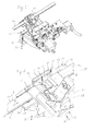
- the cutting device 20 includes a guide means 21 for receiving the tape 4a.
- the tape 4 a is withdrawn from a serving as a supply roll and inserted into the guide device 21.
- the guide device 21 removably receives the band 4a in its longitudinal direction 13 and guides it through two guide surfaces 22, 23.
- the guide surface 22 is a flat bearing surface.
- the guide surface 22 defines by its flat surface a guide plane 24 which is parallel to the longitudinal direction 13.
- the band 4a is guided by the guide surface 22 with its outer side 6 on which adheres the film serving as a vapor barrier.
- the guide surface 22 may consist of a plurality of planar or curved guide surfaces, for example rods or guide rollers which guide the belt 4a with its peripheral surfaces, so that there is only a line contact between the belt 4a and the guide surfaces 22.
- a guide plane is formed, which corresponds to the guide plane 24 in the in FIG. 2 illustrated embodiment lies.
- the guide surface 23 is at right angles to the guide surface 22 and guides the belt 4a at one of its flanks 7.
- the guide surfaces 22, 23 form the reference surfaces for precise positioning of the belt 4a during cutting.
- the band After inserting the band 4a in the guide device 21, the band is provided on its side facing away from the outside 6 inside 5 at a designated for forming a corner of the frame-shaped spacer 4 position with a notch 14, see also FIGS. 1 and 6 ,
- the cutting device 20 has for this purpose a notching tool 25, which is displaceable in a lying at right angles to the longitudinal direction 13 displacement direction 26.
- the notches 14 are incorporated into the belt 4a in such a way that the distances between two notches 14 correspond to the edge lengths of the glass panels 2, 3 of the insulating glass model pane 1 except for a small knockdown.
- a length of the band 4 adapted to the circumference of the insulating glass pane 1 is cut off from the stock of the band 4a with the aid of a displaceable separating tool 27.
- the length cut off from the supply of the band 4 a corresponds to the circumference of the frame-shaped spacer 4.
- the notched and cut to the necessary length tape along the edge of the glass sheet 2 is applied to this, in such a way that the notches 14 are each arranged in the region of a corner 9, 10 of the glass sheet 2 and that the band 4a in the Notches 14 is angled in accordance with the corner angle of the glass sheet 2.
- the band 4 is glued with a flank 7 on the first glass sheet 2, so that the notches 14 are perpendicular to the glass sheet 2.
- the beginning 17 and the end 18 of the belt 4a abut each other.
- As in FIG. 1 can be cut at the beginning 17 and end 18 of the band 4 a respectively corresponding to the half inner angle 16 of the corner 15. This ensures that the film located on the outside 6 extends both at the beginning 17 and at the end 18 to the corner 15. This ensures a good vapor-tightness of the insulating glass pane. 1
- the second glass sheet 3 After applying the spacer 4 on the first glass sheet 2, the second glass sheet 3 is glued and pressed onto the second edge 7 of the spacer 4, so that the two glass sheets 2, 3 parallel to each other in a distance defined by the width of the spacer 4 the adhesive effect of the spacer 4 are connected together to form a semi-finished insulating glass model disk 1.
- an edge joint 18, through the two glass sheets 2, 3 and the outer side 6 of the spacer. 4 is limited.
- the edge joint 18 is filled with a hardening sealing material, which produces a permanently strong composite of the glass sheets 2, 3.
- a sealing compound a polysulfite, a silicone resin or a polyurethane is well suited.
- Cutting device 20 shown is numerically controlled by a computing unit, not shown, which controls all their functions, in particular the Ausklinkwerkmaschines 25 and the cutting tool 27.
- the cutting device 20 has a displaceable separating tool 27 which has two cutters 28, 29 ( FIG. 10 ).
- the blades 28, 29 are arranged on a blade 30, which is exchangeably attached to the cutting tool 27, for example via a screw, not shown.
- the cutting device 20 includes a displacement device 31 for the cutting tool 27, with which the cutting edges 28, 29 is displaceable in a plane parallel to the displacement direction 26 of the Ausklinkwerkmaschines 25 separating plane.
- the direction of displacement 32 of the separating tool 27 runs in a straight line and at right angles to the direction of displacement 26 of the release tool 25, wherein the guide plane 24 is cut by the parting plane.
- Each of the blades 28 and 29 is straight. Both blades 28, 29 are coplanar and arranged at an angle to each other so that they form a common tip 33.
- the cutting edges 28, 29 and the tip 33 lie in said separating plane, which is oriented parallel to the displacement direction 26 of the Ausklinkmaschinemaschines 25 and parallel to the direction of displacement 32 of the separating tool 27.
- the parting plane thus corresponds to the plane of the blade 30 and is at right angles to the guide plane 24 (FIG. Fig. 9 ).
- two blades 30a, 30b may be mounted replaceably on the cutting tool 27.
- the cutting edge 28 is arranged on the knife 30a and the cutting edge 29 on the knife 30b.
- Both blades 30a, 30b are arranged back to back, so that the two blades 28, 29 in turn form a common tip 33.
- a knife can be used which has only one cutting edge 28 and extends over the entire width of the belt 4a.
- FIG. 9 the arrangement of the separating tool 27 and the displacement device 31 in relation to the guide device 21 can be seen.
- the cutting tool 27 and the displacement device 31 are located on a side facing away from the guide surface 22 of the guide device 21.
- the belt 4a lies with its outer side 6, on which the film adheres to the guide surface 22.
- the cutting 28, 29 of the cutting tool 27 can thus the displacement device 31 are moved from the outside 6 of the band 4a through the band 4a.
- the guide device 21 is provided with a gap 34 through which the blades 28, 29 can be moved.
- Each of the cutting edges 28, 29 is oriented obliquely to the guide plane 24.
- FIG. 6 The knife 30 moving through the belt 4a with the tip 33 and the blades 28, 29 is in FIG. 6 shown. From the representation of FIG. 6 It will be seen that each of the blades 28, 29 is moved through the film in a direction such that the force exerted by the blade 28, 29 on the film is oblique from the outside 6 of the belt 4a to the outside 6 in the direction of its inside 5 and each of the blades 28, 29 produces a cut which advances on the outside 6 at right angles to the longitudinal direction 13 of the belt 4a.
- the tip 33 is moved through the film starting from a location in the middle region of the outer side 6.
- the forces exerted by the two cutting edges 28, 29 on the film are obliquely directed towards the outside 6 and produce cuts which proceed on the outside 6 at right angles to the longitudinal direction 13 of the band 4a in directions opposite to each other.
- This has the advantage that the forces occurring when cutting off the film transversely to the longitudinal direction 13 substantially compensate.
- any burr arising on the film is directed towards the inside 5 of the belt 4 a so that it does not interfere with the removal of the belt 4 a from the cutting device 20.
- the two cutting edges 28, 29 are arranged wedge-shaped relative to each other, so that the common tip 33 is directed in a starting position before the cutting of the belt 4a against the guide plane 24.
- the parting plane is arranged obliquely to the guide plane 24.
- the displacement direction 32 of the separating tool 27 remains perpendicular to the direction 26 of the Ausklinktechnikmaschines 25 oriented, but then may have a deviating from 90 ° angle to the longitudinal direction 13 of the belt 4a.
- the parting plane may, for example, have such an angle to the longitudinal direction 13 that the parting plane is coplanar with one of the cut surfaces of the wedge-shaped notch 14.
- FIGS. 2 to 8 Process steps that are performed during the processing of the belt 4a by means of the cutting device 20.
- FIG. 2 the cutting device 20 is shown in the idle state. Notching tool 25 and cutting tool 27 are in their respective home position.
- the band 4 a is inserted into the guide device 21.
- the band 4a is displaced in the longitudinal direction 13 in such a way that a location provided for forming a corner of the frame-shaped spacer 4 is located in the cutting region of the release tool 25.
- the cutting device 20 has hold-downs 35, which are associated with the guide surface 22.
- the hold-down devices 35 are movable by drive devices, not shown, in the direction of the guide surface 22 and can clamp the belt 4a on the guide surface 22.
- each hold-down device 35 has a clamping surface facing the guide surface 22, which can be fed to the inside 5 of the belt 4a.
- the cutting device 20 is connected to a numerical computing unit, not shown.
- Drive means are provided, for example pneumatic cylinders and servomotors, for moving the components of the cutting device 20 in the manner described.
- the Ausklinkwerkmaschine 25 has two cutting edges 36, 37 which are arranged when viewed in its direction 26 V-shaped to each other.
- the cutting edges 36, 37 are moved in the direction of displacement 26 through the belt 4a.
- the state in which the blades 36, 37 are in the belt 4a is in FIG FIG. 3 shown.
- the cutting edges 36, 37 have a wedge-shaped piece 38 punched out of the band 4a, which is still between the two cutting edges 36, 37.
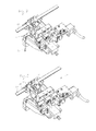
- the release tool 25 is pushed back along the direction 26 in its normal position, see illustration of FIG. 4 ,
- the punched piece 38 remains between the cutting edges 36, 37 are and then disposed of.
- the band 4a is now provided with a wedge-shaped notch 14.
- the angle between the V-shaped arranged cutting edges 36, 37 is selected so that it at least substantially complements the value of the inner angle 11, 12, 16 of the corner 9, 10, 15 of the manufactured insulating glass model pane 1 to 180 °.
- the cutting edges 36, 37 can be adjusted accordingly in a setting step before notching by the arithmetic unit, not shown.
- the notching tool 25 in the figures only schematically indicated means 39 for changing the notch angle.
- the means 39 comprises, for example, an actuator and a gear for converting a movement of the actuator in each case a pivoting movement of the two blades with the cutting edges 36 and 37.
- An advantageous embodiment of the means 39 for changing the notch is shown in FIG EP 1 839 789 B1 known.
- the V-shaped arranged cutting 36, 37 are arranged so that the tip is located at a small distance above the guide plane 24 when the notching tool 25 is displaced in the direction 26.
- the band 4a is thus not severed by the cutting edges 36, 37. Rather, the arranged on the outside 6 of the belt 4a film remains undamaged. It is advantageous to disengage the band 4a as close as possible to the film, so that as little as possible of the plastic material of the band 4a has to be folded over during the formation of the corner of the spacer 4.
- the hold-downs 35 can be lifted off the guide surface 22, so that the band 4a is no longer clamped.
- the band 4a can be pushed further in the longitudinal direction 13.
- the process of notching can be repeated at the next location of the belt 4a, at which the next corner of the spacer 4 is to be formed. The process is repeated according to the number of corners of the insulating glass pane 1.
- the hold-downs 35 are not initially opened and the band 4a remains clamped.
- the band 4a is now cut off with the cutting tool 27 in the middle of the notch 14.
- the cutting tool 27 is moved with its cutting 28, 29 of the guide surface 22 applied side of the guide plane 24 through the belt 4a therethrough.
- the gap 34 of the guide device 21 can be seen, through which the blade 30 moves therethrough.
- the band 4a is shown in the moment in which it was cut off from its outer side 6, whereby forces directed obliquely in the direction of the inside 5 of the band 4a were exerted by the cutting edges 28, 29 and the cuts were made on the outside 6 of the band 4a have spread at right angles to its longitudinal direction 13 in opposite directions.
- the separating tool 27 becomes, as in FIG. 7 shown moved back to its basic position. Subsequently, the hold-down device 35 are moved from its clamping position to its normal position, see FIG. 8 , And the cut end 18 of the belt 4a is withdrawn in the longitudinal direction 13 of the guide means 21 and fed in a manner not shown the first glass sheet 2 and glued with its edge 7 thereon.
Landscapes
- Engineering & Computer Science (AREA)
- Civil Engineering (AREA)
- Structural Engineering (AREA)
- Securing Of Glass Panes Or The Like (AREA)
- Re-Forming, After-Treatment, Cutting And Transporting Of Glass Products (AREA)
Abstract
Description
Die Erfindung betrifft ein Verfahren zur Bearbeitung eines Bandes aus Kunststoff im Verlauf der Herstellung eines rahmenförmigen Abstandhalters für eine Isolierglasscheibe gemäß dem Oberbegriff von Patentanspruch 1 und eine Schneidvorrichtung zum Durchführen des Verfahrens gemäß Oberbegriff des Patentanspruchs 6.The invention relates to a method for processing a strip of plastic in the course of producing a frame-shaped spacer for an insulating glass pane according to the preamble of patent claim 1 and a cutting device for carrying out the method according to the preamble of
Aus der
Auf der Außenseite des Abstandhalters, die durch eine Außenseite des Bandes gebildet wird, ist eine Folie angebracht, die als Dampfsperre wirkt. Die Folie besteht aus sehr wasserdampfundurchlässigen Kunststoffen und kann eine oder mehrere Lagen enthalten. Die als Dampfsperre dienende Folie verhindert, dass Luftfeuchtigkeit aus der Umgebungsluft in die Isolierglasscheibe eindringt. Dazu ist es erforderlich, dass die Folie über einen sehr langen Zeitraum von über 10 Jahren keinen Wasserdampf durchlässt, damit die in einem Gebäude eingesetzte Isolierglasscheibe möglichst über ihre gesamte Lebensdauer nicht von innen beschlägt.On the outside of the spacer, which is formed by an outside of the band, a film is attached, which acts as a vapor barrier. The film consists of very water vapor impermeable plastics and may contain one or more layers. The foil, which acts as a vapor barrier, prevents air moisture from the ambient air from penetrating into the insulating glass pane. For this purpose, it is necessary that the film does not transmit water vapor over a very long period of more than 10 years, so that the insulating glass pane used in a building does not steam up from the inside as far as possible over its entire service life.
An den Ecken einer rechteckigen Isolierglasscheibe soll das Band nach Möglichkeit rechtwinklig abgeknickt sein. Um das zu ermöglichen, wird in der
Bei Isolierglasscheiben, welche eine oder mehrere spitzwinklige und/oder stumpfwinklige Ecken haben, so genannte Modellscheiben, wird das Band mit einer keilförmigen Ausklinkung versehen, deren Keilwinkel von 90° abweicht und dem Eckenwinkel der Modellscheibe entspricht. Dadurch liegen die Schnittflächen der Ausklinkung nach dem Bilden der Ecke wiederum aneinander an.In the case of insulating glass panes which have one or more acute-angled and / or obtuse-angled corners, so-called model panes, the strip is provided with a wedge-shaped notch whose wedge angle deviates from 90 ° and corresponds to the corner angle of the model pane. As a result, the cut surfaces of the notch are again adjacent to each other after forming the corner.
Die Schneidvorrichtung der
Nach dem Ausstanzen der Ausklinkungen für die Eckenbereiche der Isolierglasscheibe wird das Band mit einem verschiebbaren Trennwerkzeug, welches in der
Das Trennwerkzeug muss beim Schneiden des Bandes auf Länge zusätzlich auch die auf der Außenseite des Bandes haftende Folie durchtrennen. Es hat sich gezeigt, dass das bekannte Trennwerkzeug zum Trennen der bekannten Bänder mit den bekannten ein- oder mehrlagigen Kunststofffolien gut geeignet ist.The cutting tool must also cut the adhesive on the outside of the tape when cutting the tape to length additionally foil. It has been found that the known separating tool for separating the known tapes with the known single or multilayer plastic films is well suited.
Eine noch weiter verbesserte Dampfdichtigkeit von Isolierglasscheiben lässt sich mit einem Abstandhalterband erreichen, welches auf seiner Außenseite mit einer Metallfolie, insbesondere aus einem nichtrostenden Edelstahl, versehen ist. Durch die Metallfolie als Dampfsperre lässt sich eine sehr hohe Dampfdichtigkeit über einen sehr langen Zeitraum erreichen.A still further improved vapor-tightness of insulating glass panes can be achieved with a spacer strip, which is provided on its outside with a metal foil, in particular of a stainless steel. Due to the metal foil as a vapor barrier, a very high vapor-tightness can be achieved over a very long period of time.
Der Erfindung liegt die Aufgabe zugrunde, ein Verfahren und eine Vorrichtung zu schaffen, mit der sich Abstandhalterbänder, welche auf ihrer Außenseite mit einer Folie versehen sind, im Verlauf der Herstellung einer Isolierglasscheibe noch besser bearbeiten lassen.The invention has for its object to provide a method and an apparatus with which spacer strips, which are provided on its outside with a foil, even better edit in the course of the production of an insulating glass.
Die Aufgabe wird durch ein Verfahren gemäß Anspruch 1 und eine Schneidvorrichtung gemäß Anspruch 6 gelöst.The object is achieved by a method according to claim 1 and a cutting device according to
Erfindungsgemäß ist vorgesehen, dass das Trennwerkzeug eine oder mehrere Schneiden aufweist, die beim Abschneiden des Bandes in einer bestimmten Richtung durch die Folien bewegt werden. Dies hat den Vorteil, dass sich das erfindungsgemäße Verfahren und die Vorrichtung besonders gut zur Bearbeitung von Abstandhalterbändern eignet, auf deren Außenseite eine Metallfolie haftet.According to the invention, it is provided that the separating tool has one or more cutting edges, which are moved through the films in a specific direction when the strip is cut off. This has the advantage that the method according to the invention and the device are particularly well suited for the processing of spacer strips, on the outside of which a metal foil adheres.
Beim Abschneiden wird jede der zumindest einen Schneide in einer Richtung durch die Folie bewegt, in welcher die von der Schneide ausgeübte Schnittkraft von der Außenseite des Bandes aus schräg zur Außenseite des Bandes in Richtung seiner Innenseite gerichtet ist, so dass die Schneide einen parallel zur Außenseite fortschreitenden Schnitt erzeugt. Bei der Schneidvorrichtung ist das Trennwerkzeug mit der Verschiebeeinrichtung derart während des Abschneidens verschiebbar, dass jede der zumindest einen Schneide schräg zu der Auflageebene orientiert und die von der Schneide ausgeübte Schnittkraft von der Außenseite des Bandes aus schräg zu seiner Innenseite gerichtet ist.During cutting, each of the at least one cutting edge is moved in one direction through the film, in which the cutting force exerted by the cutting edge is directed from the outside of the strip obliquely towards the outside of the strip in the direction of its inside, so that the cutting edge is parallel to the outside progressive cutting produced. In the cutting device, the cutting tool with the displacement device is displaceable during cutting so that each of the at least one blade is oriented obliquely to the support plane and the cutting force exerted by the blade is directed from the outside of the belt obliquely to its inside.
Dies hat den Vorteil, dass ein beim Schneiden der Folie entstehender Grat zur Innenseite des Bandes gerichtet ist. Ein Grat entsteht insbesondere dann, wenn ein Band durchtrennt wird, welches auf seine Außenseite eine als Dampfsperre dienende Metallfolie aufweist. Durch die definierte Bewegung der Schneide wird verhindert, dass an dem Band ein Grat entsteht, der zur Außenseite des Bandes gerichtet ist, der also über die Außenkontur des Bandes vorsteht, und der das Aufbringen des Abstandhalterbandes auf die Glastafel stören kann. Ein nach außen weisender Grat kann dazu führen, dass sich das Band beim weiteren Transport in der Maschine verhakt.This has the advantage that a burr formed during cutting of the film is directed towards the inside of the strip. A burr occurs in particular when a band is cut, which has on its outer side serving as a vapor barrier metal foil. The defined movement of the cutting edge prevents the formation of a burr on the strip which is directed towards the outside of the strip, that is to say projecting beyond the outer contour of the strip, and which can interfere with the application of the spacer strip to the glass sheet. An outward-pointing burr can cause the belt to get caught in the machine during further transport.
Es ist vorteilhaft, wenn das Band gleichzeitig mit zwei Schneiden abgeschnitten wird, die winkelig zu einander angeordnet sind und eine gemeinsame Spitze bilden. Die Spitze wird ausgehend von einer im mittleren Bereich der Außenseite des Bandes gelegenen Stelle in einer solchen Richtung durch die Folie hindurch bewegt, dass die von den beiden Schneiden auf die Folie ausgeübten Kräfte von der Außenseite des Bandes aus schräg zur Außenseite des Bandes in Richtung seiner Innenseite gerichtet sind und Schnitte erzeugen, die auf der Außenseite des Bandes im rechten Winkel zu dessen Längsrichtung in zueinander entgegengesetzten Richtungen fortschreiten. Diese Ausgestaltung hat den Vorteil, dass das Band bzw. die auf dem Band angeordnete Folie mit den beiden Schneiden gleichzeitig derart geschnitten wird, dass sich die parallel zur Außenseite gerichteten Komponenten der Schnittkräfte gegenseitig ausgleichen. Hierdurch lässt sich ein besonders guter Schnitt, insbesondere bei Bändern mit Metallfolie, erreichen.It is advantageous if the tape is simultaneously cut with two cutters which are arranged at an angle to each other and form a common tip. The tip is moved through the film from a location in the middle region of the outside of the belt in such a direction that the forces exerted by the two cutting edges on the film are directed from the outside of the strip obliquely towards the outside of the strip in the direction of its inside and produce cuts which proceed on the outside of the strip at right angles to its longitudinal direction in mutually opposite directions. This embodiment has the advantage that the strip or the film arranged on the strip is simultaneously cut with the two cutting edges in such a way that the components of the cutting forces directed parallel to the outside cancel each other out. This makes it possible to achieve a particularly good cut, in particular with tapes with metal foil.
Bei einer vorteilhaften Ausgestaltung der Erfindung wird jede der zumindest einen Schneide beim Abschneiden senkrecht zur Außenseite durch die Folie bewegt. Bevorzugt kommt die Außenseite des Bandes auf der Führungsfläche der Führungseinrichtung zu liegen und jede der zumindest einen Schneide ist mittels der Verschiebeeinrichtung von der der Führungsfläche abgewandten Seite her durch die Auflageebene hindurch bewegbar. Dazu kann die Verschiebeeinrichtung einen Schwenkarm oder eine Linearführung enthalten, an der das Trennwerkzeug befestigt ist. Bevorzugt ist vorgesehen, dass die Verschieberichtung des Trennwerkzeugs im rechten Winkel zu der Verschieberichtung des Ausklinkwerkzeugs verläuft und dass jede der zumindest einen Schneide des Trennwerkzeugs schräg zur Verschieberichtung des Trennwerkzeugs verläuft. Bevorzugt hat das Trennwerkzeug zumindest zwei Schneiden, die unterschiedlich schräg zur Verschieberichtung des Trennwerkzeugs verlaufen, wobei zwei der Schneiden mit ihren Enden eine keilförmige, in Verschieberichtung des Trennwerkzeugs weisende Spitze bilden.In an advantageous embodiment of the invention, each of the at least one cutting edge is moved perpendicular to the outside through the film during cutting. Preferably, the outside of the band comes to lie on the guide surface of the guide device and each of the at least one cutting edge is movable by means of the displacement device from the side facing away from the guide surface through the support plane. For this purpose, the displacement device may include a pivoting arm or a linear guide to which the separating tool is attached. It is preferably provided that the displacement direction of the separating tool runs at right angles to the direction of displacement of the Ausklinkwerkzeugs and that each of the at least one cutting edge of the cutting tool is oblique to the displacement direction of the separating tool. Preferably, the cutting tool has at least two cutting edges, which run at different obliquely to the displacement direction of the separating tool, wherein two of the cutting edges form a wedge-shaped, pointing in the direction of displacement of the cutting tool tip.
In weiterer vorteilhafter Ausgestaltung kann vorgesehen sein, dass das Band zunächst mit einer Ausklinkung für einen Eckenbereich der Isolierglasscheibe versehen wird und anschließend in der Mitte der Ausklinkung durchtrennt wird. Das Ausklinkwerkzeug hat bei Betrachtung in seiner Verschieberichtung bevorzugt zwei V-förmig angeordnete Schneiden, um das Band keilförmig auszuklinken. Bevorzugt liegt die durch die beiden V-förmig angeordneten Schneiden gebildete Spitze in der Trennebene des Trennwerkzeugs. Hierdurch kann erreicht werden, dass die Stoßstelle des Bandes genau in einer Ecke des rahmenförmigen Abstandhalters zu liegen kommt. In weiterer vorteilhafter Ausgestaltung kann vorgesehen sein, dass das Band mit einer keilförmigen Ausklinkung versehen wird, die einen Spitzenwinkel hat, der kleiner ist als der Eckenwinkel der Isolierglasscheibe in jenem Eckenbereich, in dem Anfang und Ende des Bandes aneinander stoßen. Hierdurch entsteht an der Stoßstelle des rahmenförmigen Abstandhalters zwischen den Schnittflächen am Anfang und Ende des Bandes ein keilförmiger Spalt, der sich von der Innenseite des Abstandhalters zu seiner Außenseite hin erweitert. Auf der Innenseite des rahmenförmigen Abstandhalters berühren sich Anfang und Ende des Bandes, so dass die Ecke von innen sehr sauber aussieht. Von außen kann in den Spalt aufgrund seiner Keilform sehr gut mit einer pastösen und nachfolgend erhärtenden Versiegelungsmasse gefüllt werden.In a further advantageous embodiment, it can be provided that the band is first provided with a notch for a corner region of the insulating glass pane and then cut in the middle of the notch. When viewed in its direction of displacement, the notching tool preferably has two cutters arranged in a V-shape in order to unlatch the band in a wedge-shaped manner. Preferably, the tip formed by the two V-shaped arranged cutting edges lies in the parting plane of the cutting tool. In this way it can be achieved that the joint of the tape comes to rest exactly in a corner of the frame-shaped spacer. In a further advantageous embodiment can be provided that the tape with a wedge-shaped notch having a point angle smaller than the corner angle of the insulating glass pane in that corner region where the beginning and end of the strip abut each other. This results in a wedge-shaped gap at the junction of the frame-shaped spacer between the cut surfaces at the beginning and end of the band, which widens from the inside of the spacer to its outside. On the inside of the frame-shaped spacer touch the beginning and end of the tape, so that the corner looks very clean from the inside. From the outside, due to its wedge shape, the gap can be filled very well with a pasty and subsequently hardening sealing compound.
Weitere Vorteile und Merkmale der Erfindung ergeben sich aus den Unteransprüchen und aus der nachfolgenden Beschreibung eines Ausführungsbeispiels. Die Beschreibung, die Ansprüche und die Figuren enthalten zahlreiche Merkmale in Kombination, die der Fachmann auch einzeln betrachten und zu weiteren sinnvollen Kombinationen zusammenfassen kann.Further advantages and features of the invention will become apparent from the dependent claims and from the following description of an embodiment. The description, the claims and the figures contain numerous features in combination, which the person skilled in the art can also consider individually and summarize to other meaningful combinations.
Es zeigen:
- Figur 1
- eine Isolierglas-Modellscheibe mit einem rahmenförmigen Abstandhalter und zwei Glastafeln,
Figur 2- einen Teilbereich eines Bandes zur Bildung eines Abstandhalters und eine Schneidvorrichtung in schematischer und perspektivischer Darstellung mit einem Ausklinkwerkzeug zum Einarbeiten einer Ausklinkung für einen Eckenbereich der Isolierglasscheibe in das Band und mit einem Trennwerkzeug zum Durchtrennen des Bandes,
Figur 3- das Band und die Schneidvorrichtung aus
Figur 2 Figur 4- das Band und die
Schneidvorrichtung aus Figur 3 nach dem Ausklinken mit dem Ausklinkwerkzeug in Grundstellung, Figur 5- das Band und die
Schneidvorrichtung aus Figur 4 in Arbeitsstellung des Trennwerkzeugs, Figur 6- eine vergrößerte Darstellung der
Figur 5 im Bereich der Ausklinkung des Bandes, - Figur 7
- das Band und die
Schneidvorrichtung aus Figur 5 nach dem Trennen des Bandes mit dem Trennwerkzeug in Grundstellung, Figur 8- das Abziehen des durchtrennten Bandes aus der Schneidvorrichtung der
Figur 7 , - Figur 9
- eine Vorderansicht des Bandes und der Schneidvorrichtung der
Figur 2 in Richtung des Pfeils IX, Figur 10- eine perspektivische Darstellung des Trennwerkzeuges der
Figur 2 in Grundstellung, Figur 11- eine schematische Ansicht einer Variante des Messers des Trennwerkzeugs der
Figur 10
- FIG. 1
- an insulating glass model pane with a frame-shaped spacer and two glass panels,
- FIG. 2
- a portion of a band for forming a spacer and a cutting device in a schematic and perspective view with a notching tool for incorporating a notch for a corner region of the insulating glass in the band and with a cutting tool for cutting the tape,
- FIG. 3
- the tape and the cutting device off
FIG. 2 in working position of the release tool, - FIG. 4
- the tape and the cutting device off
FIG. 3 after notching with the notching tool in basic position, - FIG. 5
- the tape and the cutting device off
FIG. 4 in working position of the separating tool, - FIG. 6
- an enlarged view of
FIG. 5 in the area of the notch of the volume, - FIG. 7
- the tape and the cutting device off
FIG. 5 after separating the strip with the cutting tool in the basic position, - FIG. 8
- the removal of the severed band from the cutting device of
FIG. 7 . - FIG. 9
- a front view of the belt and the cutting device of
FIG. 2 in the direction of the arrow IX, - FIG. 10
- a perspective view of the separating tool of
FIG. 2 In the basic position, - FIG. 11
- a schematic view of a variant of the knife of the cutting tool of
FIG. 10 ,
Die Isolierglas-Modellscheibe 1 weist zwei Ecken 9, 10 auf deren Winkel von einem rechten Winkel abweicht. Eine der Ecken 9 weist einen stumpfen Innenwinkel 11 auf, der größer als 90° ist, und eine andere Ecke 10 weist einen spitzen Innenwinkel 12 auf, der kleiner als 90° ist.The insulating glass model pane 1 has two
Zur Herstellung der Isolierglas-Modellscheibe 1 wird eine in
In nicht dargestellter Ausgestaltung kann die Führungsfläche 22 aus mehreren ebenen oder gekrümmten Führungsflächen bestehen, beispielsweise aus Stäben oder Führungsrollen, die das Band 4a mit ihren Umfangsflächen führen, so dass zwischen dem Band 4a und den Führungsflächen 22 lediglich eine Linienberührung vorliegt. Durch die Berührungsstellen der gekrümmten Führungsflächen 22 wird eine Führungsebene gebildet, die entsprechend der Führungsebene 24 in der in
Die Führungsfläche 23 liegt im rechten Winkel zu der Führungsfläche 22 und führt das Band 4a an einer seiner Flanken 7. Die Führungsflächen 22, 23 bilden die Referenzflächen für eine präzise Positionierung des Bandes 4a beim Schneiden.The
Nach dem Einlegen des Bandes 4a in die Führungseinrichtung 21 wird das Band auf seiner der Außenseite 6 abgewandten Innenseite 5 an einer für das Bilden einer Ecke des rahmenförmigen Abstandhalters 4 vorgesehenen Stelle mit einer Ausklinkung 14 versehen, siehe auch
Die Ausklinkungen 14 werden derart in das Band 4a eingearbeitet, dass die Abstände zwischen zwei Ausklinkungen 14 bis auf einen kleinen Abschlag den Kantenlängen der Glastafeln 2, 3 der Isolierglas-Modellscheibe 1 entsprechen. Nach dem Einarbeiten der Ausklinkungen 14 wird mit Hilfe eines verschiebbaren Trennwerkzeugs 27 eine dem Umfang der Isolierglasscheibe 1 angepasste Länge des Bandes 4 von dem Vorrat des Bandes 4a abgeschnitten. Die von dem Vorrat des Bandes 4a abgeschnittene Länge entspricht dem Umfang des rahmenförmigen Abstandhalters 4.The
Anschließend wird das ausgeklinkte und auf die notwendige Länge abgeschnittene Band entlang des Randes der Glastafel 2 auf diese aufgebracht, und zwar so, dass die Ausklinkungen 14 jeweils im Bereich einer Ecke 9, 10 der Glastafel 2 angeordnet sind und dass das Band 4a im Bereich der Ausklinkungen 14 in Übereinstimmung mit dem Eckenwinkel der Glastafel 2 abgewinkelt ist. Das Band 4 wird mit einer Flanke 7 auf die erste Glastafel 2 aufgeklebt, so dass die Ausklinkungen 14 senkrecht zu der Glastafel 2 verlaufen. In der Ecke 15 der Isolierglasscheibe 1 stoßen der Anfang 17 und das Ende 18 des Bandes 4a aneinander. Wie in
Nach dem Aufbringen des Abstandhalters 4 auf die erste Glastafel 2 wird die zweite Glastafel 3 auf die zweite Flanke 7 des Abstandhalters 4 geklebt und verpresst, so dass die beiden Glastafeln 2, 3 parallel zu einander in einem durch die Breite des Abstandhalters 4 definierten Abstand durch die Klebewirkung des Abstandhalters 4 miteinander zu einer halbfertigen Isolierglas-Modellscheibe 1 verbunden sind.After applying the
Durch den bei der Abmessung des Abstandhalters 4 berücksichtigten Abschlag verbleibt am gesamten Rand der halbfertigen Isolierglas-Modellscheibe 1 eine Randfuge 18, die durch die beiden Glastafeln 2, 3 und die Außenseite 6 des Abstandhalters 4 begrenzt ist. Die Randfuge 18 wird mit einem aushärtenden Versiegelungsmaterial aufgefüllt, welches einen dauerhaft festen Verbund der Glastafeln 2, 3 herstellt. Als Versiegelungsmasse ist ein Polysulfit, ein Silikonharz oder ein Polyurethan gut geeignet.By taking into account in the dimension of the
Die in
Alternativ zu einem Messer 30 mit zwei Schneiden 28, 29 können, wie in
In
Das durch das Band 4a hindurch bewegte Messer 30 mit der Spitze 33 und den Schneiden 28, 29 ist in
In nicht dargestellter Ausgestaltung kann auch vorgesehen sein, dass die Trennebene schräg zur Führungsebene 24 angeordnet ist. Die Verschieberichtung 32 des Trennwerkzeugs 27 bleibt senkrecht zur Verschieberichtung 26 des Ausklinkwerkzeugs 25 orientiert, kann dann jedoch einen von 90° abweichenden Winkel zu der Längsrichtung 13 des Bandes 4a aufweisen. Die Trennebene kann beispielsweise einen solchen Winkel zu der Längsrichtung 13 aufweisen, dass die Trennebene koplanar zu einer der Schnittflächen der keilförmigen Ausklinkung 14 liegt.In a non-illustrated embodiment can also be provided that the parting plane is arranged obliquely to the
Im Folgenden werden mit Hilfe der
In
Das Ausklinkwerkzeug 25 hat zwei Schneiden 36, 37, die bei Betrachtung in seiner Verschieberichtung 26 V-förmig zueinander angeordnet sind. Die Schneiden 36, 37 werden in Verschieberichtung 26 durch das Band 4a hindurch bewegt. Der Zustand, in dem sich die Schneiden 36, 37 in dem Band 4a befinden, ist in
Anschließend wird das Ausklinkwerkzeug 25 entlang der Verschieberichtung 26 wieder in seine Grundstellung zurück geschoben, siehe Darstellung der
Der Winkel zwischen den V-förmig angeordneten Schneiden 36, 37 wird so gewählt, dass er den Wert des Innenwinkels 11, 12, 16 der Ecke 9, 10, 15 der herzustellenden Isolierglas-Modellscheibe 1 zumindest im Wesentlichen auf 180° ergänzt. Die Schneiden 36, 37 können in einem Einstellschritt vor dem Ausklinken von der nicht dargestellten Recheneinheit entsprechend verstellt werden. Dazu enthält das Ausklinkwerkzeug 25 in den Figuren nur schematisch angedeutete Mittel 39 zum Verändern des Ausklinkungswinkels. Das Mittel 39 umfasst zum Beispiel einen Aktor und ein Getriebe zum Umsetzen einer Bewegung des Aktors in jeweils eine Schwenkbewegung der beiden Klingen mit den Schneiden 36 und 37. Eine vorteilhafte Ausgestaltung des Mittels 39 zum Verändern des Ausklinkungswinkels ist aus der
Die V-förmig angeordneten Schneiden 36, 37 sind so angeordnet, dass deren Spitze in einem geringen Abstand oberhalb der Führungsebene 24 liegt, wenn das Ausklinkwerkzeug 25 in Verschieberichtung 26 verschoben wird. Das Band 4a wird somit von den Schneiden 36, 37 nicht durchtrennt. Vielmehr bleibt die auf der Außenseite 6 des Bandes 4a angeordnete Folie unbeschädigt. Es ist vorteilhaft, das Band 4a möglichst dicht auf die Folie auszuklinken, damit bei der Bildung der Ecke des Abstandhalters 4 möglichst wenig von dem Kunststoffmaterial des Bandes 4a umgeknickt werden muss.The V-shaped arranged cutting 36, 37 are arranged so that the tip is located at a small distance above the
Nach dem Ausstanzen der Ausklinkung 14 können die Niederhalter 35 von der Führungsfläche 22 abgehoben werden, so dass das Band 4a nicht mehr geklemmt ist. Das Band 4a kann in Längsrichtung 13 weitergeschoben werden. Anschließend kann der Vorgang des Ausklinkens an der nächsten Stelle des Bandes 4a wiederholt werden, an welcher die nächste Ecke des Abstandhalters 4 gebildet werden soll. Der Vorgang wird entsprechend der Anzahl der Ecken der Isolierglasscheibe 1 wiederholt.After punching out the
Nachdem die letzte Ausklinkung 14 ausgestanzt ist werden die Niederhalter 35 zunächst nicht geöffnet und das Band 4a bleibt geklemmt. Das Band 4a wird nun mit dem Trennwerkzeug 27 in der Mitte der Ausklinkung 14 abgeschnitten. Wie in den
Nach dem Abschneiden des Bandes 4a wird das Trennwerkzeug 27, wie in
Claims (12)
mit folgenden Schritten:
beim Abschneiden des Bandes (4a) eine Schneide (28; 29) in einer solchen Richtung durch die Folie hindurch bewegt wird, dass die von der Schneide (28; 29) auf die Folie ausgeübte Kraft von der Außenseite (6) des Bandes (4a) aus schräg zur Außenseite (6) des Bandes (4a) in Richtung seiner Innenseite (5) gerichtet ist und die Schneide (28; 29) einen Schnitt erzeugt, der auf der Außenseite (6) des Bandes (4a) im rechten Winkel zu dessen Längsrichtung (13) fortschreitet.Method for processing a strip (4a) of plastic containing a desiccant in the course of producing a frame-shaped spacer (4) for an insulating glass pane (1) which has an inner side (5), an outer side (6) and two flanks (7) which in the insulating glass pane (1) to adhere to two glass sheets (2, 3) of the insulating glass pane (1), wherein on the outside (6) of the spacer (4) forming side of the strip (4a), which hereinafter referred to as the outside (6) of the tape (4a) is adhered, a film serving as a vapor barrier adheres,
with the following steps:
when cutting the tape (4a) a cutting edge (28; 29) is moved in such a direction through the film that the force exerted by the cutting edge (28; 29) on the film from the outside (6) of the tape (4a ) is directed obliquely to the outer side (6) of the belt (4a) in the direction of its inner side (5) and the cutting edge (28; 29) produces a cut which on the outer side (6) of the belt (4a) at right angles to whose longitudinal direction (13) progresses.
mit einer Führungseinrichtung (21), welche das Band (4a) in dessen Längsrichtung (13) verschieblich aufnimmt und führt und zwei einen rechten Winkel einschließende Führungsflächen (22, 23) hat,
mit einem Ausklinkwerkzeug (25) zum Ausklinken des Bandes (4a) auf seiner Innenseite (5), welches in einer im rechten Winkel zu der Längsrichtung (13) liegenden Verschieberichtung (26) verschiebbar ist,
mit einem verschiebbaren, zumindest eine Schneide (28; 29) aufweisenden Trennwerkzeug (27) zum Abschneiden des Bandes (4a),
und mit einer Verschiebeeinrichtung (31) für das Trennwerkzeug (27), mit welcher jede der zumindest einen Schneide (28; 29) in einer parallel zu der Verschieberichtung (26) des Ausklinkwerkzeugs (25) liegenden Trennebene verschiebbar ist, wobei die Führungseinrichtung (21) eine Führungsebene (24) für die Außenseite (6) des Bandes (4a) definiert, welche sowohl parallel zu der Längsrichtung (13) als auch parallel zu der Verschieberichtung (26) des Ausklinkwerkzeugs (25) orientiert ist,
und wobei die Führungsebene (24) von der Trennebene geschnitten wird,
dadurch gekennzeichnet, dass
das Trennwerkzeug (27) von seiner Verschiebeeinrichtung (31) während des Abschneidens derart verschiebbar ist,
dass dabei jede der zumindest einen Schneide (28; 29) schräg zu der Führungsebene (24) orientiert und die von der Schneide (28; 29) auf die in der Führungsebene (24) liegende Folie auf der Außenseite (6) des Bandes (4a) ausgeübte Kraft von der Außenseite (6) des Bandes (4a) aus schräg zur Außenseite (6) des Bandes (4a) in Richtung seiner Innenseite (5) gerichtet ist.Cutting device for carrying out the method according to claim 1
guide means (21) which slidably receive and guide the band (4a) in its longitudinal direction (13) and have two guide surfaces (22, 23) enclosing a right angle,
with a notching tool (25) for unlatching the band (4a) on its inner side (5), which is displaceable in a direction of displacement (26) at right angles to the longitudinal direction (13),
with a displaceable cutting tool (27) having at least one cutting edge (28; 29) for cutting off the strip (4a),
and with a displacement device (31) for the separating tool (27) with which each of the at least one cutting edge (28; 29) is displaceable in a separating plane parallel to the displacement direction (26) of the notching tool (25), wherein the guiding device (21 ) defines a guide plane (24) for the outside (6) of the strip (4a) which is oriented both parallel to the longitudinal direction (13) and parallel to the direction of displacement (26) of the notching tool (25),
and wherein the guide plane (24) is cut by the parting plane,
characterized in that
the separating tool (27) is displaceable by its displacement device (31) during the cutting off,
in that each of the at least one cutting edge (28; 29) is oriented obliquely relative to the guide plane (24) and the film lying on the outside (6) of the strip (4a) lying on the guide plane (24) of the cutting edge (28; ) is directed from the outside (6) of the band (4a) obliquely towards the outside (6) of the band (4a) in the direction of its inside (5).
und wobei die durch die beiden V-förmig angeordneten Schneiden (36, 37) gebildete Spitze in der Trennebene des Trennwerkzeugs liegt.Cutting device according to one of claims 6 to 11, in which the notching tool (25) when viewed in its direction of displacement (26) two V-shaped mutually arranged cutting edges (36, 37) has, in order to release the band (4a) wedge-shaped,
and wherein the peak formed by the two V-shaped arranged cutting edges (36, 37) lies in the parting plane of the separating tool.
Applications Claiming Priority (1)
| Application Number | Priority Date | Filing Date | Title |
|---|---|---|---|
| DE201110053286 DE102011053286A1 (en) | 2011-09-05 | 2011-09-05 | Method and device for processing a plastic strip in the manufacture of a frame-shaped spacer for insulating glass panes |
Publications (3)
| Publication Number | Publication Date |
|---|---|
| EP2565357A2 true EP2565357A2 (en) | 2013-03-06 |
| EP2565357A3 EP2565357A3 (en) | 2015-03-11 |
| EP2565357B1 EP2565357B1 (en) | 2016-09-14 |
Family
ID=46963411
Family Applications (1)
| Application Number | Title | Priority Date | Filing Date |
|---|---|---|---|
| EP12181378.6A Active EP2565357B1 (en) | 2011-09-05 | 2012-08-22 | Method and device for processing a plastic sheet to manufacture a frame-shaped spacer for insulation glass |
Country Status (4)
| Country | Link |
|---|---|
| EP (1) | EP2565357B1 (en) |
| DE (1) | DE102011053286A1 (en) |
| ES (1) | ES2602125T3 (en) |
| PL (1) | PL2565357T3 (en) |
Cited By (1)
| Publication number | Priority date | Publication date | Assignee | Title |
|---|---|---|---|---|
| CN111438727A (en) * | 2020-04-02 | 2020-07-24 | 马鞍山市恒利达机械刀片有限公司 | Cutting tool and method suitable for plastic glasses of medical protective clothing |
Citations (1)
| Publication number | Priority date | Publication date | Assignee | Title |
|---|---|---|---|---|
| EP1839789B1 (en) | 2006-03-28 | 2010-03-31 | Bystronic Lenhardt GmbH | Separating device for notching a plastic sheet to manufacture a frame-shaped spacer for insulation glass |
Family Cites Families (3)
| Publication number | Priority date | Publication date | Assignee | Title |
|---|---|---|---|---|
| JPS63229215A (en) * | 1987-03-16 | 1988-09-26 | Shoji Uchida | Multi-contact cutter |
| DE4401667C2 (en) * | 1993-02-26 | 1996-05-02 | Ladislaus Galac | Spacer frame for an insulating washer and device for its manufacture |
| US6405498B1 (en) * | 2000-03-01 | 2002-06-18 | Harry M. Riegelman | Insulating glass spacer channel seal |
-
2011
- 2011-09-05 DE DE201110053286 patent/DE102011053286A1/en not_active Withdrawn
-
2012
- 2012-08-22 EP EP12181378.6A patent/EP2565357B1/en active Active
- 2012-08-22 PL PL12181378T patent/PL2565357T3/en unknown
- 2012-08-22 ES ES12181378.6T patent/ES2602125T3/en active Active
Patent Citations (1)
| Publication number | Priority date | Publication date | Assignee | Title |
|---|---|---|---|---|
| EP1839789B1 (en) | 2006-03-28 | 2010-03-31 | Bystronic Lenhardt GmbH | Separating device for notching a plastic sheet to manufacture a frame-shaped spacer for insulation glass |
Cited By (1)
| Publication number | Priority date | Publication date | Assignee | Title |
|---|---|---|---|---|
| CN111438727A (en) * | 2020-04-02 | 2020-07-24 | 马鞍山市恒利达机械刀片有限公司 | Cutting tool and method suitable for plastic glasses of medical protective clothing |
Also Published As
| Publication number | Publication date |
|---|---|
| EP2565357B1 (en) | 2016-09-14 |
| ES2602125T3 (en) | 2017-02-17 |
| PL2565357T3 (en) | 2017-03-31 |
| EP2565357A3 (en) | 2015-03-11 |
| DE102011053286A1 (en) | 2013-03-07 |
Similar Documents
| Publication | Publication Date | Title |
|---|---|---|
| CH542051A (en) | Composite panel and process for its manufacture | |
| EP1396298B1 (en) | Method for producing multi-layered gaskets | |
| EP3453806B2 (en) | Seal element | |
| EP1839789B1 (en) | Separating device for notching a plastic sheet to manufacture a frame-shaped spacer for insulation glass | |
| EP3404156A1 (en) | Sealing strip and method for producing sealing strip | |
| EP0546392B1 (en) | Cutting blade and apparatus therewith | |
| EP2565357B1 (en) | Method and device for processing a plastic sheet to manufacture a frame-shaped spacer for insulation glass | |
| EP3318378A1 (en) | Method for coating uneven surfaces, device and component | |
| EP1652662A1 (en) | Method and apparatus for producing formatted light building panels | |
| EP3757306A1 (en) | Sealing strip | |
| DE2234902A1 (en) | METHOD AND DEVICE FOR EDGE PROCESSING AND COATING ON PANEL-SHAPED WORKPIECES | |
| DE102015000495A1 (en) | Process for the production of boards and / or blocks of wood | |
| DE202018100420U1 (en) | Device for applying edge strips | |
| WO2018015162A1 (en) | Laminated-veneer-lumber product and method for producing the same | |
| DE2408319A1 (en) | Wasteless cutting of foamed plastics laminated roofing felt - cut section supported on convex surface to prevent rotary cutter jamming | |
| DE2163731C3 (en) | ||
| EP0890687B1 (en) | Method of making a roof ridge strip | |
| EP0978339B1 (en) | Device for cutting profiles for windows or doors | |
| EP1964621B1 (en) | Device and method for manufacturing profiles | |
| DE19930199B4 (en) | Separation method and device | |
| DE3439443A1 (en) | METHOD FOR SEPARATELY SAWING WORKPIECES | |
| DE19827098B4 (en) | Method and device for cutting profile bars made of plastic or light metal | |
| WO2019057658A1 (en) | Method for processing workpieces, computer program product, and workpiece processing system | |
| DE102019131889B4 (en) | Device for creating an opening in a flexible, hollow strand of material, in particular a water hole in a strand of sealing material | |
| DE2750692C2 (en) | Process for the production of slats and slat mats |
Legal Events
| Date | Code | Title | Description |
|---|---|---|---|
| PUAI | Public reference made under article 153(3) epc to a published international application that has entered the european phase |
Free format text: ORIGINAL CODE: 0009012 |
|
| AK | Designated contracting states |
Kind code of ref document: A2 Designated state(s): AL AT BE BG CH CY CZ DE DK EE ES FI FR GB GR HR HU IE IS IT LI LT LU LV MC MK MT NL NO PL PT RO RS SE SI SK SM TR |
|
| AX | Request for extension of the european patent |
Extension state: BA ME |
|
| PUAL | Search report despatched |
Free format text: ORIGINAL CODE: 0009013 |
|
| AK | Designated contracting states |
Kind code of ref document: A3 Designated state(s): AL AT BE BG CH CY CZ DE DK EE ES FI FR GB GR HR HU IE IS IT LI LT LU LV MC MK MT NL NO PL PT RO RS SE SI SK SM TR |
|
| AX | Request for extension of the european patent |
Extension state: BA ME |
|
| RIC1 | Information provided on ipc code assigned before grant |
Ipc: E06B 3/673 20060101AFI20150205BHEP |
|
| 17P | Request for examination filed |
Effective date: 20150827 |
|
| RBV | Designated contracting states (corrected) |
Designated state(s): AL AT BE BG CH CY CZ DE DK EE ES FI FR GB GR HR HU IE IS IT LI LT LU LV MC MK MT NL NO PL PT RO RS SE SI SK SM TR |
|
| GRAP | Despatch of communication of intention to grant a patent |
Free format text: ORIGINAL CODE: EPIDOSNIGR1 |
|
| INTG | Intention to grant announced |
Effective date: 20160317 |
|
| GRAS | Grant fee paid |
Free format text: ORIGINAL CODE: EPIDOSNIGR3 |
|
| GRAA | (expected) grant |
Free format text: ORIGINAL CODE: 0009210 |
|
| AK | Designated contracting states |
Kind code of ref document: B1 Designated state(s): AL AT BE BG CH CY CZ DE DK EE ES FI FR GB GR HR HU IE IS IT LI LT LU LV MC MK MT NL NO PL PT RO RS SE SI SK SM TR |
|
| REG | Reference to a national code |
Ref country code: GB Ref legal event code: FG4D Free format text: NOT ENGLISH |
|
| REG | Reference to a national code |
Ref country code: CH Ref legal event code: EP |
|
| REG | Reference to a national code |
Ref country code: IE Ref legal event code: FG4D Free format text: LANGUAGE OF EP DOCUMENT: GERMAN |
|
| REG | Reference to a national code |
Ref country code: AT Ref legal event code: REF Ref document number: 829213 Country of ref document: AT Kind code of ref document: T Effective date: 20161015 |
|
| REG | Reference to a national code |
Ref country code: DE Ref legal event code: R096 Ref document number: 502012008204 Country of ref document: DE |
|
| REG | Reference to a national code |
Ref country code: CH Ref legal event code: NV Representative=s name: BOVARD AG PATENT- UND MARKENANWAELTE, CH |
|
| REG | Reference to a national code |
Ref country code: NL Ref legal event code: FP |
|
| REG | Reference to a national code |
Ref country code: LT Ref legal event code: MG4D |
|
| PG25 | Lapsed in a contracting state [announced via postgrant information from national office to epo] |
Ref country code: LT Free format text: LAPSE BECAUSE OF FAILURE TO SUBMIT A TRANSLATION OF THE DESCRIPTION OR TO PAY THE FEE WITHIN THE PRESCRIBED TIME-LIMIT Effective date: 20160914 Ref country code: HR Free format text: LAPSE BECAUSE OF FAILURE TO SUBMIT A TRANSLATION OF THE DESCRIPTION OR TO PAY THE FEE WITHIN THE PRESCRIBED TIME-LIMIT Effective date: 20160914 Ref country code: FI Free format text: LAPSE BECAUSE OF FAILURE TO SUBMIT A TRANSLATION OF THE DESCRIPTION OR TO PAY THE FEE WITHIN THE PRESCRIBED TIME-LIMIT Effective date: 20160914 Ref country code: RS Free format text: LAPSE BECAUSE OF FAILURE TO SUBMIT A TRANSLATION OF THE DESCRIPTION OR TO PAY THE FEE WITHIN THE PRESCRIBED TIME-LIMIT Effective date: 20160914 Ref country code: NO Free format text: LAPSE BECAUSE OF FAILURE TO SUBMIT A TRANSLATION OF THE DESCRIPTION OR TO PAY THE FEE WITHIN THE PRESCRIBED TIME-LIMIT Effective date: 20161214 |
|
| REG | Reference to a national code |
Ref country code: ES Ref legal event code: FG2A Ref document number: 2602125 Country of ref document: ES Kind code of ref document: T3 Effective date: 20170217 |
|
| PG25 | Lapsed in a contracting state [announced via postgrant information from national office to epo] |
Ref country code: SE Free format text: LAPSE BECAUSE OF FAILURE TO SUBMIT A TRANSLATION OF THE DESCRIPTION OR TO PAY THE FEE WITHIN THE PRESCRIBED TIME-LIMIT Effective date: 20160914 Ref country code: GR Free format text: LAPSE BECAUSE OF FAILURE TO SUBMIT A TRANSLATION OF THE DESCRIPTION OR TO PAY THE FEE WITHIN THE PRESCRIBED TIME-LIMIT Effective date: 20161215 Ref country code: LV Free format text: LAPSE BECAUSE OF FAILURE TO SUBMIT A TRANSLATION OF THE DESCRIPTION OR TO PAY THE FEE WITHIN THE PRESCRIBED TIME-LIMIT Effective date: 20160914 |
|
| PG25 | Lapsed in a contracting state [announced via postgrant information from national office to epo] |
Ref country code: EE Free format text: LAPSE BECAUSE OF FAILURE TO SUBMIT A TRANSLATION OF THE DESCRIPTION OR TO PAY THE FEE WITHIN THE PRESCRIBED TIME-LIMIT Effective date: 20160914 Ref country code: RO Free format text: LAPSE BECAUSE OF FAILURE TO SUBMIT A TRANSLATION OF THE DESCRIPTION OR TO PAY THE FEE WITHIN THE PRESCRIBED TIME-LIMIT Effective date: 20160914 |
|
| PG25 | Lapsed in a contracting state [announced via postgrant information from national office to epo] |
Ref country code: IS Free format text: LAPSE BECAUSE OF FAILURE TO SUBMIT A TRANSLATION OF THE DESCRIPTION OR TO PAY THE FEE WITHIN THE PRESCRIBED TIME-LIMIT Effective date: 20170114 Ref country code: SM Free format text: LAPSE BECAUSE OF FAILURE TO SUBMIT A TRANSLATION OF THE DESCRIPTION OR TO PAY THE FEE WITHIN THE PRESCRIBED TIME-LIMIT Effective date: 20160914 Ref country code: SK Free format text: LAPSE BECAUSE OF FAILURE TO SUBMIT A TRANSLATION OF THE DESCRIPTION OR TO PAY THE FEE WITHIN THE PRESCRIBED TIME-LIMIT Effective date: 20160914 Ref country code: CZ Free format text: LAPSE BECAUSE OF FAILURE TO SUBMIT A TRANSLATION OF THE DESCRIPTION OR TO PAY THE FEE WITHIN THE PRESCRIBED TIME-LIMIT Effective date: 20160914 Ref country code: BG Free format text: LAPSE BECAUSE OF FAILURE TO SUBMIT A TRANSLATION OF THE DESCRIPTION OR TO PAY THE FEE WITHIN THE PRESCRIBED TIME-LIMIT Effective date: 20161214 Ref country code: PT Free format text: LAPSE BECAUSE OF FAILURE TO SUBMIT A TRANSLATION OF THE DESCRIPTION OR TO PAY THE FEE WITHIN THE PRESCRIBED TIME-LIMIT Effective date: 20170116 |
|
| REG | Reference to a national code |
Ref country code: DE Ref legal event code: R097 Ref document number: 502012008204 Country of ref document: DE |
|
| PLBE | No opposition filed within time limit |
Free format text: ORIGINAL CODE: 0009261 |
|
| STAA | Information on the status of an ep patent application or granted ep patent |
Free format text: STATUS: NO OPPOSITION FILED WITHIN TIME LIMIT |
|
| PG25 | Lapsed in a contracting state [announced via postgrant information from national office to epo] |
Ref country code: DK Free format text: LAPSE BECAUSE OF FAILURE TO SUBMIT A TRANSLATION OF THE DESCRIPTION OR TO PAY THE FEE WITHIN THE PRESCRIBED TIME-LIMIT Effective date: 20160914 |
|
| 26N | No opposition filed |
Effective date: 20170615 |
|
| REG | Reference to a national code |
Ref country code: FR Ref legal event code: PLFP Year of fee payment: 6 |
|
| PGFP | Annual fee paid to national office [announced via postgrant information from national office to epo] |
Ref country code: NL Payment date: 20170823 Year of fee payment: 6 |
|
| PGFP | Annual fee paid to national office [announced via postgrant information from national office to epo] |
Ref country code: CH Payment date: 20170830 Year of fee payment: 6 Ref country code: ES Payment date: 20170901 Year of fee payment: 6 |
|
| PG25 | Lapsed in a contracting state [announced via postgrant information from national office to epo] |
Ref country code: SI Free format text: LAPSE BECAUSE OF FAILURE TO SUBMIT A TRANSLATION OF THE DESCRIPTION OR TO PAY THE FEE WITHIN THE PRESCRIBED TIME-LIMIT Effective date: 20160914 |
|
| PGFP | Annual fee paid to national office [announced via postgrant information from national office to epo] |
Ref country code: BE Payment date: 20170823 Year of fee payment: 6 |
|
| PG25 | Lapsed in a contracting state [announced via postgrant information from national office to epo] |
Ref country code: MC Free format text: LAPSE BECAUSE OF FAILURE TO SUBMIT A TRANSLATION OF THE DESCRIPTION OR TO PAY THE FEE WITHIN THE PRESCRIBED TIME-LIMIT Effective date: 20160914 |
|
| REG | Reference to a national code |
Ref country code: IE Ref legal event code: MM4A |
|
| PG25 | Lapsed in a contracting state [announced via postgrant information from national office to epo] |
Ref country code: LU Free format text: LAPSE BECAUSE OF NON-PAYMENT OF DUE FEES Effective date: 20170822 |
|
| PG25 | Lapsed in a contracting state [announced via postgrant information from national office to epo] |
Ref country code: IE Free format text: LAPSE BECAUSE OF NON-PAYMENT OF DUE FEES Effective date: 20170822 |
|
| REG | Reference to a national code |
Ref country code: FR Ref legal event code: PLFP Year of fee payment: 7 |
|
| PG25 | Lapsed in a contracting state [announced via postgrant information from national office to epo] |
Ref country code: MT Free format text: LAPSE BECAUSE OF FAILURE TO SUBMIT A TRANSLATION OF THE DESCRIPTION OR TO PAY THE FEE WITHIN THE PRESCRIBED TIME-LIMIT Effective date: 20160914 |
|
| PG25 | Lapsed in a contracting state [announced via postgrant information from national office to epo] |
Ref country code: AL Free format text: LAPSE BECAUSE OF FAILURE TO SUBMIT A TRANSLATION OF THE DESCRIPTION OR TO PAY THE FEE WITHIN THE PRESCRIBED TIME-LIMIT Effective date: 20160914 |
|
| REG | Reference to a national code |
Ref country code: CH Ref legal event code: PL |
|
| REG | Reference to a national code |
Ref country code: NL Ref legal event code: MM Effective date: 20180901 |
|
| PG25 | Lapsed in a contracting state [announced via postgrant information from national office to epo] |
Ref country code: LI Free format text: LAPSE BECAUSE OF NON-PAYMENT OF DUE FEES Effective date: 20180831 Ref country code: CH Free format text: LAPSE BECAUSE OF NON-PAYMENT OF DUE FEES Effective date: 20180831 |
|
| REG | Reference to a national code |
Ref country code: BE Ref legal event code: MM Effective date: 20180831 |
|
| PG25 | Lapsed in a contracting state [announced via postgrant information from national office to epo] |
Ref country code: NL Free format text: LAPSE BECAUSE OF NON-PAYMENT OF DUE FEES Effective date: 20180901 Ref country code: HU Free format text: LAPSE BECAUSE OF FAILURE TO SUBMIT A TRANSLATION OF THE DESCRIPTION OR TO PAY THE FEE WITHIN THE PRESCRIBED TIME-LIMIT; INVALID AB INITIO Effective date: 20120822 |
|
| PG25 | Lapsed in a contracting state [announced via postgrant information from national office to epo] |
Ref country code: BE Free format text: LAPSE BECAUSE OF NON-PAYMENT OF DUE FEES Effective date: 20180831 |
|
| REG | Reference to a national code |
Ref country code: ES Ref legal event code: FD2A Effective date: 20190918 |
|
| PG25 | Lapsed in a contracting state [announced via postgrant information from national office to epo] |
Ref country code: CY Free format text: LAPSE BECAUSE OF NON-PAYMENT OF DUE FEES Effective date: 20160914 Ref country code: ES Free format text: LAPSE BECAUSE OF NON-PAYMENT OF DUE FEES Effective date: 20180823 |
|
| PG25 | Lapsed in a contracting state [announced via postgrant information from national office to epo] |
Ref country code: MK Free format text: LAPSE BECAUSE OF FAILURE TO SUBMIT A TRANSLATION OF THE DESCRIPTION OR TO PAY THE FEE WITHIN THE PRESCRIBED TIME-LIMIT Effective date: 20160914 |
|
| PG25 | Lapsed in a contracting state [announced via postgrant information from national office to epo] |
Ref country code: TR Free format text: LAPSE BECAUSE OF FAILURE TO SUBMIT A TRANSLATION OF THE DESCRIPTION OR TO PAY THE FEE WITHIN THE PRESCRIBED TIME-LIMIT Effective date: 20160914 |
|
| PGFP | Annual fee paid to national office [announced via postgrant information from national office to epo] |
Ref country code: PL Payment date: 20200624 Year of fee payment: 9 |
|
| PGFP | Annual fee paid to national office [announced via postgrant information from national office to epo] |
Ref country code: FR Payment date: 20200826 Year of fee payment: 9 Ref country code: GB Payment date: 20200826 Year of fee payment: 9 |
|
| GBPC | Gb: european patent ceased through non-payment of renewal fee |
Effective date: 20210822 |
|
| PG25 | Lapsed in a contracting state [announced via postgrant information from national office to epo] |
Ref country code: GB Free format text: LAPSE BECAUSE OF NON-PAYMENT OF DUE FEES Effective date: 20210822 Ref country code: FR Free format text: LAPSE BECAUSE OF NON-PAYMENT OF DUE FEES Effective date: 20210831 |
|
| PGFP | Annual fee paid to national office [announced via postgrant information from national office to epo] |
Ref country code: IT Payment date: 20230829 Year of fee payment: 12 Ref country code: AT Payment date: 20230824 Year of fee payment: 12 |
|
| PGFP | Annual fee paid to national office [announced via postgrant information from national office to epo] |
Ref country code: DE Payment date: 20230719 Year of fee payment: 12 |
|
| PG25 | Lapsed in a contracting state [announced via postgrant information from national office to epo] |
Ref country code: PL Free format text: LAPSE BECAUSE OF NON-PAYMENT OF DUE FEES Effective date: 20210822 |