EP2979322B1 - Planar antenna apparatus and method - Google Patents
Planar antenna apparatus and method Download PDFInfo
- Publication number
- EP2979322B1 EP2979322B1 EP14775175.4A EP14775175A EP2979322B1 EP 2979322 B1 EP2979322 B1 EP 2979322B1 EP 14775175 A EP14775175 A EP 14775175A EP 2979322 B1 EP2979322 B1 EP 2979322B1
- Authority
- EP
- European Patent Office
- Prior art keywords
- plane
- unit
- antenna
- radiation
- feed
- Prior art date
- Legal status (The legal status is an assumption and is not a legal conclusion. Google has not performed a legal analysis and makes no representation as to the accuracy of the status listed.)
- Active
Links
Images


Classifications
-
- H—ELECTRICITY
- H01—ELECTRIC ELEMENTS
- H01Q—ANTENNAS, i.e. RADIO AERIALS
- H01Q9/00—Electrically-short antennas having dimensions not more than twice the operating wavelength and consisting of conductive active radiating elements
- H01Q9/04—Resonant antennas
- H01Q9/0407—Substantially flat resonant element parallel to ground plane, e.g. patch antenna
- H01Q9/045—Substantially flat resonant element parallel to ground plane, e.g. patch antenna with particular feeding means
-
- H—ELECTRICITY
- H01—ELECTRIC ELEMENTS
- H01Q—ANTENNAS, i.e. RADIO AERIALS
- H01Q1/00—Details of, or arrangements associated with, antennas
- H01Q1/12—Supports; Mounting means
- H01Q1/22—Supports; Mounting means by structural association with other equipment or articles
- H01Q1/24—Supports; Mounting means by structural association with other equipment or articles with receiving set
- H01Q1/241—Supports; Mounting means by structural association with other equipment or articles with receiving set used in mobile communications, e.g. GSM
- H01Q1/242—Supports; Mounting means by structural association with other equipment or articles with receiving set used in mobile communications, e.g. GSM specially adapted for hand-held use
- H01Q1/243—Supports; Mounting means by structural association with other equipment or articles with receiving set used in mobile communications, e.g. GSM specially adapted for hand-held use with built-in antennas
-
- H—ELECTRICITY
- H01—ELECTRIC ELEMENTS
- H01Q—ANTENNAS, i.e. RADIO AERIALS
- H01Q1/00—Details of, or arrangements associated with, antennas
- H01Q1/48—Earthing means; Earth screens; Counterpoises
-
- H—ELECTRICITY
- H01—ELECTRIC ELEMENTS
- H01Q—ANTENNAS, i.e. RADIO AERIALS
- H01Q13/00—Waveguide horns or mouths; Slot antennas; Leaky-waveguide antennas; Equivalent structures causing radiation along the transmission path of a guided wave
- H01Q13/10—Resonant slot antennas
- H01Q13/106—Microstrip slot antennas
-
- H—ELECTRICITY
- H01—ELECTRIC ELEMENTS
- H01Q—ANTENNAS, i.e. RADIO AERIALS
- H01Q21/00—Antenna arrays or systems
- H01Q21/28—Combinations of substantially independent non-interacting antenna units or systems
-
- H—ELECTRICITY
- H01—ELECTRIC ELEMENTS
- H01Q—ANTENNAS, i.e. RADIO AERIALS
- H01Q5/00—Arrangements for simultaneous operation of antennas on two or more different wavebands, e.g. dual-band or multi-band arrangements
- H01Q5/30—Arrangements for providing operation on different wavebands
- H01Q5/378—Combination of fed elements with parasitic elements
-
- H—ELECTRICITY
- H01—ELECTRIC ELEMENTS
- H01Q—ANTENNAS, i.e. RADIO AERIALS
- H01Q9/00—Electrically-short antennas having dimensions not more than twice the operating wavelength and consisting of conductive active radiating elements
- H01Q9/04—Resonant antennas
- H01Q9/0407—Substantially flat resonant element parallel to ground plane, e.g. patch antenna
- H01Q9/0421—Substantially flat resonant element parallel to ground plane, e.g. patch antenna with a shorting wall or a shorting pin at one end of the element
Definitions
- AllShare TM -based data transmission between smart devices has increased.
- Bluetooth TM and/or Wireless Fidelity (Wi-Fi)-based data transmission/reception between a smart Television (TV) and a terminal has increased.
- a dedicated antenna is mounted on the terminal and on the TV
- a data reception rate is proportional to a height of an antenna mounted on a TV.
- the data reception rate increases as the height of the antenna mounted on the TV increases. Since a TV antenna is typically mounted on a rear of a TV, the TV may be thicker as the height of the antenna increases. However, due to the characteristics of TVs which are getting slimmer, there is a limit to increasing the height of the antenna for the improvement of the data reception rate. Therefore, there is a need for a way to increase the data reception rate regardless of the height of the antenna.
- the existing patch antenna can be mounted on a TV because of the antenna's flat shape.
- an antenna is mounted on the rear of a TV, and if the patch antenna is mounted on the rear of the TV, most signals radiated from the patch antenna may exist only in the rear of the TV because the patch antenna radiates signals vertically. Therefore, a receiving device situated in front of the TV may not correctly receive the signals transmitted from the TV
- a Zeroth-Order Resonator (ZOR) antenna is a typical example of the flat-type antenna.
- the ZOR antenna is free from the antenna's physical size, and can radiate signals in parallel to the antenna's metal pattern.
- the ZOR antenna may be implemented by deriving the characteristics of a Left-Handed Material (LHM) having negative permittivity and negative permeability, which do not exist naturally, by modifying the antenna structure, due to the physical constraints of the direction in which radio waves travel in a Right-Handed Material (RHM).
- LHM Left-Handed Material
- RHM Right-Handed Material
- the ZOR antenna may be constructed in, for example, the following three forms.
- a via for connecting a radiator metal pattern printed on the top face of a two-layer substrate to a ground metal pattern on the bottom face thereof is disposed to derive a parallel inductance value of an operating frequency.
- a predetermined number of radiator metal patterns existing on a top face of the two-layer substrate need to be arranged in order to make it possible to derive a serial capacitance value and a parallel inductance value, thus, a wider horizontal antenna space is needed.
- this structure uses the via for connecting a top plate of the antenna to a bottom plate thereof, causing an increase in a total volume or a form factor. Therefore, with use of the ZOR antenna in the first form, it is hard to design a slim TV
- a second form of the ZOR antenna corresponds to an antenna structure in a Three-Dimensional (3D) form, which has a plurality of faces so that the antenna may operate in multiple bands.
- bandwidth characteristics which are a drawback of the ZOR antenna, may be improved, contributing to improving antenna performance compared with that of the ZOR antenna in the first form.
- the ZOR antenna in the second form may be hardly mounted on a small wireless device, a TV or the like, since the antenna is not implemented in a normal structure, but in a 3D structure that uses faces of a rectangular parallelepiped, causing limits of a manufacturing process due to the 3D structure.
- the third form needs a wide horizontal antenna space since the ground situated on the bottom face is disposed on the top face to implement the antenna in the planar form.
- the antenna based on the third form may enable slim products due to a thin-film antenna when the thin film antenna is mounted on the products, but the thin film antenna's performance may be distorted or its efficiency may be reduced due to the influence of the metal as the antenna is in close proximity to the products.
- US-2007/229366-A1 relates to a modified inverted-F antenna for wireless communication.
- the antenna circuit includes a dielectric substrate having a first surface, a radiating stub on the first surface of the dielectric substrate, and a first ground plate on the first surface of the dielectric substrate to couple to ground.
- the first ground plate includes one or more grounded capacitive stubs spaced apart from the radiating stub.
- the one or more grounded capacitive stubs tune performance parameters for the antenna circuit.
- It is an aim of certain embodiments of the present disclosure is to provide a planar antenna apparatus and method.
- Another aim of the present disclosure is to provide a planar antenna apparatus and method in which an antenna has a planar structure, enables horizontal radiation, and can be configured to be ultra-thin.
- a planar antenna apparatus is provided according to claim 1.
- a method for transmitting a signal is provided according to claim 7.
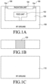
- FIGS. 1A to 1C illustrate a structure of an antenna according to an embodiment of the present disclosure.
- the top face of the antenna has a flat structure, and includes a substrate 108 of a conductive metal pattern, a Radio Frequency (RF) ground 100, a feed unit 102, a radiation unit 104, and at least one via 106.
- RF Radio Frequency
- the RF ground 100 to which a plurality of antenna elements are grounded, is connected to the radiation unit 104 through the via 106.
- the feed unit 102 may feed a current to the radiation unit 104, and apply a signal provided from an RF chip to the radiation unit 104.
- the radiation unit 104 may radiate the signal applied from the feed unit 102.
- the feed unit 102 and the radiation unit 104 may perform a signal applying operation using an inductive scheme or a capacitive coupling scheme.
- a serial capacitance value and a parallel inductance value on an equivalent circuit of the antenna are determined so that a signal is radiated horizontally.
- the serial capacitance value and the parallel inductance value are determined as values that cause a resonant frequency to be zero in a predetermined frequency band so that they have ZOR antenna characteristics.
- the determined serial capacitance value is used to determine a separation distance between the feed unit 102 and the radiation unit 104
- the determined parallel inductance value is used to determine a width and a length of the radiation unit 104.
- the RF ground 100, the feed unit 102, the radiation unit 104 and the via 106 are disposed on a top face of the antenna. In this antenna, a signal may be radiated in parallel to the substrate 108.
- the side face of the antenna includes a connection unit 109 that connects the top face of the antenna to a bottom face thereof.
- the connection unit 109 is used to implement a switching function capable of adjusting a radiation direction and/or azimuth of the antenna, and a detailed description thereof will be made later.
- the bottom face of the antenna is illustrated.
- the bottom face of the antenna is configured in a form in which an RF ground 110 is included.
- the bottom face of the antenna is configured in a form in which the RF ground 100 on the top face is extended in order to reduce the influence of the metal when the antenna is mounted on a device.
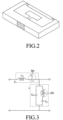
- FIG. 2 illustrates an antenna according to an embodiment of the present disclosure.
- the antenna having the structures as in FIGS. 1A to 1C may have a structure of a rectangular parallelepiped as illustrated in FIG. 2 .
- FIG. 3 illustrates an equivalent circuit included in an antenna according to an embodiment of the present disclosure.
- the equivalent circuit includes a serial capacitance C L 300 and a parallel inductance L L 320.
- a resonant frequency of the antenna is determined depending on values of the serial capacitance C L 300 and the parallel inductance L L 320. Therefore, in an embodiment of the present disclosure, the ZOR characteristics having an infinite wavelength may be implemented by adjusting the values of the serial capacitance C L 300 and the parallel inductance L L 320 so that the resonant frequency may be zero in a specific frequency band.
- the ZOR characteristics may be achieved by adjusting the separation distance between the feed unit 102 and the radiation unit 104 to determine the value of the serial capacitance C L 300 and by adjusting the width and the length of the radiation unit 104 to determine the value of the parallel inductance L L 320.
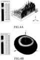
- FIGS. 4A and 4B illustrate forms in which a signal is horizontally radiated from an antenna according to an embodiment of the present disclosure.
- FIGS. 5A and 5B illustrate an antenna mounted on a TV according to an embodiment of the present disclosure.
- the antenna is assumed to be mounted on a TV in this embodiment, the antenna may be mounted on the TV and also on other devices capable of wireless communication.
- An antenna 500 according to an embodiment of the present disclosure may be mounted on the rear of a TV 502 as illustrated in FIG. 5A .
- the antenna 500 may be mounted to be spaced apart from the TV 502 by a specific separation distance as illustrated in FIG. 5B , or the antenna 500 may be mounted without the separation distance.
- a form in which a signal is radiated from the antenna 500 mounted on the TV 502 is illustrated in FIG. 6 .
- FIG. 6 illustrates a form in which a signal is radiated from an antenna mounted on a TV according to an embodiment of the present disclosure.
- a signal radiated from the antenna 500 attached to and/or mounted on the rear of the TV 502 may be transmitted to a receive antenna 504, which may also be referred to as an RX antenna 504, situated in front of the TV 502.
- the antenna 500 attached to the rear of the TV 502 may be a horizontal radiation antenna, and a comparison between the horizontal radiation antenna and the existing vertical radiation antenna is illustrated in FIGS. 7A and 7B .
- FIGS. 7A and 7B illustrate a comparison between a typical vertical radiation antenna and a horizontal radiation antenna according to an embodiment of the present disclosure.
- the horizontal radiation antenna illustrated in FIG. 7B may radiate more signals toward the front of the TV when it is mounted on the rear of the TV.
- the horizontal radiation antenna compared with the vertical radiation antenna, may have a higher antenna gain, for example, an antenna gain higher by 3 to 7 dB.
- FIG. 8 is a graph illustrating a change in operating frequency based on a distance between a TV and an antenna according to an embodiment of the present disclosure.
- a first operating frequency 800 of the antenna before the antenna is mounted on the TV may fall within a range of 2.4GHz to 2.6GHz. Therefore, in an embodiment of the present disclosure, a change in an operating frequency of the antenna may be very small, even though the antenna is mounted in close proximity to the metallic rear of the TV.
- a second radiation efficiency 902 of the antenna when the distance between the antenna and the TV is 0.1mm, and a third radiation efficiency 904 of the antenna when the distance between the antenna and the TV is 2mm may be higher.
- the related-art antenna's radiation efficiency is reduced to 20% of the normal radiation efficiency, if the antenna is in close proximity to the metal.
- the influence of the metal, which affects the antenna performance may be significantly reduced, since the RF ground is disposed on the bottom face of the antenna. As a result, the radiation efficiency may be higher as the antenna gets closer to the metal.
- connection unit 1000 for connecting an RF ground on a top face of the antenna to an RF ground on a bottom face of the antenna may be disposed on a side face of the antenna.
- the connection unit 1000 may be used to implement a switching function capable of reconfiguring the antenna pattern. A detailed description thereof will be made with reference to FIGS. 11A and 11B .
- FIGS. 11A and 11B illustrate a position of a connection unit which is changed for a switching function according to an embodiment of the present disclosure.
- the connection unit 1000 moves from a central position of the side face of the antenna towards a left direction by a preset distance, size, or length, e.g., 6mm, the pattern, e.g., radiation direction, of the antenna may be changed from an existing direction to the left direction.
- a preset distance, size, or length e.g. 6mm
- the pattern e.g., the radiation direction of the antenna may be changed from the existing direction to the right direction.
- the antenna patterns based on the changes in position of the connection unit 1000 is as illustrated in FIGS. 12A to 12C .
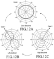
- FIGS. 12A to 12C illustrate antenna patterns based on changes in position of a connection unit according to an embodiment of the present disclosure.
- connection unit 1000 when the connection unit 1000 is situated in the exact center and/or at approximately the exact center of the side face of the antenna is illustrated.
- the radiation direction of the antenna may be omni-directional, and the antenna may have the omni-directional characteristics.
- FIG. 12B a pattern of an antenna when the position of the connection unit 1000 moves from the central position of the side face of the antenna to the left by a preset distance, size, or length, as illustrated in FIG. 11A , is illustrated.
- FIG. 12B it can be noted that if the position of the connection unit 1000 moves to the left by the preset distance, size, or length, the radiation direction of the antenna is biased to the left.
- FIG. 12C a pattern of an antenna when the position of the connection unit 1000 moves from the central position of the side face of the antenna to the right by a preset distance, size, or length, as illustrated in FIG. 11B , is illustrated.
- FIG. 12C it can be noted that if the position of the connection unit 1000 moves to the right by the preset distance, size, or length, the radiation direction of the antenna is biased to the right.
- the antenna patterns as illustrated in FIGS. 12A to 12C may be selectively used depending on the position of the connection unit 1000.
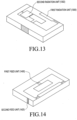
- FIG. 13 illustrates an antenna with a radiation unit additionally configured thereon according to an embodiment of the present disclosure.
- an antenna may further include at least one radiation unit.
- the antenna may include a second radiation unit 1302 as a parasitic radiation unit, in addition to a first radiation unit 1300 that has the same form as that of the radiation unit 104 illustrated in FIG. 1 .
- the second radiation unit 1302 may transmit signals using a frequency band different from that of the first radiation unit 1300. Accordingly, if the second radiation unit 1302 is additionally used, the antenna bandwidth may be extended, contributing to an increase in antenna efficiency.
- the antenna illustrated in FIG. 13 may have a same structure as that of the above-described antenna in FIG. 1 , except that the second radiation antenna 1302 is additionally included in the antenna of the embodiment of FIG. 13 .
- FIG. 14 illustrates an antenna including a plurality of feed units according to an embodiment of the present disclosure.
- an antenna may include a plurality of feed units.
- the antenna may include a first feed unit 1400 for horizontal radiation and a second feed unit 1420 for vertical radiation.
- the antenna may be configured in a form in which one feed line for the second feed unit 1420 is added to the antenna illustrated in FIG. 1 .
- the first feed unit 1400 and the second feed unit 1420 may be selectively used. In other words, one of the first feed unit 1400 and the second feed unit 1420 may be selected and used by an RF chip depending on the signal strength thereof. The selected feed unit may have the higher signal strength. If one feed unit is selected and turned on, another feed unit may be turned off, and the first feed unit 1400 and the second feed unit 1420 may be used in a switched way, or in other words may be alternatively used.
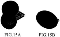
- Radiation patterns of the first feed unit 1400 and the second feed unit 1420 are as illustrated in FIGS. 15A and 15B .
- FIGS. 15A and 15B illustrate vertical radiation and horizontal radiation occurring from an antenna according to an embodiment of the present disclosure.
- FIG. 15A a case in which vertical radiation of an antenna, which occurs if the second feed unit 1420 is selected, is illustrated.
- FIG. 15B a case in which horizontal radiation of an antenna, which occurs if the first feed unit 1400 is selected, is illustrated.
- the horizontal radiation and also the vertical radiation may be achieved by adding one feed line to one antenna, thereby making it possible to increase an operation coverage, or in other words, an operational area and/or coverage area, of the antenna with the simple and small structure.
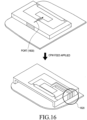
- FIG. 16 illustrates an antenna including a Coplanar Wave Guide (CPW) feed line according to an embodiment of the present disclosure.
- CPW Coplanar Wave Guide
- the planar antenna described in conjunction with FIG. 1 may be attached to a Printed Circuit Board (PCB), a metal or the like.
- PCB Printed Circuit Board
- a metal or the like the antenna efficiency and performance may be degraded.
- a CPW feed line 1620 may be used, as illustrated in FIG. 16 .
- the CPW feed line 1620 is used to perform feeding by using the PCB and/or the metal as a part of the antenna, so the CPW feed line 1620 may prevent the decrease in energy radiation efficiency, which is caused as power is applied through a port 1600.
- FIG. 17 illustrates an operating frequency of an antenna including a CPW feed line according to an embodiment of the present disclosure.
- the operating frequency of the antenna may be kept at 2.3GHz. In other words, during feeding, the horizontal radiation characteristics of the antenna may be kept constant.
- an air-bridge may be applied to the antenna.
- FIGS. 18A and 18B illustrate an antenna that uses an air-bridge according to an embodiment of the present disclosure.
- an air-bridge 1800 may be added to the CPW feed line, as illustrated in FIG. 18B . If the air-bridge 1800 is added, an even mode may occur, in which all signals on the CPW feed line have a same phase and a potential difference is eliminated. Accordingly, the antenna efficiency may increase, and a detailed description thereof will be made with reference to FIG. 19 .
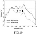
- FIG. 19 is a graph illustrating an efficiency of an antenna that uses an air-bridge according to an embodiment of the present disclosure.
- an air-bridge is used in an antenna, all directions of electric fields in a ground field may be changed to a same direction, so the efficiency may be higher compared to when the air-bridge is not used. If an air-bridge is used in the antenna in, for example, a 100MHz band, the antenna may have an efficiency which is higher by 10% on average, compared with when the air-bridge is not used.
- a plurality of antennas may be additionally used in various forms such as being configured in an array form.
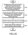
- FIG. 20 is a flowchart illustrating a process of configuring an antenna according to an embodiment of the present disclosure.
- a serial capacitance value between the radiation unit 104 and the feed unit 102 and a parallel inductance value based on a length and a width of the radiation unit 104 may be determined to have ZOR antenna characteristics.
- the radiation unit 104, the feed unit 102, the RF ground 100 and the via 106 are disposed on a top face of the planar antenna.
- the RF ground 110 may be disposed on the bottom face of the antenna.
- the connection unit 109 for connecting the two RF grounds 100 and 110, is disposed on the side face of the antenna. If the antenna is configured as described above, signals may be transmitted in a form in which the signals are horizontally radiated.
- a planar antenna proposed in the present disclosure has a planar structure, enables horizontal radiation, and may increase antenna efficiency at low cost.
- the planar antenna adjusts the horizontal radiation direction and extends an antenna bandwidth.
- the planar antenna may be configured to be ultra-thin, since the planar antenna has a volume of less than half when compared to the related-art antenna. Therefore, the planar antenna may be mounted on a variety of wireless communication devices which are getting slim, such as cellular terminals, TVs and the like.
- the antenna may increase price competitiveness and maximize mass production because the antenna can be produced at low cost.
Landscapes
- Engineering & Computer Science (AREA)
- Computer Networks & Wireless Communication (AREA)
- Details Of Aerials (AREA)
- Variable-Direction Aerials And Aerial Arrays (AREA)
- Waveguide Aerials (AREA)
- Support Of Aerials (AREA)
Applications Claiming Priority (2)
| Application Number | Priority Date | Filing Date | Title |
|---|---|---|---|
| KR20130032017 | 2013-03-26 | ||
| PCT/KR2014/002564 WO2014157947A1 (en) | 2013-03-26 | 2014-03-26 | Planar antenna apparatus and method |
Publications (3)
| Publication Number | Publication Date |
|---|---|
| EP2979322A1 EP2979322A1 (en) | 2016-02-03 |
| EP2979322A4 EP2979322A4 (en) | 2016-11-23 |
| EP2979322B1 true EP2979322B1 (en) | 2024-07-17 |
Family
ID=51620265
Family Applications (1)
| Application Number | Title | Priority Date | Filing Date |
|---|---|---|---|
| EP14775175.4A Active EP2979322B1 (en) | 2013-03-26 | 2014-03-26 | Planar antenna apparatus and method |
Country Status (6)
Families Citing this family (10)
| Publication number | Priority date | Publication date | Assignee | Title |
|---|---|---|---|---|
| CN104377449A (zh) * | 2013-08-15 | 2015-02-25 | 同方威视技术股份有限公司 | 宽带微带天线和天线阵列 |
| CN106663864B (zh) | 2014-12-22 | 2020-03-10 | 华为技术有限公司 | 一种天线和终端 |
| KR102397407B1 (ko) * | 2015-02-27 | 2022-05-13 | 삼성전자주식회사 | 안테나 장치 및 그를 구비하는 전자 장치 |
| KR102469566B1 (ko) | 2016-03-31 | 2022-11-22 | 삼성전자주식회사 | 안테나 장치를 포함하는 전자 장치 |
| US10033100B1 (en) * | 2017-10-03 | 2018-07-24 | Vayyar Imaging Ltd. | Floating dipole antenna with recess excitation |
| US11271309B2 (en) | 2018-08-10 | 2022-03-08 | Ball Aerospace & Technologies Corp. | Systems and methods for interconnecting and isolating antenna system components |
| USD916688S1 (en) * | 2018-09-24 | 2021-04-20 | Galvani Bioelectronics Limited | Planar antenna |
| WO2021085688A1 (ko) * | 2019-11-01 | 2021-05-06 | 엘지전자 주식회사 | 디스플레이 내장 안테나를 구비하는 전자 기기 |
| JP7298517B2 (ja) * | 2020-03-05 | 2023-06-27 | 株式会社デンソー | 電子装置 |
| CN113839204B (zh) * | 2021-09-18 | 2023-01-31 | 荣耀终端有限公司 | 移动终端及高隔离天线对 |
Family Cites Families (27)
| Publication number | Priority date | Publication date | Assignee | Title |
|---|---|---|---|---|
| US4291311A (en) | 1977-09-28 | 1981-09-22 | The United States Of America As Represented By The Secretary Of The Navy | Dual ground plane microstrip antennas |
| JP3178764B2 (ja) | 1994-02-21 | 2001-06-25 | 日本電信電話株式会社 | スロットアンテナの給電回路 |
| US5696517A (en) * | 1995-09-28 | 1997-12-09 | Murata Manufacturing Co., Ltd. | Surface mounting antenna and communication apparatus using the same |
| US5748149A (en) * | 1995-10-04 | 1998-05-05 | Murata Manufacturing Co., Ltd. | Surface mounting antenna and antenna apparatus |
| JP3319268B2 (ja) | 1996-02-13 | 2002-08-26 | 株式会社村田製作所 | 表面実装型アンテナおよびこれを用いた通信機 |
| JP3279205B2 (ja) * | 1996-12-10 | 2002-04-30 | 株式会社村田製作所 | 表面実装型アンテナおよび通信機 |
| DE60115131T2 (de) * | 2000-04-14 | 2006-08-17 | Hitachi Metals, Ltd. | Chip-Antennenelement und dieses aufweisendes Nachrichtenübertragungsgerät |
| JP4409257B2 (ja) | 2003-11-18 | 2010-02-03 | シャープ株式会社 | 無線タグ及びそれを備えた物品並びにrfidシステム |
| US7330090B2 (en) * | 2004-03-26 | 2008-02-12 | The Regents Of The University Of California | Zeroeth-order resonator |
| US7245268B2 (en) * | 2004-07-28 | 2007-07-17 | Skycross, Inc. | Quadrifilar helical antenna |
| CN101111972B (zh) * | 2005-01-27 | 2015-03-11 | 株式会社村田制作所 | 天线及无线通信设备 |
| WO2007035064A1 (en) * | 2005-09-23 | 2007-03-29 | Ace Antenna Corp. | Chip antenna |
| US7450072B2 (en) * | 2006-03-28 | 2008-11-11 | Qualcomm Incorporated | Modified inverted-F antenna for wireless communication |
| JP2007325118A (ja) | 2006-06-02 | 2007-12-13 | Toyota Motor Corp | アンテナ装置 |
| CN101542838B (zh) | 2006-08-25 | 2013-03-13 | 泰科电子服务有限责任公司 | 基于超材料结构的天线 |
| JP2008054146A (ja) | 2006-08-26 | 2008-03-06 | Toyota Central R&D Labs Inc | アレーアンテナ |
| US7952526B2 (en) | 2006-08-30 | 2011-05-31 | The Regents Of The University Of California | Compact dual-band resonator using anisotropic metamaterial |
| FI119404B (fi) | 2006-11-15 | 2008-10-31 | Pulse Finland Oy | Sisäinen monikaista-antenni |
| KR20080112502A (ko) * | 2007-06-21 | 2008-12-26 | (주)케이티에프테크놀로지스 | 다중대역 안테나 및 이를 구비한 휴대 단말기 |
| KR100901819B1 (ko) | 2007-08-10 | 2009-06-09 | 한양대학교 산학협력단 | 회로기판 일체형 안테나 |
| TWI383539B (zh) * | 2009-08-14 | 2013-01-21 | Univ Nat Chiao Tung | 共平面天線單元及共平面天線 |
| KR20110025047A (ko) * | 2009-09-01 | 2011-03-09 | 중앙대학교 산학협력단 | 향상된 대역폭 및 높은 효율을 가지며 구현이 간단한 소형 0차 공진 안테나 |
| CN102696149B (zh) * | 2009-11-13 | 2014-09-03 | 日立金属株式会社 | 变频天线电路、构成它的天线部件、以及使用了它们的无线通信装置 |
| US8604998B2 (en) * | 2010-02-11 | 2013-12-10 | Radina Co., Ltd | Ground radiation antenna |
| US9246221B2 (en) | 2011-03-07 | 2016-01-26 | Apple Inc. | Tunable loop antennas |
| JP5901130B2 (ja) * | 2011-03-29 | 2016-04-06 | 富士通コンポーネント株式会社 | アンテナ装置、回路基板及びメモリカード |
| CN202513285U (zh) | 2012-01-18 | 2012-10-31 | 华南理工大学 | 一种加载零阶谐振器的多极化微带贴片天线 |
-
2014
- 2014-03-26 EP EP14775175.4A patent/EP2979322B1/en active Active
- 2014-03-26 US US14/225,779 patent/US10074905B2/en not_active Expired - Fee Related
- 2014-03-26 CN CN201480017883.5A patent/CN105075007B/zh not_active Expired - Fee Related
- 2014-03-26 WO PCT/KR2014/002564 patent/WO2014157947A1/en active Application Filing
- 2014-03-26 JP JP2016505397A patent/JP6386025B2/ja not_active Expired - Fee Related
- 2014-03-26 KR KR1020140035191A patent/KR102060331B1/ko not_active Expired - Fee Related
Non-Patent Citations (1)
| Title |
|---|
| CHIEN-PAI LAI ET AL: "Zeroth-Order Resonator Antennas Using Inductor-Loaded and Capacitor-Loaded CPWs", IEEE TRANSACTIONS ON ANTENNAS AND PROPAGATION, IEEE SERVICE CENTER, PISCATAWAY, NJ, US, vol. 59, no. 9, 1 September 2011 (2011-09-01), pages 3448 - 3453, XP011359257, ISSN: 0018-926X, DOI: 10.1109/TAP.2011.2161561 * |
Also Published As
| Publication number | Publication date |
|---|---|
| CN105075007B (zh) | 2018-09-11 |
| CN105075007A (zh) | 2015-11-18 |
| KR20140117309A (ko) | 2014-10-07 |
| US20140292601A1 (en) | 2014-10-02 |
| JP6386025B2 (ja) | 2018-09-05 |
| WO2014157947A1 (en) | 2014-10-02 |
| EP2979322A4 (en) | 2016-11-23 |
| JP2016518044A (ja) | 2016-06-20 |
| KR102060331B1 (ko) | 2019-12-31 |
| US10074905B2 (en) | 2018-09-11 |
| EP2979322A1 (en) | 2016-02-03 |
Similar Documents
| Publication | Publication Date | Title |
|---|---|---|
| EP2979322B1 (en) | Planar antenna apparatus and method | |
| EP3469656B1 (en) | An antenna system for a portable device | |
| JP6374971B2 (ja) | アンテナユニット及び端末 | |
| US11923626B2 (en) | Antenna apparatus and mobile terminal | |
| CN104253303B (zh) | 多天线系统和移动终端 | |
| WO2012088837A1 (zh) | 一种移动终端的阵列天线及其实现方法 | |
| CN114447583B (zh) | 天线及电子设备 | |
| US20100149048A1 (en) | Dual-band antenna and portable wireless communication device employing the same | |
| CN110970709B (zh) | 天线结构及具有该天线结构的无线通信装置 | |
| CN101431179A (zh) | 具有延伸接地面的平面倒f天线 | |
| CN106571523A (zh) | 一种终端多输入多输出高隔离可调天线 | |
| CN210272672U (zh) | 天线以及电子设备 | |
| CN105789855A (zh) | 一种新型的双频带ebg结构 | |
| US11342669B2 (en) | Antenna structure and wireless communication device using same | |
| US20140232608A1 (en) | Antenna Apparatus and a Method | |
| CN107026313B (zh) | 用于无线通信模块的天线 | |
| CN108879112A (zh) | 天线阵列及终端 | |
| WO2019227651A1 (zh) | 便携式通信终端及其pifa天线 | |
| US9627747B2 (en) | Dual-polarized magnetic antennas | |
| US9059500B2 (en) | Capacitive loop antenna and electronic device | |
| CN102157794B (zh) | 谐振产生的三频段天线 | |
| TWI683474B (zh) | 立體式天線元件 | |
| US20130082894A1 (en) | Integrated antenna and method for operating integrated antenna device | |
| CN104885297A (zh) | 多频带天线和无线装置 |
Legal Events
| Date | Code | Title | Description |
|---|---|---|---|
| PUAI | Public reference made under article 153(3) epc to a published international application that has entered the european phase |
Free format text: ORIGINAL CODE: 0009012 |
|
| 17P | Request for examination filed |
Effective date: 20150608 |
|
| AK | Designated contracting states |
Kind code of ref document: A1 Designated state(s): AL AT BE BG CH CY CZ DE DK EE ES FI FR GB GR HR HU IE IS IT LI LT LU LV MC MK MT NL NO PL PT RO RS SE SI SK SM TR |
|
| AX | Request for extension of the european patent |
Extension state: BA ME |
|
| DAX | Request for extension of the european patent (deleted) | ||
| A4 | Supplementary search report drawn up and despatched |
Effective date: 20161024 |
|
| RIC1 | Information provided on ipc code assigned before grant |
Ipc: H01Q 5/378 20150101ALI20161018BHEP Ipc: H01Q 1/48 20060101ALI20161018BHEP Ipc: H01Q 1/46 20060101ALI20161018BHEP Ipc: H01Q 1/24 20060101AFI20161018BHEP Ipc: H01Q 21/28 20060101ALI20161018BHEP Ipc: H01Q 13/10 20060101ALI20161018BHEP Ipc: H01Q 9/04 20060101ALI20161018BHEP |
|
| STAA | Information on the status of an ep patent application or granted ep patent |
Free format text: STATUS: EXAMINATION IS IN PROGRESS |
|
| 17Q | First examination report despatched |
Effective date: 20200903 |
|
| STAA | Information on the status of an ep patent application or granted ep patent |
Free format text: STATUS: EXAMINATION IS IN PROGRESS |
|
| GRAP | Despatch of communication of intention to grant a patent |
Free format text: ORIGINAL CODE: EPIDOSNIGR1 |
|
| STAA | Information on the status of an ep patent application or granted ep patent |
Free format text: STATUS: GRANT OF PATENT IS INTENDED |
|
| INTG | Intention to grant announced |
Effective date: 20231218 |
|
| GRAJ | Information related to disapproval of communication of intention to grant by the applicant or resumption of examination proceedings by the epo deleted |
Free format text: ORIGINAL CODE: EPIDOSDIGR1 |
|
| STAA | Information on the status of an ep patent application or granted ep patent |
Free format text: STATUS: EXAMINATION IS IN PROGRESS |
|
| GRAP | Despatch of communication of intention to grant a patent |
Free format text: ORIGINAL CODE: EPIDOSNIGR1 |
|
| STAA | Information on the status of an ep patent application or granted ep patent |
Free format text: STATUS: GRANT OF PATENT IS INTENDED |
|
| INTC | Intention to grant announced (deleted) | ||
| INTG | Intention to grant announced |
Effective date: 20240508 |
|
| GRAS | Grant fee paid |
Free format text: ORIGINAL CODE: EPIDOSNIGR3 |
|
| GRAA | (expected) grant |
Free format text: ORIGINAL CODE: 0009210 |
|
| STAA | Information on the status of an ep patent application or granted ep patent |
Free format text: STATUS: THE PATENT HAS BEEN GRANTED |
|
| AK | Designated contracting states |
Kind code of ref document: B1 Designated state(s): AL AT BE BG CH CY CZ DE DK EE ES FI FR GB GR HR HU IE IS IT LI LT LU LV MC MK MT NL NO PL PT RO RS SE SI SK SM TR |
|
| REG | Reference to a national code |
Ref country code: GB Ref legal event code: FG4D |
|
| REG | Reference to a national code |
Ref country code: CH Ref legal event code: EP |
|
| REG | Reference to a national code |
Ref country code: DE Ref legal event code: R096 Ref document number: 602014090521 Country of ref document: DE |
|
| REG | Reference to a national code |
Ref country code: IE Ref legal event code: FG4D |
|
| REG | Reference to a national code |
Ref country code: LT Ref legal event code: MG9D |
|
| REG | Reference to a national code |
Ref country code: NL Ref legal event code: MP Effective date: 20240717 |
|
| PG25 | Lapsed in a contracting state [announced via postgrant information from national office to epo] |
Ref country code: PT Free format text: LAPSE BECAUSE OF FAILURE TO SUBMIT A TRANSLATION OF THE DESCRIPTION OR TO PAY THE FEE WITHIN THE PRESCRIBED TIME-LIMIT Effective date: 20241118 |
|
| REG | Reference to a national code |
Ref country code: AT Ref legal event code: MK05 Ref document number: 1705020 Country of ref document: AT Kind code of ref document: T Effective date: 20240717 |
|
| PG25 | Lapsed in a contracting state [announced via postgrant information from national office to epo] |
Ref country code: NL Free format text: LAPSE BECAUSE OF FAILURE TO SUBMIT A TRANSLATION OF THE DESCRIPTION OR TO PAY THE FEE WITHIN THE PRESCRIBED TIME-LIMIT Effective date: 20240717 |
|
| PG25 | Lapsed in a contracting state [announced via postgrant information from national office to epo] |
Ref country code: PT Free format text: LAPSE BECAUSE OF FAILURE TO SUBMIT A TRANSLATION OF THE DESCRIPTION OR TO PAY THE FEE WITHIN THE PRESCRIBED TIME-LIMIT Effective date: 20241118 Ref country code: NL Free format text: LAPSE BECAUSE OF FAILURE TO SUBMIT A TRANSLATION OF THE DESCRIPTION OR TO PAY THE FEE WITHIN THE PRESCRIBED TIME-LIMIT Effective date: 20240717 |
|
| PG25 | Lapsed in a contracting state [announced via postgrant information from national office to epo] |
Ref country code: NO Free format text: LAPSE BECAUSE OF FAILURE TO SUBMIT A TRANSLATION OF THE DESCRIPTION OR TO PAY THE FEE WITHIN THE PRESCRIBED TIME-LIMIT Effective date: 20241017 |
|
| PG25 | Lapsed in a contracting state [announced via postgrant information from national office to epo] |
Ref country code: FI Free format text: LAPSE BECAUSE OF FAILURE TO SUBMIT A TRANSLATION OF THE DESCRIPTION OR TO PAY THE FEE WITHIN THE PRESCRIBED TIME-LIMIT Effective date: 20240717 Ref country code: PL Free format text: LAPSE BECAUSE OF FAILURE TO SUBMIT A TRANSLATION OF THE DESCRIPTION OR TO PAY THE FEE WITHIN THE PRESCRIBED TIME-LIMIT Effective date: 20240717 Ref country code: GR Free format text: LAPSE BECAUSE OF FAILURE TO SUBMIT A TRANSLATION OF THE DESCRIPTION OR TO PAY THE FEE WITHIN THE PRESCRIBED TIME-LIMIT Effective date: 20241018 |
|
| PG25 | Lapsed in a contracting state [announced via postgrant information from national office to epo] |
Ref country code: BG Free format text: LAPSE BECAUSE OF FAILURE TO SUBMIT A TRANSLATION OF THE DESCRIPTION OR TO PAY THE FEE WITHIN THE PRESCRIBED TIME-LIMIT Effective date: 20240717 |
|
| PG25 | Lapsed in a contracting state [announced via postgrant information from national office to epo] |
Ref country code: LV Free format text: LAPSE BECAUSE OF FAILURE TO SUBMIT A TRANSLATION OF THE DESCRIPTION OR TO PAY THE FEE WITHIN THE PRESCRIBED TIME-LIMIT Effective date: 20240717 |
|
| PG25 | Lapsed in a contracting state [announced via postgrant information from national office to epo] |
Ref country code: IS Free format text: LAPSE BECAUSE OF FAILURE TO SUBMIT A TRANSLATION OF THE DESCRIPTION OR TO PAY THE FEE WITHIN THE PRESCRIBED TIME-LIMIT Effective date: 20241117 Ref country code: AT Free format text: LAPSE BECAUSE OF FAILURE TO SUBMIT A TRANSLATION OF THE DESCRIPTION OR TO PAY THE FEE WITHIN THE PRESCRIBED TIME-LIMIT Effective date: 20240717 |
|
| PG25 | Lapsed in a contracting state [announced via postgrant information from national office to epo] |
Ref country code: HR Free format text: LAPSE BECAUSE OF FAILURE TO SUBMIT A TRANSLATION OF THE DESCRIPTION OR TO PAY THE FEE WITHIN THE PRESCRIBED TIME-LIMIT Effective date: 20240717 |
|
| PG25 | Lapsed in a contracting state [announced via postgrant information from national office to epo] |
Ref country code: ES Free format text: LAPSE BECAUSE OF FAILURE TO SUBMIT A TRANSLATION OF THE DESCRIPTION OR TO PAY THE FEE WITHIN THE PRESCRIBED TIME-LIMIT Effective date: 20240717 Ref country code: RS Free format text: LAPSE BECAUSE OF FAILURE TO SUBMIT A TRANSLATION OF THE DESCRIPTION OR TO PAY THE FEE WITHIN THE PRESCRIBED TIME-LIMIT Effective date: 20241017 |
|
| PG25 | Lapsed in a contracting state [announced via postgrant information from national office to epo] |
Ref country code: RS Free format text: LAPSE BECAUSE OF FAILURE TO SUBMIT A TRANSLATION OF THE DESCRIPTION OR TO PAY THE FEE WITHIN THE PRESCRIBED TIME-LIMIT Effective date: 20241017 Ref country code: PL Free format text: LAPSE BECAUSE OF FAILURE TO SUBMIT A TRANSLATION OF THE DESCRIPTION OR TO PAY THE FEE WITHIN THE PRESCRIBED TIME-LIMIT Effective date: 20240717 Ref country code: NO Free format text: LAPSE BECAUSE OF FAILURE TO SUBMIT A TRANSLATION OF THE DESCRIPTION OR TO PAY THE FEE WITHIN THE PRESCRIBED TIME-LIMIT Effective date: 20241017 Ref country code: LV Free format text: LAPSE BECAUSE OF FAILURE TO SUBMIT A TRANSLATION OF THE DESCRIPTION OR TO PAY THE FEE WITHIN THE PRESCRIBED TIME-LIMIT Effective date: 20240717 Ref country code: IS Free format text: LAPSE BECAUSE OF FAILURE TO SUBMIT A TRANSLATION OF THE DESCRIPTION OR TO PAY THE FEE WITHIN THE PRESCRIBED TIME-LIMIT Effective date: 20241117 Ref country code: HR Free format text: LAPSE BECAUSE OF FAILURE TO SUBMIT A TRANSLATION OF THE DESCRIPTION OR TO PAY THE FEE WITHIN THE PRESCRIBED TIME-LIMIT Effective date: 20240717 Ref country code: GR Free format text: LAPSE BECAUSE OF FAILURE TO SUBMIT A TRANSLATION OF THE DESCRIPTION OR TO PAY THE FEE WITHIN THE PRESCRIBED TIME-LIMIT Effective date: 20241018 Ref country code: FI Free format text: LAPSE BECAUSE OF FAILURE TO SUBMIT A TRANSLATION OF THE DESCRIPTION OR TO PAY THE FEE WITHIN THE PRESCRIBED TIME-LIMIT Effective date: 20240717 Ref country code: ES Free format text: LAPSE BECAUSE OF FAILURE TO SUBMIT A TRANSLATION OF THE DESCRIPTION OR TO PAY THE FEE WITHIN THE PRESCRIBED TIME-LIMIT Effective date: 20240717 Ref country code: BG Free format text: LAPSE BECAUSE OF FAILURE TO SUBMIT A TRANSLATION OF THE DESCRIPTION OR TO PAY THE FEE WITHIN THE PRESCRIBED TIME-LIMIT Effective date: 20240717 Ref country code: AT Free format text: LAPSE BECAUSE OF FAILURE TO SUBMIT A TRANSLATION OF THE DESCRIPTION OR TO PAY THE FEE WITHIN THE PRESCRIBED TIME-LIMIT Effective date: 20240717 |
|
| PG25 | Lapsed in a contracting state [announced via postgrant information from national office to epo] |
Ref country code: RO Free format text: LAPSE BECAUSE OF FAILURE TO SUBMIT A TRANSLATION OF THE DESCRIPTION OR TO PAY THE FEE WITHIN THE PRESCRIBED TIME-LIMIT Effective date: 20240717 Ref country code: DK Free format text: LAPSE BECAUSE OF FAILURE TO SUBMIT A TRANSLATION OF THE DESCRIPTION OR TO PAY THE FEE WITHIN THE PRESCRIBED TIME-LIMIT Effective date: 20240717 Ref country code: SM Free format text: LAPSE BECAUSE OF FAILURE TO SUBMIT A TRANSLATION OF THE DESCRIPTION OR TO PAY THE FEE WITHIN THE PRESCRIBED TIME-LIMIT Effective date: 20240717 |
|
| REG | Reference to a national code |
Ref country code: DE Ref legal event code: R097 Ref document number: 602014090521 Country of ref document: DE |
|
| PG25 | Lapsed in a contracting state [announced via postgrant information from national office to epo] |
Ref country code: EE Free format text: LAPSE BECAUSE OF FAILURE TO SUBMIT A TRANSLATION OF THE DESCRIPTION OR TO PAY THE FEE WITHIN THE PRESCRIBED TIME-LIMIT Effective date: 20240717 |
|
| PG25 | Lapsed in a contracting state [announced via postgrant information from national office to epo] |
Ref country code: CZ Free format text: LAPSE BECAUSE OF FAILURE TO SUBMIT A TRANSLATION OF THE DESCRIPTION OR TO PAY THE FEE WITHIN THE PRESCRIBED TIME-LIMIT Effective date: 20240717 |
|
| PG25 | Lapsed in a contracting state [announced via postgrant information from national office to epo] |
Ref country code: SK Free format text: LAPSE BECAUSE OF FAILURE TO SUBMIT A TRANSLATION OF THE DESCRIPTION OR TO PAY THE FEE WITHIN THE PRESCRIBED TIME-LIMIT Effective date: 20240717 |
|
| PGFP | Annual fee paid to national office [announced via postgrant information from national office to epo] |
Ref country code: GB Payment date: 20250224 Year of fee payment: 12 |
|
| PLBE | No opposition filed within time limit |
Free format text: ORIGINAL CODE: 0009261 |
|
| STAA | Information on the status of an ep patent application or granted ep patent |
Free format text: STATUS: NO OPPOSITION FILED WITHIN TIME LIMIT |
|
| 26N | No opposition filed |
Effective date: 20250422 |