EP2979128B1 - Method for displaying an image projected from a head-worn display with multiple exit pupils - Google Patents
Method for displaying an image projected from a head-worn display with multiple exit pupils Download PDFInfo
- Publication number
- EP2979128B1 EP2979128B1 EP14724151.7A EP14724151A EP2979128B1 EP 2979128 B1 EP2979128 B1 EP 2979128B1 EP 14724151 A EP14724151 A EP 14724151A EP 2979128 B1 EP2979128 B1 EP 2979128B1
- Authority
- EP
- European Patent Office
- Prior art keywords
- light beams
- eye
- image
- light
- exit pupils
- Prior art date
- Legal status (The legal status is an assumption and is not a legal conclusion. Google has not performed a legal analysis and makes no representation as to the accuracy of the status listed.)
- Active
Links
Images


Classifications
-
- G—PHYSICS
- G02—OPTICS
- G02B—OPTICAL ELEMENTS, SYSTEMS OR APPARATUS
- G02B27/00—Optical systems or apparatus not provided for by any of the groups G02B1/00 - G02B26/00, G02B30/00
- G02B27/01—Head-up displays
- G02B27/017—Head mounted
- G02B27/0172—Head mounted characterised by optical features
-
- G—PHYSICS
- G02—OPTICS
- G02B—OPTICAL ELEMENTS, SYSTEMS OR APPARATUS
- G02B26/00—Optical devices or arrangements for the control of light using movable or deformable optical elements
- G02B26/08—Optical devices or arrangements for the control of light using movable or deformable optical elements for controlling the direction of light
- G02B26/0816—Optical devices or arrangements for the control of light using movable or deformable optical elements for controlling the direction of light by means of one or more reflecting elements
- G02B26/0833—Optical devices or arrangements for the control of light using movable or deformable optical elements for controlling the direction of light by means of one or more reflecting elements the reflecting element being a micromechanical device, e.g. a MEMS mirror, DMD
-
- G—PHYSICS
- G02—OPTICS
- G02B—OPTICAL ELEMENTS, SYSTEMS OR APPARATUS
- G02B26/00—Optical devices or arrangements for the control of light using movable or deformable optical elements
- G02B26/08—Optical devices or arrangements for the control of light using movable or deformable optical elements for controlling the direction of light
- G02B26/10—Scanning systems
-
- G—PHYSICS
- G02—OPTICS
- G02B—OPTICAL ELEMENTS, SYSTEMS OR APPARATUS
- G02B5/00—Optical elements other than lenses
- G02B5/18—Diffraction gratings
- G02B5/1876—Diffractive Fresnel lenses; Zone plates; Kinoforms
- G02B5/188—Plurality of such optical elements formed in or on a supporting substrate
-
- G—PHYSICS
- G02—OPTICS
- G02B—OPTICAL ELEMENTS, SYSTEMS OR APPARATUS
- G02B5/00—Optical elements other than lenses
- G02B5/18—Diffraction gratings
- G02B5/1876—Diffractive Fresnel lenses; Zone plates; Kinoforms
- G02B5/189—Structurally combined with optical elements not having diffractive power
-
- G—PHYSICS
- G03—PHOTOGRAPHY; CINEMATOGRAPHY; ANALOGOUS TECHNIQUES USING WAVES OTHER THAN OPTICAL WAVES; ELECTROGRAPHY; HOLOGRAPHY
- G03H—HOLOGRAPHIC PROCESSES OR APPARATUS
- G03H1/00—Holographic processes or apparatus using light, infrared or ultraviolet waves for obtaining holograms or for obtaining an image from them; Details peculiar thereto
- G03H1/04—Processes or apparatus for producing holograms
- G03H1/0402—Recording geometries or arrangements
-
- G—PHYSICS
- G02—OPTICS
- G02B—OPTICAL ELEMENTS, SYSTEMS OR APPARATUS
- G02B27/00—Optical systems or apparatus not provided for by any of the groups G02B1/00 - G02B26/00, G02B30/00
- G02B27/01—Head-up displays
- G02B27/0101—Head-up displays characterised by optical features
- G02B2027/011—Head-up displays characterised by optical features comprising device for correcting geometrical aberrations, distortion
-
- G—PHYSICS
- G02—OPTICS
- G02B—OPTICAL ELEMENTS, SYSTEMS OR APPARATUS
- G02B27/00—Optical systems or apparatus not provided for by any of the groups G02B1/00 - G02B26/00, G02B30/00
- G02B27/01—Head-up displays
- G02B27/0101—Head-up displays characterised by optical features
- G02B2027/0112—Head-up displays characterised by optical features comprising device for genereting colour display
-
- G—PHYSICS
- G02—OPTICS
- G02B—OPTICAL ELEMENTS, SYSTEMS OR APPARATUS
- G02B27/00—Optical systems or apparatus not provided for by any of the groups G02B1/00 - G02B26/00, G02B30/00
- G02B27/01—Head-up displays
- G02B27/0101—Head-up displays characterised by optical features
- G02B2027/0123—Head-up displays characterised by optical features comprising devices increasing the field of view
- G02B2027/0125—Field-of-view increase by wavefront division
-
- G—PHYSICS
- G02—OPTICS
- G02B—OPTICAL ELEMENTS, SYSTEMS OR APPARATUS
- G02B27/00—Optical systems or apparatus not provided for by any of the groups G02B1/00 - G02B26/00, G02B30/00
- G02B27/01—Head-up displays
- G02B27/0101—Head-up displays characterised by optical features
- G02B2027/014—Head-up displays characterised by optical features comprising information/image processing systems
-
- G—PHYSICS
- G02—OPTICS
- G02B—OPTICAL ELEMENTS, SYSTEMS OR APPARATUS
- G02B27/00—Optical systems or apparatus not provided for by any of the groups G02B1/00 - G02B26/00, G02B30/00
- G02B27/01—Head-up displays
- G02B27/017—Head mounted
- G02B27/0172—Head mounted characterised by optical features
- G02B2027/0174—Head mounted characterised by optical features holographic
-
- G—PHYSICS
- G02—OPTICS
- G02B—OPTICAL ELEMENTS, SYSTEMS OR APPARATUS
- G02B27/00—Optical systems or apparatus not provided for by any of the groups G02B1/00 - G02B26/00, G02B30/00
- G02B27/01—Head-up displays
- G02B27/017—Head mounted
- G02B2027/0178—Eyeglass type
-
- G—PHYSICS
- G02—OPTICS
- G02B—OPTICAL ELEMENTS, SYSTEMS OR APPARATUS
- G02B27/00—Optical systems or apparatus not provided for by any of the groups G02B1/00 - G02B26/00, G02B30/00
- G02B27/01—Head-up displays
- G02B27/0179—Display position adjusting means not related to the information to be displayed
- G02B2027/0187—Display position adjusting means not related to the information to be displayed slaved to motion of at least a part of the body of the user, e.g. head, eye
-
- G—PHYSICS
- G03—PHOTOGRAPHY; CINEMATOGRAPHY; ANALOGOUS TECHNIQUES USING WAVES OTHER THAN OPTICAL WAVES; ELECTROGRAPHY; HOLOGRAPHY
- G03H—HOLOGRAPHIC PROCESSES OR APPARATUS
- G03H1/00—Holographic processes or apparatus using light, infrared or ultraviolet waves for obtaining holograms or for obtaining an image from them; Details peculiar thereto
- G03H1/04—Processes or apparatus for producing holograms
- G03H1/0402—Recording geometries or arrangements
- G03H2001/0439—Recording geometries or arrangements for recording Holographic Optical Element [HOE]
-
- G—PHYSICS
- G03—PHOTOGRAPHY; CINEMATOGRAPHY; ANALOGOUS TECHNIQUES USING WAVES OTHER THAN OPTICAL WAVES; ELECTROGRAPHY; HOLOGRAPHY
- G03H—HOLOGRAPHIC PROCESSES OR APPARATUS
- G03H1/00—Holographic processes or apparatus using light, infrared or ultraviolet waves for obtaining holograms or for obtaining an image from them; Details peculiar thereto
- G03H1/26—Processes or apparatus specially adapted to produce multiple sub- holograms or to obtain images from them, e.g. multicolour technique
- G03H1/2645—Multiplexing processes, e.g. aperture, shift, or wavefront multiplexing
- G03H2001/266—Wavelength multiplexing
-
- G—PHYSICS
- G03—PHOTOGRAPHY; CINEMATOGRAPHY; ANALOGOUS TECHNIQUES USING WAVES OTHER THAN OPTICAL WAVES; ELECTROGRAPHY; HOLOGRAPHY
- G03H—HOLOGRAPHIC PROCESSES OR APPARATUS
- G03H2222/00—Light sources or light beam properties
- G03H2222/10—Spectral composition
- G03H2222/12—Single or narrow bandwidth source, e.g. laser, light emitting diode [LED]
-
- G—PHYSICS
- G03—PHOTOGRAPHY; CINEMATOGRAPHY; ANALOGOUS TECHNIQUES USING WAVES OTHER THAN OPTICAL WAVES; ELECTROGRAPHY; HOLOGRAPHY
- G03H—HOLOGRAPHIC PROCESSES OR APPARATUS
- G03H2222/00—Light sources or light beam properties
- G03H2222/10—Spectral composition
- G03H2222/13—Multi-wavelengths wave with discontinuous wavelength ranges
Definitions
- the present invention relates to head-worn displays (HWDs), in particular, those systems that give the possibility to superimpose victual images onto normal vision using eyewear with built in display capability.
- HWDs head-worn displays
- See-through displays have been used for decades for defense applications.
- Jet fighter pilots have been using heads-up displays (HUDs) in aircraft and helmet-mounted displays (HWDs) to provide navigational and other critical information to the pilot in his/her field of view.
- HUDs heads-up displays
- HWDs helmet-mounted displays
- projection technology is advancing, there is still currently a difficult trade-off between field of view and the bulk and weight in see-through HWDs.
- a significant field of view >30-40 degrees
- requires bulky optics making their usage difficult for many applications.
- Smaller field of view systems have been introduced with more acceptable form-factors, but the challenge remains to create useful implementations of see-through displays with aesthetically pleasing form factors for a wide range of applications and even everyday use.
- the eyebox is an optical system tolerance to the placement and movement of the wearer's eye. This corresponds closely to the exit pupil of the optical system.
- the conventional approach in HWDs is to expand the optical system's exit pupil by various means. However this usually leads to a more bulky optical system.
- HWDs are often implemented using microdisplay panels, such as LCOS and OLED panel arrays, which are presented to the eye in a pupil forming or non-pupil forming arrangement of imaging optics which allow the wearer to see a distant image of the microdisplay.
- Another but less common approach is retinal projection.
- Retinal projection uses a scanning elements to raster scan an image directly onto the user's retina.
- Retinal projection displays originate with the scanning laser ophthalmoscopy (SLO) developed in 1980. The technology was later developed into the victual retinal display, led by Tom Furness at the University of Washington's HITLab in the 90s (Thomas A. Furness et al.
- Publication JP 2009 282085 A discloses a method for displaying an image being projected from a portable head-worn display, of a particular interest.
- the present invention provides a method and apparatus to display an image on a person's vision using a display built into eyewear.
- the present invention relates to a HWD created using several elements.
- a scanning projection system that consists of a stall etendue source - a laser or light emitting diode (LED), reflected from a resonant micro-electromechanical system (MEMS) scan mirror. For each position of the scan mirror a pixel may be formed on the retina through raster scanning.
- the transflector element performs two primary functions. It allows ambient light from the environment to pass through providing normal vision to the user. It also redirects scanned light from the projector to the eye to provide a displayed image on the retina.
- the present invention relates to a method for placing a plurality of stall exit pupils on the eye with control over their locations.
- the combination of stall and separated exit pupils creates a larger effective eyebox.
- the exit pupils can be strategically placed for particular view locations.
- the transflector is fabricated using a reflective holographic recording technique, where two coherent laser beams at a given wavelength of light and similar intensity interfere.
- one of the two beams called the reference beam
- the second beam at the given light wavelength is incident on the opposite side of the holographic material to produce a reflection hologram.
- the object beam is passed through a large focusing lens to produce a focus of the reflection hologram at the eye.
- the exit pupil location can be placed not at the entrance pupil of the eye, but at the eye's center of rotation or in between the eye entrance pupil and center of eye rotation.
- several separated wavelengths of similar perceived color are used for holographic multiplexing to create multiple exit pupil locations.
- the exit pupil locations are created in the hologram writing setup by relay imaging an array of point sources to the eye location, i.e. multiple object beams written simultaneously. In at least one embodiment, this is done using optical fiber facets in a precision arrangement acting as point sources. The point source arrangement of optical fibers is then relay imaged to the eye location with (de)magnification.
- each of the narrowband wavelengths are individually controlled and pre-processed in software before projection to produce spatially shifted and distortion compensated images corresponding to their individual exit pupil location. In this way a single image is created at the eye.
- direct modulated lasers are beam combined to form the light source.
- the light beams are combined coaxially for presentation to the HOE.
- the light beams are combined with different angles that correspond to the spatial separations of their respective exit pupils.
- multiple LED light sources are spectrally and spatially filtered, and beam combined coaxially or non-coaxially to form the light source.
- a broadband light source such as a white-light LED or laser is modulated by an array of spectrally selective modulators, such as electro-absorption or acousto-optic modulators.
- multiplexing red, green, and blue (RGB) light wavelengths for each exit pupil location creates a full color HWD with multiple exit pupils. Doing so requires 3x the individually controllable sources or light bands as the number of exit pupil locations. For example a color single exit pupil design requires 3 individually controllable light bands: one red, one green, one blue. A design with two exit pupil locations requires 6 controllable wavelength bands: two red, two green, and two blue. Similarly a design with 7 exit pupil locations would require 21 light bands with individual control
- the multiple exit pupils are turned on and off to reduce power consumption Eye tracking is used to determine which exit pupils should be used at any given moment.
- multiple exit pupils are created in a HWD that uses a micropanel display element, rather than scanning mirror.
- Wavelength multiplexing in a HOE is used to separate the light of different wavelengths at the eye to create multiple exit pupils.
- Image pre-processing of the various sources is used to align the apparent images of the different exit pupil locations.
- multiple exit pupils are created in a scanning mirror HWD using angular multiplexing in the HOE transflector.
- Multiple scanning mirrors are used to create differences in angle of incidence at the HOE, which redirects the light to multiple exit pupils.
- Image pre-processing of the various sources is used to align the apparent images of the different exit pupil locations.
- multiple contiguous field of view regions are created in a HWD that is non-pupil forming, meaning that projected light is essentially collimated at the HOE transflector.
- the non-pupil forming approach allows more easily for a large eyebox to be created, but can be limited in field of view by the HOE transflector. Therefore, multiplexing in the HOE is used to create multiple fields of view to enlarge the overall combined field of view. Image pre-processing of the various sources is used to align the apparent images of the different fields of view.
- a scanning mirror HWD captures images of the retina and other parts of the eye by detecting the reflected signal from the eye in a confocal imaging arrangement.
- this return signal is used for eye tracking by correlating the detected image to gaze angle.
- tracking of the eye's position is done by detecting and comparing the return signal intensity for a plurality of exit pupils, wherein comparison of the return signal indicates which exit pupil is best aligned to the eye.
- a broadband source is divided into multiple discrete spectral emission bands in a scanning mirror HWD.
- Each of the discrete spectral bands then creates an independent and spatially separated exit pupil at the eye.
- a narrowband diffusing element is used as the HWD transflector, and a spatial light modulator is used as the light projection element, where the spatial light modulator is used to phase conjugate the light's wavefront after the scattering transflector for a low aberration image at the eye.
- the HWD of this invention is used as a non invasive method for health monitoring via the measurement of physiological parameters through the eye. For example, heart rate, glucose level, ocular pressure, level of stress, the nature or onset of diseases by imaging the retina at regular intervals.
- the present invention applies to both monocular and binocular implementations of a HWD. Unless otherwise noted the descriptions will cover the monocular arrangement with extension to a binocular arrangement requiring a replication of the optics and processing for both eyes.
- the present invention is not limited to HWDs.
- the method and device structure described can also be applied to head-up displays (HUDs)- see through display systems placed at a larger distance from the eye.
- HUDs head-up displays
- the invention provides a method for displaying an image viewable by an eye, the image being projected from a portable head worn display.
- the method comprises steps of: emitting a plurality of light beams of wavelengths that differ amongst the light beams, directing the plurality of light beams to a scanning mirror; modulating in intensity each one of the plurality of light beams in accordance with intensity information provided from the image, whereby the intensity is representative of a pixel value within the image; scanning the plurality of light beams in two distinct axes with the scanning mirror to form the image; and redirecting the plurality of light beams to the eye using a holographic optical element acting as a reflector of the light beams, whereby the redirecting is dependent on the wavelength of the light beam, to create for each light beam an exit pupil at the eye that is spatially separated from the exit pupils of the other light beams.
- the step of emitting the plurality of light beams further comprises creating a first bundle of a determined number of the plurality of light beams by selecting the corresponding wavelengths of those light beams to be comprised in a specific spectral band within a first given color as perceived by human vision, wherein each of the light beams in the first bundle is associated with its exit pupil that is spatially separated from the exit pupils of the other light beams of the first bundle.
- the step of emitting the plurality of light beams further comprises creating a second and a third bundle of light beams, each bundle corresponding to a separate spectral band within respectively a second given color and a third given color as perceived by human vision, wherein inside the second and the third bundle respectively the light beams are associated with the exit pupils of the light beams of the first bundle, thereby creating for each of the exit pupils three light beams corresponding to the first, second and third given colors for a full color image,
- the method for displaying an image viewable by an eye further comprises applying an image registration and a distortion correction to the image for each of the light beams, to align the displayed image produced by the plurality of light beams in accordance to a location of the exit pupil for each light beam.
- the method for displaying an image viewable by an eye further comprises spatially arranging the exit pupils formed by the plurality of light beams to form an enlarged area in which the eye is aligned to the portable head worn display for viewing of the image.
- the step of directing the plurality of light beams to the scanning mirror further comprises combining the plurality of light beams coaxially, both spatially and angularly, at the scanning mirror, whereby significant angular differences between the light beams at the eye produced by positioning of the individual exit pupils are corrected by image processing.
- the invention provides a method for displaying an image viewable by an eye, the image being projected from a portable head worn display.
- the method comprises steps of: emitting a plurality of light beams of wavelengths that differ amongst the light beams, modulating in intensity each one of the plurality of light beams in accordance with intensity information provided from the image, whereby the intensity is representative of a pixel value within the image; redirecting the plurality of light beams to the eye using an optical element acting as a reflector of the light beams, whereby the redirecting is dependent on the wavelength of the light beam, to create for each light beam an exit pupil at the eye.
- the step of emitting the plurality of light beams further comprises creating a first bundle of a determined number of the plurality of light beams by selecting the corresponding wavelengths of those light beams to be comprised in a specific spectral band within a first given color as perceived by human vision, wherein each of the light beams in the first bundle is associated with its exit pupil that is spatially separated from the exit pupils of the other light beams of the first bundle.
- the step of emitting the plurality of light beams further comprises creating a second and a third bundle of light beams, each bundle corresponding to a separate spectral band within respectively a second given color and a third given color as perceived by human vision, wherein inside the second and the third bundle respectively the light beams are associated with the exit pupils of the light beams of the first bundle, thereby creating for each of the exit pupils three light beams corresponding to the first, second and third given colors for a full color image.
- the method for displaying an image viewable by an eye further comprises applying an image registration and a distortion correction to the image for each of the light beams, to align the displayed image produced by the plurality of light beams in accordance to a location of the exit pupil for each light beam.
- the method for displaying an image viewable by an eye further comprises spatially arranging the exit pupils formed by the plurality of light beams to form an enlarged area in which the eye is aligned to the portable head worn display for viewing of the image.
- the optical element is a holographic optical element.
- the invention provides a method of producing an optical element for use in the method for displaying an image viewable by an eye , comprising recording a holographic optical element with a plurality of hologram wristing lasers closely matched to the wavelengths of the plurality of light beams, and whereby the beams of each of the writing lasers are arranged spatially in a hologram recording setup to match the spatial orientation of the exit pupils to be subsequently created by the portable head worn display.
- the beams of each of the writing lasers are arranged spatially by means of optical fibers.
- the method for displaying an image viewable by an eye further comprises deactivating selected ones of the plurality of light beams associated to each of the exit pupils, in correspondence to the eye's position at a given moment, whereby eye tracking information is used to deactivate misaligned exit pupils to reduce device power consumption
- the method for displaying an image viewable by an eye further comprises spatially arranging the exit pupils formed by the plurality of light beams, whereby each individual light beam forms a plurality of spatially separated exit pupils, to create multiple regions of interest that are not viewed simultaneously by the eye, each with a subset field of view and associated plurality of exit pupils within a larger overall field of view.
- the step of modulating in intensity of each one of the plurality of light beams comprises projecting from a panel micro-display.
- the method for displaying an image viewable by an eye further comprises directing the plurality of light beams to a scanning mirrors, and scanning the plurality of light beams in two distinct axes with the scanning mirror to form the image.
- the method for displaying an image viewable by an eye further comprises combining the plurality of light beams coaxially, both spatially and angularly, whereby significant angular differences between the light beams at the eye produced by positioning of the individual exit pupils are then corrected by image processing.
- the method for displaying an image viewable by an eye further comprises combining the plurality of light beams with angular differences between the light beams such that the angular content of one of the light beams at the exit pupils is substantially similar to the angular content of any other one of the light beams, thereby reducing the requirements for image processing, whereby remaining angular differences between the light beams at the eye produced by positioning of the individual exit pupils are then corrected by image processing.
- the plurality light beams are combined with angular differences between the light beams by means of a telecentric lens which combines the light beams at the exit pupil of the telecentric lens, whereby a two-dimensional arrangement of a plurality of light sources that emit the light beams of wavelengths that differ amongst the light beams are collimated and combined.
- the plurality of light sources that emit the light beams of wavelengths that differ amongst the light beams are spatially and spectrally filtered by a combination of a further telecentric lens, diffracting optical element and apertures for the light beams.
- the diffracting optical element is one of the following list: a diffraction grating, a volume holographic element.
- the invention provides a method for displaying an image viewable by an eye, the image being projected from a portable head worn display.
- the method comprises steps of: emitting a plurality of light beams, directing each of the plurality of light beams to a corresponding spatially separated scanning mirrors, modulating in intensity each one of the plurality of light beams in accordance with intensity information provided from the image, whereby the intensity is representative of a pixel value within the image; scanning each one of the plurality of light beams in two distinct axes with the corresponding one of the plurality of spatially separated scanning mirrors to form the image; and redirecting the plurality of light beams to the eye using an optical element acting as a reflector of the light beams, whereby the redirecting is dependent on the incidence angle of the light beam on the optical element, to create for each light beam an exit pupil at the eye that is spatially separated from the exit pupils of the other light beams.
- the method for displaying an image viewable by an eye further comprises applying an image registration and a distortion correction to the image for each of the light beams, to align the displayed image produced by the plurality of light beams in accordance to a location of the exit pupil for each light beam.
- the method for displaying an image viewable by an eye further comprises spatially arranging the exit pupils formed by the plurality of light beams to form an enlarged area in which the eye is aligned to the portable head worn display for viewing of the image.
- the step of emitting the plurality of light beams further, three light beams of separate visible wavelengths are directed to each scanning mirror and combined to form one of the exit pupils, thereby creating for each of the exit pupils three light beams for a full color image.
- the optical element is a holographic optical element.
- the invention provides a method of producing an optical element for use in the method for displaying an image viewable by an eye further comprises.
- the method further comprises: recording a holographic optical element with a plurality of hologram writing lasers closely matched to the wavelengths of the plurality of light beams, and whereby the beams of each of the writing lasers are arranged spatially in a hologram recording setup to match the spatial and angular orientation of the exit pupils and projection source points to be subsequently created by the portable head worn display.
- the beams of each of the writing lasers are arranged spatially by means of optical fibers.
- the method for displaying an image viewable by an eye further comprises deactivating selected ones of the plurality of light beams associated to each of the exit pupils, in correspondence to the eye's position at a given moment, whereby eye tracking information is used to deactivate misaligned exit pupils to reduce device power consumption
- the method for displaying an image viewable by an eye further comprises arranging the exit pupils formed by the plurality of light beams, whereby each individual light beam forms a plurality of spatially separated exit pupils, to create multiple regions of interest that are not viewed simultaneously by the eye, each with a subset field of view and associated plurality of exit pupils within a larger overall field of view.
- the invention provides a method for displaying an image viewable by an eye, the image being projected from a portable head worn display.
- the method comprises steps of: emitting a plurality of light beams, modulating in intensity each one of the plurality of light beams in accordance with intensity information provided from the image, whereby the intensity is representative of a pixel value within the image; redirecting the plurality of substantially collimated light beams to the eye without creating an optical exit pupil at the eye using an optical element acting as a reflector of the light beams, whereby the redirecting is dependent on the angle of incidence and wavelength of the light beam, creating a plurality of subset fields of view which make up an overall field of view in ensemble at the eye.
- the optical element is a holographic optical element.
- the invention provides a method of producing an optical element for use in the method for displaying an image viewable by an eye further comprising recording a holographic optical element with a plurality of hologram writing lasers closely matched to the wavelengths of the plurality of light beams, and whereby the beams of each of the writing lasers are arranged spatially in a hologram recording setup to match the spatial and angular orientation of the subset fields of view to be subsequently created by the portable head worn display.
- the method for displaying an image viewable by an eye further comprises applying an image registration and a distortion correction to the image for each of the light beams, to align the images of the subset fields of view to form in a contiguous fashion, the overall field of view in ensemble.
- three light beams of separate visible wavelengths per subset field of view are combined thereby creating for each of the subset fields of view, three light beams for a full color image.
- the invention provides a method for obtaining physiological information from the eye by projecting and capturing an image from a portable head worn display.
- the method comprises the steps of: emitting a plurality of light beams of wavelengths that differ amongst the light beams, focusing the plurality of light beams through a lens onto a pinhole aperture, directing the plurality of light beams from the pinhole aperture to a scanning mirrors, modulating in intensity each one of the plurality of light beams in accordance with intensity information provided from the image, whereby the intensity is representative of a pixel value within the image; scanning the plurality of light beams in two distinct axes with the scanning mirror to form the image; redirecting the plurality of light beams to the eye using an optical element on the spectacle lens acting as a reflector of the light beams, whereby the redirecting is dependent on the wavelength and angle of the light beam, to create for each light beam an exit pupil at the eye that is spatially separated from the exit pupils of the other light beams, focusing the redirected plurality of
- the pinhole aperture is replaced by an optical fiber used to transport the light to a different location.
- light is reflected back at the same wavelengths as the plurality of light beams via scattering from the eye's surface.
- light is reflected back at shifted wavelengths as compared to the plurality of light beams via fluorescence from the eye's surface.
- light is reflected back at shifted wavelengths as compared to the plurality of light beams via Raman scattering from the eye's surface.
- light is reflected back at shifted wavelengths as compared to the plurality of light beams via non-linear phenomenon at the eye's surface.
- the optical element is a volume holographic optical element.
- the invention provides a method for obtaining physiological information from the eye by projecting and capturing an image from a portable head worn display.
- the method comprises steps of: emitting a plurality of light beams of wavelengths that differ amongst the light beams, focusing the plurality of light beams through a lens onto a single mode core of a multimode dual cladding optical fiber; directing the plurality of light beams from the multimode dual cladding optical fiber to a scanning mirrors, modulating in intensity each one of the plurality of light beams in accordance with intensity information provided from the image, whereby the intensity is representative of a pixel value within the image; scanning the plurality of light beams in two distinct axes with the scanning mirror to form the image; redirecting the plurality of light beams to the eye using an optical element on the spectacle lens acting as a reflector of the light beams, whereby the redirecting is dependent on the wavelength and angle of the light beam, to create for each light beam an exit pupil at the eye that is spatially separated from the exit pupils
- light is reflected back at the same wavelengths as the plurality of light beams via scattering from the eye's surface.
- light is reflected back at shifted wavelengths as compared to the plurality of light beams via fluorescence from the eye's surface.
- light is reflected back at shifted wavelengths as compared to the plurality of light beams via Raman scattering from the eye's surface.
- light is reflected back at shifted wavelengths as compared to the plurality of light beams via non-linear phenomenon at the eye's surface.
- the optical element is one of the following list: a kinoform diffractive optical element, a curved reflective element with a frequency selective response.
- the method for obtaining physiological information from the eye further comprises focusing the plurality of light beams to different depths of the eye, whereby the wavelengths of the light beams determine which structures of the eye are imaged.
- invisible infrared light is used for the confocal measurement so as not to disturb the visible function of the head worn display.
- the beams are separated at the detector by filters which is any one from the following list: interference type, dichroic, holographic.
- the method for obtaining physiological information from the eye further comprises: capturing a plurality of gaze specific images of the eye for eye tracking calibration; processing the plurality of gaze specific images of the eye for feature extraction, forming a database correlating gaze positions to the extracted features; capturing a new gaze specific image of the eye for gaze determination, correlating the features of this image against images in the database; and classifying the image by correlation to a particular gaze angle, for eye tracking in real time.
- the method for obtaining physiological information from the eye further comprises: capturing the reflected intensity from the plurality of light beams that make up the plurality of exit pupils at the eye, whereby the eye's gaze position is correlated to the relative intensity of the plurality of beams that make up the spatially separated exit pupils at the eye.
- the invention provides a method for displaying an image viewable by an eye, the image being projected from a portable head worn display.
- the method comprises steps of: emitting at least one light beam of broad spectrum; slicing the spectrum of the at least one light beam into a plurality of discrete spectral emission bands each separated by a spectral zone of no light; directing the plurality of light beams to a scanning mirror; modulating in intensity each one of the at least one light beams in accordance with intensity information provided from the image, whereby the intensity is representative of a pixel value within the image; scanning the at least one light beams in two distinct axes with the scanning mirror to form the image; and redirecting the at least one light beams to the eye using a holographic optical element acting as a reflector of the light beams, whereby the redirecting is dependent on the wavelength content and angle of the light beam, to create for each of the discrete spectral emission bands an exit pupil at the eye that is spatially separated from the exit pupils of the other discrete
- the method for displaying an image viewable by an eye further comprises deflecting the at least one light beam after the scanning mirror by a dispersive optical element, whereby the dispersive optical element separates the at least one light beam angularly into a plurality of light beams corresponding to the number of discrete spectral emission bands.
- the method for displaying an image viewable by an eye further comprises emitting three light beams with separated spectral bands within each of the red, green and blue color ranges, such that the combination of one light beam from each color range creates a perceived color hue with the hue dependent on the relative strength of the three combined light beams.
- the method for displaying an image viewable by an eye further comprises spatially arranging the plurality of exit pupils formed by the plurality of light beams to form an enlarged area in which the eye can be aligned to the optical system for viewing of the displayed image.
- the invention provides a method for displaying an image viewable by an eye, the image being projected from a portable head worn display.
- the method comprises steps of: emitting at least one light beam from a coherent source; directing the at least one light beam to a spatial light modulator having a phase pattern which provides a first wavefront; redirecting the at least one light beam to the eye using a diffuse scattering reflector on the spectacle lens, whereby the first wavefront is reflected by the diffuse scattering reflector providing a second wavefront entering the eye and forming a low aberration image on the retina.
- the coherent light source is a surface emitting laser (VCSEL), a point source LED or a laser diode.
- VCSEL surface emitting laser
- the coherent light source is a surface emitting laser (VCSEL), a point source LED or a laser diode.
- the spectacle lens is composed of a first and a second transparent optically joined elements, wherein the first element has a first index of refraction has one side which is scattering with visible light and a second side which is smooth and non scattering and on which a reflective coating is deposited, and the second element has a second index of refraction equal to said first index of refraction and having a smooth and non scattering side.
- the spatial light modulator is a phase only modulator, an amplitude only modulator or both.
- the invention provides a method for obtaining physiological information from the eye by projecting and capturing an image viewable by an eye, the image being projected from a portable head worn display
- the method comprises steps of: emitting at least one light beam from a coherent source; directing the at least one light beams to a spatial light modulator having a phase pattern which provides a first wavefront; redirecting the at least one light beams to the eye using a diffuse scattering reflector on the spectacle lens, whereby the first wavefront is reflected by the diffuse scattering reflector providing a second wavefront entering the eye and forming a low aberration spot on a surface of the eye; scanning the spot on the retina by providing an appropriate phase pattern to the SLM; and retrieving the diffuse reflected light by the retina in a confocal manner to form an image of said surface.
- said surface is the retina.
- the invention provides a system for displaying an image viewable by an eye, the image being projected from a portable head worn display.
- the system comprises: a multiple exit pupil head worn display system for implementing the method for displaying an image viewable by an eye; and a front mounted camera that captures a scene and provides a processed image of the scene to the head worn display.
- the processed image can be any of (a) a zoomed imaged, (b) edge-enhanced image (c) contrast enhanced image (d) a distorted image or a combination of (a) to (d).
- the eye has a loss of light receptors in the fovea such as an eye suffering from age related macular degeneration.
- the processed image is displayed in the periphery around the fovea of the eye.
- the eye has a loss of light receptors in the periphery around the fovea.
- the processed image is displayed in the fovea.
- the invention provides a device for redirecting an image projected from a portable head worn display to the eye.
- the device comprises: embedded stall kinoform mirrors in a transparent thermo polymer matrix to locally redirect at least one incident light beams to the eye; and a thin film reflective coating on the kinoform mirrors which is spectrally and angularly selective to allow for the at least one light beam from the projector to be separated into multiple exit pupils at the eye, while simultaneously allowing substantial ambient light from the surroundings to pass through to the eye.
- the invention provides a system for displaying binocular images to two eyes, the images being projected from two portable head worn displays.
- the system comprises: multiple exit pupil projection modules on each side of a pair of spectacles; multiple exit pupil holographic reflectors on both the spectacle lenses; an eyetracking system for both eyes based on reflected light from the eye; a front facing camera to capture the scene in front of the user; and three-dimensional images produced by changes to the binocular images based on information from the eye tracking system.
- the invention provides a method for creating and maintaining alignment between a projector and a spectacle lens holographic optical element in a multiple exit pupil head worn display.
- the method comprises steps of: aligning the projector and the holographic optical element on a rigid material connection structurally maintaining positions and angle between the optical elements; and attaching and positioning the rigid structure on a pair of conventional spectacles.
- the conventional spectacles are non-prescription glasses or sunglasses; or, prescription glasses or sunglasses.
- the rigid material connection is placed and attached on the inside, or the outside of the conventional spectacles.
- HWD head-up displays
- a head worn display creates a scanned image directly on the user's retina using a scanning mirror projector.
- the exit pupil of the scanning mirror is placed at the entrance pupil of the eye using a transflector element, which can be, but is not limited to a holographic optical element (HOE).
- HOE holographic optical element
- the transflector also acts to efficiently transmit light from the environment to the eye, allowing for the display to be added to natural vision. This is often referred to as "augmented reality” or sometimes “mixed reality”.
- the described invention allows for an effectively expanded eyebox by multiplexing the HOE to create multiple exit pupils arranged to mimic an enlarged eyebox.
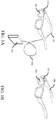
- FIG. 1A and FIG. 1B show two possible embodiments of the invention.
- FIG. 1A is a drawing of a possible embodiment of the present invention showing simple and lightweight eyewear integrated with the scanning display.
- a layer of holographic material is coated onto one of the lenses of the glasses 101.
- the HOE can be a photopolymer coated on the lens and subsequently holographically recorded or in another embodiment, the photopolymer can be embedded into (i.e., sandwiched) between two surfaces of the spectacle lens.
- the holographic material then acts to redirect the display light into the eye, while transmitting the light from the environment
- a scanning mirror or panel microdisplay projector 102 pyro-jects the image onto the holographic transtlector 101.
- the light source, power electronics and driver electronics are separately or altogether moved off the head in a small box 103 connected to the eyewear through a patch cord 104 which can be detached at the glasses by a removable connector 105. Moving these components off the head has the advantage of allowing the eyewear to be simple, lightweight, discrete, cosmetically attractive and socially acceptable. Further, the eyewear can be disconnected from the separate module allowing a user to indicate to others whether or not the personal display device is active.
- FIG. 1B is a drawing of another possible embodiment where the light source, power electronics and driver electronics are contained completely within the eyewear 106. Further, in other embodiments light can be projected into both eyes in a binocular fashion using two sets of projectors and HOEs on both spectacle lenses.
- FIG. 2A is a schematic of the optical arrangement of a scanning projection based head worn display for a single exit pupil of the scanning micro 212.
- Light of at least one wavelength 206 is incident on a scanning mirror 205, which scans the light beam in angle 207 with intensity modulated to correspond to a digital image.
- the holographic transflector 204 which in at least one embodiment includes a recorded holographic material 201 sandwiched between two outer protective layers 202 and 203, reflects the projected light 207 into diffracted light 208 toward the center of the eye entrance pupil 210 of the forward gazing eye 209.
- FIG. 2B shows that an eye can rotate out of the view of the single exit pupil.
- a single exit pupil arrangement is suitable for small field of view displays where the user aligns their eye to view the displayed images.
- the eye line of sight 211 is misaligned to the single exit pupil 212.
- the holographic transflector 204 reflects the projected light toward the center of the entrance pupil of the forward gazing eye but mismatch between the eye's entrance pupil 210 and the exit pupil 212 prevents the image from being seen.
- multiple exit pupils effectively expand the system's eyebox.
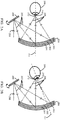
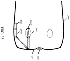
- FIG. 3A and FIG. 3B show an example of a multiple exit pupil arrangement, with two exit pupils created at two spatially separated positions near the eye.
- two exit pupils are shown for simplicity, but additional exit pupils can be used in a two-dimensional arrangements
- Multiple exit pupils can be used to create a larger effective eyebox for the eye, and allow for large FOV images to be scanned by the eye.
- multiplexing the holographic element with different wavelengths of light creates the multiple exit pupils.
- Volume holographic elements exhibit "selectivity" meaning that the hologram written for one wavelength of light and angle of incidence is independent of another hologram written at a sufficiently different wavelength or incidence angle.
- sources of different center wavelength or incidence angle can be used to produce multiple independent exit pupils without crosstalk thus producing an enlarged effective eyebox.
- the multiple exit pupils can be created with separated wavelengths of similar color in terms of human perception. For example, several exit pupil locations can be created using several different red light sources with sufficiently different center wavelengths. The required separation depends on the spectral selectivity of the HOE to prevent crosstalk.
- FIG. 3A is a schematic of the optical arrangement for two exit pupils 212 and 304 along the vertical axis created by holographic multiplexing of two light beams 206 and 301 of different wavelengths. These light beams are reflected by the scanning mirror 205, which scans the light beam in angles 207 and 302 with intensity modulated to correspond to a digital image
- the holographic transflector 204 reflects the projected light 207 and 302 into diffracted light 208 and 303 toward two exit pupil locations 212 and 304 at the plane of the eye, providing a tolerance to eye rotation.
- the eye line of sight 211 is aligned 211 to the center of the central exit pupil 212.
- FIG. 3B is a schematic of the optical arrangement for two exit pupils along the vertical axis with the eye line of sight 211 rotated but still capturing light from one of the exit pupils 304.
- each position of the scanning mirror can project independent pixel data for the different wavelength sources corresponding to the shifted positions of the exit pupils.
- the required image processing for laterally shifted exit pupils is primarily a relative image shift between the projected images for each of the different wavelengths sources.
- FIG. 4 is an illustration of the pre-processing shifts and image registration necessary to align on the retina the images of the different exit pupils.
- FIG. 4A shows two images 401 and 402 from two different exit pupils arranged vertically
- FIG. 4B pixels 404 and 405 content the information of the same image pixel for each exit pupil.
- pixels 404 and 405 By projecting pixels 404 and 405 on the transflector with a separation distance similar to the separation distance of the two corresponding exit pupils, pixels 404 and 405 merge into one single pixel 406 on the retina.
- Real systems can have additional shifts across 2-dimensions. Real systems may also benefit from further pre-processing of the images to correct nonlinearities such as distortion to improve alignment of the image
- FIG. 4D A demonstration of the enlarged eyebox and image pre-processing is shown in FIG. 4D .
- the image 407 with a single wavelength component corresponding to a single exit pupil was projected onto the transflector, which in turn reflected the image back into a camera combined with a focusing lens mimicking an artificial eye.
- Picture 408 was taken with the camera aligned with the single exit pupil, whereas picture 409 was taken with the camera partly misaligned with the single exit pupil and picture 410 was taken with the camera further misaligned with the single exit pupil.
- Picture 408, 409 and 410 show that the projected image disappears as the camera is misaligned with the single exit pupil.
- the image 411 with a different wavelength component than image 407 corresponding to another exit pupil than the one obtained from image 407 was projected together with image 407 onto the transflector, which in turn reflected the image back into a camera combined with a focusing lens mimicking an artificial eye.
- Picture 412 was taken with the camera aligned with the exit pupil of image 407, whereas picture 413 was taken with the camera partly misaligned with the exit pupil of images 407 and 408.
- Picture 414 was taken with the camera further misaligned with the single exit pupil but aligned with the exit pupil of image 408 .
- Picture 412, 413 and 414 demonstrate that the eyebox can be enlarged through the use of multiple exit pupils.
- FIG. 5 is an illustration of how the individual exit pupils are related to the "eyebox" of the head worn display.
- the system of FIG. 3A and FIG. 3B is shown with two exit pupils.
- Each exit pupil 212 and 304 creates a rotation tolerance for the eye, where the image can be viewed while light enters the eye's entrance pupil 210.
- the size of each individual eyebox 501 and 503 is approximately equal to the size of the eye's entrance pupil 210 when the exit pupil is located at the entrance pupil of the eye.
- two exit pupils are used to create a seamlessly enlarged effective eyebox in the vertical direction.
- the number and geometric arrangement of multiple exit pupils created at the eye can be widely varied and a large number of combinations are possible.
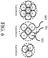
- FIG. 6 is an illustration of three possible arrangements made with multiple exit pupils 502 .
- the eyebox 501 covered by the multiple exit pupil's coverage improves approaching that of a larger synthetic exit pupil 601.
- Several example arrangements are shown for emphasizing particular locations on the screen such as the center and corners (3, 5 and 7 positions).
- the corresponding eyebox 501 for each exit pupil - shown as larger black circles - will be larger than the individual exit pupils and roughly the size of the eye's entrance pupil. If the individual eyeboxes associated with each exit pupil location overlap one another the overall effective eyebox can be made continuous without gaps in the viewable image space.
- exit pupils are shown as small circles, but can range in size depending on the size of the scanned beam.
- the invention includes but is not limited to these arrangement
- the most desirable solution may be a large number of exit pupils to fully cover the desired eyebox, i.e., 5 and 7 exit pupils in FIG. 6 .
- the different exit pupils should be arranged within a triangular lattice.
- simpler solutions can be found by explicitly selecting which parts of the human vision and eye rotation the multiple exit pupils cover. For example with 2 exit pupils, a single corner and the center of the eye's rotation can be used. This would be useful for displaying information in one corner of the person's field of vision viewable with both foveal and peripheral vision.
- the exit pupils can be non-overlapping in field of view or they can be overlapping.
- Volume hologram can be effectively wavelength multiplexed provided that hologram is selective enough to prevent crosstalk between adjacent channels.
- the selectivity of the hologram can be tuned controlling refractive index variation of the material and material's thickness. This selectivity applies to both the wavelength of the reconstruction light, and also the incidence angle of the reconstruction light with respect to the recording light.
- selectivity and tolerance to spectral and angular misalignment between the hologram recording and the read-out when used as a head worn display In the design of a multiplexed head worn display there is subsequently a trade-off between selectivity and tolerance to spectral and angular misalignment between the hologram recording and the read-out when used as a head worn display.
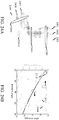
- FIG. 7 showing the diffraction efficiency of holographic transflectors in ordinate versus wavelength in abscissa as calculated by an analytic mathematical model, is an illustration of the wavelength selectivity of a volume holographic element made in a photopolymer.
- three holograms are multiplex recorded at three center wavelengths in the red: 643 nm - reference sign 701 -, 658 nm - reference sign 702 - and 671 nm - reference sign 703 - using a modeled refractive index variation of 0.0075 and a 60 ⁇ n hologram thickness.
- the recorded holograms show high wavelength selectivity 704, 706 and 706 for low crosstalk readout.
- the display can be made full color by using red, green and blue light sources.
- the required number of individually controlled light bands is 3 the number of desired exit pupil location For example, 3 light bands for one exit pupil and 21 light bands for 7 exit pupils.
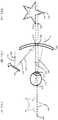
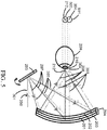
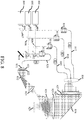
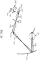
- the holographic transflector is recorded using an optical holographic recording setup shown in FIG. 8 .
- This setup creates a reflection hologram on the curved HOE.
- FIG. 8 is a schematic of the holographic writing setup shown with three wavelengths of similar color but different center wavelengths 801, 802 and 803 for three exit pupil locations 829 relative to a holographic material 824 collocated with the eye in the head worn display.
- the beams from the lasers are split with polarizing beam splitters 807, 808 and 809 and coupled by focusing optics 813, 814, 815 and 816 into fibers 817, 818, 819 and 820.
- the object beams 830 pass through lenses 827 and 825, are reflected by mirror 828, and pass through a polarizer 826 before passing through the holographic material 824 and focusing at the exit pupil locations 829.
- the reference beams 831 pass through lenses 821 and 823, a polarizer 822 and are reflected by a mirror 832 before passing through the holographic material 824.
- all laser wavelengths are combined and presented to the HOE using the angles of incidence and positions of the scanning projector.
- the lasers are coupled into individual optical fibers, which are spatially arranged and relay imaged through the HOE to create the multiple exit pupils at the eye location. Although three laser sources are shown, the setup can be scaled for additional wavelengths.
- the recording setup of FIG. 8 can be used as a "simultaneous" recording setup, where the multiplexed holograms are written at the same time. Simultaneous recording has advantages in terms of holographic efficiency homogeneity and a one-shot recording schedule. Other embodiments of the invention could alternatively use sequential recording to multiplex holograms, where multiple recordings are done one after another Another method is to record each holographic film with one wavelength or a set of wavelengths and subsequently place the films on top of each other.
- FIG. 9A is a schematic of a diffractive method for beam combining multiple LED or light sources of different center wavelengths 902, 903, 904, 905 and 906. These sources may be contained within a single controlled source 901.
- a lens 907 focuses laterally separated beams before reflecting from a diffractive element 908, which serves to co-align the beams of different wavelength before being focused by a lens 909 for a collimated output 910.
- FIG. 9B is a schematic of a dichroic beam combiner for collimated light sources of different center wavelengths 912, 913, 914, 915 and 916.
- FIG. 9C is a schematic of a volume holographic beam combiner for collimated light sources of different wavelengths.
- Light sources of different wavelengths 919, 920, 921, 922 and 923 are coaligned by a volume holographic element 924 for an axially combined beam 925.
- FIG. 9D is a schematic of a volume holographic beam combiner using an external cavity to create a multi-wavelength laser source.
- Each of the sources 926, 927, 928, 929 and 930 has an antireflection coating to prevent lasing within its internal cavity, and incident onto a holographic beam combiner 931. Instead, an external partially reflective mirror 932 forms a cavity for all sources for collimated output 933.
- the advantage to this approach is decreased sensitivity to temperature variations.
- the present invention relates to a head worn display with wavelength separated light sources that are combined in a non-coaxial way to create relative angle shifts between light from each source after leaving the scanning micromirror.
- Light from independent sources with appropriately separated wavelengths can be multiplexed in wavelength in the holographic transtlector to produce spatially separated exit pupils (and equivalently spatially separated eyeboxes) at the eye. If light from the sources is coaxially combined, then significant preprocessed digital image shifts are required to align the apparent images from the different exit pupils at the eye.
- FIG. 10 shows a scanning projector based head worn display on an eyewear frame 1001 that creates two exit pupils 1005 and 1006.
- both exit pupils are contained within a single large entrance pupil 210 of the eye 209.
- Two independent sources of different center wavelengths are scanned by scanning projector 1002 creating shifted beams, which are reflected by a multiplexed holographic transflector 204 to the eye 209.
- the chief rays 1003 and 1004 of the two sources are shown in solid and dashed lines for the two wavelengths.
- the source combiner to create non-coaxially combined light sources consists of a spatially distributed ensemble of light sources and a telecentric combiner lens which combines the sources at the exit pupil of the telecentric lens which coincides with the scanning micromirror.
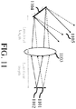
- FIG. 11 shows an optical apparatus to combine the multiple wavelength sources with predetermined angles to present them to the hologram. In this illustration two sources are shown, 1101 and 1102 of different center wavelengths. The sources are accurately placed and arranged on a single plane such that their spatial positions are transformed into angular separations by a telecentric lens 1103 which has its exit pupil collocated with the scanning micromirror. 1104. After reflection from the micromirror.
- light 1105 travels to a projection lens (not shown) to focus the light for presentation to the hologram transflector such that the light is collimated or nearly collimated at the eye.
- the angles between the separate sources are designed such that the preprocessed image shifts necessary to align the different images from each exit pupils at the eye is minimized.
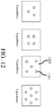
- the sources are arranged with precision alignment such that their orientation creates the necessary angular separation after leaving the micromirror to minimize image processing shifts. These sources can be arranged in a variety of orientations including but not limited to those shown in FIG. 12.
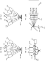
- FIG. 12 shows four possible source arrangements that could be used with the apparatus of FIG. 11 .
- Each source emitter 1201 in this case can be similar in apparent colour, red for example, but separated in wavelength from its neighbours, or a combination of red, green and blue as shown in FIG. 13A .
- the sources can be surface mount emitters such as but not limited to vertical cavity surface emitting lasers (VCSELs), LEDs, Superluminescent LED's (SLED's) or resonant cavity LEDs (RCLEDs) of different wavelengths which are aligned with precision in a single electronic package using a precision pick and place method.
- VCSELs vertical cavity surface emitting lasers
- SLED's Superluminescent LED's
- RCLEDs resonant cavity LEDs
- broadband sources are created and spatially arranged using a monolithic fabrication method and then modified to narrow their bandwidth using wafer scale spectral filters and optics.
- a full color exit pupil is created by closely spacing red, green and blue sources for each exit pupil location in a single electronic package.
- FIG. 13A shows an embodiment of the invention to extend the angularly shifted source of FIG. 12 to full colour.
- An emitter ensemble 1202 is shown with three separated emitter positions 1301, 1302 and 1303 as in the far left example in FIG. 12 .
- red, green and blue (RGB) emitters are arranged closely to form approximately a single emitter position.
- the emitter position 1301 is constituted of red emitter 1304, green emitter 1305 and blue emitter 1306. Additional RGB wavelengths form the other separated emitters 1302 and 1303 to ultimately create a three-exit pupil composite eyebox.
- FIG. 13B shows how the slightly shifted RGB emitters for a single eyebox create slightly angle shifted scans at the eye, producing the image 1307 on the retina.
- image preprocessing can be used to align the images into a single apparent color image with an expanded composite eyebox 1305 .
- red, green and blue light sources are combined using a dichroic beam combiner.
- FIG. 14 shows the optical apparatus to non-coaxially combine the multiple wavelength sources from three panels 1401, 1402 and 1403 using a prism dichroic beam combiner 1408.
- sources 1101, 1102, 1404, 1405, 1406 and 1407 are shown in a configuration with two sources for each panel at different center wavelengths.
- the sources are accurately placed and arranged on a single effective plane such that their spatial positions are transformed into angular separations by a telecentric lens 1103 which has its exit pupil collocated with the scanning micromirror 1104.
- light 1409 travels to a projection lens (not shown) to focus the light for presentation to the hologram transflector such that the light is collimated or nearly collimated at the eye.
- the angles between the separate sources are designed such that the preprocessed image shifts necessary to align the different images from each exit pupils at the eye is minimized.
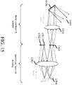
- spectral filtering may be required to reduce the bandwidth of each emitter. In at least one embodiment this can be achieved using a spectral filtering section such as but not limited to the implementations shown in FIG. 15 .
- the source array constituted of sources 1501 and 1502 would be as described previously in FIG. 12 or FIG. 13 , however this source would be first reimaged onto a spatial filter mask 1505 after double passing through a lens and reflecting from a diffraction grating 1504 .
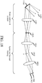
- FIG. 15 shows an optical apparatus to non-coaxial beam combine and project which includes the angular- combiner of FIG. 11 along with a spectral and spatial bandwidth filter section.
- the spectral and spatial filter sections could be applied to the RGB combiner of FIG 14 .
- the spatial and spectral bandwidth sections prevent crosstalk when more broadband sources such as LEDs and resonant cavity LEDs are used.
- Light sources separated in wavelength and position 1501 and 1502 project to a lens 1503 and then to a diffraction grating 1504 to disperse light from each emitter in angle and then filter both spatially and spectrally the conjugate image using an aperture mask 1505.
- the angular combiner of FIG. 11 combines the beams as described previously.
- the light source implementation shown in FIG. 15 can be compactly implemented into eyewear by mounting the assembly within the arm of the eyewear.
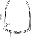
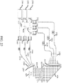
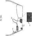
- FIG. 16 shows a conceptual monocular HWD arrangement using the angular source combiner and spatial and spectral filters 1601 of FIG. 15 .
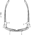
- FIG. 17 shows a conceptual binocular HMD arrangement using two of the angular source combiners and spatial spectral filters 1601 and 1701 of FIG. 15 .
- This arrangement also includes two holographic transflectors 1602 and 1702 on each spectacle lens and two projection lenses 1603 and 1703.
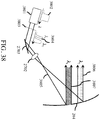
- the spectral and spatial filtering implementation can be done in a transmissive rather than reflective arrangement, such as but not limited to the implementation shown in FIG. 18 .
- the angular combiner of FIG. 11 combines the beams as described previously.
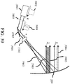
- a multiplexed reflection holographic element can be used to perform spectral filtering on the light emitted from broadband sources before reflecting from a scanning mirror, such as but not limited to the implementation shown in FIG. 19 .
- light sources separated in wavelength and position 1501 and 1502 project to a lens 1901 and then to the multiplexed reflective volume hologram 1902.
- Diffracted beams from the HOE 1902 are filtered spectrally by the recorded volume hologram before being transporter to the scanning mirror 1104 and then to an aperture filter 1903.
- the direction of the light can also be adjusted by grating slant.
- the present invention of multiple exit pupils created with a holographic element relates to a head worn display created using a microdisplay panel rather than a scanning mirror projection system.
- the panel microdisplay is illuminate by a source such as an LED or a laser light source and projected toward the eye forming a conjugate image of the microdisplay on the retina.
- This holographic transflector element performs two primary functions. It allows ambient light from the environment to pass through providing normal vision to the user. It also redirects scanned light from the projector to the eye to provide an image on the retina.
- the introduction of multiple small beams forming a composite exit pupil reduces the étendue of the light beams compared to prior art (see Figure 2 , US patent 4,940,204 ). This has two signiticant effects:
- a field sequential color LCOS microdisplay is used to project the different wavelengths of light onto the hologram to create multiple exit pupils. Sources of different colors are combined and presented to the microdisplay.
- the microdisplay cycles through the colors sequentially such that the time to project all the wavelengths constitutes one video frame. This requires that the microdisplay refresh at a rate at least equal to (the number of wavelengths)*(the desired video rate).
- the microdisplay then displays a shifted and distortion corrected image for each wavelength such that the images are combined to form a single image at the eye due to persistence of vision (see FIG. 4 ).
- a simple eye tracking system is used to preferentially activate the exit pupil best aligned to the eye. This has the advantage of reducing the required refresh rate of the microdisplay and power consumption of the light sources when using field sequential color since only the subset of wavelengths for a single exit pupil needs to be displayed at any moment in time.
- the projection optics used to transfer light from the microdisplay to the hologram use tilted, shifted, aspheric and non-rotationally symmetric optical elements to pre-compensate for aberrations formed by the off-axis projection and the hologram's reflection
- the hologram recording setup (shown in a simplified configuration in FIG. 8 ) will utilize tilted, shifted, aspheric and non-rotationally symmetric optical elements to optimize the hologram for readout in the HWD with low optical aberrations.
- the joint optimization of the projection optics and hologram recording reduces the aberrations of the arrangement to form low aberration and high quality images on the retina.
- a light-emitting panel such as an OLED is used.
- the pixel structure-whether stacked or side-by-side for different emission colors- creates the multiple wavelengths necessary to create the multiple exit pupils at the eye.
- Each set of similar wavelength pixels is individually controlled to produce a properly shifted and distortion pre-compensated image for projection onto the hologram and subsequently to the user's eye forming a single apparent monochrome or color image using the different wavelength
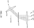
- FIG. 20 shows the multiple exit pupil arrangement with a panel microdisplay rather than scanning projector Light from a microdisplay 2002 within a projection module 2001 is projected through projection optics 2003 onto a multiplexed holographic screen 204.
- the holographic screen 204 is multiplexed in wavelength to separate each wavelength to create multiple exit pupils as also described in FIG. 3 thru FIG. 7 .
- a single image is created at the eye by preprocessing the images as shown in FIG. 4 .
- the projection optics 2003 consist of an arrangement of optical elements necessary to present light to the holographic element 204 such that the holographic element reflects nearly collimated light toward the eye with low aberrations.
- These optical elements of the projection lens consist of, but are not limited to lenses, mirrors, freeform elements, shifted and tilted elements, aspheric lenses and mirrors, non-axisymmetric lenses and mirrors and prisms
- Three light field positions 2004 are shown projected from the projector. After reflection from the holographic reflector 204, three angularly separated beams 2005, 2006 and 2007 form spatially separated exit pupils at the eye 209.
- the present invention relates to system and method for placing two or more exit pupils on the eye with control over their locations such that
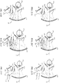
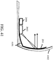
- FIG. 21 A shows an optical schematic of the scanned retinal display with the eye aligned to one of two separated exit pupils with separated field of view created with a single wavelength beam 2101.
- the single wavelength beam is incident on the scanning mirror 205 which divides the overall field of view into the on-axis see-through display light 2104 and the glance-at off-axis light 2105 .
- Both sets of beams reflects from the holographic reflector 204 forming converging light bundles 2102 and 2103 which form the two exit pupils at the eye 209.
- the eye line of sight 211 is aligned to the on-axis see-through light 2102.
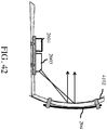
- FIG. 21B shows the same system as FIG. 21A but with the eye line of sight 211 aligned to the glance-at off-axis light 2103.
- FIG. 21C shows an optical schematic of the scanned retinal display with the eye line of sight aligned to one light bundle 2108 with partly overlapping field of view from a second light bundle 2109 created with two wavelength beams 2106 and 2107. Recording and reading the HOE by different wavelengths or sets of wavelengths makes the differentiation between the on-axis see-through sub-display and the off-axis glance-at sub-display.
- FIG. 21C shows an optical schematic of the scanned retinal display with the eye line of sight aligned to one light bundle 2108 with partly overlapping field of view from a second light bundle 2109 created with two wavelength beams 2106 and 2107. Recording and reading the HOE by different wavelengths or sets of wavelengths makes the differentiation between the on-axis see-through sub-display and the off-axis glance-at sub-display.
- both the on-axis see-through sub-display field of view and the off-axis glance-at sub-display field of view can be overlapped allowing the user to view alerts in the off-axis glance-at sub display while looking straight ahead.
- the MEMS scan mirror projects light over a broad enough angular range to display information for both the on-axis see-through sub-display and the off-axis glance-at sub-display, as shown in FIG. 21A - FIG. 21D . Both the position at which the light impinges on the HOE and the light wavelength discriminate in which exit pupil the light is redirected, thus for which sub-display the light is sent to.
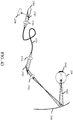
- FIG. 21E shows an optical schematic of the scanned retinal display with the eye aligned to one light bundle 2114 with a separate field of view from a second light bundle 2115 created with two light sources separated in position and angle 2112 and 2113 .
- Light generated from one particular position impinges on the HOE so as to be used for the on-axis see-through sub-display, while light generated at another position impinges on the HOE so as to be used for the off-axis glance-at sub-display.
- FIG. 21E shows an optical schematic of the scanned retinal display with the eye aligned to one light bundle 2114 with a separate field of view from a second light bundle 2115 created with two light sources separated in position and angle 2112 and 2113 .
- Light generated from one particular position impinges on the HOE so as to be used for the on-axis see-through sub-display, while light generated at another position impinges on the HOE so as to be used for the off-axis glance-at sub-disp
- a flip mirror 2120 modifiers the incident angle of the light impinging on the scanning mirror 205, thus modifying at which position light beams impinge on the HOE.
- Light can then be sent to the area providing an off-axis glance-at sub-display for a given position of the flip mirror, or be sent to the area providing an on-axis see-through sub-display.
- multiple scanning mirrors create multiple exit pupils at the location of the eye by reflecting from a holographic optical element.
- the hologram is angle multiplexed for the multiple exit pupils.
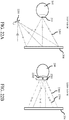
- FIG. 22A is a top view optical schematic of the scanned retinal display with two scanning mirrors (only one visible) 2201, where light from two different angles reflects from the hologram 204 back to the eye 209 to create two separated exit pupils at the eye.
- FIG. 22B shows the side view of the same system of FIG. 22A where the two scanning mirrors 2201 and 2202 create two separated beams 2203 and 2204 which in turn create two independent exit pupils at or near the eye's location.
- FIG. 22A is a top view optical schematic of the scanned retinal display with two scanning mirrors (only one visible) 2201, where light from two different angles reflects from the hologram 204 back to the eye 209 to create two separated exit pupils at the eye.
- FIG. 22B shows the side view of the same system of FIG. 22A where the two scanning mirrors 2
- FIG. 23 shows a setup to record the angularly multiplexed holograms for the multiple exit pupil head worn display of FIG. 22A .
- This figure is similar in many respects to the wavelength-multiplexed embodiment of FIG. 8 .
- Each laser used is split into two beams, which would interfere into the holographic film
- each light source send light to the hologram from distinct locations, resulting in different incidence angle at every position of the holographic film
- each beam incident on a position of a then recorde dHOE is stirred into its corresponding eyebox.
- the beams from the lasers are split with polarizing beam splitters 807, 808 and 809 and coupled by focusing optics 2303 into fibers 2304.
- the object beams 2306 pass through lenses 827 and 825, are reflected by a mirror 828, and pass through a polarizer 826 before passing through the holographic material 824 and focusing at the exit pupil locations 829.
- the reference beams 2305 pass through a polarizer 2307 prior the holographic transflector 824.
- the lasers are presented to the HOE using the angles of incidence representative of the multiple scanning mirror
- the lasers are spatially presented to the HOE to create the multiple exit pupils at the eye location.
- three laser sources and multiplexed angles are shown, the setup can be scaled for additional multiplexed holograms.
- two collimated or nearly collimated beams incident each side of the HOE interfere to produce a reflective hologram for a non-pupil forming head worn display.
- the head worn display is referred to as non-pupil forming since no intermediate image is formed in the optical system.
- a consequence of this type of arrangement is that field of view is limited, and more difficult to increase than the eyebox.
- the field of view can be increased using two or more sets of collimated or nearly collimated beams incident on opposite side of the holographic film interfere on the holographic film to produce a reflective hologram as shown in FIG. 24A .
- Each set is constituted of two beams previously split from the same coherent light source.
- the HOE is multiplexed angularly.
- FIG. 24A shows three sets of beams.
- the reference beams 2407, 2408 and 2409 are collimated by a lens 2406 and incident on the holographic material 2405.
- the object beams 2401, 2402 and 2403 are collimated by a lens 2404 and incident on the opposite side of the holographic material 2405.
- the then recorded holographic transflector will produce exit pupils whose location 2410 will be below the holographic material.
- FIG. 24A shows three sets of beams.
- the reference beams 2407, 2408 and 2409 are collimated by a lens 2406 and incident on the holographic material 2405.
- the object beams 2401, 2402 and 2403 are collimated by a lens 2404 and incident on the opposite side of the holographic material 2405.
- the diffraction efficiency 2413 and 2414 in function of wavelength are shown for two different holographic transflectors as calculated by an analytic mathematical model.
- the diffraction angles 2411 and 2412 of the two holograms as a function of incidence angle are also shown. Because the holograms are closely matched in their incidence angle to diffracted angle, they can be combined for a contiguous overall field of view.
- the diffracted angle is of 3.304° for both the holographic transflector recorded with a reference beam angle of 45° and the holographic transflector recorded with a reference beam angle of 55°.
- the non-pupil forming HOE is multiplexed spectrally rather than in angle FIG.
- the object beam is made up of three spatially separated sources 2501, 2502 and 2503 of three different wavelength which are collimated by a lens 2504 and brought together on the holographic material 2505.
- the reference beam contains the three wavelengths beam combined into a single recording beam 2407, which is collimated by a lens 2506, and then incident on the holographic material 2505.
- the then recorded holographic transflector will produce exit pupils whose location 2508 will be below the holographic material.
- FIG. 26 shows a drawing of a scanning projection monocular head worn display on an eyewear frame 2601. Light emitted from a light source 2604 is projected by scanning mirror and focusing optics 2603 before being deflected by a transflector element 204 to the eye 209. Display light is focused on the retina 2602.
- FIG. 27 describes an imaging system based on a confocal microscope arrangement. Collimated light from the light source 2709, which contains one or more light sources, is focused by a first lens 2706 on a pinhole 2705. Light from the pinhole is collimated by a lens 2704 and scanned by a scanning mirror 2703 in two dimensions. The light is directed and passes through a lens 2702 to an appropriate holographic transflector 204, which can be a volume holographic element, a diffractive optical element (relief) or a curved reflective element with frequency selective response.
- holographic transflector 204 can be a volume holographic element, a diffractive optical element (relief) or a curved reflective element with frequency selective response.
- the light is focused on one point on the retina 2602. A part of this light is reflected back, either at the same wavelength (Rayleigh scattering), by fluorescence, Raman or by non-linear phenomenon (frequency shifted from the incident light).
- the beam propagates back 2701 and is reflected by the holographic transflector.
- the holographic transflector In case of frequency shifted light, the holographic transflector has an appropriate reflection at the shifted frequency. Since the image of the pinhole is the point on the retina where the light is focused, the pinhole will block light that is not coming from this focus. This is the basic principle of confocal microscopy. It allows rejection of stray light and scattering light from other parts of space.
- FIG. 28 shows a variation of FIG. 27 .
- the holographic transflector reflects the incident beam of a particular wavelength and focuses it 2801 in a different part of the eyeball (different than the retina). This way, other structures of the eye can be imaged. For example, light beam 2801 can be focused on the crystalline lens of the eye.
- FIG. 29 shows yet another variation
- the visible head worn display is not perturbed (the transflective screen does not modify visible light in this case).
- Images of the retina 2602 are obtained by one dedicated detector 2903 and images of other parts (e.g. lens) are obtained with another detector 2902 since the information is encoded spectrally in different color and then detected separately.
- a diffraction type beam splitter is used to separate the infrared and visible light 2901.
- a beam splitting filter 3001 which can be, but not restricted to, of interference type, dichroic, holographic.
- a fiber optic is used in place of the pinhole aperture as shown in FIG. 30 .
- the light source is displaced to a different location from the scanning mirror, allowing for more flexibility in the eyewear design
- the fiber itself is one from the following list a single mode fiber, a multimode fiber or a dual cladding fiber, which includes both a single mode core and a larger multimode core.
- the single mode core is used to project light into the HWD with high resolution, while the multimode core is used to collect the confocal return signal. This allows a larger aperture to be used for the confocal return signal for increased signal to noise without sacrificing display resolution.
- the above embodiments are used to image the eye. Because the retina can be imaged, the veins can be identified and thus parameters such as the flow of blood cells, heart rate and arterial pressure (systolic, mean and diastolic) can be measured using a number of ways. Heart rate can be measured, but not limited to, by using the small reflectivity changes caused by the varying blood volume occurring while the heart is pumping blood.
- a precise region (such as a vein) can be isolated from the other part of the eye to extract the signal with a high signal to noise ratio.
- Hemoglobin concentration oscillates with time as a result of the arterial pulsation associated with the systolic-diastolic pressure variation.
- a spectroscopic optical measurement of the backscattered light from a vein is another method to obtain arterial pulsation.
- the spectroscopic measurement can be obtained by using two or more wavelength (such as for example two available in the red of the HWD invention.
- FIG. 31 is an image of the retina taken with a standard ophthalmoscope (microscope adapted for the eye). The veins can be clearly seen.
- FIG. 32 illustrates the different parts of the retina that would be seen by an ophthalmoscope such as described in FIG. 27 to FIG. 30 .
- the different images 3201, 3202 and 3203 correspond to different gaze directions. One can see that the images have features that are clearly unique to gaze direction. Features can be extracted from the images that are unique markers and that can be used as unique identifiers of the image representing a gaze direction and thus can be used as an eye tracker. The features are not restricted to images of the retina.
- FIG. 33 is a block diagram describing the methodology for eye tracking: first the system has a calibration routine. The calibration could be done at intervals. The cycle depends on the rate of change of the features and adapted in consequence. The calibration consists of grabbing images of the retina when the user performs different gaze directions. For example, the user is asked to fixate a feature displayed on the head worn display and that moves to cover a set of gaze directions. Features are then extracted from the images to form a reduced number of unique image identifier A database of features corresponding to each gaze direction is formed. By reducing images to unique features, less memory is used.
- eye-tracking is performed by first grabbing an image (retina or other) and then this image is correlated against the images in the database. Then a classification algorithm determines which image in the database the newly grabbed image most resembles. One method is to select the image with the highest correlation.
- Another use of the anatomy of the retina is for relating intra ocular pressure (IOP) to optic disc displacement. It has been shown that optical disc displacement is related to ocular pressure. Thus by monitoring the location of the optical disc (region near the optic nerve in FIG. 31 ) continuously, information related to ocular pressure which is a major cause for glaucoma, can be extracted.
- IOP intra ocular pressure
- eye-tracking is realized by monitoring the intensity of the light reflected by the eye corresponding to each exit pupil.
- FIG. 34 showing 3 exit pupils, but not limited to, only the light corresponding to one exit pupil 3401 passes through the eye entrance pupil 3402, the light corresponding to the other exit pupils 3403 and 3404 is blocked.
- the confocal imaging system will only give an appreciable signal from the exit pupil 3401 that is aligned to the eye entrance pupil 3402.
- the relative intensity ratio at the detectors gives a measure of the gaze direction.
- FIG. 34 shows a front view of exit pupils are related to the "eyebox.”
- FIG. 35 shows an implementation of a multiple exit pupil head worn display with a camera 3501 positioned to look directly in front of the user.
- the camera grabs a scene 3601 and provides a zoomed version of the scene 3604 to the head worn display.
- people with low vision such as, but not limited to, cases of age related macular degeneration (AMD) for which there is a loss of visual acuity in the fovea but the peripheral vision is not affected can benefit from having an image zoom option in order to better see details that otherwise they would not be able to see in their macular region 3602 without the zoomed digital image.
- AMD age related macular degeneration
- the loss of peripheral vision can be circumvented by having a camera 3501 grab an image which is then processed so as to extract useful information (such as objects outside the peripheral vision of the patient). This information is then displayed on the glasses in the foveal region so as to give the patient awareness of the surrounding he/she cannot see.
- other sensors than a camera which is sensitive in the visible or infrared spectral region
- sensors such as, but not limited to, position sensors (incl accelerometers), GPS sensors, pressure sensors or any type of sensor that can locate the position in space of the wearable glass.
- an eye tracking system such as, but not limited to, the system described in this application and by using a binocular projection display, for example a system such as but not limited to, with multiple exit pupil (one for each eye)
- a binocular projection display for example a system such as but not limited to, with multiple exit pupil (one for each eye)
- the positioning sensors locate the position of the eyewear with respect to a scene (e.g. recorded digitally by the camera).
- the eye tracking system determines the object of interest in the scene.
- FIG. 37 illustrates embedded small kinoform mirrors 3701 and 3702 in a transparent matrix 3703 which can be any suitable thermo plastics (e.g. Poly Carbonate, PMMA).
- the function of the small mirrors is to redirect a direction of light beam from the projector to the eye 209.
- the projector can be a scanning mirror or a fixed microdisplay (LCD, LCOS e.g.).
- the mirrors can be coated with a thin film so as to provide an adequate spectral reflection response.
- the spectral response of the embedded mirrors is reflective in the spectral band of the 3 light sources and transmissive everywhere else in the visible range.
- FIG. 38 illustrates another method for obtaining multiple exit pupils for the purpose of synthesizing a larger eyebox.
- a broadband 3802 light source 3801 such as but not limited to light emitting diodes of small emitting apertures (between 1 and 10 micrometers), resonant cavity light emitting diodes of the same small emitting aperture, laser diodes, super luminescent diodes and vcsels, is first spectrally sliced 3803 to produce a spectrum 3804 composed of discrete emission bands each separated by a spectral zone with no light.
- the resulting collimated light is then scanned by a 2D scanner 2703 which can be but not limited to MEMs scanner, resonant or non-resonant, acousto-optic deflectors, liquid crystal deflector.
- a projection lens 2702 is used to produce a diverging beam 3805 .
- a holographic transflector 204 recollimates the diverging beam according to the wavelength 3806 and 3807.
- the holographic transflector can be but not restricted to, a holographic element, a volume holographic element of the polymer, crystal or glass type.
- a polymer holographic material is preferred since it can laminated onto surfaces. Because the diverging beam is composed of multiple distinct wavelength bands (in the example of FIG.
- the reflection hologram has a thickness and is made in such a way as to diffract wavelength band 1 3807 to produce a collimated beam corresponding to a curtain angular range of the diverging beam.
- wavelength band 2 3806 is diffracted to produce a collimated beam which is propagating in the same direction as collimated beam of wavelength 1 but displaced spatially so as to produce an extended eyebox with multiple exit pupils.
- FIG 39 illustrates yet another method for obtaining multiple exit pupils.
- the same collimated light source 3801, as described in FIG. 38 is spectrally filtered 3804 and deflected by a 2D scanner 2703.
- the light beam is incident on a dispersive optical element 3901, such as, but not limited to, a transmission diffraction grating.
- the transmission grating produces two distinct diverging beams 3902 and 3903, corresponding to each wavelength band (two bands in the example illustrated in FIG. 39 ).
- the holographic transflector 204 of the same description as in FIG. 38 , produces two distinct re-collimated beams 3904 and 3905 corresponding to each wavelength band, which forms the extended eye-box with multiple exit pupils.
- FIG. 40 illustrates a multiple exit pupil projection system on each side of a pair of glasses 2601 (binocular or biocular).
- the left and right eye each receives an image from the respective projection system.
- three-dimensional information can be displayed in accordance with the gaze direction. Three dimensions comes from binocular view.
- a camera placed on the glasses 3501 grabs an image representing the view of the wearer.
- By calibrating the camera with the viewer's gaze angle it is then possible to augment the view with appropriate information
- a surgeon wearing the eyewear augmented information could be displayed directly onto the surgeon's gaze direction.
- the position of important arteries, not seen directly by the surgeon's real view could be overlayed.
- FIG. 41 is an embodiment of a rigid structure on which the projection system, i.e., source 2604, detector, scanner or microdisplay 2603 and holographic transflector 204 are placed on.
- the system is aligned on the rigid structure 4101.
- the rigid structure is then positioned (attached) to the frame 4102 of an eyewear which can be, but not limited to an eyewear with prescription glasses.
- the holographic transflector is placed between the projection system and the spectacle. The divergence of the beam coming off the holographic transflector can be adjusted to compensate for the user's eye prescription.
- FIG. 42 is another embodiment with the holographic transflector 204 placed on the outside of the spectacles 4101.
- the projection system comprising light source 2604, detector, scanner or microdisplay 2603 is attached on the side branch.
- the holographic transflector is secured such as but not limited to epoxied, clipped, screwed.
Landscapes
- Physics & Mathematics (AREA)
- General Physics & Mathematics (AREA)
- Optics & Photonics (AREA)
- Mechanical Optical Scanning Systems (AREA)
- Lenses (AREA)
Priority Applications (1)
| Application Number | Priority Date | Filing Date | Title |
|---|---|---|---|
| EP17198048.5A EP3296797B1 (en) | 2013-03-25 | 2014-03-25 | Method for displaying an image projected from a head-worn display with multiple exit pupils |
Applications Claiming Priority (3)
| Application Number | Priority Date | Filing Date | Title |
|---|---|---|---|
| IBPCT/IB2013/052347 | 2013-03-25 | ||
| IBPCT/IB2013/060218 | 2013-11-18 | ||
| PCT/IB2014/060134 WO2014155288A2 (en) | 2013-03-25 | 2014-03-25 | Method and apparatus for head worn display with multiple exit pupils |
Related Child Applications (1)
| Application Number | Title | Priority Date | Filing Date |
|---|---|---|---|
| EP17198048.5A Division EP3296797B1 (en) | 2013-03-25 | 2014-03-25 | Method for displaying an image projected from a head-worn display with multiple exit pupils |
Publications (2)
| Publication Number | Publication Date |
|---|---|
| EP2979128A2 EP2979128A2 (en) | 2016-02-03 |
| EP2979128B1 true EP2979128B1 (en) | 2017-10-25 |
Family
ID=50729734
Family Applications (2)
| Application Number | Title | Priority Date | Filing Date |
|---|---|---|---|
| EP14724151.7A Active EP2979128B1 (en) | 2013-03-25 | 2014-03-25 | Method for displaying an image projected from a head-worn display with multiple exit pupils |
| EP17198048.5A Active EP3296797B1 (en) | 2013-03-25 | 2014-03-25 | Method for displaying an image projected from a head-worn display with multiple exit pupils |
Family Applications After (1)
| Application Number | Title | Priority Date | Filing Date |
|---|---|---|---|
| EP17198048.5A Active EP3296797B1 (en) | 2013-03-25 | 2014-03-25 | Method for displaying an image projected from a head-worn display with multiple exit pupils |
Country Status (6)
| Country | Link |
|---|---|
| US (2) | US9846307B2 (enExample) |
| EP (2) | EP2979128B1 (enExample) |
| JP (1) | JP6449236B2 (enExample) |
| KR (1) | KR20150136601A (enExample) |
| CN (1) | CN106170729A (enExample) |
| WO (1) | WO2014155288A2 (enExample) |
Cited By (1)
| Publication number | Priority date | Publication date | Assignee | Title |
|---|---|---|---|---|
| WO2019192682A1 (en) | 2018-04-03 | 2019-10-10 | Huawei Technologies Co., Ltd. | Display device for head-mounting and display method |
Families Citing this family (304)
| Publication number | Priority date | Publication date | Assignee | Title |
|---|---|---|---|---|
| US20140198034A1 (en) | 2013-01-14 | 2014-07-17 | Thalmic Labs Inc. | Muscle interface device and method for interacting with content displayed on wearable head mounted displays |
| US10331207B1 (en) * | 2013-03-15 | 2019-06-25 | John Castle Simmons | Light management for image and data control |
| US9392129B2 (en) * | 2013-03-15 | 2016-07-12 | John Castle Simmons | Light management for image and data control |
| CN106170729A (zh) * | 2013-03-25 | 2016-11-30 | 英特尔公司 | 用于具有多个出射光瞳的头戴显示器的方法和设备 |
| US9582922B2 (en) | 2013-05-17 | 2017-02-28 | Nvidia Corporation | System, method, and computer program product to produce images for a near-eye light field display |
| US9519144B2 (en) | 2013-05-17 | 2016-12-13 | Nvidia Corporation | System, method, and computer program product to produce images for a near-eye light field display having a defect |
| JP6209456B2 (ja) * | 2013-05-31 | 2017-10-04 | 株式会社Qdレーザ | 画像投影装置及び投射装置 |
| US11921471B2 (en) | 2013-08-16 | 2024-03-05 | Meta Platforms Technologies, Llc | Systems, articles, and methods for wearable devices having secondary power sources in links of a band for providing secondary power in addition to a primary power source |
| US20150124566A1 (en) | 2013-10-04 | 2015-05-07 | Thalmic Labs Inc. | Systems, articles and methods for wearable electronic devices employing contact sensors |
| US10042422B2 (en) | 2013-11-12 | 2018-08-07 | Thalmic Labs Inc. | Systems, articles, and methods for capacitive electromyography sensors |
| WO2015081113A1 (en) | 2013-11-27 | 2015-06-04 | Cezar Morun | Systems, articles, and methods for electromyography sensors |
| US9594247B2 (en) * | 2013-12-19 | 2017-03-14 | Nvidia Corporation | System, method, and computer program product for a pinlight see-through near-eye display |
| US10303242B2 (en) | 2014-01-06 | 2019-05-28 | Avegant Corp. | Media chair apparatus, system, and method |
| US10409079B2 (en) | 2014-01-06 | 2019-09-10 | Avegant Corp. | Apparatus, system, and method for displaying an image using a plate |
| US11737666B2 (en) | 2014-01-21 | 2023-08-29 | Mentor Acquisition One, Llc | Eye imaging in head worn computing |
| US9759918B2 (en) * | 2014-05-01 | 2017-09-12 | Microsoft Technology Licensing, Llc | 3D mapping with flexible camera rig |
| WO2015169220A1 (zh) * | 2014-05-06 | 2015-11-12 | 宁波舜宇光电信息有限公司 | 转光三维成像装置和投射装置及其应用 |
| US9880632B2 (en) | 2014-06-19 | 2018-01-30 | Thalmic Labs Inc. | Systems, devices, and methods for gesture identification |
| US9874744B2 (en) | 2014-06-25 | 2018-01-23 | Thalmic Labs Inc. | Systems, devices, and methods for wearable heads-up displays |
| CA2962899C (en) * | 2014-09-29 | 2022-10-04 | Robert Dale Tekolste | Architectures and methods for outputting different wavelength light out of waveguides |
| GB201420352D0 (en) * | 2014-11-17 | 2014-12-31 | Vision Eng | Stereoscopic viewing apparatus |
| TWI588535B (zh) * | 2014-11-20 | 2017-06-21 | 英特爾股份有限公司 | 可調式焦距平面光學系統 |
| TWI688789B (zh) | 2014-11-20 | 2020-03-21 | 美商英特爾股份有限公司 | 虛擬影像產生器及投影虛擬影像的方法 |
| US9858676B2 (en) * | 2015-01-08 | 2018-01-02 | International Business Machines Corporation | Displaying location-based rules on augmented reality glasses |
| JP6439453B2 (ja) * | 2015-01-09 | 2018-12-19 | セイコーエプソン株式会社 | 画像表示装置、及び画像表示装置の製造方法 |
| US9958682B1 (en) | 2015-02-17 | 2018-05-01 | Thalmic Labs Inc. | Systems, devices, and methods for splitter optics in wearable heads-up displays |
| CN108351519A (zh) | 2015-02-17 | 2018-07-31 | 赛尔米克实验室公司 | 用于在可穿戴式平视显示器中进行适眼区扩大的系统、设备和方法 |
| NZ773815A (en) | 2015-03-16 | 2022-07-01 | Magic Leap Inc | Methods and systems for diagnosing and treating health ailments |
| US9823474B2 (en) * | 2015-04-02 | 2017-11-21 | Avegant Corp. | System, apparatus, and method for displaying an image with a wider field of view |
| US9995857B2 (en) | 2015-04-03 | 2018-06-12 | Avegant Corp. | System, apparatus, and method for displaying an image using focal modulation |
| CN113050280B (zh) | 2015-05-04 | 2024-01-19 | 奇跃公司 | 用于虚拟和增强现实的分离光瞳光学系统以及用于使用其显示图像的方法 |
| US10197805B2 (en) * | 2015-05-04 | 2019-02-05 | North Inc. | Systems, devices, and methods for eyeboxes with heterogeneous exit pupils |
| US9798147B1 (en) | 2015-05-28 | 2017-10-24 | Verily Life Sciences Llc | Near-eye display with phase map |
| US9810910B1 (en) | 2015-05-28 | 2017-11-07 | Verily Life Sciences Llc | Contact lens with phase map display |
| US10488661B2 (en) * | 2015-05-28 | 2019-11-26 | North Inc. | Systems, devices, and methods that integrate eye tracking and scanning laser projection in wearable heads-up displays |
| US10690826B2 (en) | 2015-06-15 | 2020-06-23 | Magic Leap, Inc. | Virtual and augmented reality systems and methods |
| DE102015109703B4 (de) | 2015-06-17 | 2022-03-17 | tooz technologies GmbH | Brillenglas, Brille und Verfahren zur Herstellung eines Brillenglases |
| DE102015213376A1 (de) | 2015-07-16 | 2017-01-19 | Robert Bosch Gmbh | Projektionsvorrichtung für eine Datenbrille, Datenbrille und Verfahren zum Betreiben einer Projektionsvorrichtung für eine Datenbrille |
| CA2996721A1 (en) | 2015-09-04 | 2017-03-09 | Thalmic Labs Inc. | Systems, articles, and methods for integrating holographic optical elements with eyeglass lenses |
| US20170097753A1 (en) | 2015-10-01 | 2017-04-06 | Thalmic Labs Inc. | Systems, devices, and methods for interacting with content displayed on head-mounted displays |
| US9787963B2 (en) * | 2015-10-08 | 2017-10-10 | Soraa Laser Diode, Inc. | Laser lighting having selective resolution |
| US20170102540A1 (en) * | 2015-10-12 | 2017-04-13 | Patrick Gerard McGlew | Variable reflectivity image combiner for wearable displays |
| US10338384B2 (en) * | 2015-10-12 | 2019-07-02 | North Inc. | Spatially separated exit pupils in a head mounted display |
| US10437071B2 (en) * | 2015-10-12 | 2019-10-08 | North Inc. | Adjustable pupil distance wearable display |
| US10409076B2 (en) * | 2015-10-12 | 2019-09-10 | North Inc. | Adjustable pupil distance wearable display |
| JP6833830B2 (ja) * | 2015-10-16 | 2021-02-24 | レイア、インコーポレイテッドLeia Inc. | マルチビーム回折格子ベースのニアアイディスプレイ |
| US9904051B2 (en) | 2015-10-23 | 2018-02-27 | Thalmic Labs Inc. | Systems, devices, and methods for laser eye tracking |
| WO2017079162A1 (en) * | 2015-11-02 | 2017-05-11 | Castar, Inc | Method of immersive rendering for wide field of view |
| US10013055B2 (en) * | 2015-11-06 | 2018-07-03 | Oculus Vr, Llc | Eye tracking using optical flow |
| US9989763B2 (en) * | 2015-12-04 | 2018-06-05 | Microsoft Technology Licensing, Llc | Imaging using multiple different narrow bands of light having respective different emission peaks |
| US10802190B2 (en) | 2015-12-17 | 2020-10-13 | Covestro Llc | Systems, devices, and methods for curved holographic optical elements |
| US10092177B1 (en) | 2015-12-30 | 2018-10-09 | Verily Life Sciences Llc | Device, system and method for image display with a programmable phase map |
| US10303246B2 (en) | 2016-01-20 | 2019-05-28 | North Inc. | Systems, devices, and methods for proximity-based eye tracking |
| KR20180104056A (ko) | 2016-01-22 | 2018-09-19 | 코닝 인코포레이티드 | 와이드 필드 개인 디스플레이 |
| US10151926B2 (en) | 2016-01-29 | 2018-12-11 | North Inc. | Systems, devices, and methods for preventing eyebox degradation in a wearable heads-up display |
| WO2017145158A1 (en) | 2016-02-22 | 2017-08-31 | Real View Imaging Ltd. | Zero order blocking and diverging for holographic imaging |
| WO2017145154A1 (en) | 2016-02-22 | 2017-08-31 | Real View Imaging Ltd. | Wide field of view hybrid holographic display |
| EP3420413A1 (en) | 2016-02-22 | 2019-01-02 | Real View Imaging Ltd. | A method and system for displaying holographic images within a real object |
| US11663937B2 (en) | 2016-02-22 | 2023-05-30 | Real View Imaging Ltd. | Pupil tracking in an image display system |
| US11157072B1 (en) * | 2016-02-24 | 2021-10-26 | Apple Inc. | Direct retinal projector |
| US10955664B2 (en) | 2016-02-24 | 2021-03-23 | L3 Technologies, Inc. | Transparent display with eye protection |
| US20170255012A1 (en) * | 2016-03-04 | 2017-09-07 | Sharp Kabushiki Kaisha | Head mounted display using spatial light modulator to move the viewing zone |
| US9964768B2 (en) | 2016-03-04 | 2018-05-08 | Sharp Kabushiki Kaisha | Head mounted display using spatial light modulator to generate a holographic image |
| KR102884587B1 (ko) | 2016-04-08 | 2025-11-11 | 매직 립, 인코포레이티드 | 가변 포커스 렌즈 엘리먼트들을 가진 증강 현실 시스템들 및 방법들 |
| US10180769B1 (en) * | 2016-04-12 | 2019-01-15 | Google Llc | Symbol display |
| WO2017180906A2 (en) | 2016-04-13 | 2017-10-19 | Thalmic Labs Inc. | Systems, devices, and methods for focusing laser projectors |
| KR20240027162A (ko) | 2016-05-12 | 2024-02-29 | 매직 립, 인코포레이티드 | 이미징 도파관을 통해 분배된 광 조작 |
| RU168520U1 (ru) * | 2016-06-16 | 2017-02-07 | Акционерное общество "Техноэксан" | Устройство светового воздействия на зрительную систему пациента |
| WO2018013307A1 (en) * | 2016-06-21 | 2018-01-18 | Ntt Docomo, Inc. | An illuminator for a wearable display |
| US11215826B2 (en) * | 2016-07-01 | 2022-01-04 | Intel Corporation | Sealed edge lens for near eye display |
| US10788670B2 (en) * | 2016-07-01 | 2020-09-29 | Intel Corporation | Method to manufacture lens having embedded holographic optical element for near eye display |
| CN105954876A (zh) * | 2016-07-04 | 2016-09-21 | 北京理工大学 | 大视场近眼显示目镜系统 |
| US10603133B2 (en) * | 2016-07-11 | 2020-03-31 | Taiwan Main Orthopaedic Biotechnology Co., Ltd. | Image guided augmented reality method and a surgical navigation of wearable glasses using the same |
| JP6255450B1 (ja) * | 2016-07-20 | 2017-12-27 | 株式会社Qdレーザ | 画像投影装置、画像投影システム、サーバ、画像投影方法及び画像投影プログラム |
| US11635736B2 (en) | 2017-10-19 | 2023-04-25 | Meta Platforms Technologies, Llc | Systems and methods for identifying biological structures associated with neuromuscular source signals |
| CA3031771A1 (en) | 2016-07-25 | 2018-02-01 | Magic Leap, Inc. | Imaging modification, display and visualization using augmented and virtual reality eyewear |
| US10277874B2 (en) | 2016-07-27 | 2019-04-30 | North Inc. | Systems, devices, and methods for laser projectors |
| CN107664839A (zh) * | 2016-07-28 | 2018-02-06 | 中强光电股份有限公司 | 头戴式显示装置 |
| WO2018031634A1 (en) * | 2016-08-10 | 2018-02-15 | FictionArt, Inc. | Volume phase holographic waveguide for display |
| WO2018027326A1 (en) * | 2016-08-12 | 2018-02-15 | Thalmic Labs Inc. | Systems, devices, and methods for variable luminance in wearable heads-up displays |
| WO2018057660A2 (en) * | 2016-09-20 | 2018-03-29 | Apple Inc. | Augmented reality system |
| EP4455840A3 (en) | 2016-09-22 | 2025-01-01 | Magic Leap, Inc. | Augmented reality spectroscopy |
| US20180095278A1 (en) * | 2016-10-01 | 2018-04-05 | Intel Corporation | Techniques for image projection |
| US10444704B2 (en) * | 2016-10-21 | 2019-10-15 | Sony Interactive Entertainment Inc. | Dynamic display using holographic recorded pixels |
| KR102805976B1 (ko) | 2016-10-28 | 2025-05-09 | 매직 립, 인코포레이티드 | 스캐닝 반사기를 갖는 대형 시야 디스플레이를 위한 방법 및 시스템 |
| US10120337B2 (en) | 2016-11-04 | 2018-11-06 | Microsoft Technology Licensing, Llc | Adjustable scanned beam projector |
| US10345596B2 (en) | 2016-11-10 | 2019-07-09 | North Inc. | Systems, devices, and methods for astigmatism compensation in a wearable heads-up display |
| JP7005644B2 (ja) * | 2016-11-15 | 2022-01-21 | クリアル・ソシエテ・アノニム | 正しい単眼奥行き手がかりを持つニアアイシーケンシャルライトフィールドプロジェクタ |
| US11067860B2 (en) | 2016-11-18 | 2021-07-20 | Magic Leap, Inc. | Liquid crystal diffractive devices with nano-scale pattern and methods of manufacturing the same |
| CA3044241A1 (en) | 2016-11-18 | 2018-05-24 | Magic Leap, Inc. | Waveguide light multiplexer using crossed gratings |
| CN110178077B (zh) | 2016-11-18 | 2022-08-30 | 奇跃公司 | 用于重定向具有宽入射角范围的光的多层液晶衍射光栅 |
| WO2018094079A1 (en) | 2016-11-18 | 2018-05-24 | Magic Leap, Inc. | Spatially variable liquid crystal diffraction gratings |
| US20180144554A1 (en) | 2016-11-18 | 2018-05-24 | Eyedaptic, LLC | Systems for augmented reality visual aids and tools |
| JP6857384B2 (ja) * | 2016-11-24 | 2021-04-14 | 国立大学法人大阪大学 | 光学素子 |
| WO2018098579A1 (en) | 2016-11-30 | 2018-06-07 | Thalmic Labs Inc. | Systems, devices, and methods for laser eye tracking in wearable heads-up displays |
| US10725301B2 (en) * | 2016-12-08 | 2020-07-28 | Darwin Hu | Method and apparatus for transporting optical images |
| IL304304B2 (en) | 2016-12-08 | 2024-08-01 | Magic Leap Inc | Diffractive devices based on cholesteric liquid crystal |
| US10353213B2 (en) * | 2016-12-08 | 2019-07-16 | Darwin Hu | See-through display glasses for viewing 3D multimedia |
| US11002967B2 (en) * | 2016-12-08 | 2021-05-11 | Darwin Hu | Method and system for communication between a wearable display device and a portable device |
| US9946075B1 (en) * | 2016-12-08 | 2018-04-17 | Darwin Hu | See-through display glasses for virtual reality and augmented reality applications |
| US10823966B2 (en) * | 2016-12-08 | 2020-11-03 | Darwin Hu | Light weight display glasses |
| US10664049B2 (en) | 2016-12-09 | 2020-05-26 | Nvidia Corporation | Systems and methods for gaze tracking |
| KR101833286B1 (ko) | 2016-12-09 | 2018-02-28 | (주)신진스틸 | 홀로그래픽광학소자를 이용한 증강현실 웨어러블시스템 |
| AU2017377915B2 (en) * | 2016-12-13 | 2022-12-15 | Magic Leap. Inc. | Augmented and virtual reality eyewear, systems, and methods for delivering polarized light and determining glucose levels |
| EP4307039B1 (en) | 2016-12-14 | 2025-03-19 | Magic Leap, Inc. | Patterning of liquid crystals using soft-imprint replication of surface alignment patterns |
| US11061224B2 (en) * | 2016-12-15 | 2021-07-13 | Fusao Ishii | Optics of wearable display to increase eye-box |
| DE102016124538A1 (de) | 2016-12-15 | 2018-06-21 | tooz technologies GmbH | Datenbrille, Brillenglas für eine Datenbrille und Verfahren zum Generieren eines Bildes auf der Netzhaut |
| WO2018111954A1 (en) | 2016-12-16 | 2018-06-21 | Corning Incorporated | Holmium-based contrast enhancing uv blocking glass compositions |
| KR102720618B1 (ko) | 2016-12-22 | 2024-10-21 | 엘지디스플레이 주식회사 | 증강 현실 기기 |
| US10371896B2 (en) * | 2016-12-22 | 2019-08-06 | Magic Leap, Inc. | Color separation in planar waveguides using dichroic filters |
| US10663732B2 (en) | 2016-12-23 | 2020-05-26 | North Inc. | Systems, devices, and methods for beam combining in wearable heads-up displays |
| US20180182272A1 (en) * | 2016-12-23 | 2018-06-28 | Intel Corporation | Microelectromechanical system over-scanning for pupil distance compensation |
| US10539925B2 (en) * | 2016-12-29 | 2020-01-21 | North Inc. | Techniques for processing holographic recording media |
| CN106773589B (zh) * | 2017-01-05 | 2019-05-10 | 京东方科技集团股份有限公司 | 一种全息显示装置及其显示方法 |
| CN108732752B (zh) * | 2017-01-12 | 2022-04-05 | 胡大文 | 一种用于虚拟现实、扩增现实的显示设备 |
| AU2018210527B2 (en) | 2017-01-23 | 2022-12-01 | Magic Leap, Inc. | Eyepiece for virtual, augmented, or mixed reality systems |
| US10718951B2 (en) | 2017-01-25 | 2020-07-21 | North Inc. | Systems, devices, and methods for beam combining in laser projectors |
| CN114935863A (zh) | 2017-02-23 | 2022-08-23 | 奇跃公司 | 具有可变屈光力反射器的显示系统 |
| CN110402410B (zh) * | 2017-02-28 | 2022-08-30 | 赛伊视觉公司 | 使用空间光调制器的近眼显示装置 |
| CA3053990A1 (en) | 2017-03-15 | 2018-09-20 | Magic Leap, Inc. | Techniques for improving a fiber scanning system |
| US11073695B2 (en) | 2017-03-21 | 2021-07-27 | Magic Leap, Inc. | Eye-imaging apparatus using diffractive optical elements |
| US9986215B1 (en) | 2017-03-23 | 2018-05-29 | Microsoft Technology Licensing, Llc | Laser scan beam foveated display |
| WO2018183405A1 (en) | 2017-03-27 | 2018-10-04 | Avegant Corp. | Steerable foveal display |
| US10417975B2 (en) | 2017-04-03 | 2019-09-17 | Microsoft Technology Licensing, Llc | Wide field of view scanning display |
| WO2018186046A1 (ja) * | 2017-04-04 | 2018-10-11 | 国立大学法人福井大学 | 映像生成装置及び映像生成方法 |
| DE102017107346A1 (de) * | 2017-04-05 | 2018-10-11 | Carl Zeiss Ag | Vorrichtung zur Energieversorgung von und/oder Kommunikation mit einem Augenimplantat mittels Beleuchtungsstrahlung |
| US10499021B2 (en) | 2017-04-11 | 2019-12-03 | Microsoft Technology Licensing, Llc | Foveated MEMS scanning display |
| WO2018190007A1 (ja) * | 2017-04-13 | 2018-10-18 | ソニー株式会社 | 画像表示装置 |
| CN106997100A (zh) * | 2017-04-13 | 2017-08-01 | 杭州光粒科技有限公司 | 一种大视场角大出瞳的增强现实显示系统 |
| US10747000B2 (en) * | 2017-04-19 | 2020-08-18 | North Inc. | Systems, devices, and methods for holographic optical elements |
| CN110770636B (zh) * | 2017-04-25 | 2024-04-05 | 雷特克斯有限公司 | 具有矫正视力缺陷、增强视力和感知能力的可穿戴图像处理和控制系统 |
| CN107065199A (zh) * | 2017-06-23 | 2017-08-18 | 舒伟 | 头戴显示器 |
| US20190012841A1 (en) | 2017-07-09 | 2019-01-10 | Eyedaptic, Inc. | Artificial intelligence enhanced system for adaptive control driven ar/vr visual aids |
| DE102017211934A1 (de) * | 2017-07-12 | 2019-01-17 | Robert Bosch Gmbh | Projektionsvorrichtung für eine Datenbrille, Datenbrille sowie Verfahren zur Verbesserung einer Symmetrie eines Lichtstrahls und/oder zur Reduktion des Durchmessers des Lichtstrahls |
| DE102017211914A1 (de) * | 2017-07-12 | 2019-01-17 | Robert Bosch Gmbh | Verfahren zur Kalibrierung einer Projektionsvorrichtung für eine Datenbrille sowie Projektionsvorrichtung für eine Datenbrille zur Durchführung eines Verfahrens. |
| US10678058B2 (en) * | 2017-07-18 | 2020-06-09 | North Inc. | Systems, devices, and methods for embedding a diffractive element in an eyeglass lens |
| US11122256B1 (en) | 2017-08-07 | 2021-09-14 | Apple Inc. | Mixed reality system |
| KR102485447B1 (ko) | 2017-08-09 | 2023-01-05 | 삼성전자주식회사 | 광학 윈도우 시스템 및 이를 포함하는 투시형 디스플레이 장치 |
| TWI661231B (zh) * | 2017-08-10 | 2019-06-01 | 宏達國際電子股份有限公司 | 頭戴式顯示裝置 |
| US10585286B2 (en) | 2017-08-15 | 2020-03-10 | Samsung Electronics Co., Ltd. | System and method for displaying real or virtual scene |
| US10976551B2 (en) | 2017-08-30 | 2021-04-13 | Corning Incorporated | Wide field personal display device |
| US20190070806A1 (en) * | 2017-09-01 | 2019-03-07 | Thalmic Labs Inc. | Systems, devices, and methods for manufacturing an eyeglass lens |
| US11841481B2 (en) | 2017-09-21 | 2023-12-12 | Magic Leap, Inc. | Augmented reality display with waveguide configured to capture images of eye and/or environment |
| KR102556420B1 (ko) | 2017-09-25 | 2023-07-17 | 삼성전자주식회사 | 디스플레이 장치 |
| CN111133368B (zh) | 2017-09-27 | 2024-12-13 | 奇跃公司 | 具有分离的相位和幅度调制器的近眼3d显示器 |
| IL255049B (en) * | 2017-10-16 | 2022-08-01 | Oorym Optics Ltd | A compact, high-efficiency head-up display system |
| WO2019065245A1 (ja) * | 2017-09-29 | 2019-04-04 | 株式会社Qdレーザ | 画像投影装置 |
| WO2019068304A1 (en) | 2017-10-02 | 2019-04-11 | CSEM Centre Suisse d'Electronique et de Microtechnique SA - Recherche et Développement | RESONANT WAVEGUIDE NETWORK AND ITS APPLICATIONS |
| US10901216B2 (en) | 2017-10-23 | 2021-01-26 | Google Llc | Free space multiple laser diode modules |
| US11650422B2 (en) | 2017-10-23 | 2023-05-16 | Vuzix Corporation | Active correction of aberrations in optical systems |
| US10984508B2 (en) | 2017-10-31 | 2021-04-20 | Eyedaptic, Inc. | Demonstration devices and methods for enhancement for low vision users and systems improvements |
| US12372793B2 (en) | 2017-12-11 | 2025-07-29 | Magic Leap, Inc. | Illumination layout for compact projection system |
| AU2018383595B2 (en) * | 2017-12-11 | 2024-06-13 | Magic Leap, Inc. | Waveguide illuminator |
| KR102716968B1 (ko) | 2017-12-15 | 2024-10-11 | 매직 립, 인코포레이티드 | 증강 현실 디스플레이 시스템을 위한 접안렌즈들 |
| US11112613B2 (en) | 2017-12-18 | 2021-09-07 | Facebook Technologies, Llc | Integrated augmented reality head-mounted display for pupil steering |
| EP3511767A1 (en) * | 2018-01-16 | 2019-07-17 | BAE SYSTEMS plc | Wearable devices |
| EP3729185B1 (en) | 2017-12-21 | 2024-01-17 | Snap Inc. | Wearable devices |
| EP3502763B1 (en) * | 2017-12-22 | 2023-02-01 | Essilor International | Head mounted device comprising a fourier hologram |
| WO2019126951A1 (zh) * | 2017-12-25 | 2019-07-04 | 歌尔科技有限公司 | 激光束扫描显示设备及增强现实眼镜 |
| US11961494B1 (en) | 2019-03-29 | 2024-04-16 | Meta Platforms Technologies, Llc | Electromagnetic interference reduction in extended reality environments |
| US11907423B2 (en) | 2019-11-25 | 2024-02-20 | Meta Platforms Technologies, Llc | Systems and methods for contextualized interactions with an environment |
| US11181801B2 (en) | 2018-02-06 | 2021-11-23 | Google Llc | Beam steering optics for virtual reality systems |
| US11314083B2 (en) * | 2018-02-06 | 2022-04-26 | Google Llc | Beam steering optics for near-eye and head mounted displays |
| US10521013B2 (en) | 2018-03-01 | 2019-12-31 | Samsung Electronics Co., Ltd. | High-speed staggered binocular eye tracking systems |
| CN108490756B (zh) * | 2018-03-01 | 2022-03-25 | 北京理工大学 | 一种基于波导传输的全息显示器 |
| CA3090817A1 (en) | 2018-03-05 | 2019-09-12 | Magic Leap, Inc. | Display system with low-latency pupil tracker |
| US11563885B2 (en) | 2018-03-06 | 2023-01-24 | Eyedaptic, Inc. | Adaptive system for autonomous machine learning and control in wearable augmented reality and virtual reality visual aids |
| CN110297324B (zh) * | 2018-03-21 | 2021-08-03 | 京东方科技集团股份有限公司 | 显示装置和交通工具 |
| WO2019183399A1 (en) | 2018-03-21 | 2019-09-26 | Magic Leap, Inc. | Augmented reality system and method for spectroscopic analysis |
| CN108803027A (zh) * | 2018-03-26 | 2018-11-13 | 成都理想境界科技有限公司 | 一种近眼显示系统 |
| KR102566408B1 (ko) * | 2018-04-24 | 2023-08-11 | 삼성전자주식회사 | 확장된 시야창을 제공하는 3차원 영상 디스플레이 장치 및 방법 |
| US11132975B1 (en) * | 2018-05-01 | 2021-09-28 | Snap Inc. | Display devices, methods and eyewear incorporating display regions of different wavelengths |
| US10497320B1 (en) * | 2018-05-07 | 2019-12-03 | Facebook Technologies, Llc | Transparent and reflective illumination source |
| EP3567419A1 (en) | 2018-05-11 | 2019-11-13 | Essilor International (Compagnie Generale D'optique) | A system for generating a virtual image for a wearer |
| CN112601509B (zh) | 2018-05-29 | 2024-01-23 | 爱达扩视眼镜公司 | 用于低视力用户的混合式透视增强现实系统和方法 |
| CN110196495B (zh) * | 2018-06-03 | 2022-02-15 | 胡大文 | 轻质显示装置 |
| CN110196494B (zh) * | 2018-06-03 | 2022-01-11 | 胡大文 | 可穿戴显示系统和用于输送光学图像的方法 |
| US12111467B2 (en) * | 2018-06-28 | 2024-10-08 | Apple Inc. | Electronic device with multi-element display illumination system |
| US20210263321A1 (en) * | 2018-06-29 | 2021-08-26 | Panacea Corp. | Wearable smart optical system using hologram optical element |
| EP3794398B1 (en) * | 2018-07-02 | 2023-09-13 | Huawei Technologies Co., Ltd. | A retinal display apparatus and method |
| US10969586B2 (en) * | 2018-07-10 | 2021-04-06 | Darwin Hu | Ultra light-weight see-through display glasses |
| KR102586645B1 (ko) | 2018-07-13 | 2023-10-12 | 삼성전자주식회사 | 보행 보조 장치 |
| GB2575658B (en) * | 2018-07-18 | 2020-12-23 | Envisics Ltd | Head-up display |
| DE102018118187A1 (de) * | 2018-07-27 | 2020-01-30 | Carl Zeiss Ag | Verfahren und Datenverarbeitungssystem zur Synthese von Bildern |
| US10955677B1 (en) | 2018-08-06 | 2021-03-23 | Apple Inc. | Scene camera |
| US10955659B2 (en) * | 2018-08-08 | 2021-03-23 | Facebook Technologies, Llc | Scanning display with increased uniformity |
| US10778963B2 (en) * | 2018-08-10 | 2020-09-15 | Valve Corporation | Head-mounted display (HMD) with spatially-varying retarder optics |
| US10996463B2 (en) | 2018-08-10 | 2021-05-04 | Valve Corporation | Head-mounted display (HMD) with spatially-varying retarder optics |
| WO2020045626A1 (ja) * | 2018-08-31 | 2020-03-05 | 富士フイルム株式会社 | ウェアラブルディスプレイデバイス |
| JP2020042212A (ja) * | 2018-09-12 | 2020-03-19 | ソニー株式会社 | 表示装置、表示制御方法及び記録媒体 |
| KR102388925B1 (ko) * | 2018-09-12 | 2022-04-22 | 주식회사 엘지화학 | 홀로그래픽 광학소자의 제조방법 및 이에 의해 제조된 홀로그래픽 광학소자를 포함하는 디스플레이 장치 |
| US11175505B2 (en) * | 2018-09-24 | 2021-11-16 | Intel Corporation | Holographic optical elements for augmented reality devices and methods of manufacturing and using the same |
| US11726561B2 (en) | 2018-09-24 | 2023-08-15 | Eyedaptic, Inc. | Enhanced autonomous hands-free control in electronic visual aids |
| PE20211044A1 (es) | 2018-09-24 | 2021-06-03 | Ecolab Usa Inc | Metodos y composiciones para el beneficio de menas previo a la extraccion |
| US10911743B2 (en) * | 2018-10-19 | 2021-02-02 | Facebook Technologies, Llc | Field of view expansion by color separation |
| US11093034B2 (en) * | 2018-11-01 | 2021-08-17 | Google Llc | Eye tracking method and system and integration of the same with wearable heads-up displays |
| JP2020071429A (ja) * | 2018-11-01 | 2020-05-07 | セイコーエプソン株式会社 | 表示装置 |
| JP2022509083A (ja) | 2018-11-20 | 2022-01-20 | マジック リープ, インコーポレイテッド | 拡張現実ディスプレイシステムのための接眼レンズ |
| DE102018220034B4 (de) * | 2018-11-22 | 2021-10-21 | Robert Bosch Gmbh | Optische Kombinationsvorrichtung und Projektionssystem |
| DE102018220017B4 (de) * | 2018-11-22 | 2021-07-22 | Robert Bosch Gmbh | Optische Kombinationsvorrichtung und Verfahren zur Projektion eines Bildes und Projektionssystem mit einer solchen Kombinationsvorrichtung |
| US11797087B2 (en) | 2018-11-27 | 2023-10-24 | Meta Platforms Technologies, Llc | Methods and apparatus for autocalibration of a wearable electrode sensor system |
| JP7688577B2 (ja) | 2018-12-07 | 2025-06-04 | エイヴギャント コーポレイション | 操縦可能位置決め要素 |
| DE102018221438A1 (de) * | 2018-12-11 | 2020-06-18 | Robert Bosch Gmbh | Projektionsvorrichtung, Mikroscanner sowie Datenbrille |
| DE102018221565A1 (de) * | 2018-12-12 | 2020-06-18 | Robert Bosch Gmbh | Verfahren zur Herstellung eines holografisch-optischen Bauelements (HOE), welches zur Projektion in einem Projektionssystem vorgesehen ist, ein solches holografisch-optisches Bauelement, Projektionsvorrichtung, Brillenglas für eine Datenbrille sowie eine solche Datenbrille |
| US20190146223A1 (en) * | 2018-12-21 | 2019-05-16 | Tuotuo LI | Multifocal dynamic lens for head mounted display |
| CN109459859A (zh) * | 2018-12-21 | 2019-03-12 | 舒伟 | 一种近眼显示系统及眼镜式虚拟显示器 |
| US11885964B2 (en) * | 2018-12-26 | 2024-01-30 | Lg Electronics Inc. | Electronic device |
| TWI678558B (zh) * | 2019-01-03 | 2019-12-01 | 宏星技術股份有限公司 | 擴增實境裝置、筆記型電腦及智慧型眼鏡 |
| KR102870286B1 (ko) | 2019-01-07 | 2025-10-15 | 아브간트 코포레이션 | 제어 시스템 및 렌더링 파이프라인 |
| US11181979B2 (en) | 2019-01-08 | 2021-11-23 | Avegant Corp. | Sensor-based eye-tracking using a holographic optical element |
| US10785473B2 (en) * | 2019-01-10 | 2020-09-22 | Honeywell International Inc. | Virtual window display |
| US11686935B2 (en) * | 2019-01-29 | 2023-06-27 | Meta Platforms Technologies, Llc | Interferometric structured illumination for depth determination |
| JP7320057B2 (ja) * | 2019-01-31 | 2023-08-02 | クリアル・ソシエテ・アノニム | 観察者に対する正しい単眼奥行き手がかりを持つライトフィールド複合現実システム |
| DE102019201766A1 (de) * | 2019-02-12 | 2020-08-13 | Robert Bosch Gmbh | Projektionsvorrichtung für eine Datenbrille, Verfahren zum Darstellen von Bildinformationen mittels einer Projektionsvorrichtung und Steuergerät |
| KR20210125071A (ko) * | 2019-02-12 | 2021-10-15 | 씨와이 비전 인크 | 홀로그래픽 헤드업 디스플레이 디바이스 |
| WO2020192942A1 (en) * | 2019-03-28 | 2020-10-01 | Pixium Vision Sa | Device, projector device and method for projecting a light beam onto a retina of a human eye |
| DE112020001646T5 (de) * | 2019-03-29 | 2021-12-16 | Sony Group Corporation | Bildanzeigeeinrichtung, bildanzeigeverfahren und head-mounted display |
| US11366309B2 (en) * | 2019-03-29 | 2022-06-21 | Facebook Technologies, Llc | Scanning projector display with multiple light engines |
| US11714282B2 (en) | 2019-03-29 | 2023-08-01 | Meta Platforms Technologies, Llc | Compact array light source for scanning display |
| US11586049B2 (en) * | 2019-03-29 | 2023-02-21 | Avegant Corp. | Steerable hybrid display using a waveguide |
| CN111751987B (zh) * | 2019-03-29 | 2023-04-14 | 托比股份公司 | 全息眼睛成像设备 |
| CN112034673B (zh) * | 2019-05-17 | 2025-09-09 | 未来(北京)黑科技有限公司 | 显示装置、抬头显示器以及机动车 |
| CN114326126B (zh) * | 2019-05-27 | 2023-10-20 | 杭州海康威视数字技术股份有限公司 | 曝光设备 |
| JP7310316B2 (ja) * | 2019-05-31 | 2023-07-19 | 大日本印刷株式会社 | 体積ホログラム、網膜走査型表示装置、頭部装着型表示装置 |
| US11340451B2 (en) | 2019-06-19 | 2022-05-24 | Amalgamated Vision, Llc | Wearable display for near-to-eye viewing with expanded beam |
| JP7373594B2 (ja) | 2019-06-20 | 2023-11-02 | マジック リープ, インコーポレイテッド | 拡張現実ディスプレイシステムのための接眼レンズ |
| EP3754406A1 (en) * | 2019-06-21 | 2020-12-23 | Essilor International | Ophthalmic lens having a holographic mirror on a low-birefringence base lens |
| US11075503B2 (en) | 2019-07-02 | 2021-07-27 | Microsoft Technology Licensing, Llc | Integrated inter-cavity photodetector for laser power and threshold estimation |
| US10885819B1 (en) * | 2019-08-02 | 2021-01-05 | Harman International Industries, Incorporated | In-vehicle augmented reality system |
| CN110471532B (zh) * | 2019-08-19 | 2023-04-18 | 业成科技(成都)有限公司 | 整合眼球追踪与手势操控之车载装置 |
| CN114270229B (zh) | 2019-08-21 | 2025-03-25 | 奇跃公司 | 使用高折射率材料的平坦光谱响应光栅 |
| JP7331556B2 (ja) * | 2019-08-27 | 2023-08-23 | 大日本印刷株式会社 | 体積ホログラム、頭部装着型センサ装置 |
| WO2021049740A1 (en) | 2019-09-12 | 2021-03-18 | Samsung Electronics Co., Ltd. | Eye accommodation distance measuring device and method, and head-mounted display |
| JP7624741B2 (ja) * | 2019-09-16 | 2025-01-31 | ルムス エルティーディー. | ヘッドマウントディスプレイ用小型投影器 |
| CN112558751B (zh) * | 2019-09-25 | 2022-07-01 | 武汉市天蝎科技有限公司 | 一种智能眼镜基于mems和光波导镜片的视线追踪方法 |
| US11906744B2 (en) | 2019-09-27 | 2024-02-20 | Lg Chem, Ltd. | Display lens manufacturing apparatus and method, and head-mounted display device comprising display lens manufactured thereby |
| KR102570187B1 (ko) | 2019-09-30 | 2023-08-25 | 주식회사 엘지화학 | 헤드 마운티드 디스플레이 |
| WO2021066314A1 (ko) * | 2019-09-30 | 2021-04-08 | 주식회사 엘지화학 | 헤드 마운티드 디스플레이 |
| EP3799778A1 (en) | 2019-10-03 | 2021-04-07 | Nokia Technologies Oy | Alerts based on corneal reflections |
| KR102800329B1 (ko) * | 2019-10-08 | 2025-04-29 | 삼성전자주식회사 | 평판형 광결합기를 포함하는 증강 현실 장치 및 이를 포함하는 전자 장치 |
| CN112764219B (zh) * | 2019-11-05 | 2023-03-21 | 宁波舜宇车载光学技术有限公司 | 抬头显示系统及其应用 |
| JP7582675B2 (ja) | 2019-11-06 | 2024-11-13 | ヒーズ アイピー ホールディングス エルエルシー | 奥行きのある物体を表示するシステム及び方法 |
| CN112782851B (zh) * | 2019-11-11 | 2024-01-12 | 宁波舜宇车载光学技术有限公司 | 变焦显示系统及变焦显示方法 |
| JP7481764B2 (ja) * | 2019-11-15 | 2024-05-13 | シーワイ・ビジョン・インコーポレイテッド | 方向操作可能なアイボックスを備えた拡張現実ヘッドアップディスプレイ |
| EP4066042A4 (en) | 2019-11-26 | 2023-11-08 | Telefonaktiebolaget LM Ericsson (publ) | PROVIDING MULTI-LAYERED EXTENTED REALITY IMAGES TO A USER |
| JP2021086073A (ja) | 2019-11-29 | 2021-06-03 | セイコーエプソン株式会社 | 画像表示装置 |
| US11662582B2 (en) * | 2019-12-19 | 2023-05-30 | Meta Platforms Technologies, Llc | Display with holographic relay and holographic image combiner |
| CN110927976B (zh) * | 2019-12-25 | 2022-02-01 | 合肥视涯技术有限公司 | 一种头戴显示光学模组及设备 |
| SG10202000067YA (en) * | 2020-01-06 | 2021-08-30 | Dharmatilleke Medha | Pop-out & Sink-in Holographic Augmented Reality and Virtual Reality Device for use without 3D glasses for simultaneous viewing by multiple persons |
| US11624921B2 (en) | 2020-01-06 | 2023-04-11 | Avegant Corp. | Head mounted system with color specific modulation |
| US11294184B2 (en) * | 2020-01-06 | 2022-04-05 | Facebook Technologies, Llc | Foveated display system |
| EP3861923B1 (en) * | 2020-02-07 | 2025-07-09 | Essilor International | Method for determining at least one parameter of an eye of a person |
| EP4100780B1 (en) * | 2020-02-07 | 2024-11-20 | Essilor International | Method for displaying a sharp image on a retina of an eye of the person |
| KR102337212B1 (ko) * | 2020-02-18 | 2021-12-09 | 주식회사 페네시아 | 홀로그램 광학 소자를 이용한 스마트 글라스 기기 |
| EP3886092A1 (en) | 2020-03-26 | 2021-09-29 | Microsoft Technology Licensing, LLC | Holographic storage |
| EP3886093A1 (en) * | 2020-03-26 | 2021-09-29 | Microsoft Technology Licensing, LLC | Optical data transfer |
| US11385464B2 (en) * | 2020-04-09 | 2022-07-12 | Nvidia Corporation | Wide angle augmented reality display |
| CN115335750A (zh) * | 2020-04-14 | 2022-11-11 | 见真实股份有限公司 | 具有中央凹投射和扩展的眼动范围区的近眼图像投射系统 |
| US11550153B2 (en) * | 2020-04-21 | 2023-01-10 | Meta Platforms Technologies, Llc | Optical combiner aberration correction in eye-tracking imaging |
| WO2021261100A1 (ja) * | 2020-06-22 | 2021-12-30 | ソニーグループ株式会社 | 画像表示装置および画像表示方法 |
| JP7152449B2 (ja) * | 2020-08-05 | 2022-10-12 | 矢崎総業株式会社 | 車両用表示装置 |
| US12320984B2 (en) | 2020-08-14 | 2025-06-03 | Oomii Inc. | Head wearable virtual image module for superimposing virtual image on real-time image |
| US11740455B2 (en) | 2020-08-25 | 2023-08-29 | Meta Platforms Technologies, Llc | Pupil steered display |
| CN111999897A (zh) * | 2020-09-17 | 2020-11-27 | 北京康特曼电子系统有限责任公司 | 一种基于体全息衍射光学的透射式平视显示器 |
| US20220091560A1 (en) * | 2020-09-24 | 2022-03-24 | Facebook Technologies, Llc | Lightguide based holographic display |
| US11953689B2 (en) * | 2020-09-30 | 2024-04-09 | Hes Ip Holdings, Llc | Virtual image display system for virtual reality and augmented reality devices |
| CN111930002B (zh) * | 2020-10-19 | 2020-12-22 | 常州市瑞泰光电有限公司 | Vr眼罩及全息显示元件的制作方法 |
| DE102020127594A1 (de) * | 2020-10-20 | 2022-04-21 | Robert Bosch Gesellschaft mit beschränkter Haftung | Optische anordnung einer datenbrille |
| CN214011669U (zh) * | 2020-10-29 | 2021-08-20 | 华为技术有限公司 | 镜片及智能眼镜 |
| KR20220077724A (ko) | 2020-12-02 | 2022-06-09 | 삼성전자주식회사 | 메타 표면을 이용한 디스플레이 장치 |
| CN112596239A (zh) * | 2020-12-22 | 2021-04-02 | 上海趣立信息科技有限公司 | 基于空间光调制器的全息近眼显示方法及系统 |
| TWI851962B (zh) | 2021-02-08 | 2024-08-11 | 美商海思智財控股有限公司 | 強化視力的系統及方法 |
| US11868531B1 (en) | 2021-04-08 | 2024-01-09 | Meta Platforms Technologies, Llc | Wearable device providing for thumb-to-finger-based input gestures detected based on neuromuscular signals, and systems and methods of use thereof |
| CN114675418B (zh) * | 2021-05-08 | 2024-08-20 | 胡大文 | 超轻巧的穿戴显示装置和用于显示装置的方法 |
| US12204096B2 (en) | 2021-06-07 | 2025-01-21 | Panamorph, Inc. | Near-eye display system |
| JP2024522302A (ja) | 2021-06-07 | 2024-06-13 | パナモーフ,インコーポレイテッド | ニアアイディスプレイシステム |
| GB2608789B (en) * | 2021-06-14 | 2024-02-07 | Trulife Optics Ltd | Optical system for eye tracking |
| DE102021209877A1 (de) * | 2021-09-08 | 2023-03-09 | Robert Bosch Gesellschaft mit beschränkter Haftung | Verfahren zum Projizieren von Bildinhalten auf die Netzhaut eines Nutzers |
| GB2611300B (en) * | 2021-09-28 | 2023-10-11 | Trulife Optics Ltd | Holographic device |
| CN113790728B (zh) * | 2021-09-29 | 2024-07-16 | 佛山市南海区广工大数控装备协同创新研究院 | 一种基于视觉里程计的松耦合多传感器融合定位算法 |
| KR102557226B1 (ko) * | 2021-09-30 | 2023-07-20 | 한국전자기술연구원 | 홀로그램 렌즈를 이용한 증강현실 장치 및 제작 장치 |
| KR20230063421A (ko) * | 2021-11-02 | 2023-05-09 | 삼성전자주식회사 | 확장된 시야창을 제공하는 디스플레이 장치 |
| KR20230065769A (ko) | 2021-11-05 | 2023-05-12 | 삼성전자주식회사 | 확장된 시야창을 제공하는 디스플레이 장치 |
| JPWO2023085124A1 (enExample) * | 2021-11-15 | 2023-05-19 | ||
| GB2614086B (en) * | 2021-12-22 | 2024-02-28 | Trulife Optics Ltd | Optical splitter |
| CN114675481B (zh) * | 2022-03-10 | 2023-03-21 | 歌尔光学科技有限公司 | 一种光学投影系统以及电子设备 |
| CN118339500A (zh) * | 2022-03-28 | 2024-07-12 | Tdk株式会社 | 投影模块和包括其的视网膜投影显示装置 |
| WO2023199050A1 (en) * | 2022-04-13 | 2023-10-19 | Bae Systems Plc | Retinal scanning display device |
| EP4260796A1 (en) * | 2022-04-13 | 2023-10-18 | BAE SYSTEMS plc | Scanning display device |
| DE102022113531A1 (de) | 2022-05-30 | 2023-11-30 | tooz technologies GmbH | Datenbrillenrahmen, Datenbrille und Brillenglas sowie Verfahren zum Montieren einer Datenbrille |
| DE102022205969A1 (de) * | 2022-06-13 | 2023-12-14 | Robert Bosch Gesellschaft mit beschränkter Haftung | Optisches System für eine virtuelle Netzhautanzeige |
| EP4296744A1 (en) * | 2022-06-24 | 2023-12-27 | BAE SYSTEMS plc | Optical device and method |
| WO2023247919A1 (en) * | 2022-06-24 | 2023-12-28 | Bae Systems Plc | Optical device and method |
| DE102022207774A1 (de) * | 2022-07-28 | 2024-02-08 | Robert Bosch Gesellschaft mit beschränkter Haftung | Verfahren zu einer automatisierten Kalibration einer virtuellen Netzhautanzeige für eine Datenbrille, Kalibriervorrichtung und virtuelle Netzhautanzeige |
| DE102022208746A1 (de) * | 2022-08-24 | 2024-02-29 | Robert Bosch Gesellschaft mit beschränkter Haftung | Verfahren für einen Betrieb einer Datenbrille und Vorrichtung für eine Datenbrille |
| EP4605793A1 (en) * | 2022-09-21 | 2025-08-27 | Eyejets Ltd. | Optical device suitable for illuminating the retina |
| EP4342370A1 (en) * | 2022-09-23 | 2024-03-27 | Nederlandse Organisatie voor toegepast-natuurwetenschappelijk Onderzoek TNO | Head-mounted monitoring system |
| DE102022210500A1 (de) | 2022-10-05 | 2024-04-11 | Robert Bosch Gesellschaft mit beschränkter Haftung | Verfahren zum Projizieren von Bildinhalten auf die Netzhaut eines Nutzers |
| US12105873B2 (en) * | 2022-11-29 | 2024-10-01 | Pixieray Oy | Light field based eye tracking |
| US12228741B2 (en) * | 2022-12-07 | 2025-02-18 | Raytrx, Llc | Augmented reality near-eye pupil-forming catadioptric optical engine in glasses format |
| FR3144675A1 (fr) | 2022-12-29 | 2024-07-05 | Commissariat A L'energie Atomique Et Aux Energies Alternatives | Dispositif de projection d’une image formée par un écran |
| FR3144674A1 (fr) | 2022-12-29 | 2024-07-05 | Commissariat A L'energie Atomique Et Aux Energies Alternatives | Dispositif de projection d’une image formée par un écran |
| WO2024205450A1 (en) * | 2023-03-30 | 2024-10-03 | Xpanceo Research On Natural Science L.L.C | Virtual image visualization system |
| DE102023204220A1 (de) * | 2023-05-08 | 2024-11-14 | Robert Bosch Gesellschaft mit beschränkter Haftung | Verfahren zu einer Kalibration einer Replikationsgrenze einer auf einer Beamlet-Replikation basierenden virtuellen Netzhautanzeige, Beamletreplikationsbasierte virtuelle Netzhautanzeige und Datenbrille |
Family Cites Families (35)
| Publication number | Priority date | Publication date | Assignee | Title |
|---|---|---|---|---|
| US5982343A (en) * | 1903-11-29 | 1999-11-09 | Olympus Optical Co., Ltd. | Visual display apparatus |
| US3940204A (en) * | 1975-01-23 | 1976-02-24 | Hughes Aircraft Company | Optical display systems utilizing holographic lenses |
| US4757714A (en) | 1986-09-25 | 1988-07-19 | Insight, Inc. | Speed sensor and head-mounted data display |
| US4940204A (en) | 1989-09-28 | 1990-07-10 | John Fluke Mfg. Co., Inc. | Instrument having flexible stand |
| US5596339A (en) | 1992-10-22 | 1997-01-21 | University Of Washington | Virtual retinal display with fiber optic point source |
| US5467104A (en) * | 1992-10-22 | 1995-11-14 | Board Of Regents Of The University Of Washington | Virtual retinal display |
| JP2000506998A (ja) * | 1996-03-15 | 2000-06-06 | レティナル ディスプレイ ケイマン リミティッド | 画像を見るための方法及び装置 |
| US5701132A (en) | 1996-03-29 | 1997-12-23 | University Of Washington | Virtual retinal display with expanded exit pupil |
| JP3632392B2 (ja) * | 1997-08-14 | 2005-03-23 | 富士ゼロックス株式会社 | 網膜ディスプレイ装置 |
| US6043799A (en) | 1998-02-20 | 2000-03-28 | University Of Washington | Virtual retinal display with scanner array for generating multiple exit pupils |
| US5903397A (en) * | 1998-05-04 | 1999-05-11 | University Of Washington | Display with multi-surface eyepiece |
| US6396461B1 (en) | 1998-08-05 | 2002-05-28 | Microvision, Inc. | Personal display with vision tracking |
| US6281862B1 (en) * | 1998-11-09 | 2001-08-28 | University Of Washington | Scanned beam display with adjustable accommodation |
| ES2401132T3 (es) * | 2000-10-07 | 2013-04-17 | Metaio Gmbh | Dispositivo y procedimiento para la determinación de la orientación de un ojo |
| JP4682470B2 (ja) * | 2001-07-16 | 2011-05-11 | 株式会社デンソー | スキャン型ディスプレイ装置 |
| JP4273831B2 (ja) * | 2003-05-06 | 2009-06-03 | コニカミノルタホールディングス株式会社 | 映像表示装置 |
| US7401920B1 (en) * | 2003-05-20 | 2008-07-22 | Elbit Systems Ltd. | Head mounted eye tracking and display system |
| JP4298455B2 (ja) * | 2003-09-30 | 2009-07-22 | キヤノン株式会社 | 走査型画像表示装置 |
| EP1798589A1 (en) * | 2004-10-07 | 2007-06-20 | Japan Science and Technology Agency | Image display unit and electronic glasses |
| JP2007133072A (ja) * | 2005-11-09 | 2007-05-31 | Konica Minolta Photo Imaging Inc | ホログラム露光方法、接眼光学系及び映像表示装置 |
| US7777960B2 (en) * | 2007-09-10 | 2010-08-17 | Microvision, Inc. | Wide field of view head-up display system |
| WO2009041055A1 (ja) * | 2007-09-26 | 2009-04-02 | Panasonic Corporation | ビーム走査型表示装置、その表示方法、プログラム、及び集積回路 |
| JP2009134276A (ja) * | 2007-11-05 | 2009-06-18 | Panasonic Corp | 表示装置、表示方法、表示プログラム、集積回路、眼鏡型ヘッドマウントディスプレイ、自動車、単眼鏡、及び据置型ディスプレイ |
| JP2009244869A (ja) * | 2008-03-11 | 2009-10-22 | Panasonic Corp | 表示装置、表示方法、眼鏡型ヘッドマウントディスプレイ、及び自動車 |
| JP2009282085A (ja) * | 2008-05-20 | 2009-12-03 | Panasonic Corp | 光学装置およびこれを備えた画像表示装置 |
| US20100079865A1 (en) * | 2008-09-26 | 2010-04-01 | Nokia Corporation | Near-to-eye scanning display with exit-pupil expansion |
| US9366862B2 (en) * | 2010-02-28 | 2016-06-14 | Microsoft Technology Licensing, Llc | System and method for delivering content to a group of see-through near eye display eyepieces |
| JP5587403B2 (ja) * | 2010-04-28 | 2014-09-10 | パナソニック株式会社 | 走査型画像表示装置 |
| US9213163B2 (en) * | 2011-08-30 | 2015-12-15 | Microsoft Technology Licensing, Llc | Aligning inter-pupillary distance in a near-eye display system |
| US9025252B2 (en) * | 2011-08-30 | 2015-05-05 | Microsoft Technology Licensing, Llc | Adjustment of a mixed reality display for inter-pupillary distance alignment |
| US8681426B2 (en) * | 2011-11-04 | 2014-03-25 | Honeywell International Inc. | Steerable near-to-eye display and steerable near-to-eye display system |
| JP6061552B2 (ja) * | 2012-08-23 | 2017-01-18 | キヤノン株式会社 | 頭部装着型の画像表示装置 |
| CN106170729A (zh) * | 2013-03-25 | 2016-11-30 | 英特尔公司 | 用于具有多个出射光瞳的头戴显示器的方法和设备 |
| US10437071B2 (en) * | 2015-10-12 | 2019-10-08 | North Inc. | Adjustable pupil distance wearable display |
| US10409076B2 (en) * | 2015-10-12 | 2019-09-10 | North Inc. | Adjustable pupil distance wearable display |
-
2014
- 2014-03-25 CN CN201480029890.7A patent/CN106170729A/zh active Pending
- 2014-03-25 KR KR1020157026864A patent/KR20150136601A/ko not_active Withdrawn
- 2014-03-25 US US14/780,108 patent/US9846307B2/en active Active
- 2014-03-25 EP EP14724151.7A patent/EP2979128B1/en active Active
- 2014-03-25 EP EP17198048.5A patent/EP3296797B1/en active Active
- 2014-03-25 JP JP2016504806A patent/JP6449236B2/ja active Active
- 2014-03-25 WO PCT/IB2014/060134 patent/WO2014155288A2/en not_active Ceased
-
2017
- 2017-04-26 US US15/498,354 patent/US10254547B2/en active Active
Non-Patent Citations (1)
| Title |
|---|
| None * |
Cited By (2)
| Publication number | Priority date | Publication date | Assignee | Title |
|---|---|---|---|---|
| WO2019192682A1 (en) | 2018-04-03 | 2019-10-10 | Huawei Technologies Co., Ltd. | Display device for head-mounting and display method |
| US11874459B2 (en) | 2018-04-03 | 2024-01-16 | Huawei Technologies Co., Ltd. | Display device for head-mounting and display method |
Also Published As
| Publication number | Publication date |
|---|---|
| WO2014155288A3 (en) | 2015-06-25 |
| JP2016517036A (ja) | 2016-06-09 |
| US20170293147A1 (en) | 2017-10-12 |
| US10254547B2 (en) | 2019-04-09 |
| KR20150136601A (ko) | 2015-12-07 |
| WO2014155288A2 (en) | 2014-10-02 |
| US20160033771A1 (en) | 2016-02-04 |
| EP3296797A1 (en) | 2018-03-21 |
| CN106170729A (zh) | 2016-11-30 |
| JP6449236B2 (ja) | 2019-01-09 |
| US9846307B2 (en) | 2017-12-19 |
| EP3296797B1 (en) | 2019-11-06 |
| EP2979128A2 (en) | 2016-02-03 |
Similar Documents
| Publication | Publication Date | Title |
|---|---|---|
| US10254547B2 (en) | Method and apparatus for head worn display with multiple exit pupils | |
| US12429698B2 (en) | Eye-imaging apparatus using diffractive optical elements | |
| CN108107579B (zh) | 一种基于空间光调制器的全息光场大视域大出瞳的近眼显示系统 | |
| JP5156876B1 (ja) | 表示装置 | |
| US20080117289A1 (en) | Variable Fixation Viewing Distance Scanned Light Displays | |
| Lin et al. | Retinal projection head-mounted display | |
| WO2020184268A1 (ja) | 複合型回折素子、器具、及び映像投射システム |
Legal Events
| Date | Code | Title | Description |
|---|---|---|---|
| PUAI | Public reference made under article 153(3) epc to a published international application that has entered the european phase |
Free format text: ORIGINAL CODE: 0009012 |
|
| 17P | Request for examination filed |
Effective date: 20150925 |
|
| AK | Designated contracting states |
Kind code of ref document: A2 Designated state(s): AL AT BE BG CH CY CZ DE DK EE ES FI FR GB GR HR HU IE IS IT LI LT LU LV MC MK MT NL NO PL PT RO RS SE SI SK SM TR |
|
| AX | Request for extension of the european patent |
Extension state: BA ME |
|
| DAX | Request for extension of the european patent (deleted) | ||
| RAP1 | Party data changed (applicant data changed or rights of an application transferred) |
Owner name: INTEL CORPORATION |
|
| TPAC | Observations filed by third parties |
Free format text: ORIGINAL CODE: EPIDOSNTIPA |
|
| GRAP | Despatch of communication of intention to grant a patent |
Free format text: ORIGINAL CODE: EPIDOSNIGR1 |
|
| STAA | Information on the status of an ep patent application or granted ep patent |
Free format text: STATUS: GRANT OF PATENT IS INTENDED |
|
| INTG | Intention to grant announced |
Effective date: 20170519 |
|
| GRAS | Grant fee paid |
Free format text: ORIGINAL CODE: EPIDOSNIGR3 |
|
| GRAA | (expected) grant |
Free format text: ORIGINAL CODE: 0009210 |
|
| STAA | Information on the status of an ep patent application or granted ep patent |
Free format text: STATUS: THE PATENT HAS BEEN GRANTED |
|
| AK | Designated contracting states |
Kind code of ref document: B1 Designated state(s): AL AT BE BG CH CY CZ DE DK EE ES FI FR GB GR HR HU IE IS IT LI LT LU LV MC MK MT NL NO PL PT RO RS SE SI SK SM TR |
|
| REG | Reference to a national code |
Ref country code: GB Ref legal event code: FG4D |
|
| REG | Reference to a national code |
Ref country code: CH Ref legal event code: EP |
|
| REG | Reference to a national code |
Ref country code: AT Ref legal event code: REF Ref document number: 940447 Country of ref document: AT Kind code of ref document: T Effective date: 20171115 |
|
| REG | Reference to a national code |
Ref country code: IE Ref legal event code: FG4D |
|
| REG | Reference to a national code |
Ref country code: DE Ref legal event code: R096 Ref document number: 602014016270 Country of ref document: DE |
|
| REG | Reference to a national code |
Ref country code: NL Ref legal event code: FP |
|
| REG | Reference to a national code |
Ref country code: LT Ref legal event code: MG4D |
|
| REG | Reference to a national code |
Ref country code: AT Ref legal event code: MK05 Ref document number: 940447 Country of ref document: AT Kind code of ref document: T Effective date: 20171025 |
|
| PG25 | Lapsed in a contracting state [announced via postgrant information from national office to epo] |
Ref country code: SE Free format text: LAPSE BECAUSE OF FAILURE TO SUBMIT A TRANSLATION OF THE DESCRIPTION OR TO PAY THE FEE WITHIN THE PRESCRIBED TIME-LIMIT Effective date: 20171025 Ref country code: LT Free format text: LAPSE BECAUSE OF FAILURE TO SUBMIT A TRANSLATION OF THE DESCRIPTION OR TO PAY THE FEE WITHIN THE PRESCRIBED TIME-LIMIT Effective date: 20171025 Ref country code: NO Free format text: LAPSE BECAUSE OF FAILURE TO SUBMIT A TRANSLATION OF THE DESCRIPTION OR TO PAY THE FEE WITHIN THE PRESCRIBED TIME-LIMIT Effective date: 20180125 Ref country code: FI Free format text: LAPSE BECAUSE OF FAILURE TO SUBMIT A TRANSLATION OF THE DESCRIPTION OR TO PAY THE FEE WITHIN THE PRESCRIBED TIME-LIMIT Effective date: 20171025 Ref country code: ES Free format text: LAPSE BECAUSE OF FAILURE TO SUBMIT A TRANSLATION OF THE DESCRIPTION OR TO PAY THE FEE WITHIN THE PRESCRIBED TIME-LIMIT Effective date: 20171025 |
|
| PG25 | Lapsed in a contracting state [announced via postgrant information from national office to epo] |
Ref country code: HR Free format text: LAPSE BECAUSE OF FAILURE TO SUBMIT A TRANSLATION OF THE DESCRIPTION OR TO PAY THE FEE WITHIN THE PRESCRIBED TIME-LIMIT Effective date: 20171025 Ref country code: LV Free format text: LAPSE BECAUSE OF FAILURE TO SUBMIT A TRANSLATION OF THE DESCRIPTION OR TO PAY THE FEE WITHIN THE PRESCRIBED TIME-LIMIT Effective date: 20171025 Ref country code: GR Free format text: LAPSE BECAUSE OF FAILURE TO SUBMIT A TRANSLATION OF THE DESCRIPTION OR TO PAY THE FEE WITHIN THE PRESCRIBED TIME-LIMIT Effective date: 20180126 Ref country code: RS Free format text: LAPSE BECAUSE OF FAILURE TO SUBMIT A TRANSLATION OF THE DESCRIPTION OR TO PAY THE FEE WITHIN THE PRESCRIBED TIME-LIMIT Effective date: 20171025 Ref country code: AT Free format text: LAPSE BECAUSE OF FAILURE TO SUBMIT A TRANSLATION OF THE DESCRIPTION OR TO PAY THE FEE WITHIN THE PRESCRIBED TIME-LIMIT Effective date: 20171025 Ref country code: BG Free format text: LAPSE BECAUSE OF FAILURE TO SUBMIT A TRANSLATION OF THE DESCRIPTION OR TO PAY THE FEE WITHIN THE PRESCRIBED TIME-LIMIT Effective date: 20180125 Ref country code: IS Free format text: LAPSE BECAUSE OF FAILURE TO SUBMIT A TRANSLATION OF THE DESCRIPTION OR TO PAY THE FEE WITHIN THE PRESCRIBED TIME-LIMIT Effective date: 20180225 |
|
| REG | Reference to a national code |
Ref country code: DE Ref legal event code: R097 Ref document number: 602014016270 Country of ref document: DE |
|
| PG25 | Lapsed in a contracting state [announced via postgrant information from national office to epo] |
Ref country code: DK Free format text: LAPSE BECAUSE OF FAILURE TO SUBMIT A TRANSLATION OF THE DESCRIPTION OR TO PAY THE FEE WITHIN THE PRESCRIBED TIME-LIMIT Effective date: 20171025 Ref country code: EE Free format text: LAPSE BECAUSE OF FAILURE TO SUBMIT A TRANSLATION OF THE DESCRIPTION OR TO PAY THE FEE WITHIN THE PRESCRIBED TIME-LIMIT Effective date: 20171025 Ref country code: CY Free format text: LAPSE BECAUSE OF FAILURE TO SUBMIT A TRANSLATION OF THE DESCRIPTION OR TO PAY THE FEE WITHIN THE PRESCRIBED TIME-LIMIT Effective date: 20171025 Ref country code: CZ Free format text: LAPSE BECAUSE OF FAILURE TO SUBMIT A TRANSLATION OF THE DESCRIPTION OR TO PAY THE FEE WITHIN THE PRESCRIBED TIME-LIMIT Effective date: 20171025 Ref country code: SK Free format text: LAPSE BECAUSE OF FAILURE TO SUBMIT A TRANSLATION OF THE DESCRIPTION OR TO PAY THE FEE WITHIN THE PRESCRIBED TIME-LIMIT Effective date: 20171025 |
|
| PG25 | Lapsed in a contracting state [announced via postgrant information from national office to epo] |
Ref country code: RO Free format text: LAPSE BECAUSE OF FAILURE TO SUBMIT A TRANSLATION OF THE DESCRIPTION OR TO PAY THE FEE WITHIN THE PRESCRIBED TIME-LIMIT Effective date: 20171025 Ref country code: IT Free format text: LAPSE BECAUSE OF FAILURE TO SUBMIT A TRANSLATION OF THE DESCRIPTION OR TO PAY THE FEE WITHIN THE PRESCRIBED TIME-LIMIT Effective date: 20171025 Ref country code: SM Free format text: LAPSE BECAUSE OF FAILURE TO SUBMIT A TRANSLATION OF THE DESCRIPTION OR TO PAY THE FEE WITHIN THE PRESCRIBED TIME-LIMIT Effective date: 20171025 Ref country code: PL Free format text: LAPSE BECAUSE OF FAILURE TO SUBMIT A TRANSLATION OF THE DESCRIPTION OR TO PAY THE FEE WITHIN THE PRESCRIBED TIME-LIMIT Effective date: 20171025 |
|
| PLBE | No opposition filed within time limit |
Free format text: ORIGINAL CODE: 0009261 |
|
| STAA | Information on the status of an ep patent application or granted ep patent |
Free format text: STATUS: NO OPPOSITION FILED WITHIN TIME LIMIT |
|
| 26N | No opposition filed |
Effective date: 20180726 |
|
| REG | Reference to a national code |
Ref country code: CH Ref legal event code: PL |
|
| PG25 | Lapsed in a contracting state [announced via postgrant information from national office to epo] |
Ref country code: SI Free format text: LAPSE BECAUSE OF FAILURE TO SUBMIT A TRANSLATION OF THE DESCRIPTION OR TO PAY THE FEE WITHIN THE PRESCRIBED TIME-LIMIT Effective date: 20171025 Ref country code: MC Free format text: LAPSE BECAUSE OF FAILURE TO SUBMIT A TRANSLATION OF THE DESCRIPTION OR TO PAY THE FEE WITHIN THE PRESCRIBED TIME-LIMIT Effective date: 20171025 |
|
| REG | Reference to a national code |
Ref country code: BE Ref legal event code: MM Effective date: 20180331 |
|
| REG | Reference to a national code |
Ref country code: IE Ref legal event code: MM4A |
|
| PG25 | Lapsed in a contracting state [announced via postgrant information from national office to epo] |
Ref country code: LU Free format text: LAPSE BECAUSE OF NON-PAYMENT OF DUE FEES Effective date: 20180325 |
|
| PG25 | Lapsed in a contracting state [announced via postgrant information from national office to epo] |
Ref country code: IE Free format text: LAPSE BECAUSE OF NON-PAYMENT OF DUE FEES Effective date: 20180325 |
|
| PG25 | Lapsed in a contracting state [announced via postgrant information from national office to epo] |
Ref country code: LI Free format text: LAPSE BECAUSE OF NON-PAYMENT OF DUE FEES Effective date: 20180331 Ref country code: CH Free format text: LAPSE BECAUSE OF NON-PAYMENT OF DUE FEES Effective date: 20180331 Ref country code: BE Free format text: LAPSE BECAUSE OF NON-PAYMENT OF DUE FEES Effective date: 20180331 |
|
| PG25 | Lapsed in a contracting state [announced via postgrant information from national office to epo] |
Ref country code: FR Free format text: LAPSE BECAUSE OF NON-PAYMENT OF DUE FEES Effective date: 20180331 |
|
| PG25 | Lapsed in a contracting state [announced via postgrant information from national office to epo] |
Ref country code: MT Free format text: LAPSE BECAUSE OF NON-PAYMENT OF DUE FEES Effective date: 20180325 |
|
| PG25 | Lapsed in a contracting state [announced via postgrant information from national office to epo] |
Ref country code: TR Free format text: LAPSE BECAUSE OF FAILURE TO SUBMIT A TRANSLATION OF THE DESCRIPTION OR TO PAY THE FEE WITHIN THE PRESCRIBED TIME-LIMIT Effective date: 20171025 |
|
| PG25 | Lapsed in a contracting state [announced via postgrant information from national office to epo] |
Ref country code: PT Free format text: LAPSE BECAUSE OF FAILURE TO SUBMIT A TRANSLATION OF THE DESCRIPTION OR TO PAY THE FEE WITHIN THE PRESCRIBED TIME-LIMIT Effective date: 20171025 |
|
| PG25 | Lapsed in a contracting state [announced via postgrant information from national office to epo] |
Ref country code: MK Free format text: LAPSE BECAUSE OF NON-PAYMENT OF DUE FEES Effective date: 20171025 Ref country code: HU Free format text: LAPSE BECAUSE OF FAILURE TO SUBMIT A TRANSLATION OF THE DESCRIPTION OR TO PAY THE FEE WITHIN THE PRESCRIBED TIME-LIMIT; INVALID AB INITIO Effective date: 20140325 |
|
| PG25 | Lapsed in a contracting state [announced via postgrant information from national office to epo] |
Ref country code: AL Free format text: LAPSE BECAUSE OF FAILURE TO SUBMIT A TRANSLATION OF THE DESCRIPTION OR TO PAY THE FEE WITHIN THE PRESCRIBED TIME-LIMIT Effective date: 20171025 |
|
| REG | Reference to a national code |
Ref country code: DE Ref legal event code: R081 Ref document number: 602014016270 Country of ref document: DE Owner name: GOOGLE LLC (N.D.GES.D. STAATES DELAWARE), MOUN, US Free format text: FORMER OWNER: INTEL CORPORATION, SANTA CLARA, CALIF., US |
|
| P01 | Opt-out of the competence of the unified patent court (upc) registered |
Effective date: 20230516 |
|
| PGFP | Annual fee paid to national office [announced via postgrant information from national office to epo] |
Ref country code: DE Payment date: 20250327 Year of fee payment: 12 |
|
| PGFP | Annual fee paid to national office [announced via postgrant information from national office to epo] |
Ref country code: NL Payment date: 20250327 Year of fee payment: 12 |
|
| PGFP | Annual fee paid to national office [announced via postgrant information from national office to epo] |
Ref country code: GB Payment date: 20250327 Year of fee payment: 12 |