EP2978617B1 - Verfahren zur reduzierung der umkippgefahr eines kraftfahrzeugs mit einem steuerbaren aufhängungssystem - Google Patents
Verfahren zur reduzierung der umkippgefahr eines kraftfahrzeugs mit einem steuerbaren aufhängungssystem Download PDFInfo
- Publication number
- EP2978617B1 EP2978617B1 EP14713088.4A EP14713088A EP2978617B1 EP 2978617 B1 EP2978617 B1 EP 2978617B1 EP 14713088 A EP14713088 A EP 14713088A EP 2978617 B1 EP2978617 B1 EP 2978617B1
- Authority
- EP
- European Patent Office
- Prior art keywords
- vehicle
- tcm
- mass
- suspension system
- height
- Prior art date
- Legal status (The legal status is an assumption and is not a legal conclusion. Google has not performed a legal analysis and makes no representation as to the accuracy of the status listed.)
- Active
Links
Images


Classifications
-
- B—PERFORMING OPERATIONS; TRANSPORTING
- B60—VEHICLES IN GENERAL
- B60G—VEHICLE SUSPENSION ARRANGEMENTS
- B60G17/00—Resilient suspensions having means for adjusting the spring or vibration-damper characteristics, for regulating the distance between a supporting surface and a sprung part of vehicle or for locking suspension during use to meet varying vehicular or surface conditions, e.g. due to speed or load
- B60G17/015—Resilient suspensions having means for adjusting the spring or vibration-damper characteristics, for regulating the distance between a supporting surface and a sprung part of vehicle or for locking suspension during use to meet varying vehicular or surface conditions, e.g. due to speed or load the regulating means comprising electric or electronic elements
- B60G17/016—Resilient suspensions having means for adjusting the spring or vibration-damper characteristics, for regulating the distance between a supporting surface and a sprung part of vehicle or for locking suspension during use to meet varying vehicular or surface conditions, e.g. due to speed or load the regulating means comprising electric or electronic elements characterised by their responsiveness, when the vehicle is travelling, to specific motion, a specific condition, or driver input
- B60G17/0162—Resilient suspensions having means for adjusting the spring or vibration-damper characteristics, for regulating the distance between a supporting surface and a sprung part of vehicle or for locking suspension during use to meet varying vehicular or surface conditions, e.g. due to speed or load the regulating means comprising electric or electronic elements characterised by their responsiveness, when the vehicle is travelling, to specific motion, a specific condition, or driver input mainly during a motion involving steering operation, e.g. cornering, overtaking
-
- B—PERFORMING OPERATIONS; TRANSPORTING
- B60—VEHICLES IN GENERAL
- B60G—VEHICLE SUSPENSION ARRANGEMENTS
- B60G17/00—Resilient suspensions having means for adjusting the spring or vibration-damper characteristics, for regulating the distance between a supporting surface and a sprung part of vehicle or for locking suspension during use to meet varying vehicular or surface conditions, e.g. due to speed or load
- B60G17/015—Resilient suspensions having means for adjusting the spring or vibration-damper characteristics, for regulating the distance between a supporting surface and a sprung part of vehicle or for locking suspension during use to meet varying vehicular or surface conditions, e.g. due to speed or load the regulating means comprising electric or electronic elements
- B60G17/016—Resilient suspensions having means for adjusting the spring or vibration-damper characteristics, for regulating the distance between a supporting surface and a sprung part of vehicle or for locking suspension during use to meet varying vehicular or surface conditions, e.g. due to speed or load the regulating means comprising electric or electronic elements characterised by their responsiveness, when the vehicle is travelling, to specific motion, a specific condition, or driver input
-
- B—PERFORMING OPERATIONS; TRANSPORTING
- B60—VEHICLES IN GENERAL
- B60G—VEHICLE SUSPENSION ARRANGEMENTS
- B60G2300/00—Indexing codes relating to the type of vehicle
- B60G2300/08—Agricultural vehicles
-
- B—PERFORMING OPERATIONS; TRANSPORTING
- B60—VEHICLES IN GENERAL
- B60G—VEHICLE SUSPENSION ARRANGEMENTS
- B60G2400/00—Indexing codes relating to detected, measured or calculated conditions or factors
- B60G2400/05—Attitude
- B60G2400/052—Angular rate
- B60G2400/0521—Roll rate
-
- B—PERFORMING OPERATIONS; TRANSPORTING
- B60—VEHICLES IN GENERAL
- B60G—VEHICLE SUSPENSION ARRANGEMENTS
- B60G2400/00—Indexing codes relating to detected, measured or calculated conditions or factors
- B60G2400/05—Attitude
- B60G2400/052—Angular rate
- B60G2400/0522—Pitch rate
-
- B—PERFORMING OPERATIONS; TRANSPORTING
- B60—VEHICLES IN GENERAL
- B60G—VEHICLE SUSPENSION ARRANGEMENTS
- B60G2400/00—Indexing codes relating to detected, measured or calculated conditions or factors
- B60G2400/05—Attitude
- B60G2400/052—Angular rate
- B60G2400/0523—Yaw rate
-
- B—PERFORMING OPERATIONS; TRANSPORTING
- B60—VEHICLES IN GENERAL
- B60G—VEHICLE SUSPENSION ARRANGEMENTS
- B60G2400/00—Indexing codes relating to detected, measured or calculated conditions or factors
- B60G2400/60—Load
-
- B—PERFORMING OPERATIONS; TRANSPORTING
- B60—VEHICLES IN GENERAL
- B60G—VEHICLE SUSPENSION ARRANGEMENTS
- B60G2400/00—Indexing codes relating to detected, measured or calculated conditions or factors
- B60G2400/60—Load
- B60G2400/63—Location of the center of gravity
-
- B—PERFORMING OPERATIONS; TRANSPORTING
- B60—VEHICLES IN GENERAL
- B60G—VEHICLE SUSPENSION ARRANGEMENTS
- B60G2800/00—Indexing codes relating to the type of movement or to the condition of the vehicle and to the end result to be achieved by the control action
- B60G2800/01—Attitude or posture control
- B60G2800/012—Rolling condition
- B60G2800/0124—Roll-over conditions
-
- B—PERFORMING OPERATIONS; TRANSPORTING
- B60—VEHICLES IN GENERAL
- B60G—VEHICLE SUSPENSION ARRANGEMENTS
- B60G2800/00—Indexing codes relating to the type of movement or to the condition of the vehicle and to the end result to be achieved by the control action
- B60G2800/70—Estimating or calculating vehicle parameters or state variables
-
- B—PERFORMING OPERATIONS; TRANSPORTING
- B60—VEHICLES IN GENERAL
- B60G—VEHICLE SUSPENSION ARRANGEMENTS
- B60G2800/00—Indexing codes relating to the type of movement or to the condition of the vehicle and to the end result to be achieved by the control action
- B60G2800/90—System Controller type
- B60G2800/91—Suspension Control
- B60G2800/912—Attitude Control; levelling control
- B60G2800/9124—Roll-over protection systems, e.g. for warning or control
Definitions
- the subject of the invention is that of methods and systems for the active management of the safety of use of a self-propelled vehicle, in order to prevent it from tipping over when it is used.
- self-propelled vehicle any vehicle having a propulsion means which has a risk of lateral rollover during use.
- This is for example an agricultural vehicle used on sloping ground, and whose load can vary significantly, the driver can change the height of the center of gravity by operating a control means of the active suspensions.
- the invention relates more particularly to methods and systems for a self-propelled vehicle equipped with a controllable suspension system.
- controllable suspension system means any system enabling the position of the center of gravity of the vehicle to be modified to a constant total mass. It may for example be a trim correction system comprising active suspensions for coupling the wheels to the chassis of the vehicle. Such an active suspension can be hydraulic, pneumatic, electric, etc.
- a safety strategy is implemented to warn the driver or persons in the vicinity of the self-propelled vehicle and / or to control specific actuators of the self-propelled vehicle to prevent a reversal of the self-propelled vehicle. ci (for example, by changing the speed, the steering angle, the height of the center of gravity, etc.)
- the measurements made by means of the sensors of the controllable suspension system do not make it possible, at any moment, to determine the instantaneous state of the controllable suspension system. This is for example the case when an active suspension is in the fully retracted state or the driver changes the height of the center of gravity of the self-propelled vehicle. The measured quantity is not available. This can take a few seconds, sufficient for the risk of overturn is no longer controlled and the vehicle tilts.
- the inventors then sought an alternative to calculating a measured quantity representative of the risk of overturning.
- This article discloses a method for calculating an estimated magnitude representative of the risk of overturning a quad.
- the quad is equipped with a system comprising a processing chain allowing the acquisition of kinematic measurements relative to the quad, and then their treatment by means of a dynamic model of the behavior of the quad, so as to estimate an instantaneous value of the estimated magnitude. .
- the inventors have found that the simple transcription of the algorithm used for the quad case was not sufficient in the case of a self-propelled vehicle. Indeed, in this case, the dynamic model used in the processing chain depends on parameters, such as the height of the center of gravity and the total mass of the vehicle.
- the invention therefore aims to remedy this problem.
- the invention also relates to an information recording medium, characterized in that it comprises instructions for carrying out a method of reducing the risk of tipping a motor vehicle comprising a controllable suspension system according to the preceding method, when the instructions are executed by an electronic computer.
- the invention also relates to a system for reducing the risk of tipping a self-propelled vehicle comprising a controllable suspension system comprising an on-board computer, characterized in that the on-board computer is programmed to execute a method according to the preceding method.
- the invention also relates to a self-propelled vehicle comprising a controllable suspension system, characterized in that it embeds a system for reducing the risk of failover in accordance with the previous system.
- the safety signal generated at the output of the system is taken into account by an actuating module of the controllable suspension system and / or a regulation module of the propulsion and / or steering means of the vehicle, to avoid tilting. of the vehicle.
- the invention results from the use of a first chain for calculating a measured quantity and a second chain. for calculating an estimated quantity, the latter being used for security purposes when the calculated quantity is not available; and when the measured magnitude is available, it is used not only for security purposes but also for resetting dynamic model parameters in the calculation of the estimated magnitude.
- the estimated magnitude is right when the measured quantity is no longer available.
- a harvesting machine 10 as an example of a self-propelled vehicle, moves on a substantially horizontal plane P.
- the machine 10 comprises a box 12 and four wheels 14 to 17.
- an XYZ mark is associated with the geometric center of the box 12: the axis X is the longitudinal axis, oriented towards the front of the box; the Y axis is the transverse axis, orienting the box 12 from left to right; and the Z axis is an axis perpendicular to the X and Y axes, pointing upwards.
- the center of gravity C moves during the use of the machine 10, depending for example on its attitude and / or its loading state, that is to say the total mass G of the vehicle.
- the center of gravity C is represented as resting in the plane XZ.
- Each wheel 14 to 17 is coupled to propulsion means (in the broad sense, that is to say, traction propulsion, such as a motor, and propulsion braking, such as a motor or a set of brakes) and steering (not shown in the figures).
- propulsion means in the broad sense, that is to say, traction propulsion, such as a motor, and propulsion braking, such as a motor or a set of brakes
- steering not shown in the figures.
- Each wheel 14 to 17 is connected to the body 12 via an active suspension 24 to 27.
- This set of active suspensions belongs, for example, to a controllable attitude correction system, as an example of a control system. suspension controllable.
- an active suspension comprises a piston capable of sliding inside a main chamber of a cylinder.
- the piston divides the main chamber into a high chamber and a low chamber.
- a bidirectional electromechanical valve 22 connects the upper chamber to the lower chamber.
- the force generated by the active suspension then depends on the state of the valve.
- the state of the valve is controlled by the application of a suitable setpoint.
- each active suspension comprises a first pressure sensor 28 capable of generating a signal corresponding to the measurement of the pressure in the lower chamber and a second pressure sensor 29 capable of generating a signal corresponding to the measurement of the pressure in the chamber high.
- the signals emitted by the various pressure sensors are transmitted via a communication network 32 of the machine 10, such as the CANBus network, to an on-board computer 30.
- each wheel is equipped with an angle sensor 58 for measuring the steering angle of the wheel.
- These different kinematic sensors 50 to 58 transmit measurement signals to the computer 30 via the network 32.
- the computer 30 comprises a calculating means, such as a processor, and storage means, such as a random access memory and a read-only memory.
- the processor is capable of executing the computer program instructions, which are stored in the ROM.
- the computer 30 includes a program 100 for assessing the risk of failover, which will now be described.
- the tilt risk evaluation system comprises the pressure sensors 28 and 29, the kinematic sensors 50 to 58 and the computer 30 programmed with the program 100.
- the program 100 comprises a first processing chain 110, a second processing chain 120 and a resetting chain 130.
- the first processing chain 110 enables the acquisition of the measurement signals emitted by the various pressure sensors 28 and 29 of the active suspensions 24 to 27.
- a difference module 112 For each pair of pressure sensors of an active suspension, a difference module 112 makes it possible to calculate a pressure difference indicative of the state of the corresponding active suspension.
- the four pressure differences are applied at the input of a calculation module 114 capable of delivering a raw measured value of the charge transfer TCb.
- ⁇ is a coefficient representative of the structural difference between the suspensions before 24 and 25 and rear 26 and 27 of the machine 10;
- P 14 is the pressure difference measured in the active suspension of the left front wheel 14, P 15 that in the suspension of the right front wheel, P 16 that in the suspension of the left rear wheel and P 17 that in the suspension of the left rear wheel.
- the first channel 110 comprises a verification module 116 taking as input the gross measured value of the charge transfer TCb and outputting a measured value of the charge transfer TCm.
- the module 116 verifies that the gross measured value is within a validity range. If yes, the measured value of the TCm charge transfer is equal to the TCb raw value. Otherwise, the measured value of the load transfer TCm is set to zero.
- the second processing chain 120 enables acquisition of the measurement signals emitted by the different kinematic sensors 50 to 58.
- the corresponding measurement signals are applied at the input of a calculation module 124 capable of delivering an estimated value of the charge transfer. TCe.
- the module 124 implements a dynamic model M of the behavior of the machine 10. This model is described in the aforementioned Article II.
- This dynamic model M is parametric. It depends on the height H of the center of gravity C with respect to a mean plane of the wheels 14 to 17 and the total mass G of the machine. These parameters change over time depending on the use of the machine 10.
- the module 124 takes as input, at each instant of execution, the instantaneous values of the mass G and of the height H delivered at the output of the resetting chain 130.
- the program 100 includes a comparison module 140 able to compare the measured value of the charge transfer TCm with the zero value. If the measured value of the load transfer TCm is not equal to zero, it means that the measured value is available. Then the module 144 assigns the measured value of the charge transfer TCm to the instantaneous value of the charge transfer TC.
- the module 142 allocates the estimated value of the charge transfer TCe to the instantaneous value of the charge transfer TC.
- the program 100 comprises a reversal risk evaluation module 150 taking as input the instantaneous value of the charge transfer TC and outputting a safety signal S.
- the signal S is for example transmitted when the instantaneous value of the charge transfer.
- TC is greater, in absolute value, than 0.8.
- the resetting chain 130 makes it possible, when the measured value of the charge transfer TCm is available, to readjust the values of the parameters H and G used in the dynamic model M of the second chain 120.
- the reset chain 130 comprises a difference calculation module 132 able to calculate an instantaneous deviation e (t), by difference between the measured value TCm and the estimated value TCe of the charge transfer.
- the chain 130 comprises a comparator 133 making it possible to determine whether the difference e (t) is greater than a threshold difference e0.
- the module 134 assigns, as instantaneous values of the mass G (t) and the height H (t) at the current instant t , the values of the mass G (t-1) and the height H (t-1) at the previous instant t-1 .
- the module 135 of the chain 130 is executed.
- the module 135 is able to determine a variation of the mass ⁇ G or of the height ⁇ H as a function of a temporal evolution law.
- ⁇ TC BOY WUT .DELTA.G is the variation as a function of the mass G of a known relation TC (G) between the mass and the charge transfer
- ⁇ TC H .DELTA.h is the variation as a function of the height H of a known relation TC (H) between the height and the charge transfer
- the module 136 of the resetting chain 130 is able to assign, as instantaneous values of the mass G (t) and of the height H (t) at the current instant t , the values of the mass G (t- 1) and the height H (t-1) at the previous instant t-1 plus the variation of the mass ⁇ G or the height ⁇ H determined by the module 135.
- the updated values of the parameters G and H are applied at the input of the module 124.
- the resetting chain 130 comprises a modulus 137 for weighting the temporal evolution laws of each of the two parameters of the model M, by means of a coefficient ⁇ whose value results from a likelihood calculation of the cause of the difference between TCm and TCe.
- the computer 30 includes a program 200 for reducing the risk of failover to take into account the signal S delivered at the output of the evaluation program 100 of this risk.
- the program 200 comprises a module 210 for actuating the controllable vehicle attitude correction system.
- the module 210 On the basis of the signal S and possibly the current value of the charge transfer TC, the module 210 is able to calculate different setpoints for control parameters of the active suspensions 24 to 27. The setpoints thus determined are applied to the valves of the active suspensions. for an immediate consideration in order to modify the effort generated by each suspension and adjust the height of the center of gravity (in particular the lowering) in order to avoid the tilting of the vehicle.
- the program 200 comprises a module 220 for regulating the speed of the vehicle.
- the module 220 On the basis of the signal S and possibly the current value of the charge transfer TC, the module 220 is able to calculate different setpoints for control parameters of the propulsion means (engine speed, activation of the brakes, etc.) and / or vehicle direction (steering angle, etc.).
- the instructions thus determined are applied at the input of the propulsion and / or steering means of the vehicle for an immediate consideration in order to modify the speed of the vehicle (in particular to reduce its transverse acceleration) in order to avoid the tilting of the vehicle. .
- the modules of the first processing chain 110 are executed.
- the gross measured value of the TCb charge transfer is compared to a validity domain.
- the measured value of the charge transfer TCm is equal to the raw value TCb.
- the measured value of the charge transfer TCm is set to zero.
- the calculation module 124 is executed to calculate an estimated value of the charge transfer TCe.
- the dynamic model M used by the module 124 takes the values of the mass G (t) and the height H (t) of the center of gravity at the current instant t .
- the execution of the program 100 continues with a step of comparing the measured value of the charge transfer TCm with the zero value. If the measured value of the TCm load transfer is not equal to zero it means that the measured value is available. Then the module 144 is executed so as to assign the measured value of the charge transfer TCm to the instantaneous value of the charge transfer TC.
- the module 142 is executed so as to assign the estimated value of the charge transfer TCe to the instantaneous value of the charge transfer TC.
- the module 150 is executed to determine, from the current value of the TC charge transfer if there is a risk of failover. If the instantaneous value of the load transfer TC is, in absolute value, greater than 0.8, there is a risk of switching. A safety signal S is then emitted.
- the modules of the resetting chain 130 are executed to reset the value of the parameters H and G used in the dynamic model M.
- a calculation step leads to the determination of a difference difference between the measured value TCm and the estimated value TCe of the charge transfer.
- the difference e (t) thus obtained is compared with a threshold difference e0. If the difference is smaller than the threshold, the module 134 is executed so as to assign as values of the mass G (t) and of the height H (t) at the current instant t , the values of the mass G (t-1) and height H (t-1) at the previous instant t-1 .
- the module 135 is executed so as to determine a variation of the mass or of the height as a function of a temporal evolution law.
- the module 136 is executed to assign as values of the mass G (t) and the height H (t) at the current instant t the values of the mass G (t-1 ) and the height H (t-1) at the previous instant t-1 plus the variation in mass or height determined by the module 135.
- the updated values of the parameters G and H are available for the next execution of the module 124.
- an additional step allows the weighting of the temporal evolution laws of each of the two parameters to be calculated by means of a coefficient resulting from a likelihood calculation of the cause of the need for resetting.
- the dynamic model M is updated to effectively describe the behavior of the machine.
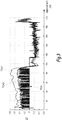
- the harvesting machine performs a half-turn.
- the active suspensions are set to a value other than that of the aisle, so that they return less often abut. TCm is available virtually every moment.
- the graph TCe1 of the estimated value of the charge transfer has also been represented but without implementation of the step of resetting the parameters of the dynamic model. This estimated value is far from the measured value when it is available. It can not therefore be used to evaluate the risk of failover when the measured value is not available.
- the graph TCe2 of the estimated value of the charge transfer has also been represented with implementation of the step of resetting the parameters of the dynamic model.
- This estimated value is very close to the measured value and follows its variations. It can therefore be used as a representative quantity of the risk of failover when the measured value is not available.
- the security signal S is taken into account by other programs executed on the computer 30, such as the program 200 for reducing the risk of failover.
- the execution of the actuation module 210 of the controllable vehicle attitude correction system calculates various instructions intended to be applied to the active suspensions to reduce for example the height of the center of gravity.
- the execution of the vehicle speed regulation module 220 calculates different setpoints for control parameters of the vehicle propulsion and / or steering means.
- the setpoints thus determined are applied at the input of these means in order to reduce, for example, the transverse acceleration of the vehicle.
- the execution of the program 200 provides an arbitration leading to a distribution of the reduction of the risk of overturning between the actuation of the attitude correction system and that of the propulsion and / or steering means.
Landscapes
- Engineering & Computer Science (AREA)
- Mechanical Engineering (AREA)
- Vehicle Body Suspensions (AREA)
- Control Of Driving Devices And Active Controlling Of Vehicle (AREA)
- Electric Propulsion And Braking For Vehicles (AREA)
Claims (15)
- Verfahren zur Verringerung der Gefahr des Kippens eines motorgetriebenen Fahrzeugs (10), das ein steuerbares Aufhängungssystem (24 - 27) aufweist, dadurch gekennzeichnet, dass es umfasst:- einen ersten Schritt des Berechnens einer gemessenen Größe (TCm) als aktuellen Wert (TC) einer Lastübertragung aus einer Mehrzahl von Signalen, die von den Sensoren (28, 29) des steuerbaren Aufhängungssystems geliefert werden;- einen zweiten Schritt des Berechnens einer geschätzten Größe (TCe) aus Signalen, die von an dem Fahrzeug (10) platzierten kinematischen Sensoren geliefert werden, und einem dynamischen Modell (M) des Fahrzeugs, wobei die geschätzte Größe als aktueller Wert der Lastübertragung genommen wird, wenn die gemessene Größe nicht verfügbar ist;- einen Schritt der Bewertung der Gefahr des Kippens aus dem aktuellen Wert (TC) der Lastübertragung und im Fall einer erhöhten Gefahr des Kippens,- einen Schritt des Abgebens eines Sicherheitssignals (S).
- Verfahren nach Anspruch 1, bei dem, wenn die gemessene Größe (TCm) verfügbar ist, das Verfahren einen Schritt der Neueinstellung mindestens eines Parameters (HG) des dynamischen Modells (M) des Fahrzeugs, das in dem zweiten Schritt des Berechnens verwendet wird, aufweist, wobei der Schritt der Neueinstellung darin besteht:- eine Abweichung zwischen der gemessenen Größe (TCm) und der geschätzten Größe (TCe) auszuwerten; und wenn die Abweichung größer ist als ein Schwellenwert (e0),- ein Gesetz der zeitlichen Entwicklung des Parameters zu erarbeiten, wobei das Gesetz die Abweichung zu verringern versucht; und wenn die gemessene Größe (TCm) verfügbar ist,- bei jeder Iteration des zweiten Berechnungsschritts den Wert des Parameters des dynamischen Modells des Fahrzeugs zu modifizieren, indem das Variationsgesetz verwendet wird.
- Verfahren nach Anspruch 2, bei dem der mindestens eine Parameter des dynamischen Modells (M) des Fahrzeugs (10) die Masse (G) oder die Höhe (H) des Gravitätszentrums ist.
- Verfahren nach Anspruch 3, bei dem das Gesetz der zeitlichen Entwicklung für die Höhe (H) des Gravitationszentrums gegeben ist durch eine Beziehung des Typs:


- Verfahren nach Anspruch 4, bei dem das dynamische Modell (M) des Fahrzeugs (10) zwei Parameter, nämlich die Masse (G) und die Höhe des Gravitationszentrums (H) aufweist und das Verfahren einen Schritt der Gewichtung der Gesetze der zeitlichen Entwicklung jedes dieser zwei Parameter mittels eines Koeffizienten, der aus einer Berechnung der Wahrscheinlichkeit des Grundes der Notwendigkeit der Neueinstellung resultiert, aufweist.
- Verfahren nach einem beliebigen der vorhergehenden Ansprüche, bei dem das steuerbare Aufhängungssystem aktive Aufhängungen aufweist und die gemessene Größe (TCm) aus den Signalen berechnet wird, die für eine von jeder der aktiven Aufhängungen (24 - 27) erzeugten Kraft repräsentativ sind.
- Verfahren nach einem beliebigen der vorhergehenden Ansprüche, bei dem die geschätzte Größe (TCe) aus den folgenden Signalen berechnet wird:- einer von einem Dopplerradar (50) gelieferten Längsgeschwindigkeit;- einem Längsneigungswinkel und einem Querneigungswinkel des Fahrzeugs, die von zwei Neigungssensoren (52, 54) geliefert werden;- einer Momentandrehgeschwindigkeit in Bezug auf eine vertikale Achse, die von einem Trägheitssystem (56) geliefert wird; und- einem Einschlagwinkel für jedes Rad, der von einem Winkelsensor (58) des Rades geliefert wird.
- Verfahren nach einem beliebigen der vorhergehenden Ansprüche, bei dem der Schritt der Neueinstellung indirekt die Schätzung der momentanen Masse (G(t)) des Fahrzeugs gestattet.
- Verfahren nach einem beliebigen der vorhergehenden Ansprüche, bei dem das Sicherheitssignal (S) in einem Schritt der Betätigung eines steuerbaren Systems zur Niveauregulierung berücksichtigt wird, um das Kippen des Fahrzeugs zu vermeiden.
- Verfahren nach einem beliebigen der vorhergehenden Ansprüche, bei dem das Sicherheitssignal (S) bei einem Schritt der Einstellung der Antriebsmittel und/oder der Richtungsmittel des Fahrzeugs berücksichtigt wird, um das Kippen des Fahrzeugs zu vermeiden.
- Informationsaufzeichnungsträger, dadurch gekennzeichnet, dass er Befehle für die Ausführung eines Verfahrens zur Verringerung der Gefahr des Kippens eines motorgetriebenen Fahrzeugs, das ein steuerbares Aufhängungssystem aufweist, nach einem beliebigen der Ansprüche 1 bis 10 aufweist, wenn die Befehle durch einen elektronischen Rechner (30) ausgeführt werden.
- System zur Verringerung der Gefahr des Kippens eines ein steuerbares Aufhängungssystem (24-27) aufweisenden, motorbetriebenen Fahrzeugs (10), das einen mitgeführten Rechner (30) aufweist, dadurch gekennzeichnet, dass der mitgeführte Rechner programmiert ist, um ein Verfahren nach einem beliebigen der Ansprüche 1 bis 10 auszuführen.
- System nach Anspruch 12, umfassend:- ein Dopplerradar (50), das geeignet ist, eine Längsgeschwindigkeit zu liefern;- zwei Neigungssensoren (52, 54), die geeignet sind, einen Längsneigungswinkel und einen Querneigungswinkel des Fahrzeugs zu liefern;- ein Trägheitssystem (56), das geeignet ist, eine momentane Drehgeschwindigkeit in Bezug auf eine vertikale Achse zu liefern; und- für jedes Rad einen Radsensor (58), der geeignet ist, einen Einschlagwinkel zu liefern.
- Motorbetriebenes Fahrzeug, das ein steuerbares Aufhängungssystem aufweist, dadurch gekennzeichnet, dass es ein System zur Verringerung der Gefahr des Kippens nach einem beliebigen der Ansprüche 12 und 13 mitführt.
- Fahrzeug nach Anspruch 14, bei dem das Sicherheitssignal (S), das am Ausgang des Systems geliefert wird, von einem Modul (210) der Betätigung eines steuerbaren Aufhängungssystems und/oder einem Modul (220) zur Einstellung von Antriebsmitteln und/oder Richtungsmitteln des Fahrzeugs berücksichtigt wird, um das Kippen des Fahrzeugs zu vermeiden.
Priority Applications (1)
| Application Number | Priority Date | Filing Date | Title |
|---|---|---|---|
| PL14713088T PL2978617T3 (pl) | 2013-03-26 | 2014-03-26 | Sposób ograniczenia ryzyka wywrócenia pojazdu silnikowego wyposażonego w sterowany układ zawieszenia |
Applications Claiming Priority (2)
| Application Number | Priority Date | Filing Date | Title |
|---|---|---|---|
| FR1352736A FR3003834B1 (fr) | 2013-03-26 | 2013-03-26 | Procede de reduction du risque de basculement d'un vehicule automoteur equipe d'un systeme de suspension pilotable |
| PCT/EP2014/056011 WO2014154724A1 (fr) | 2013-03-26 | 2014-03-26 | Procédé de réduction du risque de basculement d'un véhicule automoteur équipé d'un système de suspension pilotable |
Publications (2)
| Publication Number | Publication Date |
|---|---|
| EP2978617A1 EP2978617A1 (de) | 2016-02-03 |
| EP2978617B1 true EP2978617B1 (de) | 2017-08-09 |
Family
ID=48856789
Family Applications (1)
| Application Number | Title | Priority Date | Filing Date |
|---|---|---|---|
| EP14713088.4A Active EP2978617B1 (de) | 2013-03-26 | 2014-03-26 | Verfahren zur reduzierung der umkippgefahr eines kraftfahrzeugs mit einem steuerbaren aufhängungssystem |
Country Status (15)
| Country | Link |
|---|---|
| US (1) | US9849747B2 (de) |
| EP (1) | EP2978617B1 (de) |
| JP (1) | JP6426698B2 (de) |
| KR (1) | KR20160008527A (de) |
| CN (1) | CN105339196B (de) |
| AU (1) | AU2014243067B2 (de) |
| BR (1) | BR112015024769A2 (de) |
| CA (1) | CA2907607A1 (de) |
| DK (1) | DK2978617T3 (de) |
| ES (1) | ES2646940T3 (de) |
| FR (1) | FR3003834B1 (de) |
| NO (1) | NO2978617T3 (de) |
| PL (1) | PL2978617T3 (de) |
| WO (1) | WO2014154724A1 (de) |
| ZA (1) | ZA201507232B (de) |
Families Citing this family (5)
| Publication number | Priority date | Publication date | Assignee | Title |
|---|---|---|---|---|
| CN110606079B (zh) * | 2019-09-18 | 2020-11-17 | 北京理工大学 | 一种分层控制的车辆防侧翻方法及多轴分布式驱动车辆 |
| GB2601347B (en) * | 2020-11-27 | 2023-05-24 | Jaguar Land Rover Ltd | Vehicle ramp angle control |
| US11897506B1 (en) | 2021-03-29 | 2024-02-13 | Zoox, Inc. | Vehicle ride dynamics active comfort tuning system |
| US11780466B1 (en) * | 2021-03-29 | 2023-10-10 | Zoox, Inc. | Vehicle fleet remote ride comfort tuning management system |
| BR102022012824A2 (pt) * | 2022-06-27 | 2024-01-09 | CNH Industrial Brasil Ltda. | Método e sistema para monitorar a estabilidade de uma colheitadeira agrícola e colheitadeira agrícola |
Family Cites Families (16)
| Publication number | Priority date | Publication date | Assignee | Title |
|---|---|---|---|---|
| JPS6092145A (ja) * | 1983-10-25 | 1985-05-23 | Kyokuto Kaihatsu Kogyo Co Ltd | アウトリガを有する作業車の車体水平設定装置 |
| US4927173A (en) * | 1987-12-04 | 1990-05-22 | Clifton Jr Raymond E | Apparatus for preventing truck roll over in the event of failure of its suspension system |
| JPH03153411A (ja) * | 1989-11-06 | 1991-07-01 | Mazda Motor Corp | サスペンションとステアリングの協調制御装置 |
| DE4035784A1 (de) * | 1989-12-01 | 1991-06-06 | Continental Ag | Luftfederung, mit einem luftfederbalg, mit integriertem hoehensensor |
| US5825284A (en) * | 1996-12-10 | 1998-10-20 | Rollover Operations, Llc | System and method for the detection of vehicle rollover conditions |
| JP2001133391A (ja) * | 1999-11-08 | 2001-05-18 | Nissan Motor Co Ltd | 路面摩擦係数推定装置 |
| US6356188B1 (en) * | 2000-09-25 | 2002-03-12 | Ford Global Technologies, Inc. | Wheel lift identification for an automotive vehicle |
| WO2004009383A1 (fr) * | 2002-07-22 | 2004-01-29 | Societe De Technologie Michelin | Dispositif de suspension d'une roue de vehicule |
| JP4848027B2 (ja) * | 2004-01-30 | 2011-12-28 | 日立オートモティブシステムズ株式会社 | 車両制御装置 |
| JP4506522B2 (ja) * | 2005-03-16 | 2010-07-21 | トヨタ自動車株式会社 | サスペンションシステム |
| JP4681414B2 (ja) * | 2005-09-28 | 2011-05-11 | アルパイン株式会社 | 車速検出装置及びナビゲーション装置 |
| US7788007B2 (en) * | 2006-01-12 | 2010-08-31 | Gm Global Technology Operations, Inc. | Roll stability indicator for vehicle rollover control |
| GB0623802D0 (en) * | 2006-11-29 | 2007-01-10 | Brown Duncan | An arrangement of interconnected devices or system to indicate loading state or overload of the axles on a vehicle |
| EP2017150A1 (de) * | 2007-06-27 | 2009-01-21 | Nederlandse Organisatie voor toegepast- natuurwetenschappelijk onderzoek TNO | System und Verfahren zum Melden der Überschlagneigung |
| US20090177346A1 (en) * | 2007-12-19 | 2009-07-09 | Hac Aleksander B | Dynamic estimation of vehicle inertial parameters and tire forces from tire sensors |
| GR1006455B (el) * | 2008-06-25 | 2009-06-22 | Αθανασιου Δημητριος Χατζηκακιδης | Παραμετρικο συστημα πλαισιου για οχηματα σχηματιζομενο απο τεσσερα στοιχεια αναρτησεως με εγκαρσια ραβδο στρεψεως και ομοαξονικο συστημα αποσβεστηρα μεσα σε φατνωμα που επιτρεπει την αποθηκευση κεντρικα βαρεων στοιχειων (οπως μπαταριες) |
-
2013
- 2013-03-26 FR FR1352736A patent/FR3003834B1/fr not_active Expired - Fee Related
-
2014
- 2014-03-26 DK DK14713088.4T patent/DK2978617T3/da active
- 2014-03-26 BR BR112015024769A patent/BR112015024769A2/pt not_active Application Discontinuation
- 2014-03-26 WO PCT/EP2014/056011 patent/WO2014154724A1/fr not_active Ceased
- 2014-03-26 KR KR1020157030677A patent/KR20160008527A/ko not_active Ceased
- 2014-03-26 JP JP2016504646A patent/JP6426698B2/ja not_active Expired - Fee Related
- 2014-03-26 PL PL14713088T patent/PL2978617T3/pl unknown
- 2014-03-26 NO NO14713088A patent/NO2978617T3/no unknown
- 2014-03-26 ES ES14713088.4T patent/ES2646940T3/es active Active
- 2014-03-26 EP EP14713088.4A patent/EP2978617B1/de active Active
- 2014-03-26 AU AU2014243067A patent/AU2014243067B2/en not_active Ceased
- 2014-03-26 CA CA2907607A patent/CA2907607A1/fr not_active Abandoned
- 2014-03-26 US US14/780,097 patent/US9849747B2/en not_active Expired - Fee Related
- 2014-03-26 CN CN201480023449.8A patent/CN105339196B/zh not_active Expired - Fee Related
-
2015
- 2015-09-30 ZA ZA2015/07232A patent/ZA201507232B/en unknown
Non-Patent Citations (1)
| Title |
|---|
| None * |
Also Published As
| Publication number | Publication date |
|---|---|
| DK2978617T3 (da) | 2017-11-13 |
| CN105339196B (zh) | 2018-04-06 |
| WO2014154724A1 (fr) | 2014-10-02 |
| KR20160008527A (ko) | 2016-01-22 |
| AU2014243067B2 (en) | 2017-12-14 |
| CA2907607A1 (fr) | 2014-10-02 |
| BR112015024769A2 (pt) | 2017-07-18 |
| AU2014243067A1 (en) | 2015-11-12 |
| PL2978617T3 (pl) | 2018-01-31 |
| US9849747B2 (en) | 2017-12-26 |
| CN105339196A (zh) | 2016-02-17 |
| FR3003834B1 (fr) | 2015-04-24 |
| ES2646940T3 (es) | 2017-12-18 |
| FR3003834A1 (fr) | 2014-10-03 |
| ZA201507232B (en) | 2017-09-27 |
| NO2978617T3 (de) | 2018-01-06 |
| EP2978617A1 (de) | 2016-02-03 |
| JP2016519625A (ja) | 2016-07-07 |
| JP6426698B2 (ja) | 2018-11-21 |
| US20160046167A1 (en) | 2016-02-18 |
Similar Documents
| Publication | Publication Date | Title |
|---|---|---|
| EP2978617A1 (de) | Verfahren zur reduzierung der umkippgefahr eines kraftfahrzeugs mit einem steuerbaren aufhängungssystem | |
| EP2895826B1 (de) | Vorrichtung und verfahren zur schätzung der ladung eines kraftfahrzeugs | |
| WO2020201141A1 (fr) | Module anticipateur, dispositif de contrôle en temps réel de trajectoire et procédé associés | |
| WO2021079004A1 (fr) | Procédé de commande d'un véhicule roulant en condition d'adhérence précaire | |
| FR3054497A1 (fr) | Dispositif de regulation de vitesse | |
| EP2487057A1 (de) | Vereinfachtes Verfahren zur Regelung von Stoßdämpfern | |
| RU2702476C1 (ru) | Способ предотвращения опрокидывания автомобиля | |
| EP1621431A1 (de) | Verfahren und Vorrichtung zur Bremskraftverteilung vorne/hinten für ein Kraftfahrzeug | |
| FR3092914A1 (fr) | Procédé de détermination de la trajectoire d'un véhicule comprenant quatre roues directrices | |
| EP1907260B1 (de) | Verfahren zur steuerung der lenkausrichtung eines fahrzeugs | |
| FR2904958A1 (fr) | Dispositif d'anti-patinage ameliore des roues motrices d'un vehicule et procede pour sa mise en oeuvre. | |
| FR2912363A1 (fr) | Systeme et procede de determination de l'angle de devers d'un vehicule a partir des efforts exerces sur les roues | |
| EP3080565B1 (de) | Vorrichtung und verfahren zur schätzung der gesamtmasse eines kraftfahrzeugs mit fahrzeuginterner kalibrierung von aufhängungsverlagerungssensoren | |
| WO2007003861A2 (fr) | Procédé et système anti-roulis d'un véhicule et véhicule correspondant | |
| WO2008062115A1 (fr) | Procede et dispositif de rejet de perturbations avec un systeme de braquage d'un vehicule automobile | |
| EP2027004B1 (de) | Verfahren und steuersystem für ein fahrzeuglenkrad | |
| FR2945122A1 (fr) | Procede et dispositif d'evaluation de l'usure d'un pneu | |
| FR2930923A1 (fr) | Procede de controle d'un systeme de pilotage du comportement dynamique d'une caisse de vehicule automobile | |
| WO2013144469A1 (fr) | Procede d'estimation de la resistance au roulement de roues equipant un train d'un vehicule | |
| EP1541435A1 (de) | Verfahren zur Verzögerungsregelung eines Fahrzeugs unter Begrenzung unsymmetrisch verteilter Bremsmomente | |
| FR3157335A1 (fr) | Procédé de commande d’un véhicule automobile à quatre roues directrices, comportant la commande d’un actionneur de braquage des roues arrière par un signal à action directe | |
| WO2021079003A1 (fr) | Procede de commande d'un vehicule roulant en condition d'adherence precaire | |
| FR2841200A1 (fr) | Procede et dispositif pour le freinage en courbe d'un vehicule atomobile | |
| WO2008107613A1 (fr) | Systeme et procede de commande en boucle ouverte d'un systeme antiroulis actif par typage de la vitesse en lacet d'un vehicule base sur un modele non lineaire deux roues | |
| FR3026680A1 (fr) | Systeme de pilotage d'amortisseurs |
Legal Events
| Date | Code | Title | Description |
|---|---|---|---|
| PUAI | Public reference made under article 153(3) epc to a published international application that has entered the european phase |
Free format text: ORIGINAL CODE: 0009012 |
|
| 17P | Request for examination filed |
Effective date: 20151001 |
|
| AK | Designated contracting states |
Kind code of ref document: A1 Designated state(s): AL AT BE BG CH CY CZ DE DK EE ES FI FR GB GR HR HU IE IS IT LI LT LU LV MC MK MT NL NO PL PT RO RS SE SI SK SM TR |
|
| AX | Request for extension of the european patent |
Extension state: BA ME |
|
| RIN1 | Information on inventor provided before grant (corrected) |
Inventor name: LENAIN, ROLAND Inventor name: RICHIER, MATHIEU Inventor name: DIEUMET, DENIS Inventor name: THUILOT, BENOIT Inventor name: BOUTON, NICOLAS |
|
| DAX | Request for extension of the european patent (deleted) | ||
| GRAP | Despatch of communication of intention to grant a patent |
Free format text: ORIGINAL CODE: EPIDOSNIGR1 |
|
| INTG | Intention to grant announced |
Effective date: 20170309 |
|
| GRAS | Grant fee paid |
Free format text: ORIGINAL CODE: EPIDOSNIGR3 |
|
| GRAA | (expected) grant |
Free format text: ORIGINAL CODE: 0009210 |
|
| AK | Designated contracting states |
Kind code of ref document: B1 Designated state(s): AL AT BE BG CH CY CZ DE DK EE ES FI FR GB GR HR HU IE IS IT LI LT LU LV MC MK MT NL NO PL PT RO RS SE SI SK SM TR |
|
| REG | Reference to a national code |
Ref country code: GB Ref legal event code: FG4D Free format text: NOT ENGLISH |
|
| REG | Reference to a national code |
Ref country code: CH Ref legal event code: EP Ref country code: AT Ref legal event code: REF Ref document number: 916403 Country of ref document: AT Kind code of ref document: T Effective date: 20170815 |
|
| REG | Reference to a national code |
Ref country code: IE Ref legal event code: FG4D Free format text: LANGUAGE OF EP DOCUMENT: FRENCH |
|
| REG | Reference to a national code |
Ref country code: DE Ref legal event code: R096 Ref document number: 602014012834 Country of ref document: DE |
|
| RAP2 | Party data changed (patent owner data changed or rights of a patent transferred) |
Owner name: UNIVERSITE CLERMONT AUVERGNE Owner name: INSTITUT NATIONAL DE RECHERCHE EN SCIENCES ET TECH |
|
| REG | Reference to a national code |
Ref country code: DK Ref legal event code: T3 Effective date: 20171107 |
|
| REG | Reference to a national code |
Ref country code: CH Ref legal event code: NV Representative=s name: ARNOLD AND SIEDSMA AG, CH |
|
| REG | Reference to a national code |
Ref country code: ES Ref legal event code: FG2A Ref document number: 2646940 Country of ref document: ES Kind code of ref document: T3 Effective date: 20171218 |
|
| REG | Reference to a national code |
Ref country code: NL Ref legal event code: FP |
|
| REG | Reference to a national code |
Ref country code: LT Ref legal event code: MG4D |
|
| REG | Reference to a national code |
Ref country code: NL Ref legal event code: PD Owner name: INSTITUT NATIONAL DE RECHERCHE EN SCIENCES ET TEC Free format text: DETAILS ASSIGNMENT: CHANGE OF OWNER(S), ASSIGNMENT; FORMER OWNER NAME: UNIVERSITE BLAISE PASCAL CLERMONT II Effective date: 20171107 |
|
| REG | Reference to a national code |
Ref country code: FR Ref legal event code: PLFP Year of fee payment: 5 |
|
| REG | Reference to a national code |
Ref country code: NO Ref legal event code: T2 Effective date: 20170809 |
|
| PG25 | Lapsed in a contracting state [announced via postgrant information from national office to epo] |
Ref country code: LT Free format text: LAPSE BECAUSE OF FAILURE TO SUBMIT A TRANSLATION OF THE DESCRIPTION OR TO PAY THE FEE WITHIN THE PRESCRIBED TIME-LIMIT Effective date: 20170809 Ref country code: SE Free format text: LAPSE BECAUSE OF FAILURE TO SUBMIT A TRANSLATION OF THE DESCRIPTION OR TO PAY THE FEE WITHIN THE PRESCRIBED TIME-LIMIT Effective date: 20170809 Ref country code: FI Free format text: LAPSE BECAUSE OF FAILURE TO SUBMIT A TRANSLATION OF THE DESCRIPTION OR TO PAY THE FEE WITHIN THE PRESCRIBED TIME-LIMIT Effective date: 20170809 Ref country code: HR Free format text: LAPSE BECAUSE OF FAILURE TO SUBMIT A TRANSLATION OF THE DESCRIPTION OR TO PAY THE FEE WITHIN THE PRESCRIBED TIME-LIMIT Effective date: 20170809 |
|
| REG | Reference to a national code |
Ref country code: BE Ref legal event code: PD Owner name: UNIVERSITE CLERMONT AUVERGNE; FR Free format text: DETAILS ASSIGNMENT: CHANGE OF OWNER(S), AFFECTATION / CESSION; FORMER OWNER NAME: INSTITUT NATIONAL DE RECHERCHE EN SCIENCES ET TECHNOLOGIES POUR L'ENVIRONNEMENT ET L'AGRICULTURE (IRSTEA) Effective date: 20171026 |
|
| PG25 | Lapsed in a contracting state [announced via postgrant information from national office to epo] |
Ref country code: RS Free format text: LAPSE BECAUSE OF FAILURE TO SUBMIT A TRANSLATION OF THE DESCRIPTION OR TO PAY THE FEE WITHIN THE PRESCRIBED TIME-LIMIT Effective date: 20170809 Ref country code: GR Free format text: LAPSE BECAUSE OF FAILURE TO SUBMIT A TRANSLATION OF THE DESCRIPTION OR TO PAY THE FEE WITHIN THE PRESCRIBED TIME-LIMIT Effective date: 20171110 Ref country code: LV Free format text: LAPSE BECAUSE OF FAILURE TO SUBMIT A TRANSLATION OF THE DESCRIPTION OR TO PAY THE FEE WITHIN THE PRESCRIBED TIME-LIMIT Effective date: 20170809 Ref country code: IS Free format text: LAPSE BECAUSE OF FAILURE TO SUBMIT A TRANSLATION OF THE DESCRIPTION OR TO PAY THE FEE WITHIN THE PRESCRIBED TIME-LIMIT Effective date: 20171209 Ref country code: BG Free format text: LAPSE BECAUSE OF FAILURE TO SUBMIT A TRANSLATION OF THE DESCRIPTION OR TO PAY THE FEE WITHIN THE PRESCRIBED TIME-LIMIT Effective date: 20171109 |
|
| PG25 | Lapsed in a contracting state [announced via postgrant information from national office to epo] |
Ref country code: CZ Free format text: LAPSE BECAUSE OF FAILURE TO SUBMIT A TRANSLATION OF THE DESCRIPTION OR TO PAY THE FEE WITHIN THE PRESCRIBED TIME-LIMIT Effective date: 20170809 Ref country code: RO Free format text: LAPSE BECAUSE OF FAILURE TO SUBMIT A TRANSLATION OF THE DESCRIPTION OR TO PAY THE FEE WITHIN THE PRESCRIBED TIME-LIMIT Effective date: 20170809 |
|
| REG | Reference to a national code |
Ref country code: DE Ref legal event code: R097 Ref document number: 602014012834 Country of ref document: DE |
|
| PG25 | Lapsed in a contracting state [announced via postgrant information from national office to epo] |
Ref country code: IT Free format text: LAPSE BECAUSE OF FAILURE TO SUBMIT A TRANSLATION OF THE DESCRIPTION OR TO PAY THE FEE WITHIN THE PRESCRIBED TIME-LIMIT Effective date: 20170809 Ref country code: SM Free format text: LAPSE BECAUSE OF FAILURE TO SUBMIT A TRANSLATION OF THE DESCRIPTION OR TO PAY THE FEE WITHIN THE PRESCRIBED TIME-LIMIT Effective date: 20170809 Ref country code: SK Free format text: LAPSE BECAUSE OF FAILURE TO SUBMIT A TRANSLATION OF THE DESCRIPTION OR TO PAY THE FEE WITHIN THE PRESCRIBED TIME-LIMIT Effective date: 20170809 Ref country code: EE Free format text: LAPSE BECAUSE OF FAILURE TO SUBMIT A TRANSLATION OF THE DESCRIPTION OR TO PAY THE FEE WITHIN THE PRESCRIBED TIME-LIMIT Effective date: 20170809 |
|
| PLBE | No opposition filed within time limit |
Free format text: ORIGINAL CODE: 0009261 |
|
| STAA | Information on the status of an ep patent application or granted ep patent |
Free format text: STATUS: NO OPPOSITION FILED WITHIN TIME LIMIT |
|
| 26N | No opposition filed |
Effective date: 20180511 |
|
| PG25 | Lapsed in a contracting state [announced via postgrant information from national office to epo] |
Ref country code: SI Free format text: LAPSE BECAUSE OF FAILURE TO SUBMIT A TRANSLATION OF THE DESCRIPTION OR TO PAY THE FEE WITHIN THE PRESCRIBED TIME-LIMIT Effective date: 20170809 |
|
| PG25 | Lapsed in a contracting state [announced via postgrant information from national office to epo] |
Ref country code: MT Free format text: LAPSE BECAUSE OF FAILURE TO SUBMIT A TRANSLATION OF THE DESCRIPTION OR TO PAY THE FEE WITHIN THE PRESCRIBED TIME-LIMIT Effective date: 20170809 |
|
| PG25 | Lapsed in a contracting state [announced via postgrant information from national office to epo] |
Ref country code: MC Free format text: LAPSE BECAUSE OF FAILURE TO SUBMIT A TRANSLATION OF THE DESCRIPTION OR TO PAY THE FEE WITHIN THE PRESCRIBED TIME-LIMIT Effective date: 20170809 |
|
| REG | Reference to a national code |
Ref country code: IE Ref legal event code: MM4A |
|
| PG25 | Lapsed in a contracting state [announced via postgrant information from national office to epo] |
Ref country code: IE Free format text: LAPSE BECAUSE OF NON-PAYMENT OF DUE FEES Effective date: 20180326 |
|
| PGFP | Annual fee paid to national office [announced via postgrant information from national office to epo] |
Ref country code: LU Payment date: 20190214 Year of fee payment: 6 Ref country code: NL Payment date: 20190212 Year of fee payment: 6 |
|
| PGFP | Annual fee paid to national office [announced via postgrant information from national office to epo] |
Ref country code: CH Payment date: 20190320 Year of fee payment: 6 Ref country code: GB Payment date: 20190320 Year of fee payment: 6 Ref country code: DE Payment date: 20190312 Year of fee payment: 6 Ref country code: NO Payment date: 20190220 Year of fee payment: 6 Ref country code: PL Payment date: 20190215 Year of fee payment: 6 |
|
| PGFP | Annual fee paid to national office [announced via postgrant information from national office to epo] |
Ref country code: BE Payment date: 20190325 Year of fee payment: 6 Ref country code: AT Payment date: 20190219 Year of fee payment: 6 Ref country code: DK Payment date: 20190225 Year of fee payment: 6 |
|
| PGFP | Annual fee paid to national office [announced via postgrant information from national office to epo] |
Ref country code: ES Payment date: 20190410 Year of fee payment: 6 |
|
| PG25 | Lapsed in a contracting state [announced via postgrant information from national office to epo] |
Ref country code: TR Free format text: LAPSE BECAUSE OF FAILURE TO SUBMIT A TRANSLATION OF THE DESCRIPTION OR TO PAY THE FEE WITHIN THE PRESCRIBED TIME-LIMIT Effective date: 20170809 |
|
| PG25 | Lapsed in a contracting state [announced via postgrant information from national office to epo] |
Ref country code: PT Free format text: LAPSE BECAUSE OF FAILURE TO SUBMIT A TRANSLATION OF THE DESCRIPTION OR TO PAY THE FEE WITHIN THE PRESCRIBED TIME-LIMIT Effective date: 20170809 |
|
| PG25 | Lapsed in a contracting state [announced via postgrant information from national office to epo] |
Ref country code: HU Free format text: LAPSE BECAUSE OF FAILURE TO SUBMIT A TRANSLATION OF THE DESCRIPTION OR TO PAY THE FEE WITHIN THE PRESCRIBED TIME-LIMIT; INVALID AB INITIO Effective date: 20140326 Ref country code: MK Free format text: LAPSE BECAUSE OF NON-PAYMENT OF DUE FEES Effective date: 20170809 Ref country code: CY Free format text: LAPSE BECAUSE OF FAILURE TO SUBMIT A TRANSLATION OF THE DESCRIPTION OR TO PAY THE FEE WITHIN THE PRESCRIBED TIME-LIMIT Effective date: 20170809 |
|
| PG25 | Lapsed in a contracting state [announced via postgrant information from national office to epo] |
Ref country code: AL Free format text: LAPSE BECAUSE OF FAILURE TO SUBMIT A TRANSLATION OF THE DESCRIPTION OR TO PAY THE FEE WITHIN THE PRESCRIBED TIME-LIMIT Effective date: 20170809 |
|
| REG | Reference to a national code |
Ref country code: DE Ref legal event code: R119 Ref document number: 602014012834 Country of ref document: DE |
|
| REG | Reference to a national code |
Ref country code: NO Ref legal event code: MMEP |
|
| REG | Reference to a national code |
Ref country code: CH Ref legal event code: PL |
|
| REG | Reference to a national code |
Ref country code: DK Ref legal event code: EBP Effective date: 20200331 |
|
| REG | Reference to a national code |
Ref country code: NL Ref legal event code: MM Effective date: 20200401 |
|
| REG | Reference to a national code |
Ref country code: AT Ref legal event code: MM01 Ref document number: 916403 Country of ref document: AT Kind code of ref document: T Effective date: 20200326 |
|
| REG | Reference to a national code |
Ref country code: BE Ref legal event code: MM Effective date: 20200331 |
|
| PG25 | Lapsed in a contracting state [announced via postgrant information from national office to epo] |
Ref country code: LU Free format text: LAPSE BECAUSE OF NON-PAYMENT OF DUE FEES Effective date: 20200326 Ref country code: NL Free format text: LAPSE BECAUSE OF NON-PAYMENT OF DUE FEES Effective date: 20200401 |
|
| PG25 | Lapsed in a contracting state [announced via postgrant information from national office to epo] |
Ref country code: CH Free format text: LAPSE BECAUSE OF NON-PAYMENT OF DUE FEES Effective date: 20200331 Ref country code: DE Free format text: LAPSE BECAUSE OF NON-PAYMENT OF DUE FEES Effective date: 20201001 Ref country code: NO Free format text: LAPSE BECAUSE OF NON-PAYMENT OF DUE FEES Effective date: 20200331 Ref country code: LI Free format text: LAPSE BECAUSE OF NON-PAYMENT OF DUE FEES Effective date: 20200331 Ref country code: AT Free format text: LAPSE BECAUSE OF NON-PAYMENT OF DUE FEES Effective date: 20200326 |
|
| PG25 | Lapsed in a contracting state [announced via postgrant information from national office to epo] |
Ref country code: BE Free format text: LAPSE BECAUSE OF NON-PAYMENT OF DUE FEES Effective date: 20200331 |
|
| GBPC | Gb: european patent ceased through non-payment of renewal fee |
Effective date: 20200326 |
|
| PG25 | Lapsed in a contracting state [announced via postgrant information from national office to epo] |
Ref country code: GB Free format text: LAPSE BECAUSE OF NON-PAYMENT OF DUE FEES Effective date: 20200326 Ref country code: DK Free format text: LAPSE BECAUSE OF NON-PAYMENT OF DUE FEES Effective date: 20200331 |
|
| REG | Reference to a national code |
Ref country code: AT Ref legal event code: UEP Ref document number: 916403 Country of ref document: AT Kind code of ref document: T Effective date: 20170809 |
|
| REG | Reference to a national code |
Ref country code: ES Ref legal event code: FD2A Effective date: 20210812 |
|
| PG25 | Lapsed in a contracting state [announced via postgrant information from national office to epo] |
Ref country code: ES Free format text: LAPSE BECAUSE OF NON-PAYMENT OF DUE FEES Effective date: 20200327 |
|
| PG25 | Lapsed in a contracting state [announced via postgrant information from national office to epo] |
Ref country code: PL Free format text: LAPSE BECAUSE OF NON-PAYMENT OF DUE FEES Effective date: 20200326 |
|
| PGFP | Annual fee paid to national office [announced via postgrant information from national office to epo] |
Ref country code: FR Payment date: 20260324 Year of fee payment: 13 |