EP2978556B1 - Welded portion inspection apparatus and inspection method thereof, with inspection in different zones of the molten pool - Google Patents
Welded portion inspection apparatus and inspection method thereof, with inspection in different zones of the molten pool Download PDFInfo
- Publication number
- EP2978556B1 EP2978556B1 EP14720691.6A EP14720691A EP2978556B1 EP 2978556 B1 EP2978556 B1 EP 2978556B1 EP 14720691 A EP14720691 A EP 14720691A EP 2978556 B1 EP2978556 B1 EP 2978556B1
- Authority
- EP
- European Patent Office
- Prior art keywords
- welding
- workpieces
- inspection
- laser beam
- welded portion
- Prior art date
- Legal status (The legal status is an assumption and is not a legal conclusion. Google has not performed a legal analysis and makes no representation as to the accuracy of the status listed.)
- Active
Links
- 238000007689 inspection Methods 0.000 title claims description 185
- 238000000034 method Methods 0.000 title claims description 19
- 238000003466 welding Methods 0.000 claims description 204
- 230000005855 radiation Effects 0.000 claims description 51
- 230000008020 evaporation Effects 0.000 claims description 8
- 238000001704 evaporation Methods 0.000 claims description 8
- 230000008018 melting Effects 0.000 claims description 8
- 238000002844 melting Methods 0.000 claims description 8
- 230000000737 periodic effect Effects 0.000 description 8
- 229910000831 Steel Inorganic materials 0.000 description 7
- 238000006243 chemical reaction Methods 0.000 description 7
- 230000000994 depressogenic effect Effects 0.000 description 7
- 239000010959 steel Substances 0.000 description 7
- 238000012545 processing Methods 0.000 description 6
- 239000011324 bead Substances 0.000 description 4
- 238000010586 diagram Methods 0.000 description 4
- 230000003287 optical effect Effects 0.000 description 4
- 230000007423 decrease Effects 0.000 description 3
- 238000002474 experimental method Methods 0.000 description 3
- 239000007788 liquid Substances 0.000 description 3
- 238000013441 quality evaluation Methods 0.000 description 3
- 238000004519 manufacturing process Methods 0.000 description 2
- 238000000691 measurement method Methods 0.000 description 2
- 239000000470 constituent Substances 0.000 description 1
- 238000013461 design Methods 0.000 description 1
- 238000011156 evaluation Methods 0.000 description 1
- 238000005304 joining Methods 0.000 description 1
- 238000005259 measurement Methods 0.000 description 1
Images


Classifications
-
- B—PERFORMING OPERATIONS; TRANSPORTING
- B23—MACHINE TOOLS; METAL-WORKING NOT OTHERWISE PROVIDED FOR
- B23K—SOLDERING OR UNSOLDERING; WELDING; CLADDING OR PLATING BY SOLDERING OR WELDING; CUTTING BY APPLYING HEAT LOCALLY, e.g. FLAME CUTTING; WORKING BY LASER BEAM
- B23K31/00—Processes relevant to this subclass, specially adapted for particular articles or purposes, but not covered by only one of the preceding main groups
- B23K31/12—Processes relevant to this subclass, specially adapted for particular articles or purposes, but not covered by only one of the preceding main groups relating to investigating the properties, e.g. the weldability, of materials
- B23K31/125—Weld quality monitoring
-
- B—PERFORMING OPERATIONS; TRANSPORTING
- B23—MACHINE TOOLS; METAL-WORKING NOT OTHERWISE PROVIDED FOR
- B23K—SOLDERING OR UNSOLDERING; WELDING; CLADDING OR PLATING BY SOLDERING OR WELDING; CUTTING BY APPLYING HEAT LOCALLY, e.g. FLAME CUTTING; WORKING BY LASER BEAM
- B23K26/00—Working by laser beam, e.g. welding, cutting or boring
- B23K26/02—Positioning or observing the workpiece, e.g. with respect to the point of impact; Aligning, aiming or focusing the laser beam
- B23K26/03—Observing, e.g. monitoring, the workpiece
-
- B—PERFORMING OPERATIONS; TRANSPORTING
- B23—MACHINE TOOLS; METAL-WORKING NOT OTHERWISE PROVIDED FOR
- B23K—SOLDERING OR UNSOLDERING; WELDING; CLADDING OR PLATING BY SOLDERING OR WELDING; CUTTING BY APPLYING HEAT LOCALLY, e.g. FLAME CUTTING; WORKING BY LASER BEAM
- B23K26/00—Working by laser beam, e.g. welding, cutting or boring
- B23K26/20—Bonding
- B23K26/21—Bonding by welding
- B23K26/24—Seam welding
-
- G—PHYSICS
- G01—MEASURING; TESTING
- G01B—MEASURING LENGTH, THICKNESS OR SIMILAR LINEAR DIMENSIONS; MEASURING ANGLES; MEASURING AREAS; MEASURING IRREGULARITIES OF SURFACES OR CONTOURS
- G01B11/00—Measuring arrangements characterised by the use of optical techniques
- G01B11/30—Measuring arrangements characterised by the use of optical techniques for measuring roughness or irregularity of surfaces
-
- B—PERFORMING OPERATIONS; TRANSPORTING
- B23—MACHINE TOOLS; METAL-WORKING NOT OTHERWISE PROVIDED FOR
- B23K—SOLDERING OR UNSOLDERING; WELDING; CLADDING OR PLATING BY SOLDERING OR WELDING; CUTTING BY APPLYING HEAT LOCALLY, e.g. FLAME CUTTING; WORKING BY LASER BEAM
- B23K26/00—Working by laser beam, e.g. welding, cutting or boring
- B23K26/20—Bonding
- B23K26/21—Bonding by welding
- B23K26/22—Spot welding
Definitions
- the present invention relates to a welded portion inspection apparatus and an inspection method thereof, according to the preamble of claims 1 and 6 (see, for example, US6,791,057B1 ), and relates to an inspection apparatus that inspects a welding state of a welded portion formed at the time when a plurality of workpieces is welded by a laser beam, for example, and an inspection method thereof.
- JP 2008-87056 A JP 2008-87056 A
- US Patent No. 6,791,057 US 6,798,057 B1
- European Patent Application Publication No. 2 543 464 EP 2 543 464 A2
- a YAG laser is radiated from a laser torch, for example, and laser reflection light is received by first light receiving output means from a forward-diagonally upward side of a welding proceeding direction. Further, welding light including vapor light (plume) and the laser reflection light is received by second light receiving output means in a direction coaxial to a radiation direction of the laser beam. The laser reflection light and the welding light that are received simultaneously in two predetermined directions are converted into electrical signals according to their respective intensities. This system determines a welding quality based on the signal intensities of the electrical signals or changes thereof.
- the laser reflection light and the welding light are received simultaneously in two predetermined directions different from each other and their respective light receiving signal intensities are compared with a threshold set appropriately.
- weld shrinkage underfill
- unjoined weld in which upper and lower steel sheets are not joined due to an excessively large gap between the steel sheets
- depressed weld in which a bead is depressed similarly due to an excessively large gap between steel sheets
- molten weld in which a bead disappears accidentally due to fluctuation of a thermal balance
- vapor light caused due to melting and evaporation of the workpieces and thermal radiation light emitted from a molten pool of the workpieces change according to a workpiece temperature
- the electrical signals obtained from the received laser reflection light and the welding light and the threshold to determine the quality of the laser beam welding change according to the workpiece temperature. Because of this, in a case where the workpiece temperature largely fluctuates in the laser beam welding, the determination accuracy of the poor welding of the workpieces may further decreases.
- the present invention provides a welded portion inspection apparatus that is able to minutely inspect a welding state of a welded portion of workpieces in remote welding in which welding is performed such that the workpieces are spaced from a laser torch, and an inspection method thereof.
- a first aspect of the invention relates to a welded portion inspection apparatus as defined in claim 1, that inspects a welding state of a welded portion formed at the time when a plurality of workpieces is welded.
- the welded portion inspection apparatus includes: a radiation portion that radiates a welding laser beam along a welding locus set in the workpieces so as to weld the workpieces, or radiates an inspection laser beam along a scanning locus set in a molten pool of the workpieces that are molten by the welding laser beam; a light-receiving portion that receives a returned light beam including at least one of reflection light of the welding laser beam or the inspection laser beam radiated by the radiation portion, the reflection light being reflected from the molten pool of the workpieces, vapor light caused due to melting and evaporation of the workpieces, and thermal radiation light emitted from the molten pool of the workpieces; and an inspection portion that inspects a welding state of a welded portion of the workpieces
- the welding state of the welded portion of the workpieces is inspected based on the intensity of the returned light beam received in the first region inside the molten pool formed in the workpieces which is relatively close to the given point and the intensity of the returned light beam received in the second region inside the molten pool formed in the workpieces which is relatively spaced from the given point.
- the inspection portion inspects the welding state of the welded portion of the workpieces based on a ratio between the intensity of the returned light beam received by the light-receiving portion in the first region and the intensity of the returned light beam received by the light-receiving portion in the second region.
- the welding state of the welded portion of the workpieces is inspected based on the ratio between the intensity of the returned light beam received in the first region and the intensity of the returned light beam received in the second region. Accordingly, even if an electrical signal obtained from the returned light beam received by the light-receiving portion is weak or even if the intensity of the returned light beam received by the light-receiving portion changes according to a change of a workpiece temperature, for example, it is possible to determine the welding state of the welded portion formed in the workpieces, based on substantially uniform criteria, thereby making it possible to more minutely inspect the welding state of the welded portion of the workpieces.
- the inspection portion may inspect the welding state of the welded portion of the workpieces based on an average intensity of the returned light beam received by the light-receiving portion in the first region and an average intensity of the returned light beam received by the light-receiving portion in the second region.
- the welding state of the welded portion of the workpieces is inspected based on the average intensity of the returned light beam received in the first region and the average intensity of the returned light beam received in the second region. Accordingly, even if the intensity of the returned light beam received by the light-receiving portion changes according to a change of a workpiece temperature or periodic vibration of a liquid level of the molten pool, for example, it is possible to determine the welding state of the welded portion formed in the workpieces, based on substantially uniform criteria, thereby making it possible to further more minutely inspect the welding state of the welded portion of the workpieces.
- the average intensity of the returned light beam received by the light-receiving portion in the first region is that intensity of the returned light beam per unit length, per unit area, or per unit time which is obtained by dividing a total sum of intensities of the returned light beam received by the light-receiving portion in the first region, by a length scanned by a laser beam in the first region, an area of the first region, a time during which the laser beam performs scanning in the first region, or the like.
- the average intensity of the returned light beam received by the light-receiving portion in the second region is similarly that intensity of the returned light beam per unit length, per unit area, or per unit time which is obtained by dividing a total sum of intensities of the returned light beam received by the light-receiving portion in the second region, by a length scanned by a laser beam in the second region, an area of the second region, a time during which the laser beam performs scanning in the second region, or the like.
- a second aspect of the invention relates to a welded portion inspection method as defined in claim 6, that inspects a welding state of a welded portion formed at the time when a plurality of workpieces is welded.
- the welded portion inspection method includes radiating a welding laser beam along a welding locus set in the workpieces so as to weld the workpieces, or radiating an inspection laser beam along a scanning locus set in a molten pool of the workpieces that are molten by the welding laser beam; receiving a returned light beam including at least one of reflection light of the welding laser beam or the inspection laser beam which is reflected from the molten pool of the workpieces, vapor light caused due to melting and evaporation of the workpieces, and thermal radiation light emitted from the molten pool of the workpieces; and inspecting a welding state of a welded portion of the workpieces based on an intensity of a returned light beam received in a first region inside the molten pool of the workpieces which is relatively close
- the welding state of the welded portion of the workpieces is inspected based on a ratio between the intensity of the returned light beam received in the first region inside the molten pool formed in the workpieces which is relatively close to the given point and the intensity of the returned light beam received in the second region inside the molten pool formed in the workpieces which is relatively spaced from the given point.
- the first and second aspects of the invention have such a simple configuration that, at the time when a plurality of workpieces is welded, a welding state of a welded portion of the workpieces is inspected based on an intensity of a returned light beam received in the first region inside a molten pool of the workpieces which is relatively close to a given point and an intensity of a returned light beam received in the second region inside the molten pool of the workpieces which is relatively spaced from the given point. Accordingly, even if an electrical signal obtained from the returned light beam is weak or even if the intensity of the returned light beam changes according to a change of a workpiece temperature, it is possible to minutely inspect the welding state of the welded portion of the workpieces.
- Embodiment 1 of the welded portion inspection apparatus of the present invention With reference to FIGS. 1 to 3 .
- FIG. 1 is an overall configuration diagram schematically illustrating an overall configuration of Embodiment 1 of the welded portion inspection apparatus of the present invention.
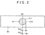
- FIG. 2 is a top view to describe a form of radiation of a welding laser beam from a welding radiation portion of the inspection apparatus as illustrated in FIG. 1
- FIG. 3 is a top view to describe a form of radiation of an inspection laser beam from an inspection radiation portion of the inspection apparatus.
- An inspection apparatus 100 illustrated in FIG. 1 is mainly constituted by a welding radiation portion 1, an inspection radiation portion 5, a light-receiving portion 2, a conversion portion 3, an amplifier 4, an inspection portion 6, and a CRT (Cathode Ray Tube) 7.
- the welding radiation portion 1 radiates a welding laser beam (e.g., a YAG laser having a predetermined laser wavelength) L1 to the two workpieces W1, W2. More specifically, as illustrated in FIG. 2 , the welding radiation portion 1 rotates a focal point F1 of the welding laser beam L1 several times along a generally round-shaped welding locus C11 having a radius R11 set in the workpiece W1, so as to radiate the welding laser beam L1 several times on the welding locus C11.
- a welding laser beam e.g., a YAG laser having a predetermined laser wavelength
- the welding radiation portion 1 moves the focal point F1 of the welding laser beam L1 inside the welding locus C11, and rotates the focal point F1 of the welding laser beam L1 several times along a generally round-shaped welding locus C12 which has a radius R12 that is smaller than the radius R11 and which is coaxial to the welding locus C11, so as to radiate the welding laser beam L1 several times on the welding locus C12.
- a generally round-shaped welded portion is formed in the workpieces W1, W2, thereby joining the workpieces W1, W2 by welding (also referred to as Laser Screw Welding).
- a center C0 of the welding locus C11 or the welding locus C12 is a welding center of the welded portion formed in the workpieces W1, W2.
- a molten pool Y1 where the workpieces W1, W2 are molten is formed on right and left sides of the welding laser beam L1 and behind the welding laser beam L1 in a traveling direction of the welding laser beam L1.
- the welding laser beam L1 is radiated along the generally round-shaped welding loci C1, C2 as described above, a generally round-shaped molten pool Y1 is formed in the workpieces W1, W2.
- the inspection radiation portion 5 radiates an inspection laser beam L5 to the molten pool Y1 in a molten state via an optical system 8 and the light-receiving portion 2. More specifically, as illustrated in FIG. 3 , the inspection radiation portion 5 rotates a focal point F5 of the inspection laser beam L5 several times at a generally constant speed along a generally round-shaped scanning locus C51 having a radius R51 set inside an outer edge of the molten pool Y1, so as to radiate the inspection laser beam L5 several times on the scanning locus C51.
- the inspection radiation portion 5 moves the focal point F5 of the inspection laser beam L5 inside the scanning locus C51, and rotates the focal point F5 of the inspection laser beam L5 several times along a generally round-shaped scanning locus C52 which has a radius R52 that is smaller than the radius R51 and which is coaxial to the scanning locus C51, so as to radiate the inspection laser beam L5 several times on the scanning locus C52.
- the inspection radiation portion 5 radiates the inspection laser beam L5 to a whole of the generally round-shaped molten pool Y1 formed in the workpieces W1, W2.
- a center of the scanning loci C51, C52 is set to a welding center C0 of the welding loci C11, C12, for example.
- the light-receiving portion 2 receives a returned light beam L2 including reflection light of the inspection laser light L5 which is reflected from the molten pool Y1 of the workpieces W1, W2, vapor light (plasma light) caused due to melting and evaporation of the workpieces W1, W2, thermal radiation light (infrared light) emitted from the molten pool Y1 of the workpieces W1, W2, and the like.
- a returned light beam L2 including reflection light of the inspection laser light L5 which is reflected from the molten pool Y1 of the workpieces W1, W2, vapor light (plasma light) caused due to melting and evaporation of the workpieces W1, W2, thermal radiation light (infrared light) emitted from the molten pool Y1 of the workpieces W1, W2, and the like.
- the conversion portion 3 converts, into an electrical signal, the returned light beam L2 received by the light-receiving portion 2 and condensed via the optical system 8 and a condenser lens 9, and outputs the electrical signal to the amplifier 4.
- the amplifier 4 amplifies a signal intensity of the electrical signal output from the conversion portion 3, and transmits it to the inspection portion 6.
- the inspection portion 6 performs signal processing on the electrical signal transmitted from the amplifier 4, and inspects a welding state of the welded portion formed in the workpieces W1, W2. More specifically, the inspection portion 6 calculates an average intensity of a returned light beam L2 received by the light-receiving portion 2 in a region inside the outer edge of the molten pool Y1 which is relatively close to the welding center C0 (e.g., a locus on the scanning locus C52 and on a relatively inner side with respect to the welding center C0), and an average intensity of a returned light beam L2 received by the light-receiving portion 2 in a region inside the outer edge of the molten pool which is relatively spaced from the welding center C0 (e.g., a locus on the scanning locus C51 and on a relatively outer side with respect to the welding center C0).
- the inspection portion 6 inspects the welding state of the welded portion formed in the workpieces W1, W2 based on a ratio between the average intensities of the returned light beams L2. Further, the inspection portion 6 transmits, to the CRT 7, a signal processing result on the electrical signal transmitted from the amplifier 4. The CRT 7 displays the signal processing result transmitted from the inspection portion 6.
- Embodiment 1 of a welded portion inspection method of the present invention by use of the welded portion inspection apparatus 100 illustrated in FIG. 1 , with reference to FIGS. 4 to 9 .
- FIG. 4 is a view illustrating, in time series, an example of that intensity of the returned light beam which is transmitted to the inspection portion 6 of the inspection apparatus 100 illustrated in FIG. 1 .
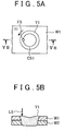
- FIG. 5A is a top view to describe an exemplary relationship between the molten pool, and the focal point and the scanning locus of the inspection laser beam in a case where the welding state of the welded portion is normal
- FIG. 5B is a view taken along an arrow VB-VB of FIG. 5A
- FIG. 6A is a top view to describe another exemplary relationship between the molten pool, and the focal point and the scanning locus of the inspection laser beam in the case where the welding state of the welded portion is normal
- FIG. 6A is a top view to describe another exemplary relationship between the molten pool, and the focal point and the scanning locus of the inspection laser beam in the case where the welding state of the welded portion is normal
- FIG. 5A is a top view to describe an exemplary relationship between the molten pool, and the focal point and
- FIG. 6B is a view taken along an arrow VIB-VIB of FIG. 6A .
- FIG. 7A is a top view to describe an exemplary relationship between the molten pool, and the focal point and the scanning locus of the inspection laser beam in a case where the welding state of the welded portion is poor
- FIG. 7B is a view taken along an arrow VIIB-VIIB of FIG. 7A
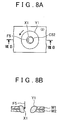
- FIG. 8A is a top view to describe another exemplary relationship between the molten pool, and the focal point and the scanning locus of the inspection laser beam in the case where the welding state of the welded portion is poor
- FIG. 8B is a view taken along an arrow VIIIB-VIIIB of FIG. 8A
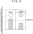
- FIG. 9 is a view illustrating ratios according to the present invention between average intensities of returned light beams in the case where the welding state of the welded portion is normal and in the case where the welding state of the welded portion is poor.
- the following cases are compared with each other: a case where the focal point F5 of the inspection laser beam L5 is rotated several times along the generally round-shaped scanning locus C51 set in the molten pool Y1 so as to radiate the inspection laser beam L5 several times on the scanning locus C51 (see FIGS. 5A and 5B ); and a case where the focal point F5 of the inspection laser beam L5 is rotated several times along the generally round-shaped scanning locus C52 having a radius smaller than that of the scanning locus C51 so as to radiate the inspection laser beam L5 several times on the scanning locus C52 (see FIGS.
- the intensity of the returned light beam L2 increases due to an increase of a workpiece temperature, and the like.
- the intensity of the returned light beam L2 received by the light-receiving portion 2 and transmitted to the inspection portion 6 via the conversion portion 3 and the amplifier 4 is larger in the case where the inspection laser beam L5 is radiated on the scanning locus C52 subsequently to the scanning locus C51 (a zone (2) in FIG. 4 ), as compared with the case where the inspection laser beam L5 is radiated several times on the scanning locus C51 (a zone (1) in FIG. 4 ).
- part of or all of the inspection laser beam L5 radiated from the inspection radiation portion 5 passes through the workpiece W1 or the workpiece W2 (see FIG. 8B ) depending on a positional relationship between the scanning locus set in the molten pool Y1 and a poor welding portion X1, so that an increase of the workpiece temperature is restrained.
- the welding state of the welded portion is poor (e.g., in a case of holed weld in which the workpieces are both molten and depressed)
- part of or all of the inspection laser beam L5 radiated from the inspection radiation portion 5 passes through the workpiece W1 or the workpiece W2 (see FIG. 8B ) depending on a positional relationship between the scanning locus set in the molten pool Y1 and a poor welding portion X1, so that an increase of the workpiece temperature is restrained.
- the intensity of the returned light beam L2 transmitted to the inspection portion 6 is equivalent to that intensity of the returned light beam L2 which is obtained when the welding state of the welded portion is normal.
- the focal point F5 of the inspection laser beam L5 is rotated several times along the generally round-shaped scanning locus C52 having a radius smaller than that of the scanning locus C51 so as to radiate the inspection laser beam L5 several times on the scanning locus C52 (see FIGS. 8A and 8B ) (the zone (2) in FIG. 4 ), the intensity of the returned light beam L2 transmitted to the inspection portion 6 is lower than that intensity of the returned light beam L2 which is obtained when the welding state of the welded portion is normal.
- the intensity of the returned light beam L2 received by the light-receiving portion 2 in the zone (1) illustrated in FIG. 4 (in that region inside the molten pool Y1 which is relatively spaced from the welding center CO) and an average intensity thereof are compared by the inspection portion 6 with the intensity of the returned light beam L2 received by the light-receiving portion 2 in the zone (2) illustrated in FIG. 4 (in that region inside the molten pool Y1 which is relatively close to the welding center CO) and an average intensity thereof.
- the electrical signal obtained from the returned light beam L2 is weak or even if the intensity of the returned light beam L2 changes according to a change of a workpiece temperature, for example, it is possible to inspect whether or not the poor welding portion X1 exists inside the outer edge of the molten pool Y1, that is, whether or not poor welding occurs in the welded portion formed in the workpieces W1, W2. More specifically, the average intensity of the returned light beam L2 received by the light-receiving portion 2 in the zone (1) illustrated in FIG. 4 and the average intensity of the returned light beam L2 received by the light-receiving portion 2 in the zone (2) are calculated. Then, according to the present invention, and as illustrated in FIG.
- a ratio (e.g., the zone (2)/the zone (1)) between both of the average intensities thus calculated is compared with a predetermined threshold.
- the inspection laser beam L5 is radiated to the molten pool Y1 along the generally round-shaped scanning loci C51, C52.
- the inspection laser beam L5 is radiated along the scanning loci C51, C52 set in the molten pool Y1 formed by radiation of the welding laser beam L1. Then, the welding state of the welded portion is inspected based on the intensity of the returned light beam L2 received by the light-receiving portion 2. Accordingly, for example, even in a case where a focal position of the welding laser beam is spaced from an occurrence position of the poor welding portion X1, it is possible to appropriately adjust a scanning condition (a scanning locus and the like) of the inspection laser beam L5. This makes it possible to minutely inspect the welding state of the welded portion formed in the workpieces.
- a periodic fluctuation of the intensity of the returned light beam L2 in the zone (1) shown in the continuous line in FIG. 4 or in the zone (2) shown in the dotted line in FIG. 4 is caused due to periodic vibration of a liquid level of the molten pool Y1 formed in the workpieces W1, W2 by radiation of the welding laser beam L1, for example. Further, it is considered that, in the zone (2) in the continuous line in FIG. 4 , no periodic fluctuation occurs in the intensity of the returned light beam L2 because part of or all of the inspection laser beam L5 radiated from the inspection radiation portion 5 passes through the workpieces W1, W2.
- Embodiment 2 of the welded portion inspection apparatus of the present invention With reference to FIG. 10 .
- FIG. 10 is an overall configuration diagram schematically illustrating an overall configuration of Embodiment 2 of the welded portion inspection apparatus of the present invention.
- An inspection apparatus 100A of Embodiment 2 as illustrated in FIG. 10 is different from the inspection apparatus 100 of Embodiment 1 as illustrated in FIG. 1 in that a welding state of a welded portion is inspected by use of reflection light of a welding laser beam radiated from a welding radiation portion.
- the other configuration is generally the same as the inspection apparatus 100 of Embodiment 1. Accordingly, constituents similar to those in Embodiment 1 have the same reference signs as those in Embodiment 1 and detailed descriptions thereof are omitted.
- the inspection apparatus 100A illustrated in the figure is mainly constituted by a welding radiation portion 1A, a light-receiving portion 2A, a conversion portion 3A, an amplifier 4A, an inspection portion 6A, and a CRT 7A.
- the welding radiation portion 1A radiates a welding laser beam L1A to the two workpieces W1, W2 via an optical system 8A and the light-receiving portion 2A.
- a molten pool Y1 where the workpieces W1, W2 are molten is formed on right and left sides of the welding laser beam L1A and behind the welding laser beam L1A in a traveling direction of the welding laser beam L1A.
- the light-receiving portion 2A receives a returned light beam L2A including reflection light of the welding laser light L1A radiated from the welding radiation portion 1A, the reflection light being reflected from the molten pool Y1 of the workpieces W1, W2, vapor light (plasma light) caused due to melting and evaporation of the workpieces W1, W2, thermal radiation light (infrared light) emitted from the molten pool Y1 of the workpieces W1, W2, and the like.
- a returned light beam L2A including reflection light of the welding laser light L1A radiated from the welding radiation portion 1A, the reflection light being reflected from the molten pool Y1 of the workpieces W1, W2, vapor light (plasma light) caused due to melting and evaporation of the workpieces W1, W2, thermal radiation light (infrared light) emitted from the molten pool Y1 of the workpieces W1, W2, and the like.
- the conversion portion 3A converts, into an electrical signal, the returned light beam L2A received by the light-receiving portion 2A and condensed via the optical system 8A and a condenser lens 9A, and outputs the electrical signal to the amplifier 4A.
- the amplifier 4A amplifies a signal intensity of the electrical signal output from the conversion portion 3A, and transmits it to the inspection portion 6A.
- the inspection portion 6A performs signal processing on the electrical signal transmitted from the amplifier 4A, and inspects a welding state of the welded portion formed in the workpieces W1, W2. More specifically, the inspection portion 6A calculates an average intensity of the returned light beam L2A received by the light-receiving portion 2A in a region inside an outer edge of the molten pool Y1 which is relatively close to the welding center C0 and an average intensity of the returned light beam L2A received by the light-receiving portion 2A in a region inside the outer edge of the molten pool Y1 which is relatively spaced from the welding center C0.
- the inspection portion 6A inspects the welding state of the welded portion formed in the workpieces W1, W2 based on a ratio between the average intensities of the returned light beams L2A. Further, the inspection portion 6A transmits, to the CRT 7A, a signal processing result on the electrical signal transmitted from the amplifier 4A. The CRT 7A displays the signal processing result transmitted from the inspection portion 6A.
- the welding state of the welded portion is poor, that is, in a case where a poor welding portion X1 is formed in the molten pool Y1 (e.g., in a case of holed weld)
- a poor welding portion X1 is formed in the molten pool Y1
- holed weld when the welding laser beam L1A is radiated from the welding radiation portion 1A to the workpieces W1, W2, for example, part of the welding laser beam L1A passes through the workpiece W1 or the workpiece W2, or the workpieces W1, W2 are partially lacked, so that an increase of a workpiece temperature is restrained.
- the inspection portion 6A compares the average intensity of the returned light beam L2A received in that region inside the molten pool Y1 which is relatively close to the welding center C0, with the average intensity of the returned light beam L2A received in that region inside the molten pool Y1 which is relatively spaced from the welding center C0.
- Embodiment 1 described above deals with an embodiment in which the center of the scanning locus of the inspection laser beam is set to the welding center of the welding locus of the welding laser beam.
- the embodiments described above deal with an embodiment in which the welding locus of the welding laser beam and the scanning locus of the inspection laser beam have a generally round shape.
- the welding locus of the welding laser beam and the scanning locus of the inspection laser beam may have a closed loop shape such as an elliptical shape or a polygonal shape, a spiral shape, or the like.
- the welding locus of the welding laser beam and the scanning locus of the inspection laser beam be set to pass through that part. Note that in a case where the welding locus of the welding laser beam has a generally round shape, the welding center is a center of the welding locus.
- the welding center can be set to, for example, a centroid of the welding locus.
- the welding center can be a center of the spiral of the welding locus.
- the above embodiments deal with an embodiment in which the intensity of the returned light beam received in that region inside the molten pool which is relatively close to the welding center is compared with the intensity of the returned light beam received in that region inside the molten pool which is relatively spaced from the welding center.
- the above embodiments mainly deal with an embodiment in which the average intensity of the returned light beam received in that region inside the molten pool which is relatively close to the welding center is compared with the average intensity of the returned light beam received in that region inside the molten pool which is relatively spaced from the welding center.
- part of the intensity of the returned light beam received in that region inside the molten pool which is relatively close to the welding center may be compared with part of the intensity of the returned light beam received in that region inside the molten pool which is relatively spaced from the welding center.
- the above embodiments deal with an embodiment in which the welding laser beam and the inspection laser beam are radiated to workpieces fixed to a predetermined position.
- focal positions of the welding laser beam and the inspection laser beam may be fixed and laser beam welding may be performed on the workpieces while the workpieces are being moved appropriately.
- laser beam welding may be performed on the workpieces such that the workpieces and the focal positions of the welding laser beam and the inspection laser beam are moved relative to each other.
- the inventor(s) of the present invention manufactured two types of inspection samples (Examples 1, 2) having different welding states, and performed intensity measurement of returned light beams from each of the inspection samples so as to evaluate a relationship of a welding state of a welded portion with a ratio between the average intensities of the returned light beams.
- the following generally describes a manufacturing method of an inspection sample and a measurement method of an intensity of a returned light beam from an inspection sample.
- Two workpieces each made from SCGA440 having a thickness of 0.7 mm were put on top of one another, and a welding laser beam was radiated to the workpieces along a generally round-shaped welding locus so as to form a generally round-shaped welded portion having a radius of about 2.5 mm.
- an inspection laser beam (with an output of 1000 W and at a scanning speed of 90 m/min) was radiated to go around ten times along a generally round-shaped scanning locus (with a welding center being taken as its center) having a radius of about 1.7 mm so as to pass through a molten pool formed in the workpieces.
- a focal point of the inspection laser beam was moved only by about 1.4 mm, and the inspection laser beam was radiated to go around ten times along a generally round-shaped scanning locus (with the welding center being taken as its center) having a radius of about 0.3 mm.
- a returned light beam including reflection light of the inspection laser beam which was reflected from the molten pool of the workpieces, vapor light caused by melting and evaporation of the workpieces, thermal radiation light emitted from the molten pool of the workpieces, and the like was received.
- the returned light beam thus received was converted into an electrical signal, and a signal intensity thereof was measured. Note that, in the returned light beam, particularly a signal intensity of the thermal radiation light (infrared light) emitted from the molten pool of the workpieces was measured in this experiment.
- FIG. 11A is a top view enlarging and illustrating a welded portion of the inspection sample according to Example 1
- FIG. 11B is a view taken along an arrow XIB-XIB in FIG. 11A
- FIG. 11C is a view illustrating an intensity of a returned light beam of the inspection sample according to Example 1 in time series.
- FIG. 12A is a top view enlarging and illustrating a welded portion of the inspection sample according to Example 2
- FIG. 12B is a view taken along an arrow XIIB-XIIB in FIG. 12A
- FIG. 12C is a view illustrating an intensity of a returned light beam of the inspection sample according to Example 2 in time series.
- an intensity of a returned light beam in a zone R2 (about 0.58 to about 0.60 sec) in which the inspection laser beam was radiated along the scanning locus having a radius of about 0.3 mm was relatively larger than an intensity of a returned light beam measured in a zone R1 (about 0.44 to about 0.46 sec) in which the inspection laser beam was radiated along the scanning locus having a radius of about 1.7 mm.
- the intensity of the returned light beam measured in the zone R2 included a periodic fluctuation.
- FIG. 13 is a view illustrating ratios (according to the present invention) between average intensities of returned light beams in the inspection samples according to Examples I, 2.
- the ratio between average intensities of returned light beams in each of the inspection samples according to Examples 1, 2 was calculated such that an average intensity (an intensity of a returned light beam per unit time) of the returned light beam measured in the zone R2 (about 0.58 to about 0.60 sec) where the inspection laser beam was radiated along the scanning locus having a radius of about 0.3 mm was divided by an average intensity (an intensity of a returned light beam per unit time) of the returned light beam measured in the zone R1 (about 0.44 to about 0.46 sec) where the inspection laser beam was radiated along the scanning locus having a radius of about 1.7 mm.
- FIG. 13 ten inspection samples were formed for each of Examples 1, 2, and that ratio between the average intensities of the returned light beams which was calculated about each inspection sample was illustrated.
- Example 1 the welding state is normal
- Example 2 holed weld
- the ratios between the average intensities of the returned light beams in the inspection samples of Example 1 were relatively larger than the ratios between the average intensities of the returned light beams in the inspection samples of Example 2.
Landscapes
- Engineering & Computer Science (AREA)
- Physics & Mathematics (AREA)
- Optics & Photonics (AREA)
- Mechanical Engineering (AREA)
- Plasma & Fusion (AREA)
- Quality & Reliability (AREA)
- General Physics & Mathematics (AREA)
- Laser Beam Processing (AREA)
- Investigating Materials By The Use Of Optical Means Adapted For Particular Applications (AREA)
Applications Claiming Priority (2)
| Application Number | Priority Date | Filing Date | Title |
|---|---|---|---|
| JP2013074837A JP5947741B2 (ja) | 2013-03-29 | 2013-03-29 | 溶接部の検査装置とその検査方法 |
| PCT/IB2014/000449 WO2014155190A2 (en) | 2013-03-29 | 2014-03-28 | Welded portion inspection apparatus and inspection method thereof |
Publications (2)
| Publication Number | Publication Date |
|---|---|
| EP2978556A2 EP2978556A2 (en) | 2016-02-03 |
| EP2978556B1 true EP2978556B1 (en) | 2017-07-26 |
Family
ID=50628861
Family Applications (1)
| Application Number | Title | Priority Date | Filing Date |
|---|---|---|---|
| EP14720691.6A Active EP2978556B1 (en) | 2013-03-29 | 2014-03-28 | Welded portion inspection apparatus and inspection method thereof, with inspection in different zones of the molten pool |
Country Status (7)
Cited By (1)
| Publication number | Priority date | Publication date | Assignee | Title |
|---|---|---|---|---|
| EP3797917B1 (en) * | 2019-06-28 | 2023-12-06 | Kabushiki Kaisha Yaskawa Denki | Laser welding state evaluation apparatus, method, system and program |
Families Citing this family (19)
| Publication number | Priority date | Publication date | Assignee | Title |
|---|---|---|---|---|
| JP5842851B2 (ja) | 2013-03-29 | 2016-01-13 | トヨタ自動車株式会社 | 溶接部の検査装置とその検査方法 |
| JP5947740B2 (ja) | 2013-03-29 | 2016-07-06 | トヨタ自動車株式会社 | 溶接部の検査装置とその検査方法 |
| JP5849985B2 (ja) | 2013-04-15 | 2016-02-03 | トヨタ自動車株式会社 | 溶接部の検査装置とその検査方法 |
| US10118249B2 (en) * | 2015-10-15 | 2018-11-06 | GM Global Technology Operations LLC | Laser beam welding with a spiral weld path having a first order of continuity |
| US20180361515A1 (en) * | 2016-01-14 | 2018-12-20 | Nissan Motor Co., Ltd. | Method for detecting hole in laser-welded portion and laser welding device |
| CN108778608B (zh) * | 2016-03-15 | 2020-11-17 | 杰富意钢铁株式会社 | 搭接激光焊接接头、该焊接接头的制造方法以及汽车用骨架部件 |
| JP6290960B2 (ja) * | 2016-04-04 | 2018-03-07 | ファナック株式会社 | 反射光強度を低減する機能を備えたレーザ加工装置 |
| WO2018227382A1 (en) * | 2017-06-13 | 2018-12-20 | GM Global Technology Operations LLC | Method for laser welding metal workpieces using a combination of weld paths |
| EP3753667B1 (en) * | 2018-02-16 | 2022-06-22 | Panasonic Intellectual Property Management Co., Ltd. | Laser welding device and laser welding method |
| CN111107959B (zh) * | 2018-02-16 | 2022-10-14 | 松下知识产权经营株式会社 | 激光焊接装置以及激光焊接方法 |
| CN111971143B (zh) * | 2018-04-13 | 2022-11-11 | 松下知识产权经营株式会社 | 激光焊接装置 |
| CN112334265B (zh) * | 2018-06-27 | 2023-02-17 | Smc株式会社 | 钢材的对焊接头及其制造方法 |
| DE102018217526A1 (de) * | 2018-10-12 | 2020-04-16 | Trumpf Werkzeugmaschinen Gmbh + Co. Kg | Verfahren zum Ermitteln einer Kenngröße eines Bearbeitungsprozesses und Bearbeitungsmaschine |
| JP7110907B2 (ja) * | 2018-10-26 | 2022-08-02 | トヨタ自動車株式会社 | 異種金属部材の重ね溶接方法 |
| DE102019103734A1 (de) * | 2019-02-14 | 2020-08-20 | Precitec Gmbh & Co. Kg | Laserbearbeitungssystem zur Bearbeitung eines Werkstücks mittels eines Laserstrahls und Verfahren zum Steuern eines Laserbearbeitungssystems |
| JP7390680B2 (ja) * | 2019-10-09 | 2023-12-04 | パナソニックIpマネジメント株式会社 | レーザ溶接品質検査の方法及びレーザ溶接品質検査装置 |
| EP3928913A1 (de) * | 2020-06-25 | 2021-12-29 | Bystronic Laser AG | Bearbeitungskopf und verfahren zur laserbearbeitung |
| CN112518125B (zh) * | 2020-11-25 | 2022-04-01 | 长春理工大学 | 一种激光点焊方法 |
| DE102021109787A1 (de) * | 2021-04-19 | 2022-10-20 | Precitec Gmbh & Co. Kg | Verfahren zum Vergleichen von Laserbearbeitungssystemen und Verfahren zum Überwachen eines Laserbearbeitungsprozesses sowie dazugehöriges Laserbearbeitungssystem |
Family Cites Families (24)
| Publication number | Priority date | Publication date | Assignee | Title |
|---|---|---|---|---|
| FR2547757B1 (fr) | 1983-06-27 | 1986-10-17 | Sciaky Sa | Procede et installation de soudage par point a faisceau laser |
| US5681490A (en) * | 1995-09-18 | 1997-10-28 | Chang; Dale U. | Laser weld quality monitoring system |
| US5651903A (en) * | 1995-10-12 | 1997-07-29 | Trw Inc. | Method and apparatus for evaluating laser welding |
| DE19630437C2 (de) * | 1996-07-27 | 2003-04-03 | Jurca Optoelektronik Gmbh | Detektorvorrichtung |
| RU2155653C2 (ru) * | 1998-06-08 | 2000-09-10 | Курский государственный технический университет | Видеосенсорное устройство |
| DE19852302A1 (de) | 1998-11-12 | 2000-05-25 | Fraunhofer Ges Forschung | Verfahren und Vorrichtung zum Bearbeiten von Werkstücken mit Hochenergiestrahlung |
| JP2000234918A (ja) * | 1999-02-16 | 2000-08-29 | Matsushita Electric Ind Co Ltd | レーザー溶接欠陥検査装置、及び欠陥検査方法 |
| DE19957163C1 (de) * | 1999-11-27 | 2001-08-09 | Thyssenkrupp Stahl Ag | Verfahren und Vorrichtung zur Qualitätskontrolle der Naht an mit einem Laser stumpf geschweißten Blechen oder Bändern |
| FR2811427B1 (fr) * | 2000-07-06 | 2002-10-25 | Aerospatiale Matra Ccr | Procede de detection et d'identification de defauts dans un cordon de soudure realise par faisceau laser |
| DE10103255B4 (de) * | 2001-01-25 | 2004-12-30 | Robert Bosch Gmbh | Verfahren zur automatischen Beurteilung von Laserbearbeitungsprozessen |
| SE521787C2 (sv) * | 2002-04-05 | 2003-12-09 | Volvo Aero Corp | Anordning och förfarande för kontroll av ett svetsområde, inrättning och förfarande för styrning av en svetsoperation, datorprogram och datorprogramprodukt |
| JP4026404B2 (ja) * | 2002-05-02 | 2007-12-26 | 日産自動車株式会社 | レーザー溶接部の品質モニタリング方法およびその装置 |
| DE102005010381B4 (de) * | 2005-03-07 | 2007-06-28 | Fraunhofer-Gesellschaft zur Förderung der angewandten Forschung e.V. | Verfahren zur Vermessung von Phasengrenzen eines Werkstoffes bei der Bearbeitung mit einem Bearbeitungsstrahl sowie zugehörige Vorrichtung |
| JP2007098464A (ja) * | 2005-10-07 | 2007-04-19 | Nissan Motor Co Ltd | レーザー加工ロボット制御装置、レーザー加工ロボット制御方法およびレーザー加工ロボット制御プログラム |
| CN100457353C (zh) * | 2006-04-25 | 2009-02-04 | 南京理工大学 | 焊缝外观、熔池和接缝近红外视觉一体化传感检测装置 |
| JP2008087056A (ja) | 2006-10-03 | 2008-04-17 | Toyota Motor Corp | レーザ溶接品質判定システムおよび品質判定方法 |
| CN102357739B (zh) * | 2006-10-04 | 2014-09-10 | 浜松光子学株式会社 | 激光加工方法 |
| JP2008272767A (ja) | 2007-04-26 | 2008-11-13 | Kanto Auto Works Ltd | レーザ溶接装置及びレーザ溶接の品質管理方法 |
| DE102007024789B3 (de) * | 2007-05-26 | 2008-10-23 | Trumpf Werkzeugmaschinen Gmbh + Co. Kg | Verfahren zum Erkennen von Fehlern an einer Schweißnaht während eines Laser-Schweißprozesses |
| US8592715B2 (en) * | 2008-11-27 | 2013-11-26 | Panasonic Corporation | Hybrid welding method and hybrid welding apparatus |
| DE102010016628A1 (de) * | 2010-02-26 | 2011-09-29 | Reis Group Holding Gmbh & Co. Kg | Verfahren und Anordnung zum stoffschlüssigen Verbinden von Materialien |
| JP5609595B2 (ja) * | 2010-12-01 | 2014-10-22 | トヨタ自動車株式会社 | レーザ溶接方法 |
| CZ2011408A3 (cs) * | 2011-07-04 | 2013-05-09 | Ústav prístrojové techniky Akademie ved CR, v.v.i. | Zarízení pro svarování laserem a zpusob rízení kvality svaru |
| JP5947740B2 (ja) | 2013-03-29 | 2016-07-06 | トヨタ自動車株式会社 | 溶接部の検査装置とその検査方法 |
-
2013
- 2013-03-29 JP JP2013074837A patent/JP5947741B2/ja not_active Expired - Fee Related
-
2014
- 2014-03-28 EP EP14720691.6A patent/EP2978556B1/en active Active
- 2014-03-28 US US14/781,129 patent/US9517533B2/en active Active
- 2014-03-28 RU RU2015141109A patent/RU2638140C2/ru active
- 2014-03-28 WO PCT/IB2014/000449 patent/WO2014155190A2/en active Application Filing
- 2014-03-28 CN CN201480018867.8A patent/CN105073331B/zh active Active
- 2014-03-28 BR BR112015024725A patent/BR112015024725B8/pt not_active IP Right Cessation
Non-Patent Citations (1)
| Title |
|---|
| None * |
Cited By (1)
| Publication number | Priority date | Publication date | Assignee | Title |
|---|---|---|---|---|
| EP3797917B1 (en) * | 2019-06-28 | 2023-12-06 | Kabushiki Kaisha Yaskawa Denki | Laser welding state evaluation apparatus, method, system and program |
Also Published As
| Publication number | Publication date |
|---|---|
| CN105073331B (zh) | 2017-04-12 |
| BR112015024725B8 (pt) | 2022-05-10 |
| EP2978556A2 (en) | 2016-02-03 |
| CN105073331A (zh) | 2015-11-18 |
| US20160052091A1 (en) | 2016-02-25 |
| WO2014155190A8 (en) | 2015-07-23 |
| RU2015141109A (ru) | 2017-05-04 |
| RU2638140C2 (ru) | 2017-12-11 |
| WO2014155190A3 (en) | 2014-12-11 |
| BR112015024725B1 (pt) | 2022-03-03 |
| US9517533B2 (en) | 2016-12-13 |
| JP5947741B2 (ja) | 2016-07-06 |
| BR112015024725A2 (pt) | 2017-07-18 |
| JP2014198345A (ja) | 2014-10-23 |
| WO2014155190A2 (en) | 2014-10-02 |
Similar Documents
| Publication | Publication Date | Title |
|---|---|---|
| EP2978556B1 (en) | Welded portion inspection apparatus and inspection method thereof, with inspection in different zones of the molten pool | |
| EP2978560B1 (en) | Welded portion inspection apparatus and inspection method thereof | |
| RU2635586C2 (ru) | Устройство контроля сварного участка и способ его контроля с выделяющим участком для выделения свечения испарения и теплового излучения | |
| EP2978555B1 (en) | Welding portion inspection method and inspection device therefor | |
| US9969028B2 (en) | Welded portion inspection method | |
| US20150266131A1 (en) | Laser welding inspection apparatus and laser welding inspection method |
Legal Events
| Date | Code | Title | Description |
|---|---|---|---|
| PUAI | Public reference made under article 153(3) epc to a published international application that has entered the european phase |
Free format text: ORIGINAL CODE: 0009012 |
|
| 17P | Request for examination filed |
Effective date: 20150929 |
|
| AK | Designated contracting states |
Kind code of ref document: A2 Designated state(s): AL AT BE BG CH CY CZ DE DK EE ES FI FR GB GR HR HU IE IS IT LI LT LU LV MC MK MT NL NO PL PT RO RS SE SI SK SM TR |
|
| AX | Request for extension of the european patent |
Extension state: BA ME |
|
| DAX | Request for extension of the european patent (deleted) | ||
| 17Q | First examination report despatched |
Effective date: 20160610 |
|
| GRAP | Despatch of communication of intention to grant a patent |
Free format text: ORIGINAL CODE: EPIDOSNIGR1 |
|
| INTG | Intention to grant announced |
Effective date: 20170302 |
|
| GRAS | Grant fee paid |
Free format text: ORIGINAL CODE: EPIDOSNIGR3 |
|
| GRAA | (expected) grant |
Free format text: ORIGINAL CODE: 0009210 |
|
| AK | Designated contracting states |
Kind code of ref document: B1 Designated state(s): AL AT BE BG CH CY CZ DE DK EE ES FI FR GB GR HR HU IE IS IT LI LT LU LV MC MK MT NL NO PL PT RO RS SE SI SK SM TR |
|
| REG | Reference to a national code |
Ref country code: GB Ref legal event code: FG4D |
|
| REG | Reference to a national code |
Ref country code: CH Ref legal event code: EP |
|
| REG | Reference to a national code |
Ref country code: AT Ref legal event code: REF Ref document number: 911982 Country of ref document: AT Kind code of ref document: T Effective date: 20170815 |
|
| REG | Reference to a national code |
Ref country code: IE Ref legal event code: FG4D |
|
| REG | Reference to a national code |
Ref country code: DE Ref legal event code: R096 Ref document number: 602014012266 Country of ref document: DE |
|
| REG | Reference to a national code |
Ref country code: NL Ref legal event code: MP Effective date: 20170726 |
|
| REG | Reference to a national code |
Ref country code: LT Ref legal event code: MG4D |
|
| REG | Reference to a national code |
Ref country code: AT Ref legal event code: MK05 Ref document number: 911982 Country of ref document: AT Kind code of ref document: T Effective date: 20170726 |
|
| REG | Reference to a national code |
Ref country code: DE Ref legal event code: R084 Ref document number: 602014012266 Country of ref document: DE |
|
| PG25 | Lapsed in a contracting state [announced via postgrant information from national office to epo] |
Ref country code: FI Free format text: LAPSE BECAUSE OF FAILURE TO SUBMIT A TRANSLATION OF THE DESCRIPTION OR TO PAY THE FEE WITHIN THE PRESCRIBED TIME-LIMIT Effective date: 20170726 Ref country code: SE Free format text: LAPSE BECAUSE OF FAILURE TO SUBMIT A TRANSLATION OF THE DESCRIPTION OR TO PAY THE FEE WITHIN THE PRESCRIBED TIME-LIMIT Effective date: 20170726 Ref country code: LT Free format text: LAPSE BECAUSE OF FAILURE TO SUBMIT A TRANSLATION OF THE DESCRIPTION OR TO PAY THE FEE WITHIN THE PRESCRIBED TIME-LIMIT Effective date: 20170726 Ref country code: AT Free format text: LAPSE BECAUSE OF FAILURE TO SUBMIT A TRANSLATION OF THE DESCRIPTION OR TO PAY THE FEE WITHIN THE PRESCRIBED TIME-LIMIT Effective date: 20170726 Ref country code: NO Free format text: LAPSE BECAUSE OF FAILURE TO SUBMIT A TRANSLATION OF THE DESCRIPTION OR TO PAY THE FEE WITHIN THE PRESCRIBED TIME-LIMIT Effective date: 20171026 Ref country code: NL Free format text: LAPSE BECAUSE OF FAILURE TO SUBMIT A TRANSLATION OF THE DESCRIPTION OR TO PAY THE FEE WITHIN THE PRESCRIBED TIME-LIMIT Effective date: 20170726 Ref country code: HR Free format text: LAPSE BECAUSE OF FAILURE TO SUBMIT A TRANSLATION OF THE DESCRIPTION OR TO PAY THE FEE WITHIN THE PRESCRIBED TIME-LIMIT Effective date: 20170726 |
|
| REG | Reference to a national code |
Ref country code: GB Ref legal event code: 746 Effective date: 20180110 |
|
| REG | Reference to a national code |
Ref country code: FR Ref legal event code: PLFP Year of fee payment: 5 |
|
| PG25 | Lapsed in a contracting state [announced via postgrant information from national office to epo] |
Ref country code: PL Free format text: LAPSE BECAUSE OF FAILURE TO SUBMIT A TRANSLATION OF THE DESCRIPTION OR TO PAY THE FEE WITHIN THE PRESCRIBED TIME-LIMIT Effective date: 20170726 Ref country code: LV Free format text: LAPSE BECAUSE OF FAILURE TO SUBMIT A TRANSLATION OF THE DESCRIPTION OR TO PAY THE FEE WITHIN THE PRESCRIBED TIME-LIMIT Effective date: 20170726 Ref country code: BG Free format text: LAPSE BECAUSE OF FAILURE TO SUBMIT A TRANSLATION OF THE DESCRIPTION OR TO PAY THE FEE WITHIN THE PRESCRIBED TIME-LIMIT Effective date: 20171026 Ref country code: RS Free format text: LAPSE BECAUSE OF FAILURE TO SUBMIT A TRANSLATION OF THE DESCRIPTION OR TO PAY THE FEE WITHIN THE PRESCRIBED TIME-LIMIT Effective date: 20170726 Ref country code: GR Free format text: LAPSE BECAUSE OF FAILURE TO SUBMIT A TRANSLATION OF THE DESCRIPTION OR TO PAY THE FEE WITHIN THE PRESCRIBED TIME-LIMIT Effective date: 20171027 Ref country code: IS Free format text: LAPSE BECAUSE OF FAILURE TO SUBMIT A TRANSLATION OF THE DESCRIPTION OR TO PAY THE FEE WITHIN THE PRESCRIBED TIME-LIMIT Effective date: 20171126 Ref country code: ES Free format text: LAPSE BECAUSE OF FAILURE TO SUBMIT A TRANSLATION OF THE DESCRIPTION OR TO PAY THE FEE WITHIN THE PRESCRIBED TIME-LIMIT Effective date: 20170726 |
|
| PG25 | Lapsed in a contracting state [announced via postgrant information from national office to epo] |
Ref country code: CZ Free format text: LAPSE BECAUSE OF FAILURE TO SUBMIT A TRANSLATION OF THE DESCRIPTION OR TO PAY THE FEE WITHIN THE PRESCRIBED TIME-LIMIT Effective date: 20170726 Ref country code: DK Free format text: LAPSE BECAUSE OF FAILURE TO SUBMIT A TRANSLATION OF THE DESCRIPTION OR TO PAY THE FEE WITHIN THE PRESCRIBED TIME-LIMIT Effective date: 20170726 Ref country code: RO Free format text: LAPSE BECAUSE OF FAILURE TO SUBMIT A TRANSLATION OF THE DESCRIPTION OR TO PAY THE FEE WITHIN THE PRESCRIBED TIME-LIMIT Effective date: 20170726 |
|
| REG | Reference to a national code |
Ref country code: DE Ref legal event code: R097 Ref document number: 602014012266 Country of ref document: DE |
|
| PG25 | Lapsed in a contracting state [announced via postgrant information from national office to epo] |
Ref country code: SK Free format text: LAPSE BECAUSE OF FAILURE TO SUBMIT A TRANSLATION OF THE DESCRIPTION OR TO PAY THE FEE WITHIN THE PRESCRIBED TIME-LIMIT Effective date: 20170726 Ref country code: IT Free format text: LAPSE BECAUSE OF FAILURE TO SUBMIT A TRANSLATION OF THE DESCRIPTION OR TO PAY THE FEE WITHIN THE PRESCRIBED TIME-LIMIT Effective date: 20170726 Ref country code: SM Free format text: LAPSE BECAUSE OF FAILURE TO SUBMIT A TRANSLATION OF THE DESCRIPTION OR TO PAY THE FEE WITHIN THE PRESCRIBED TIME-LIMIT Effective date: 20170726 Ref country code: EE Free format text: LAPSE BECAUSE OF FAILURE TO SUBMIT A TRANSLATION OF THE DESCRIPTION OR TO PAY THE FEE WITHIN THE PRESCRIBED TIME-LIMIT Effective date: 20170726 |
|
| PLBE | No opposition filed within time limit |
Free format text: ORIGINAL CODE: 0009261 |
|
| STAA | Information on the status of an ep patent application or granted ep patent |
Free format text: STATUS: NO OPPOSITION FILED WITHIN TIME LIMIT |
|
| 26N | No opposition filed |
Effective date: 20180430 |
|
| PG25 | Lapsed in a contracting state [announced via postgrant information from national office to epo] |
Ref country code: SI Free format text: LAPSE BECAUSE OF FAILURE TO SUBMIT A TRANSLATION OF THE DESCRIPTION OR TO PAY THE FEE WITHIN THE PRESCRIBED TIME-LIMIT Effective date: 20170726 |
|
| REG | Reference to a national code |
Ref country code: CH Ref legal event code: PL |
|
| PG25 | Lapsed in a contracting state [announced via postgrant information from national office to epo] |
Ref country code: MC Free format text: LAPSE BECAUSE OF FAILURE TO SUBMIT A TRANSLATION OF THE DESCRIPTION OR TO PAY THE FEE WITHIN THE PRESCRIBED TIME-LIMIT Effective date: 20170726 |
|
| REG | Reference to a national code |
Ref country code: BE Ref legal event code: MM Effective date: 20180331 |
|
| REG | Reference to a national code |
Ref country code: IE Ref legal event code: MM4A |
|
| PG25 | Lapsed in a contracting state [announced via postgrant information from national office to epo] |
Ref country code: LU Free format text: LAPSE BECAUSE OF NON-PAYMENT OF DUE FEES Effective date: 20180328 |
|
| PG25 | Lapsed in a contracting state [announced via postgrant information from national office to epo] |
Ref country code: IE Free format text: LAPSE BECAUSE OF NON-PAYMENT OF DUE FEES Effective date: 20180328 |
|
| PG25 | Lapsed in a contracting state [announced via postgrant information from national office to epo] |
Ref country code: LI Free format text: LAPSE BECAUSE OF NON-PAYMENT OF DUE FEES Effective date: 20180331 Ref country code: CH Free format text: LAPSE BECAUSE OF NON-PAYMENT OF DUE FEES Effective date: 20180331 Ref country code: BE Free format text: LAPSE BECAUSE OF NON-PAYMENT OF DUE FEES Effective date: 20180331 |
|
| PG25 | Lapsed in a contracting state [announced via postgrant information from national office to epo] |
Ref country code: MT Free format text: LAPSE BECAUSE OF NON-PAYMENT OF DUE FEES Effective date: 20180328 |
|
| PG25 | Lapsed in a contracting state [announced via postgrant information from national office to epo] |
Ref country code: TR Free format text: LAPSE BECAUSE OF FAILURE TO SUBMIT A TRANSLATION OF THE DESCRIPTION OR TO PAY THE FEE WITHIN THE PRESCRIBED TIME-LIMIT Effective date: 20170726 |
|
| PG25 | Lapsed in a contracting state [announced via postgrant information from national office to epo] |
Ref country code: PT Free format text: LAPSE BECAUSE OF FAILURE TO SUBMIT A TRANSLATION OF THE DESCRIPTION OR TO PAY THE FEE WITHIN THE PRESCRIBED TIME-LIMIT Effective date: 20170726 |
|
| PG25 | Lapsed in a contracting state [announced via postgrant information from national office to epo] |
Ref country code: HU Free format text: LAPSE BECAUSE OF FAILURE TO SUBMIT A TRANSLATION OF THE DESCRIPTION OR TO PAY THE FEE WITHIN THE PRESCRIBED TIME-LIMIT; INVALID AB INITIO Effective date: 20140328 Ref country code: CY Free format text: LAPSE BECAUSE OF FAILURE TO SUBMIT A TRANSLATION OF THE DESCRIPTION OR TO PAY THE FEE WITHIN THE PRESCRIBED TIME-LIMIT Effective date: 20170726 Ref country code: MK Free format text: LAPSE BECAUSE OF NON-PAYMENT OF DUE FEES Effective date: 20170726 |
|
| PG25 | Lapsed in a contracting state [announced via postgrant information from national office to epo] |
Ref country code: AL Free format text: LAPSE BECAUSE OF FAILURE TO SUBMIT A TRANSLATION OF THE DESCRIPTION OR TO PAY THE FEE WITHIN THE PRESCRIBED TIME-LIMIT Effective date: 20170726 |
|
| P01 | Opt-out of the competence of the unified patent court (upc) registered |
Effective date: 20230427 |
|
| PGFP | Annual fee paid to national office [announced via postgrant information from national office to epo] |
Ref country code: DE Payment date: 20250128 Year of fee payment: 12 |
|
| PGFP | Annual fee paid to national office [announced via postgrant information from national office to epo] |
Ref country code: FR Payment date: 20250210 Year of fee payment: 12 |
|
| PGFP | Annual fee paid to national office [announced via postgrant information from national office to epo] |
Ref country code: GB Payment date: 20250206 Year of fee payment: 12 |