EP2978124B1 - Stromerzeugungseinheit und motorgeneratorsteuerungsverfahren - Google Patents
Stromerzeugungseinheit und motorgeneratorsteuerungsverfahren Download PDFInfo
- Publication number
- EP2978124B1 EP2978124B1 EP13878969.8A EP13878969A EP2978124B1 EP 2978124 B1 EP2978124 B1 EP 2978124B1 EP 13878969 A EP13878969 A EP 13878969A EP 2978124 B1 EP2978124 B1 EP 2978124B1
- Authority
- EP
- European Patent Office
- Prior art keywords
- state
- coils
- rotations
- threshold
- phases
- Prior art date
- Legal status (The legal status is an assumption and is not a legal conclusion. Google has not performed a legal analysis and makes no representation as to the accuracy of the status listed.)
- Active
Links
Images









Classifications
-
- F—MECHANICAL ENGINEERING; LIGHTING; HEATING; WEAPONS; BLASTING
- F02—COMBUSTION ENGINES; HOT-GAS OR COMBUSTION-PRODUCT ENGINE PLANTS
- F02N—STARTING OF COMBUSTION ENGINES; STARTING AIDS FOR SUCH ENGINES, NOT OTHERWISE PROVIDED FOR
- F02N11/00—Starting of engines by means of electric motors
- F02N11/08—Circuits specially adapted for starting of engines
- F02N11/0814—Circuits specially adapted for starting of engines comprising means for controlling automatic idle-start-stop
-
- B—PERFORMING OPERATIONS; TRANSPORTING
- B60—VEHICLES IN GENERAL
- B60K—ARRANGEMENT OR MOUNTING OF PROPULSION UNITS OR OF TRANSMISSIONS IN VEHICLES; ARRANGEMENT OR MOUNTING OF PLURAL DIVERSE PRIME-MOVERS IN VEHICLES; AUXILIARY DRIVES FOR VEHICLES; INSTRUMENTATION OR DASHBOARDS FOR VEHICLES; ARRANGEMENTS IN CONNECTION WITH COOLING, AIR INTAKE, GAS EXHAUST OR FUEL SUPPLY OF PROPULSION UNITS IN VEHICLES
- B60K6/00—Arrangement or mounting of plural diverse prime-movers for mutual or common propulsion, e.g. hybrid propulsion systems comprising electric motors and internal combustion engines
- B60K6/20—Arrangement or mounting of plural diverse prime-movers for mutual or common propulsion, e.g. hybrid propulsion systems comprising electric motors and internal combustion engines the prime-movers consisting of electric motors and internal combustion engines, e.g. HEVs
- B60K6/22—Arrangement or mounting of plural diverse prime-movers for mutual or common propulsion, e.g. hybrid propulsion systems comprising electric motors and internal combustion engines the prime-movers consisting of electric motors and internal combustion engines, e.g. HEVs characterised by apparatus, components or means specially adapted for HEVs
- B60K6/26—Arrangement or mounting of plural diverse prime-movers for mutual or common propulsion, e.g. hybrid propulsion systems comprising electric motors and internal combustion engines the prime-movers consisting of electric motors and internal combustion engines, e.g. HEVs characterised by apparatus, components or means specially adapted for HEVs characterised by the motors or the generators
-
- B—PERFORMING OPERATIONS; TRANSPORTING
- B60—VEHICLES IN GENERAL
- B60K—ARRANGEMENT OR MOUNTING OF PROPULSION UNITS OR OF TRANSMISSIONS IN VEHICLES; ARRANGEMENT OR MOUNTING OF PLURAL DIVERSE PRIME-MOVERS IN VEHICLES; AUXILIARY DRIVES FOR VEHICLES; INSTRUMENTATION OR DASHBOARDS FOR VEHICLES; ARRANGEMENTS IN CONNECTION WITH COOLING, AIR INTAKE, GAS EXHAUST OR FUEL SUPPLY OF PROPULSION UNITS IN VEHICLES
- B60K6/00—Arrangement or mounting of plural diverse prime-movers for mutual or common propulsion, e.g. hybrid propulsion systems comprising electric motors and internal combustion engines
- B60K6/20—Arrangement or mounting of plural diverse prime-movers for mutual or common propulsion, e.g. hybrid propulsion systems comprising electric motors and internal combustion engines the prime-movers consisting of electric motors and internal combustion engines, e.g. HEVs
- B60K6/42—Arrangement or mounting of plural diverse prime-movers for mutual or common propulsion, e.g. hybrid propulsion systems comprising electric motors and internal combustion engines the prime-movers consisting of electric motors and internal combustion engines, e.g. HEVs characterised by the architecture of the hybrid electric vehicle
- B60K6/48—Parallel type
- B60K6/485—Motor-assist type
-
- F—MECHANICAL ENGINEERING; LIGHTING; HEATING; WEAPONS; BLASTING
- F02—COMBUSTION ENGINES; HOT-GAS OR COMBUSTION-PRODUCT ENGINE PLANTS
- F02B—INTERNAL-COMBUSTION PISTON ENGINES; COMBUSTION ENGINES IN GENERAL
- F02B61/00—Adaptations of engines for driving vehicles or for driving propellers; Combinations of engines with gearing
- F02B61/02—Adaptations of engines for driving vehicles or for driving propellers; Combinations of engines with gearing for driving cycles
-
- F—MECHANICAL ENGINEERING; LIGHTING; HEATING; WEAPONS; BLASTING
- F02—COMBUSTION ENGINES; HOT-GAS OR COMBUSTION-PRODUCT ENGINE PLANTS
- F02B—INTERNAL-COMBUSTION PISTON ENGINES; COMBUSTION ENGINES IN GENERAL
- F02B63/00—Adaptations of engines for driving pumps, hand-held tools or electric generators; Portable combinations of engines with engine-driven devices
- F02B63/04—Adaptations of engines for driving pumps, hand-held tools or electric generators; Portable combinations of engines with engine-driven devices for electric generators
-
- F—MECHANICAL ENGINEERING; LIGHTING; HEATING; WEAPONS; BLASTING
- F02—COMBUSTION ENGINES; HOT-GAS OR COMBUSTION-PRODUCT ENGINE PLANTS
- F02N—STARTING OF COMBUSTION ENGINES; STARTING AIDS FOR SUCH ENGINES, NOT OTHERWISE PROVIDED FOR
- F02N11/00—Starting of engines by means of electric motors
- F02N11/04—Starting of engines by means of electric motors the motors being associated with current generators
-
- F—MECHANICAL ENGINEERING; LIGHTING; HEATING; WEAPONS; BLASTING
- F02—COMBUSTION ENGINES; HOT-GAS OR COMBUSTION-PRODUCT ENGINE PLANTS
- F02N—STARTING OF COMBUSTION ENGINES; STARTING AIDS FOR SUCH ENGINES, NOT OTHERWISE PROVIDED FOR
- F02N11/00—Starting of engines by means of electric motors
- F02N11/08—Circuits specially adapted for starting of engines
- F02N11/0859—Circuits specially adapted for starting of engines specially adapted to the type of the starter motor or integrated into it
-
- H—ELECTRICITY
- H02—GENERATION; CONVERSION OR DISTRIBUTION OF ELECTRIC POWER
- H02J—ELECTRIC POWER NETWORKS; CIRCUIT ARRANGEMENTS OR SYSTEMS FOR SUPPLYING OR DISTRIBUTING ELECTRIC POWER; SYSTEMS FOR STORING ELECTRIC ENERGY
- H02J7/00—Circuit arrangements for charging or discharging batteries or for supplying loads from batteries
- H02J7/14—Circuit arrangements for charging or discharging batteries or for supplying loads from batteries for charging batteries from dynamo-electric generators driven at varying speed, e.g. on vehicle
- H02J7/1469—Regulation of the charging current or voltage otherwise than by variation of field
- H02J7/1484—Regulation of the charging current or voltage otherwise than by variation of field by commutation of the output windings of the generator
-
- H—ELECTRICITY
- H02—GENERATION; CONVERSION OR DISTRIBUTION OF ELECTRIC POWER
- H02J—ELECTRIC POWER NETWORKS; CIRCUIT ARRANGEMENTS OR SYSTEMS FOR SUPPLYING OR DISTRIBUTING ELECTRIC POWER; SYSTEMS FOR STORING ELECTRIC ENERGY
- H02J7/00—Circuit arrangements for charging or discharging batteries or for supplying loads from batteries
- H02J7/14—Circuit arrangements for charging or discharging batteries or for supplying loads from batteries for charging batteries from dynamo-electric generators driven at varying speed, e.g. on vehicle
- H02J7/16—Regulation of the charging current or voltage by variation of field
-
- H—ELECTRICITY
- H02—GENERATION; CONVERSION OR DISTRIBUTION OF ELECTRIC POWER
- H02K—DYNAMO-ELECTRIC MACHINES
- H02K21/00—Synchronous motors having permanent magnets; Synchronous generators having permanent magnets
- H02K21/12—Synchronous motors having permanent magnets; Synchronous generators having permanent magnets with stationary armatures and rotating magnets
- H02K21/22—Synchronous motors having permanent magnets; Synchronous generators having permanent magnets with stationary armatures and rotating magnets with magnets rotating around the armatures, e.g. flywheel magnetos
-
- H—ELECTRICITY
- H02—GENERATION; CONVERSION OR DISTRIBUTION OF ELECTRIC POWER
- H02P—CONTROL OR REGULATION OF ELECTRIC MOTORS, ELECTRIC GENERATORS OR DYNAMO-ELECTRIC CONVERTERS; CONTROLLING TRANSFORMERS, REACTORS OR CHOKE COILS
- H02P27/00—Arrangements or methods for the control of AC motors characterised by the kind of supply voltage
- H02P27/04—Arrangements or methods for the control of AC motors characterised by the kind of supply voltage using variable-frequency supply voltage, e.g. inverter or converter supply voltage
- H02P27/06—Arrangements or methods for the control of AC motors characterised by the kind of supply voltage using variable-frequency supply voltage, e.g. inverter or converter supply voltage using DC to AC converters or inverters
- H02P27/08—Arrangements or methods for the control of AC motors characterised by the kind of supply voltage using variable-frequency supply voltage, e.g. inverter or converter supply voltage using DC to AC converters or inverters with pulse width modulation
- H02P27/085—Arrangements or methods for the control of AC motors characterised by the kind of supply voltage using variable-frequency supply voltage, e.g. inverter or converter supply voltage using DC to AC converters or inverters with pulse width modulation wherein the PWM mode is adapted on the running conditions of the motor, e.g. the switching frequency
-
- H—ELECTRICITY
- H02—GENERATION; CONVERSION OR DISTRIBUTION OF ELECTRIC POWER
- H02P—CONTROL OR REGULATION OF ELECTRIC MOTORS, ELECTRIC GENERATORS OR DYNAMO-ELECTRIC CONVERTERS; CONTROLLING TRANSFORMERS, REACTORS OR CHOKE COILS
- H02P9/00—Arrangements for controlling electric generators for the purpose of obtaining a desired output
- H02P9/48—Arrangements for obtaining a constant output value at varying speed of the generator, e.g. on vehicle
-
- B—PERFORMING OPERATIONS; TRANSPORTING
- B60—VEHICLES IN GENERAL
- B60K—ARRANGEMENT OR MOUNTING OF PROPULSION UNITS OR OF TRANSMISSIONS IN VEHICLES; ARRANGEMENT OR MOUNTING OF PLURAL DIVERSE PRIME-MOVERS IN VEHICLES; AUXILIARY DRIVES FOR VEHICLES; INSTRUMENTATION OR DASHBOARDS FOR VEHICLES; ARRANGEMENTS IN CONNECTION WITH COOLING, AIR INTAKE, GAS EXHAUST OR FUEL SUPPLY OF PROPULSION UNITS IN VEHICLES
- B60K6/00—Arrangement or mounting of plural diverse prime-movers for mutual or common propulsion, e.g. hybrid propulsion systems comprising electric motors and internal combustion engines
- B60K6/20—Arrangement or mounting of plural diverse prime-movers for mutual or common propulsion, e.g. hybrid propulsion systems comprising electric motors and internal combustion engines the prime-movers consisting of electric motors and internal combustion engines, e.g. HEVs
- B60K6/22—Arrangement or mounting of plural diverse prime-movers for mutual or common propulsion, e.g. hybrid propulsion systems comprising electric motors and internal combustion engines the prime-movers consisting of electric motors and internal combustion engines, e.g. HEVs characterised by apparatus, components or means specially adapted for HEVs
- B60K6/26—Arrangement or mounting of plural diverse prime-movers for mutual or common propulsion, e.g. hybrid propulsion systems comprising electric motors and internal combustion engines the prime-movers consisting of electric motors and internal combustion engines, e.g. HEVs characterised by apparatus, components or means specially adapted for HEVs characterised by the motors or the generators
- B60K2006/264—Arrangement or mounting of plural diverse prime-movers for mutual or common propulsion, e.g. hybrid propulsion systems comprising electric motors and internal combustion engines the prime-movers consisting of electric motors and internal combustion engines, e.g. HEVs characterised by apparatus, components or means specially adapted for HEVs characterised by the motors or the generators with outer rotor and inner stator
-
- B—PERFORMING OPERATIONS; TRANSPORTING
- B60—VEHICLES IN GENERAL
- B60L—PROPULSION OF ELECTRICALLY-PROPELLED VEHICLES; SUPPLYING ELECTRIC POWER FOR AUXILIARY EQUIPMENT OF ELECTRICALLY-PROPELLED VEHICLES; ELECTRODYNAMIC BRAKE SYSTEMS FOR VEHICLES IN GENERAL; MAGNETIC SUSPENSION OR LEVITATION FOR VEHICLES; MONITORING OPERATING VARIABLES OF ELECTRICALLY-PROPELLED VEHICLES; ELECTRIC SAFETY DEVICES FOR ELECTRICALLY-PROPELLED VEHICLES
- B60L2220/00—Electrical machine types; Structures or applications thereof
- B60L2220/10—Electrical machine types
- B60L2220/14—Synchronous machines
-
- B—PERFORMING OPERATIONS; TRANSPORTING
- B60—VEHICLES IN GENERAL
- B60L—PROPULSION OF ELECTRICALLY-PROPELLED VEHICLES; SUPPLYING ELECTRIC POWER FOR AUXILIARY EQUIPMENT OF ELECTRICALLY-PROPELLED VEHICLES; ELECTRODYNAMIC BRAKE SYSTEMS FOR VEHICLES IN GENERAL; MAGNETIC SUSPENSION OR LEVITATION FOR VEHICLES; MONITORING OPERATING VARIABLES OF ELECTRICALLY-PROPELLED VEHICLES; ELECTRIC SAFETY DEVICES FOR ELECTRICALLY-PROPELLED VEHICLES
- B60L2220/00—Electrical machine types; Structures or applications thereof
- B60L2220/50—Structural details of electrical machines
- B60L2220/56—Structural details of electrical machines with switched windings
-
- B—PERFORMING OPERATIONS; TRANSPORTING
- B60—VEHICLES IN GENERAL
- B60Y—INDEXING SCHEME RELATING TO ASPECTS CROSS-CUTTING VEHICLE TECHNOLOGY
- B60Y2400/00—Special features of vehicle units
- B60Y2400/47—Starter generator drive systems
-
- F—MECHANICAL ENGINEERING; LIGHTING; HEATING; WEAPONS; BLASTING
- F02—COMBUSTION ENGINES; HOT-GAS OR COMBUSTION-PRODUCT ENGINE PLANTS
- F02D—CONTROLLING COMBUSTION ENGINES
- F02D29/00—Controlling engines, such controlling being peculiar to the devices driven thereby, the devices being other than parts or accessories essential to engine operation, e.g. controlling of engines by signals external thereto
- F02D29/06—Controlling engines, such controlling being peculiar to the devices driven thereby, the devices being other than parts or accessories essential to engine operation, e.g. controlling of engines by signals external thereto peculiar to engines driving electric generators
-
- F—MECHANICAL ENGINEERING; LIGHTING; HEATING; WEAPONS; BLASTING
- F02—COMBUSTION ENGINES; HOT-GAS OR COMBUSTION-PRODUCT ENGINE PLANTS
- F02N—STARTING OF COMBUSTION ENGINES; STARTING AIDS FOR SUCH ENGINES, NOT OTHERWISE PROVIDED FOR
- F02N2200/00—Parameters used for control of starting apparatus
- F02N2200/06—Parameters used for control of starting apparatus said parameters being related to the power supply or driving circuits for the starter
- F02N2200/062—Battery current
-
- F—MECHANICAL ENGINEERING; LIGHTING; HEATING; WEAPONS; BLASTING
- F02—COMBUSTION ENGINES; HOT-GAS OR COMBUSTION-PRODUCT ENGINE PLANTS
- F02N—STARTING OF COMBUSTION ENGINES; STARTING AIDS FOR SUCH ENGINES, NOT OTHERWISE PROVIDED FOR
- F02N2200/00—Parameters used for control of starting apparatus
- F02N2200/06—Parameters used for control of starting apparatus said parameters being related to the power supply or driving circuits for the starter
- F02N2200/063—Battery voltage
-
- F—MECHANICAL ENGINEERING; LIGHTING; HEATING; WEAPONS; BLASTING
- F02—COMBUSTION ENGINES; HOT-GAS OR COMBUSTION-PRODUCT ENGINE PLANTS
- F02N—STARTING OF COMBUSTION ENGINES; STARTING AIDS FOR SUCH ENGINES, NOT OTHERWISE PROVIDED FOR
- F02N2200/00—Parameters used for control of starting apparatus
- F02N2200/10—Parameters used for control of starting apparatus said parameters being related to driver demands or status
- F02N2200/101—Accelerator pedal position
-
- Y—GENERAL TAGGING OF NEW TECHNOLOGICAL DEVELOPMENTS; GENERAL TAGGING OF CROSS-SECTIONAL TECHNOLOGIES SPANNING OVER SEVERAL SECTIONS OF THE IPC; TECHNICAL SUBJECTS COVERED BY FORMER USPC CROSS-REFERENCE ART COLLECTIONS [XRACs] AND DIGESTS
- Y02—TECHNOLOGIES OR APPLICATIONS FOR MITIGATION OR ADAPTATION AGAINST CLIMATE CHANGE
- Y02T—CLIMATE CHANGE MITIGATION TECHNOLOGIES RELATED TO TRANSPORTATION
- Y02T10/00—Road transport of goods or passengers
- Y02T10/10—Internal combustion engine [ICE] based vehicles
- Y02T10/40—Engine management systems
-
- Y—GENERAL TAGGING OF NEW TECHNOLOGICAL DEVELOPMENTS; GENERAL TAGGING OF CROSS-SECTIONAL TECHNOLOGIES SPANNING OVER SEVERAL SECTIONS OF THE IPC; TECHNICAL SUBJECTS COVERED BY FORMER USPC CROSS-REFERENCE ART COLLECTIONS [XRACs] AND DIGESTS
- Y02—TECHNOLOGIES OR APPLICATIONS FOR MITIGATION OR ADAPTATION AGAINST CLIMATE CHANGE
- Y02T—CLIMATE CHANGE MITIGATION TECHNOLOGIES RELATED TO TRANSPORTATION
- Y02T10/00—Road transport of goods or passengers
- Y02T10/60—Other road transportation technologies with climate change mitigation effect
- Y02T10/62—Hybrid vehicles
-
- Y—GENERAL TAGGING OF NEW TECHNOLOGICAL DEVELOPMENTS; GENERAL TAGGING OF CROSS-SECTIONAL TECHNOLOGIES SPANNING OVER SEVERAL SECTIONS OF THE IPC; TECHNICAL SUBJECTS COVERED BY FORMER USPC CROSS-REFERENCE ART COLLECTIONS [XRACs] AND DIGESTS
- Y02—TECHNOLOGIES OR APPLICATIONS FOR MITIGATION OR ADAPTATION AGAINST CLIMATE CHANGE
- Y02T—CLIMATE CHANGE MITIGATION TECHNOLOGIES RELATED TO TRANSPORTATION
- Y02T10/00—Road transport of goods or passengers
- Y02T10/60—Other road transportation technologies with climate change mitigation effect
- Y02T10/64—Electric machine technologies in electromobility
Definitions
- the present invention relates to a power generation unit and a motor generator control method.
- motors three-phase motors that are driven in three phases have been widely used.
- three-phase motors coils of respective phases are connected to each other at neutral positions thereof, and electric currents are not independently applied to the coils of the respective phases.
- an invention of an electric power steering apparatus equipped with a motor having a connection relationship in which coils of respective phases can be independently driven is disclosed (for example, refer to Patent Document 1). If the coils of the respective phases can be independently driven, a larger torque can be output as compared to the case where the coils of the respective phases are connected to each other.
- an invention of a motor generator that functions as a starter motor at the time of starting an engine and functions as a generator after the engine is started is disclosed (refer to Patent Document 2).
- the motor generator of such an aspect may be referred to as an alternating current generator (ACG) starter.
- ACG starter By using the ACG starter, the need for including a related-art cell motor type starter disappears. For this reason, weight and costs can be reduced, and generation of noise caused by a reduction gear that couples a cell motor type starter and a crankshaft together can be eliminated.
- the ACG starter is preferably used because mechanical noise at the time of the starting of the engine is suppressed.
- a power generation unit using a magneto alternating current generator is known from US 2011/0101930 .
- US 2005/258790 A1 discloses a power generation unit in accordance with the preamble of claim 1.
- the ACG starter is coupled to the crankshaft without being coupled via the reduction gear. Therefore, a method by which to obtain enough torque act on the crankshaft to overcome compression occurring on a top dead center of the engine at the time of starting the engine is an issue.
- aspects of the invention have been made in consideration of such circumstances, and an object thereof is to provide a power generation unit and a motor generator control method capable of improving torque output performance while suppressing an increase in friction.
- the stator in which the coils of each phase are not connected to each other is included and control is performed so that the coil of each phase is brought into any one of a plurality of states including the first state in which torque is generated by the rotor, the second state in which both ends of the coil are electrically released, and the third state in which both ends of the coil are short-circuited. Therefore, torque output performance can be improved while suppressing an increase in friction.
- the internal combustion engine is started when all the coils of the three or more phases are brought into the first state. Therefore, torque for overcoming compression on the top dead center of the internal combustion engine can be output.
- powering control of the motor generator is performed while making at least some coils among the three or more phases in the first state until the number of rotations of the internal combustion engine becomes equal to or greater than the predetermined number of rotations after an acceleration instruction is given to the vehicle in the stopped state or in the state in which the vehicle travels at low speed. Therefore, the acceleration ability at the time of starting moving in the vehicle can be improved.
- FIG. 19 is a view illustrating a wiring structure centered on an ACG starter of a power generation unit related to a third example useful for understanding the invention.
- FIG. 1 is a configuration view illustrating an example of an overall configuration of a motorcycle 1 on which an ACG starter (motor generator) 60 related to each of the embodiments of the invention is mounted.
- an engine unit 2 is mounted at the center in a vehicle body front-rear direction, a seat 3 on which an occupant sits down is provided above a rear portion of the engine unit 2, and a fuel tank 4 is provided below the seat 3.
- a head lamp (lighting device) HL is provided at the front of the motorcycle 1.
- a front wheel Wf is rotatably supported by a front fork 5.
- a steering handle 6 is provided at an upper portion of the front fork 5.
- a brake lever (not illustrated) and a throttle grip (not illustrated) are arranged on the right side of the steering handle 6.
- a rear wheel Wr is swingably supported by a vehicle body frame via a swing arm 7.
- FIG. 2 is a developed cross-sectional view of the engine unit 2 corresponding to an A-A cross-section of FIG. 1 .
- a reciprocal engine 10 that is an internal combustion engine that outputs a driving force for traveling, and a multistage transmission 11 are constituted as an integral block.
- the engine 10 and the transmission 11 are configured so that power can be transmitted via a centrifugal clutch 8 and a transmission clutch 12.
- a piston 14 is slidably fitted into a cylinder bore of a cylinder block 13.
- the piston 14 is coupled to a crankshaft (rotation output shaft) 16 via a connecting rod 15.
- the engine 10, as illustrated in FIG. 1 is mounted on a vehicle in a substantially horizontal posture in which the cylinder block 13 extends to the front of the vehicle body with respect to the crankshaft 16.
- crankshaft 16 is rotatably supported via a bearing 18 to a crankcase 17 which is combined with a base end portion of the cylinder block 13. Additionally, a cylinder head 20 that forms a combustion chamber 19 between the cylinder head and the piston 14 is attached to a tip portion of the cylinder block 13.
- reference sign 21 in FIG. 2 represents an ignition device that is installed in the cylinder head 20 so as to face the inside of the combustion chamber 19.
- reference sign 22 represents a valve gear that is provided on a tip side of the cylinder head 20 to drive the opening and closing of an intake/exhaust valve (not illustrated) while interlocking with the crankshaft 16 and is covered with a head cover 20C.
- reference sign 23 of FIG. 2 represents crank webs provided on both sides in an axial direction of a coupling portion (crankpin) with the connecting rod 15 on the crankshaft 16.
- reference sign 17a represents a crank chamber within a crankcase 17 that houses substantially the entire region of the crankshaft 16.
- the centrifugal clutch 8 is provided at the outer periphery (the outer periphery closer to the outer side in the axial direction than the crank webs 23) of one end portion (an end portion on the right side of a paper surface of FIG. 2 , hereinafter referred to as a right end portion) of the crankshaft 16 in the axial direction.
- the centrifugal clutch 8 is equipped with an inner clutch 24 that is integrally fixed to the right end portion of the crankshaft 16, an outer clutch 25 that is rotatably supported by the outer periphery of the right end portion of the crankshaft 16, and a centrifugal weight 26 that rotates integrally with the inner clutch 24 and brings the inner clutch 24 and the outer clutch 25 into a connected state due to a centrifugal force.
- the centrifugal clutch 8 outputs the rotational power of the crankshaft 16 to the outer clutch 25 when the rotating speed of the crankshaft 16 reaches a predetermined speed or higher.
- a main shaft 29 and a counter shaft 30 of the transmission 11 are provided parallel to the crankshaft 16 at positions closer to the vehicle rear side than a rotation center O of the crankshaft 16 within the crankcase 17.
- the main shaft 29 and the counter shaft 30 are rotatably supported within the crankcase 17 via a pair of bearings, which are arranged apart from each other, respectively. Additionally, the main shaft 29 is arranged at a position adjacent to the vehicle rear side of the crankshaft 16, and the counter shaft 30 is arranged at a position adjacent to the vehicle rear side of the main shaft 29.
- a main shift gear group M1 is disposed on the main shaft 29 of the transmission 11.
- a counter gear group M2 that meshes with a main gear group M1 is disposed on the counter shaft 30.
- the input gear 27 meshing with the output gear 28 on the crankshaft 16 side and the transmission clutch 12 are provided at one end portion (an end portion on the right side of the paper surface of FIG. 2 , hereinafter referred to as a right end portion) of the main shaft 29 in the axial direction.
- the input gear 27 is rotatably supported on the outer periphery of the main shaft 29. Additionally, an output sprocket 33 is attached to the other end portion (an end portion on the left side of the paper surface of FIG. 2 ) of the counter shaft 30 in the axial direction. A chain for power transmission (not illustrated) is hung around on the output sprocket 33, and the rotation of the counter shaft 30 is transmitted to the rear wheel Wr that is a driving wheel via the chain.
- a driving transmission gear of the main gear group M1 and the counter gear group M2 is selected by rotational operation of a shift drum (not illustrated) provided within the crankcase 17, and thereby, an arbitrary shift gear stage (gear position) that includes neutral is set.
- the transmission clutch 12 is equipped with an outer clutch 35, the inner clutch 36, a plurality of driving friction plates 37, a plurality of driven friction plates 38, a clutch spring (not illustrated), and an operating plate 40.
- the outer clutch 35 has a bottomed cylindrical shape that is rotatably supported on the main shaft 29 in a state in which the outer clutch is combined integrally with the input gear 27.
- the inner clutch 36 has a substantially disc-like shape that is spline-fitted to the main shaft 29.
- the plurality of driving friction plates 37 are integrally rotatably locked to the outer clutch 35.
- the plurality of the driven friction plates 38 are integrally rotatably locked to the inner clutch 36 and come into frictional contact with the driving friction plates 37.
- the clutch spring biases the driving friction plates 37 and the driven friction plates 38 in a pressure contact direction.
- the operation panel 40 operates to release the biasing force of the clutch spring that acts between the driving friction plates 37 and the driven friction plates 38.
- the driving friction plates 37 on the outer clutch 35 side and the driven friction plates 38 on the inner clutch 36 side are arranged alternately in the axial direction, and are pressed against each other under the biasing force of the clutch spring. Accordingly, the power transmission between the outer clutch 35 and the inner clutch 36 becomes possible. Additionally, by operating to release the biasing force of the clutch spring using the operating plate 40, the power transmission between the inner clutch 36 the outer clutch 35 is cut off.
- the operating plate 40 is configured so as to be movable back and forth in the axial direction while interlocking with the operation of a shift pedal (not illustrated).
- the shift pedal When the shift pedal is operated, the operating plate 40 releases the biasing force of the clutch spring that acts between the driving friction plates 37 and the driven friction plates 38 for a predetermined period before a shift gear meshes therewith, and thereby stops the power transmission between the outer clutch 35 and the inner clutch 36.
- a state in which the driving friction plates 37 and the driven friction plates 38 mesh with each other is brought about.
- a kick spindle 42 of a kick starter 41 is rotatably attached to a lower side of a rear portion of the crankcase 17.
- the kick spindle 42 transmits its rotation to the crankshaft 16 only when the kick pedal 43 is stepped on.
- the other end portion (an end portion on the left side of the paper surface of FIG. 2 , hereinafter referred to as a left end portion) of the crankshaft 16 in the axial direction passes through a circular opening 17b formed in a side wall (wall portion) of the crankcase 17 and protrudes to the outside from the side wall of the crankcase 17.
- An ACG starter 60 which also serves as an AC generator and a starting motor of the engine 10, is attached to a left end portion side of the crankshaft 16 protruding from the opening 17b of the crankcase 17.
- the left end portion of the crankshaft 16 is covered with a concave engine cover 51 attached to the side wall of the crankcase 17 by being fastened with a bolt or the like.
- the engine cover 51 is equipped with a bottom wall portion 51a and a side wall portion 51b (cover portion).
- the bottom wall portion 51a covers the left end portion of the crankshaft 16 from the left side.
- the side wall portion 51b extends so as to rise from an outer peripheral edge of the bottom wall portion 51a, abuts against the side wall of the crankcase 17 at the tip thereof, and is combined with the crankcase 17.
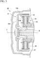
- FIG. 3 illustrates an example of a cross-sectional view of the ACG starter 60 related to the first embodiment.
- the ACG starter 60 is equipped with a rotor 61 that rotates integrally with the crankshaft 16, and a stator 65.
- the rotor 61 has magnets.
- the rotor 61 has a substantially cylindrical shape, a bottom wall portion 61A forms a disk surface, and an opening is formed on a side opposite to the bottom wall portion 61A and introduces the crankshaft 16 therethrough.
- Magnets 62 are attached to or formed on an inner circumferential face 61B of a side wall portion of the rotor 61.
- a first stator 65 for example, is coupled to the crankcase 17 and is housed inside the rotor 61 in its radial direction.
- the first stator 65 is equipped with a plurality of external-teeth-shaped stator cores 66 that protrude in the direction of the rotor 61 and around which coils are wound.
- the stator cores 66 make magnetic flux, which is generated by applying an electric current to the coils, and act on the magnets 62, thereby generating torque in the rotor 61.
- the first stator 65 takes out an induced current generated by the rotation of the rotor 61 accompanying the traveling of the motorcycle 1, and generates electric power.
- the electric power generated from the first stator 65 is stored in a battery 80 (to be described below).
- the first stator 65 has a structure in which the stator cores 66 have, for example, eighteen poles, and a U pole, a V pole, and W pole are sequentially arranged one by one.
- a total of twelve magnets 62 for example, are provided such that a magnet in which a side facing a stator core 66 is an S pole and a magnet in which a side facing a stator core 66 is an N pole are alternately arranged.
- FIG. 4 is a view illustrating an example of a control-related configuration of the ACG starter 60.
- the ACG starter 60 is controlled by a controller 70 (driving control part) and a driving part 72 (driving control part).
- the controller 70 is, for example, a microcomputer centered on a central processing unit (CPU) 71.
- the controller 70 acquires rotation information from a Hall IC (not illustrated) of the ACG starter 60.
- the rotational angle information of the crankshaft 16, or the like may be acquired from a crank angle sensor or a control device of the engine 10.
- the controller 70 calculates the number of rotations N of the rotor 61 on the basis of the rotation information of the ACG starter 60.
- the driving part 72 is equipped with, for example, a plurality of switching elements (to be described below) for controlling the ACG starter 60 in three phases which are a U phase, a V phase, and a W phase.
- the plurality of switching elements have bridge circuits that sandwiches the coils therebetween.
- the controller 70 drives (powers) the ACG starter 60, for example, according to a start signal input from an ignition switch 74, and outputs torque for starting the engine 10 to the ACG starter 60.
- This start signal may be input from the control device of the engine 10.
- the powering control of the ACG starter 60 may be performed for outputting an assistance torque at the time of starting moving in the motorcycle 1.
- the ACG starter 60 is made to generate (regenerate) electric power using the output of the engine 10 according to the charge state of the battery 80, and charges the battery 80.
- the controller 70 generates a control signal sent to switching element groups (UTr1 to UTr5, VTr1 to VTr5, and WTr1 to WTr5; will be described below) for performing this phase regulation control, and outputs the control signal to the driving part 72.
- Information on the voltage between terminals of the battery 80 or the amounts of charge and discharge currents is input to the controller 70 from a voltage sensor 82 or a current sensor 84 attached to the battery 80.
- the controller 70 estimates the charge state (charging rate) of the battery 80 on the basis of the voltage between the terminals of the battery 80, or calculates the charge state (charging rate) of the battery 80 by integrating the amounts of charge and discharge currents.
- the battery 80 supplies electric power for driving the ACG starter 60 or electric power for allowing other electrical components (for example, a head lamp or the like) to operate.
- FIG. 5 is a view illustrating the relationship between wound coils in the ACG starter 60 and the driving part 72.
- the magnet 62 includes an N pole 62a in which a side facing a stator core 66 is an N pole, and an S pole 62b in which a side facing a stator core 66 is an S pole.
- FIG. 6 is a view illustrating a driving structure of a general motor in which three-phase coils are connected to each other.
- a current Iq that contributes torque is the total of components which directly travels in the direction of magnetic flux of the rotor 61. Therefore, if the impedance of each phase is defined as Z and the voltage of the battery is defined as Vb, the following Expression (1) is established.
- torque Tq proportional to the current Iq can be output.
- FIG. 7 is a view illustrating an example of the state changes of respective switching elements when the power generation unit performs the powering control.
- the controller 70 brings the V phase and the W phase into a state in which power generation is not performed, for example, when only the U phase is used for power generation and when electric power of a degree such that the battery 80 mounted on the motorcycle 1 is charged and various electrical components are driven can be taken out. Accordingly, friction can be reduced as compared to a case where all of the three phases are used for power generation.
- the power generation unit can select either a state (open state) in which both ends of a coil are released or a state (short-circuited state) in which both the ends of the coil are short-circuited, as "the state in which power generation is not performed”. Even when power generation is not performed, a certain degree of friction torque is generated, but this friction torque has properties such that it changes according to the number of rotations of the rotor 61.
- FIG. 8 is a view illustrating properties of the friction torque according to the number of rotations of the rotor 61.
- a friction torque Fs when the short-circuited state is brought about becomes larger than a friction torque Fo when the open state is brought about
- the friction torque Fs where the short-circuited state is brought about becomes lower than the friction torque Fo in the case where the open state is brought about.
- Fo represents a friction torque in a state in which generated electric power is taken out.
- the ideal threshold Na is an adaptation value that is determined on the basis of the size of the ACG motor 60, the number of times the coils are wound, the number of poles, or the like.
- the controller 70 of the present embodiment brings the V-phase and W-phase coils into the open state when the number of rotations N of the rotor 61 is in the low rotation range, and brings the V-phase and W-phase coils into the short-circuited state when the number of rotations N of the rotor 61 is in the high rotation range. Accordingly, the friction can be further reduced as compared to a case where either the open state or the short-circuited state is maintained in the entire rotation range.
- FIG. 9 illustrates an example of a flowchart illustrating a flow of processing executed by the controller 70 of the first embodiment. The processing of the flowchart of FIG. 9 is repeatedly executed until the engine 10 stops after being started.
- the controller 70 determines whether or not the number of rotations N of the rotor 61 is lower than a first threshold N1 (predetermined number of rotations) (Step S100). When the number of rotations N of the rotor 61 is lower than the first threshold N1, the controller 70 makes the U-phase coil operate as a phase regulator to take out generated electric power and bring the V-phase and W-phase coils into the open state (Step S102), and ends one routine in the processing of the flowchart of FIG. 9 .
- a first threshold N1 predetermined number of rotations
- the controller 70 makes the U-phase coil operate as a phase regulator and brings the V-phase and W-phase coils into the short-circuited state (Step S104). Then, the controller 70 maintains the V-phase and W-phase coils in the short-circuited state until the number of rotations N of the rotor 61 becomes lower than the second threshold N2 (Step S106).
- N1 > N2 is established between the first threshold N1 and the second threshold N2.
- the threshold N1 and the threshold N2 are values near the aforementioned ideal threshold Na. Accordingly, hunting in which switching between states is frequently performed can be prevented from occurring, and fluctuations of the friction can be suppressed.
- the controller 70 makes the U-phase coil operate as a phase regulator and brings the V-phase and W-phase coils into the open state (Step S102), and ends one routine in the processing of the flowchart of FIG. 9 .
- FIG. 10 is a view illustrating the state transition of the V phase and the W phase realized through the above control.
- the number of rotations N of the rotor 61 is near zero at the time of the starting of the engine 10, and the V-phase and W-phase coils are brought into the open state. If the number of rotations N of the rotor 61 increases from here and becomes equal to or greater than the threshold N1, the V-phase and W-phase coils are brought into the short-circuited state. Thereafter, if the number of rotations N of the rotor 61 decreases and becomes lower than the threshold N2 which is lower than the threshold N1, the V-phase and W-phase coils are brought into the open state.
- FIG. 11 is a view illustrating an example of the state changes of the respective switching elements when the V-phase and W-phase coils are brought into the open state.
- electric power operates as a phase regulator. That is, the phase of an energization pattern having a magnetic pole position as a basis thereof varies according to a voltage.
- all the switching elements VTr1 to VTr5 and WTr1 to WTr5 are maintained in an OFF state.
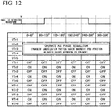
- FIG. 12 is a view illustrating an example of the state changes of the respective switching elements when the V-phase and W-phase coils are brought into the short-circuited state.
- the U phase in which power generation is performed is controlled to operate as a phase regulator.
- the switching elements VTr2, VTr4, WTr2, and WTr4 are brought into an ON state, and both ends of the coil in each phase are maintained in the short-circuited state.
- the switching elements on the negative electrode side of the battery connected to (the power generation unit) the switching element are brought into the ON state, and the switching elements on the positive electrode side thereof are brought into the OFF state.
- the switching elements VTr1, VTr3, WTr1, and WTr3 may be brought into the ON state.
- the three-phase coils are not connected to each other, and energization in the respective phases is controlled by the exclusive switching element groups. Therefore, a larger torque can be output as compared to a case where the coils of the respective phases are connected to each other.
- the controller 70 uses only the U phase for power generation and brings the V phase and the W phase into a state in which power generation is not performed. Therefore, the friction can be reduced as compared to a case where all of the three phases are used for power generation. As a result, torque output performance can be improved by suppressing an increase in friction while avoiding enlargement of the ACG starter 60.
- the power generation unit of the present embodiment can select either the state (open state) in which both ends of a coil are released or a state (short-circuited state) in which both the ends of the coil are short-circuited, as "the state in which power generation is not performed”.
- the controller 70 of the present embodiment brings the V-phase and W-phase coils into the open state when the number of rotations N of the rotor 61 is in the low rotation range, and brings the V-phase and W-phase coils into the short-circuited state when the number of rotations N of the rotor 61 is in the high rotation range. Therefore, the friction can be further reduced as compared to a case where either the open state or the short-circuited state is maintained in the entire rotation range.
- FIGS. 1 to 7 will be referred to and repeated description thereof will be omitted.
- the controller 70 related to the first example useful for understanding the invention estimates or calculates the charging rate of the battery 80 on the basis of information on a voltage or a current input from the battery 80, and dynamically changes control at the time of the regenerative control on the basis of the charging rate of the battery 80.
- FIG. 13 illustrates an example of a flowchart illustrating a flow of processing executed by the controller 70 of the first example useful for understanding the invention. The processing of the flowchart of FIG. 13 is repeatedly executed until the engine 10 stops after being started.
- the controller 70 determines whether or not a charging rate P representing the charge state of the battery 80 is equal to or greater than a threshold (predetermined level) P1 (for example, about 50[%]) (Step S200).
- a threshold for example, about 50[%]
- the charging rate P of the battery 80 and the voltage between the terminals of the battery 80 has a certain degree of correlation. Therefore, the determination in Step S200 may be performed by comparing the voltage between the terminals of the battery 80 with a threshold. The same applies below.
- Step S202 the controller 70 determines whether or not the number of rotations N of the rotor 61 is lower than the first threshold N1 (Step S202).
- the controller 70 makes the U-phase coil operate as a phase regulator and brings the V-phase and W-phase coils into the open state (Step S204), and ends one routine in the processing of the flowchart of FIG. 13 .
- Step S210 when the number of rotations N of the rotor 61 is equal to or greater than the first threshold N1 in Step S202, the controller 70 makes the U-phase coil operate as a phase regulator and brings the V-phase and W-phase coils into the short-circuited state (Step S206). Then, the controller 70 maintains the V-phase and W-phase coils in the short-circuited state until the number of rotations N of the rotor 61 becomes lower than the second threshold N2 (Step S208). However, if the charging rate P of the battery 80 becomes lower than the threshold PI, the controller 70 proceeds to Step S212 (Step S210).
- N1 > N2 is established between the first threshold N1 and the second threshold N2.
- the threshold N1 and the threshold N2 are values near the aforementioned ideal threshold Na. Accordingly, hunting in which switching between states is frequently performed can be prevented from occurring, and fluctuations of the friction can be suppressed.
- Step S208 the controller 70 makes the U-phase coil operate as a phase regulator and brings the V-phase and W-phase coils into the open state (Step S204), and ends one routine in the processing of the flowchart of FIG. 13 .
- the controller 70 makes coils of two or more phases operate as phase regulators, and generates electric power (Step S212).
- the controller 70 may make coils of two phases among U phase, V phase, and W phase operate as phase regulators, or may make coils of all the phases operate as phase regulators.
- switching may be performed between the open state and the short-circuited state according to the number of rotations of the rotor 61 similar to Steps S202 to S208.
- the controller 70 (driving control part) makes some coils among of a plurality of phases generate electric power using the rotary power of the engine 10 (internal combustion engine), charges the battery 80 with this generated electric power, and brings some other coils among of the plurality of phases into the open state or the short-circuited state, and when the charge state of the battery 80 is lower than a predetermined level, the controller makes the coils of phases, which has more phases than the phases of the some other coils when the charge state of a battery 80 is equal to or greater than the predetermined level, generate electric power using the rotary power of the engine 10 (internal combustion engine).
- the power generation unit related to the first example useful for understanding the invention can flexibly increase the amount of power generation of the ACG starter 60, when the charging rate of the battery 80 is low and can rapidly charge the battery 80. As a result, a possibility that battery exhaustion occurs in the battery 80 can be reduced.
- the same effects as those of the first embodiment can be exhibited. Also, when the charging rate of the battery 80 is low, the amount of power generation can be flexibly increased, and the battery 80 can be rapidly charged.
- FIGS. 1 to 3 and 5 to 7 will be referred to and repeated description thereof will be omitted.
- FIG. 14 is a view illustrating an example of a control-related configuration of the ACG starter 60 of the second example useful for understanding the invention.
- an accelerator opening signal representing an accelerator opening degree AC is input from an accelerator opening sensor 76 to the controller 70.
- the accelerator opening sensor 76 detects the amount of rotation of a rotary shaft, which extends from a throttle grip to which an acceleration instruction is input by a driver and which is rotated by a throttle wire, as the accelerator opening degree AC.
- the controller 70 related to the second example useful for understanding the invention dynamically changes the control at the time of the regenerative control, on the basis of the information showing the acceleration instruction given to the motorcycle 1, such as the accelerator opening degree AC input from the accelerator opening sensor 76, and the charging rate (refer to the first example useful for understanding the invention) of the battery 80.
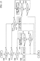
- FIG. 15 illustrates an example of a flowchart illustrating a flow of processing executed by the controller 70 of the second example useful for understanding the invention. The processing of the flowchart of FIG. 15 is repeatedly executed until the engine 10 stops after being started.
- the controller 70 determines whether or not the accelerator opening degree AC input from the accelerator opening sensor 76 is equal to or greater than a threshold A1 (for example, about 50[%]) (Step S300).
- a threshold A1 for example, about 50[%]
- information such as vehicle speed or acceleration, in addition to the accelerator opening, may be considered in this determination.
- the controller 70 determines whether or not the charging rate P showing the charge state of the battery 80 is equal to or greater than the threshold (predetermined level) P1 (for example, about 50[%]) (Step S302).
- Step S304 the controller 70 determines whether or not the number of rotations N of the rotor 61 is lower than the first threshold N1 (Step S304).
- the controller 70 brings the coils of all the phases into the open state (Step S306), and ends one routine in the processing of the flowchart of FIG. 15 .
- Step S304 when the number of rotations N of the rotor 61 is equal to or greater than the first threshold N1 in Step S304, the controller 70 brings the coils of all the phases into the short-circuited state (Step S308). Then, the controller 70 maintains the V-phase and W-phase coils in the short-circuited state until the number of rotations N of the rotor 61 becomes lower than the second threshold N2 (Step S310). However, the controller 70 ends one routine in the processing of the flowchart of FIG. 15 if the accelerator opening degree AC becomes lower than the threshold A1 (Step S312).
- Step S310 the controller 70 brings the coils of all the phases into the open state (Step S306), and ends one routine in the processing of the flowchart of FIG. 15 .
- Step S314 when the accelerator opening degree AC input from the accelerator opening sensor 76 is lower than the threshold A1 in Step S300, or when the charging rate P of the battery 80 is lower than the threshold P1 in Step S302, the controller 70 determines whether or not the number of rotations N of the rotor 61 is lower than the first threshold N1 (Step S314).
- Step S314 When the number of rotations N of the rotor 61 is lower than the first threshold N1 in Step S314, the controller 70 makes the U-phase coil operate as a phase regulator and brings the V-phase and W-phase coils into the open state (Step S316), and ends one routine in the processing of the flowchart of FIG. 15 .
- Step S314 when the number of rotations N of the rotor 61 is equal to or greater than the first threshold N1 in Step S314, the controller 70 makes the U-phase coil operate as a phase regulator and brings the V-phase and W-phase coils into the short-circuited state (Step S318).
- the controller 70 maintains the V-phase and W-phase coils in the short-circuited state until the number of rotations N of the rotor 61 becomes lower than the second threshold N2 (Step S320). However, the controller 70 ends one routine in the processing of the flowchart of FIG. 15 if the accelerator opening degree AC becomes equal to or greater than the threshold A1 (Step S322).
- N1 > N2 a relationship of N1 > N2 is established between the first threshold N1 and the second threshold N2. Accordingly, the hunting can be prevented from occurring.
- Step S320 the controller 70 makes the U-phase coil operate as a phase regulator and brings the V-phase and W-phase coils into the open state (Step S316), and ends one routine in the processing of the flowchart of FIG. 15 .
- the controller 70 (driving control part) brings all coils of a plurality of phases into the open state or the short-circuited state, and when the charge state of the battery 80 is lower than the predetermined level, the controller 70 makes some coils among of the plurality of phases generate electric power using the rotary power of the engine 10 (internal combustion engine), charges the battery 80 with this generated electric power, and brings some other coils among of the plurality of phases into the open state or the short-circuited state.
- the power generation unit related to the second example useful for understanding the invention brings the coils of all the phases into the open state or the short-circuited state if there is an excessive charging amount regarding the charging rate of the battery 80 when an acceleration instruction given to the motorcycle 1 is made by a driver. Therefore, the friction can be further reduced and the acceleration ability of the motorcycle 1 can be improved.
- the same effects as those of the first embodiment can be exhibited, and also the friction can be further reduced and the acceleration ability of the motorcycle 1 can be improved.
- the power generation unit related to the second example useful for understanding the invention may be operated in conjunction with the processing described in the first example useful for understanding the invention. That is, (1) when the accelerator opening degree AC is equal to or greater than the threshold and the charging rate P of the battery 80 is equal to or greater than the threshold PI, the controller 70 brings the coils of all the phases into the open state or the short-circuited state, and (2) when the accelerator opening degree AC is lower than the threshold and the charging rate P of the battery 80 is equal to or greater than the threshold PI, the controller 70 makes only the U-phase coil operate as a phase regulator, and (3) when the charging rate P of the battery 80 is lower than the threshold P1 irrespective of the accelerator opening degree AC, the controller 70 makes coils of two or more phases operate as phase regulators.
- FIG. 16 is a view illustrating an example of a control-related configuration of the ACG starter 60 of the first embodiment.
- the accelerator opening signal showing the accelerator opening degree AC is input from the accelerator opening sensor 76 to the controller 70.
- a speed signal showing a vehicle speed V is input from the vehicle speed sensor 78 to the controller 70.
- a crank angle signal showing a crank angle ⁇ is input from a crank angle sensor 79 to the controller 70.
- the vehicle speed sensor 78 is attached to a wheel, the transmission 11, the crankshaft 16, and the like, and detects the speed of the motorcycle.
- the crank angle sensor 79 detects the rotational angle of the crankshaft 16.
- the controller 70 related to the first embodiment performs acceleration assistant control at the time of starting moving, on the basis of the accelerator opening degree AC input from the accelerator opening sensor 76 and the vehicle speed V input from the vehicle speed sensor 78.
- FIG. 17 illustrates an example of the flowchart illustrating the flow of the processing executed by the controller 70 of the first embodiment. The processing of the flowchart of FIG. 17 is repeatedly executed until the engine 10 stops after being started.
- the controller 70 determines whether or not the vehicle speed V input from the vehicle speed sensor 78 is lower than the threshold V1 (a positive value near zero), that is, whether or not the motorcycle 1 is in a stopped state (Step S400).
- the controller 70 ends one routine in the processing of the flowchart of FIG. 17 .
- it may be determined whether or not the number of rotations N of the rotor 61 is lower than the threshold N3 (a positive value near zero). In this case, the vehicle speed sensor 78 is not an indispensable component.
- Step S402 the controller 70 stands by until the accelerator opening degree AC becomes equal to or greater than the threshold A2 (for example, about 5[%]) (a start acceleration instruction is given by a driver) (Step S402). If the accelerator opening degree AC becomes equal to or greater than the threshold A2, the controller 70 determines whether or not the charging rate P of the battery 80 is equal to or greater than the threshold P1 (for example, about 50[%]) (Step S404). When the charging rate P of the battery 80 is lower than the threshold P1 in Step S404, the controller 70 ends one routine in the processing of the flowchart of FIG. 17 . In addition, the determination of Step S404 may be omitted, and if the accelerator opening degree AC becomes equal to or greater than the threshold A2, the controller may proceed to Step S406.
- the controller 70 determines whether or not the number Ne of rotations of the engine 10 is equal to or greater than a threshold (predetermined number of rotations) Ne1 (Step S406).
- the number Ne of rotations of the engine 10 is calculated, for example, on the basis of the crank angle ⁇ .
- the controller 70 controls powering control of at least some of the U-phase, V-phase, and W-phase coils until the number Ne of rotations of the engine 10 becomes equal to or greater than the threshold Ne1, and makes the ACG starter 60 output an assistance torque (Step S408).
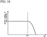
- the threshold Ne1 is the number of rotations of the engine 10 equivalent to the "predetermined speed" when the centrifugal clutch 8 outputs the rotational power of the crankshaft 16 to the outer clutch 25 when the rotating speed of the crankshaft 16 reaches the predetermined speed or higher. Determination regarding the number of rotations of the rotor 61 may be performed instead of the determination regarding the number of rotations of the engine 10.
- FIG. 18 is a view illustrating the relationship between changes in the number Ne of rotations of the engine 10 and the intensity of the assistance torque output from the ACG starter 60.
- the controller 70 performs powering control of the ACG starter 60 (motor generator) by making at least some coils among of a plurality of phases into a first state in which torque is generated in the rotor 60, until the number of rotations of the engine 10 (internal combustion engine) becomes equal to or greater than the predetermined number of rotations after an acceleration instruction is given to the vehicle in the stopped state or in a state in which the vehicle travels at low speed.
- the power generation unit related to the first embodiment performs powering control of a coil of at least one phase to output the assistance torque if there is an excessive charging amount regarding the charging rate of the battery 80 when a start instruction is given by a driver in the stopped state or in an extremely low-speed state, such as going slowly, of the motorcycle 1. Therefore, it is possible to shorten the time taken until the centrifugal clutch connects the crankshaft 16 and the outer clutch 25, and the acceleration ability at the time of starting moving in the motorcycle 1 can be improved.
- the acceleration ability at the time of starting moving in the motorcycle 1 can be improved.
- FIGS. 1 to 7 will be referred to and repeated description thereof will be omitted.
- FIG. 19 is a view illustrating a wiring structure centered on the ACG starter 60 of the power generation unit related to the third example useful for understanding the invention.
- the power generation unit related to the third example useful for understanding the invention generates, for example, a voltage (for example, a voltage slightly higher than 12 V) for charging the battery 80 using the U-phase coil after the engine is started 10, generates a voltage (for example, 24 V) for driving a head lamp HL using the V-phase coil, and changes the W-phase coil into the open state or the short-circuited state as in the first embodiment.
- the V-phase coil can generate a voltage different from the U-phase coil, for example, by making the number of times wound or switching timing different from those of the U-phase coil.
- illustration of the W-phase switching elements is omitted in FIG. 19 .
- a bypass capacitor C, a resistor R, and a light emitting diode (LED) that is a light emitter of the head lamp HL are connected between V-phase output terminals of the driving part related to the third example useful for understanding the invention.
- the power generation unit of the third example useful for understanding the invention is equipped with coils of a plurality of phases that are not connected to each other. Therefore, a plurality of voltages can be generated without adding the boosting converter or the like. As a result, the cost and the weight of the device can be reduced.
- the same effects as those of the first embodiment can be exhibited, and also a plurality of voltages can be generated without adding the boosting converter the like. As a result, the cost and the weight of the device can be reduced.
- the ACG starter 60 is controlled in three phases.
- the ACG starter may be controlled in two phases, four phases, five phases, six phases, or more.
- the power generation unit of the invention can be mounted on all types of vehicles, such as standard-sized automobiles and large-sized automobiles without being limited to the motorcycle.
Landscapes
- Engineering & Computer Science (AREA)
- Mechanical Engineering (AREA)
- Chemical & Material Sciences (AREA)
- Combustion & Propulsion (AREA)
- General Engineering & Computer Science (AREA)
- Power Engineering (AREA)
- Transportation (AREA)
- Control Of Eletrric Generators (AREA)
- Permanent Magnet Type Synchronous Machine (AREA)
- Windings For Motors And Generators (AREA)
- Control Of Motors That Do Not Use Commutators (AREA)
- Electric Propulsion And Braking For Vehicles (AREA)
- Control Of Vehicle Engines Or Engines For Specific Uses (AREA)
Claims (7)
- Stromerzeugungseinheit, die zusammen mit einem Verbrennungsmotor (10) an einem Fahrzeug (1) befestigt ist, der eine Antriebskraft zum Fortbewegen ausgibt und einen Rotor aufweist, der mit einer Rotationsausgangswelle des Verbrennungsmotors verbunden ist, wobei die Stromerzeugungseinheit umfasst:einen Motorgenerator (60), der durch den Rotor (61) gebildet wird, wobei der Rotor Magnete (62) und einen Stator (65) mit Spulen (66; 66a; 66b; 66c) aufweist, wobei die Spulen drei oder mehr Phasen begründen;ein Antriebssteuerungsteil (70), das konfiguriert ist, um eine Steuerung durchzuführen, um eine Spule von jeder Phase des Stators in einen ersten Zustand, in dem ein Drehmoment durch den Rotor erzeugt wird, einen zweiten Zustand, in dem beide Enden der Spule elektrisch freigegeben werden, oder einen dritten Zustand zu bringen, in dem beide Enden der Spule kurzgeschlossen werden;einen Beschleunigeröffnungssensor (76), der konfiguriert ist, um ein Beschleunigeröffnungssignal zu detektieren, das einen Beschleunigeröffnungsgrad (AC) des Fahrzeugs darstellt;einen Fahrzeuggeschwindigkeitssensor (78), der konfiguriert ist, um ein Geschwindigkeitssignal zu detektieren, das eine Fahrzeuggeschwindigkeit (V) des Fahrzeugs anzeigt;wobei die Spulen von jeder Phase nicht miteinander verbunden sind; undwobei das Antriebssteuerungsteil alle Spulen der drei oder mehr Phasen in den ersten Zustand bringt, wenn der Verbrennungsmotor durch Anlegen eines Drehmoments an die Rotationsausgangswelle gestartet wird;dadurch gekennzeichnet, dass:ein Kurbelwinkelsensor (79) konfiguriert ist, um ein Kurbelwinkelsignal zu detektieren, das einen Kurbelwinkel (θ) der Rotationsausgangswelle anzeigt;wenn der Motorgenerator veranlasst wird, elektrischen Strom unter Verwendung der Leistung des Verbrennungsmotors zu erzeugen, das Antriebssteuerungsteil einige Spulen unter den drei oder mehr Phasen in den zweiten Zustand bringt, wenn eine Anzahl von Rotationen des Rotors niedriger als eine vorbestimmte Anzahl von Rotationen ist, und einige Spulen unter den drei oder mehr Phasen in den dritten Zustand bringt, wenn eine Anzahl von Rotationen des Rotors gleich oder größer als eine vorbestimmte Anzahl von Rotationen ist;das Antriebssteuerungsteil eine Brückenschaltung aufweist, in der eine Vielzahl von Umschaltelementen die Spulen sandwichartig dazwischen einklemmen, wobei im zweiten Zustand alle der Vielzahl von Umschaltelementen der Brückenschaltung in einen OFF-Zustand gebracht werden und wobei im dritten Zustand alle Umschaltelemente auf einer negativen Elektrodenseite einer an die Stromerzeugungseinheit angeschlossenen Batterie (80) unter der Vielzahl von Umschaltelementen der Brückenschaltung in einen ON-Zustand gebracht werden und die Umschaltelemente auf einer positiven Elektrodenseite davon in einen OFF-Zustand gebracht werden;das Antriebssteuerungsteil bestimmt, ob eine Stromaufnahme (P) der Batterie gleich oder mehr als ein erster Schwellenwert (P1) ist, wenn die Beschleunigeröffnungsgrad-Eingabe vom Beschleunigeröffnungssensor gleich oder mehr als ein zweiter Schwellenwert (A2) ist, nachdem bestimmt wurde, dass eine Fahrzeuggeschwindigkeits-Eingabe vom Fahrzeuggeschwindigkeitssensor geringer als ein dritter Schwellenwert ist (V1);wenn bestimmt wird, dass die Stromaufnahme der Batterie gleich oder mehr als der erste Schwellenwert (P1) ist und wenn die Beschleunigeröffnungsgrad-Eingabe gleich oder mehr als der zweite Schwellenwert (A2) ist und die Fahrzeuggeschwindigkeits-Eingabe geringer als der dritte Schwellenwert (V1) ist, bestimmt die Antriebssteuerungseinheit, ob eine Anzahl von Rotationen (Ne) des Verbrennungsmotors gleich oder mehr als ein vierter Schwellenwert (Ne1) ist, basierend auf dem Kurbelwinkelsignal;wenn bestimmt wird, dass die Anzahl von Rotationen (Ne) des Verbrennungsmotors geringer als der vierte Schwellenwert (Ne1) ist, führt das Antriebssteuerungsteil eine Stromzufuhrsteuerung des Motorgenerators durch, indem mindestens einige der Spulen unter den drei oder mehr Phasen in den ersten Zustand gebracht werden und gibt ein Hilfsdrehmoment an den Motorgenerator aus; undwenn bestimmt wird, dass die Anzahl von Rotationen des Verbrennungsmotors gleich oder mehr als der vierte Schwellenwert (Ne1) wird, reduziert das Antriebssteuerungsteil das Hilfsdrehmoment mit Ansteigen der Anzahl von Rotationen des Verbrennungsmotors.
- Stromerzeugungseinheit nach Anspruch 1, wobei die Spulen der drei oder mehr Phasen eine unterschiedliche Windungsanzahl aufweisen und elektrischen Strom mit voneinander verschiedenen Stromerzeugungsspannungen erzeugen.
- Stromerzeugungseinheit nach Anspruch 1 oder 2, wobei das Antriebssteuerungsteil Umschaltzeitvorgaben für die Umschaltelemente von jeder Phase verschieden voneinander macht, wodurch die Spulen der drei oder mehr Phasen elektrischen Strom mit voneinander verschiedenen Stromerzeugungsspannungen erzeugen.
- Stromerzeugungseinheit nach Anspruch 2 oder 3, wobei elektrischer Strom, der von mindestens einer der Spulen unter den drei oder mehr Phasen erzeugt wird, zum Laden der Batterie verwendet wird und elektrischer Strom, der von mindestens einer anderen der Spulen der Vielzahl von Phasen für das Antreiben einer Beleuchtungsvorrichtung verwendet wird.
- Stromerzeugungseinheit nach einem der Ansprüche 1 bis 4, wobei das Antriebssteuerungsteil eine Stromzufuhrsteuerung des Motorgenerators durchführt, während es mindestens einige Spulen unter den drei oder mehr Phasen in den ersten Zustand macht, bis eine Anzahl von Rotationen des Verbrennungsmotors gleich oder größer als eine vorbestimmte Anzahl von Rotationen wird, nachdem dem Fahrzeug in einem angehaltenen Zustand oder in einem Zustand, in dem das Fahrzeug sich bei niedriger Geschwindigkeit fortbewegt, eine Beschleunigungsanweisung gegeben wurde.
- Stromerzeugungseinheit nach einem der Ansprüche 1 bis 5, wobei, wenn elektrischer Strom unter Verwendung einer Drehkraft einer Antriebsquelle erzeugt wird, das Antriebssteuerungsteil eine Spule einer Phase unter den in den drei Phasen angetriebenen Spulen in den ersten Zustand bringt und Spulen der zwei verbleibenden Phasen in den zweiten Zustand oder den dritten Zustand bringt.
- Verfahren zum Steuern eines Motorgenerators (60), der zusammen mit einem Verbrennungsmotor (10) an einem Fahrzeug (1) befestigt ist, der eine Antriebskraft zum Fortbewegen ausgibt und einen Rotor (61) aufweist, der mit einer Rotationsausgangswelle des Verbrennungsmotors verbunden ist, wobei der Motorgenerator durch den Rotor gebildet wird, wobei der Rotor Magnete (62) und einen Stator (65) mit Spulen (66; 66a; 66b; 66c) aufweist, wobei die Spulen drei oder mehr Phasen begründen, wobei die Spulen von jeder Phase nicht miteinander verbunden sind,
wobei, wenn eine Anzahl von Rotationen des Rotors in einem niedrigen Rotationsbereich liegt, einige Spulen unter den drei oder mehr Phasen in einen Zustand gebracht werden, in dem beide Enden einer Spule elektrisch freigegeben werden,
wobei, wenn eine Anzahl von Rotationen des Rotors in einem hohen Rotationsbereich liegt, einige Spulen unter den drei oder mehr Phasen in einen Zustand gebracht werden, in dem beide Enden einer Spule kurzgeschlossen werden,
wobei alle Spulen der drei oder mehr Phasen in den ersten Zustand gebracht werden, wenn der Verbrennungsmotor durch Anlegen von Drehmoment an die Rotationsausgabewelle gestartet wird,
wobei, wenn der Motorgenerator veranlasst wird, elektrischen Strom unter Verwendung der Leistung des Verbrennungsmotors zu erzeugen, einige Spulen unter den drei oder mehr Phasen in den zweiten Zustand gebracht werden, wenn eine Anzahl von Rotationen des Rotors niedriger als eine vorbestimmte Anzahl von Rotationen ist, und einige Spulen unter den drei oder mehr Phasen in den dritten Zustand gebracht werden, wenn eine Anzahl von Rotationen des Rotors gleich oder größer als eine vorbestimmte Anzahl von Rotationen ist,
wobei im zweiten Zustand alle einer Vielzahl von Umschaltelementen einer Brückenschaltung, in der die Spulen sandwichartig dazwischen eingeklemmt sind, in einen OFF-Zustand gebracht werden,
wobei im dritten Zustand alle Umschaltelemente auf einer negativen Elektrodenseite einer an die Stromerzeugungseinheit angeschlossenen Batterie unter der Vielzahl von Umschaltelementen der Brückenschaltung in einen ON-Zustand gebracht werden und die Umschaltelemente auf einer positiven Elektrodenseite davon in einen OFF-Zustand gebracht werden,
wobei bestimmt wird, ob eine Stromaufnahme (P) einer Batterie (80) gleich oder mehr als ein erster Schwellenwert (P1) ist, wenn ein Beschleunigeröffnungsgrad des Fahrzeugs gleich oder mehr als ein zweiter Schwellenwert (A2) in einem Zustand ist, wenn eine Geschwindigkeit des Fahrzeugs geringer als ein dritter Schwellenwert (V1) ist,
wobei, wenn bestimmt wird, dass die Stromaufnahme der Batterie gleich oder mehr als der erste Schwellenwert (P1) ist und wenn die Beschleunigeröffnungsgrad-Eingabe gleich oder mehr als der zweite Schwellenwert (A2) ist und die Fahrzeuggeschwindigkeits-Eingabe geringer als der dritte Schwellenwert (V1) ist, bestimmt wird, ob eine Anzahl von Rotationen (Ne) des Verbrennungsmotors gleich oder mehr als ein vierter Schwellenwert (Ne1) ist, basierend auf einem Kurbelwinkelsignal des Fahrzeugs,
wobei, wenn bestimmt wird, dass die Anzahl von Rotationen (Ne) des Verbrennungsmotors geringer als der vierte Schwellenwert (Ne1) ist, Stromzufuhrsteuerung des Motorgenerators durchgeführt wird, indem mindestens einige der Spulen unter den drei oder mehr Phasen in den ersten Zustand gebracht werden und ein Hilfsdrehmoment an den Motorgenerator ausgegeben wird, und
wobei, wenn bestimmt wird, dass die Anzahl von Rotationen des Verbrennungsmotors gleich oder mehr als der vierte Schwellenwert (Ne1) ist, das Hilfsdrehmoment mit Ansteigen der Anzahl von Rotationen des Verbrennungsmotors reduziert wird.
Applications Claiming Priority (2)
| Application Number | Priority Date | Filing Date | Title |
|---|---|---|---|
| JP2013058438 | 2013-03-21 | ||
| PCT/JP2013/083254 WO2014147904A1 (ja) | 2013-03-21 | 2013-12-11 | 発電電動ユニット、および発電電動機の制御方法 |
Publications (3)
| Publication Number | Publication Date |
|---|---|
| EP2978124A1 EP2978124A1 (de) | 2016-01-27 |
| EP2978124A4 EP2978124A4 (de) | 2016-12-21 |
| EP2978124B1 true EP2978124B1 (de) | 2019-02-06 |
Family
ID=51579615
Family Applications (1)
| Application Number | Title | Priority Date | Filing Date |
|---|---|---|---|
| EP13878969.8A Active EP2978124B1 (de) | 2013-03-21 | 2013-12-11 | Stromerzeugungseinheit und motorgeneratorsteuerungsverfahren |
Country Status (8)
| Country | Link |
|---|---|
| US (1) | US9709015B2 (de) |
| EP (1) | EP2978124B1 (de) |
| JP (1) | JP6038285B2 (de) |
| CN (1) | CN105052034B (de) |
| BR (1) | BR112015023575A8 (de) |
| MY (1) | MY172508A (de) |
| PH (1) | PH12015502179B1 (de) |
| WO (1) | WO2014147904A1 (de) |
Families Citing this family (11)
| Publication number | Priority date | Publication date | Assignee | Title |
|---|---|---|---|---|
| US9434385B2 (en) * | 2013-04-01 | 2016-09-06 | Toyota Jidosha Kabushiki Kaisha | Charge control device, vehicle control device, vehicle, charge control method and vehicle control method |
| JP6571548B2 (ja) * | 2016-01-22 | 2019-09-04 | 株式会社シマノ | 釣り用リール |
| CN106301123B (zh) * | 2016-10-20 | 2021-03-23 | 重庆乔麦科技有限公司 | 一种电动机发电电路 |
| CN106762313B (zh) * | 2017-02-08 | 2018-09-11 | 重庆望江摩托车制造有限公司 | 一种磁电机控制系统以及混合动力系统 |
| JP6568158B2 (ja) * | 2017-07-28 | 2019-08-28 | 株式会社Subaru | 車両用制御装置 |
| JP6781347B2 (ja) * | 2017-09-08 | 2020-11-04 | 本田技研工業株式会社 | 内燃機関 |
| CN112406570A (zh) * | 2019-08-22 | 2021-02-26 | 丰疆智能(深圳)有限公司 | 便携式车载补电装置、移动补电设备及其应用 |
| JP7486712B2 (ja) * | 2020-04-27 | 2024-05-20 | 株式会社Dgキャピタルグループ | 耐圧低減回路、回転機、および、インバータ電源装置 |
| US12409742B2 (en) * | 2022-12-08 | 2025-09-09 | Honda Motor Co., Ltd. | Electric vehicle |
| CN121219616A (zh) | 2023-07-11 | 2025-12-26 | 富士胶片株式会社 | 组合物、光学各向异性膜、化合物 |
| CN120575977B (zh) * | 2025-08-01 | 2025-11-25 | 泰州市凯华柴油发电机组有限公司 | 一种高效柴油发电机组 |
Family Cites Families (21)
| Publication number | Priority date | Publication date | Assignee | Title |
|---|---|---|---|---|
| GB190311299A (en) * | 1903-05-18 | 1904-05-18 | Ferranti Ltd | Improvements in Alternating Current Motors. |
| US3902073A (en) * | 1974-02-07 | 1975-08-26 | Gen Electric | Starter generator electrical system utilizing phase controlled rectifiers to drive a dynamoelectric machine as a brushless dc motor in the starter mode and to provide frequency conversion for a constant frequency output in the generating mode |
| JP3146743B2 (ja) * | 1993-04-12 | 2001-03-19 | トヨタ自動車株式会社 | リターダ装置 |
| JPH0795789A (ja) | 1993-09-20 | 1995-04-07 | Nippon Densan Corp | モータ |
| JPH07115704A (ja) * | 1993-10-14 | 1995-05-02 | Toyota Motor Corp | リターダ装置 |
| US5929611A (en) * | 1994-09-14 | 1999-07-27 | Coleman Powermate, Inc. | Light weight rotor and stator with multiple coil windings in thermal contact |
| JP3574146B2 (ja) | 1998-11-18 | 2004-10-06 | 三菱電機株式会社 | 車両用交流発電機の制御装置 |
| JP4427148B2 (ja) * | 2000-01-24 | 2010-03-03 | ヤンマー株式会社 | 発電装置 |
| US20050045392A1 (en) * | 2002-07-31 | 2005-03-03 | Maslov Boris A. | In-wheel electric motors |
| JP4410680B2 (ja) | 2002-10-04 | 2010-02-03 | 株式会社ミツバ | 始動発電システム及び始動発電機 |
| US7109687B2 (en) | 2002-11-11 | 2006-09-19 | Mitsubishi Denki Kabushiki Kaisha | Three-phase ac generator for vehicle |
| US6847147B2 (en) * | 2003-01-29 | 2005-01-25 | Wavecrest Laboratories, Llc | Dynamoelectric machine having windings that differ in wire gauge and number of winding turns |
| CN1328845C (zh) | 2003-12-18 | 2007-07-25 | 三菱电机株式会社 | 车辆用发电机的控制系统 |
| US7064526B2 (en) * | 2004-04-23 | 2006-06-20 | Astronics Advanced Electronic Systems Corp. | Fault tolerant architecture for permanent magnet starter generator subsystem |
| JP3968785B2 (ja) | 2004-05-18 | 2007-08-29 | セイコーエプソン株式会社 | 駆動回生制御システム |
| JP4670720B2 (ja) | 2006-04-21 | 2011-04-13 | 株式会社デンソー | 車両用発電制御装置 |
| JP5335509B2 (ja) * | 2009-03-25 | 2013-11-06 | 本田技研工業株式会社 | 回転電機 |
| JP5338544B2 (ja) | 2009-07-28 | 2013-11-13 | 株式会社ジェイテクト | 電動パワーステアリング装置 |
| JP4926227B2 (ja) | 2009-10-29 | 2012-05-09 | 三菱電機株式会社 | 電源装置 |
| JP5077389B2 (ja) | 2010-05-26 | 2012-11-21 | セイコーエプソン株式会社 | 電気機械装置 |
| JP5990005B2 (ja) * | 2012-02-16 | 2016-09-07 | 富士重工業株式会社 | ハイブリッド車両の電力供給装置 |
-
2013
- 2013-12-11 EP EP13878969.8A patent/EP2978124B1/de active Active
- 2013-12-11 CN CN201380074802.0A patent/CN105052034B/zh not_active Expired - Fee Related
- 2013-12-11 WO PCT/JP2013/083254 patent/WO2014147904A1/ja not_active Ceased
- 2013-12-11 JP JP2015506554A patent/JP6038285B2/ja not_active Expired - Fee Related
- 2013-12-11 BR BR112015023575A patent/BR112015023575A8/pt not_active Application Discontinuation
- 2013-12-11 US US14/777,650 patent/US9709015B2/en not_active Expired - Fee Related
- 2013-12-11 MY MYPI2015703266A patent/MY172508A/en unknown
-
2015
- 2015-09-17 PH PH12015502179A patent/PH12015502179B1/en unknown
Non-Patent Citations (1)
| Title |
|---|
| None * |
Also Published As
| Publication number | Publication date |
|---|---|
| WO2014147904A1 (ja) | 2014-09-25 |
| BR112015023575A8 (pt) | 2019-12-03 |
| EP2978124A1 (de) | 2016-01-27 |
| PH12015502179A1 (en) | 2016-01-25 |
| CN105052034B (zh) | 2018-06-29 |
| US20160102644A1 (en) | 2016-04-14 |
| CN105052034A (zh) | 2015-11-11 |
| EP2978124A4 (de) | 2016-12-21 |
| JP6038285B2 (ja) | 2016-12-07 |
| US9709015B2 (en) | 2017-07-18 |
| BR112015023575A2 (pt) | 2017-07-18 |
| JPWO2014147904A1 (ja) | 2017-02-16 |
| PH12015502179B1 (en) | 2016-01-25 |
| MY172508A (en) | 2019-11-28 |
Similar Documents
| Publication | Publication Date | Title |
|---|---|---|
| US9709015B2 (en) | Power generation unit, and motor generator control method | |
| EP2966761B1 (de) | Generatormotoreinheit, ausgangsleistungsmotor und fahrzeug | |
| CN101535611B (zh) | 车辆用混合发动机辅助系统 | |
| US8198836B2 (en) | Hybrid vehicle and method of controlling hybrid vehicle | |
| US9649945B2 (en) | Vehicle and method of controlling the vehicle | |
| KR102417370B1 (ko) | 마일드 하이브리드 차량의 엔진 시동 장치 및 방법 | |
| JP6802378B2 (ja) | ビークル | |
| JP2000203287A (ja) | 動力出力装置およびこれを備えるハイブリッド車 | |
| KR102394561B1 (ko) | 마일드 하이브리드 차량의 엔진 시동 장치 및 방법 | |
| US11052748B2 (en) | Controlling apparatus and controlling method of hybrid vehicle | |
| JP4755048B2 (ja) | ハイブリッド式自動二輪車 | |
| JP5174617B2 (ja) | 回転電機装置及びその制御装置 | |
| JPH09175225A (ja) | スタック脱出装置 | |
| JP2013119301A (ja) | ハイブリッド電気自動車のエンジン停止制御装置 | |
| WO2018131568A1 (ja) | 電力変換回路の制御装置、回転電機ユニット | |
| JP6665773B2 (ja) | 回転電機の回転上昇異常検出装置、回転電機ユニット | |
| JP2020128186A (ja) | ハイブリッドシステムの制御装置 | |
| CN111133188B (zh) | 车辆用控制装置 | |
| JP6749501B2 (ja) | 始動制御装置 | |
| JP2024074664A (ja) | エンジンの回転変動抑制装置 | |
| JP2013085373A (ja) | 省エネ走行機能付き自動車 |
Legal Events
| Date | Code | Title | Description |
|---|---|---|---|
| PUAI | Public reference made under article 153(3) epc to a published international application that has entered the european phase |
Free format text: ORIGINAL CODE: 0009012 |
|
| 17P | Request for examination filed |
Effective date: 20150929 |
|
| AK | Designated contracting states |
Kind code of ref document: A1 Designated state(s): AL AT BE BG CH CY CZ DE DK EE ES FI FR GB GR HR HU IE IS IT LI LT LU LV MC MK MT NL NO PL PT RO RS SE SI SK SM TR |
|
| AX | Request for extension of the european patent |
Extension state: BA ME |
|
| DAX | Request for extension of the european patent (deleted) | ||
| A4 | Supplementary search report drawn up and despatched |
Effective date: 20161118 |
|
| RIC1 | Information provided on ipc code assigned before grant |
Ipc: F02B 63/04 20060101ALI20161114BHEP Ipc: B60K 6/485 20071001ALI20161114BHEP Ipc: H02P 9/04 20060101AFI20161114BHEP Ipc: H02P 27/08 20060101ALI20161114BHEP Ipc: F02D 29/06 20060101ALI20161114BHEP Ipc: F02N 11/04 20060101ALI20161114BHEP Ipc: F02N 11/08 20060101ALI20161114BHEP Ipc: H02K 21/00 20060101ALI20161114BHEP Ipc: B60W 20/00 20160101ALI20161114BHEP Ipc: H02J 7/14 20060101ALI20161114BHEP Ipc: H02J 7/16 20060101ALI20161114BHEP Ipc: H02P 9/48 20060101ALI20161114BHEP Ipc: B60K 6/26 20071001ALI20161114BHEP Ipc: B60W 10/08 20060101ALI20161114BHEP |
|
| STAA | Information on the status of an ep patent application or granted ep patent |
Free format text: STATUS: EXAMINATION IS IN PROGRESS |
|
| 17Q | First examination report despatched |
Effective date: 20170927 |
|
| RIC1 | Information provided on ipc code assigned before grant |
Ipc: H02P 9/48 20060101ALI20180514BHEP Ipc: H02P 27/08 20060101ALI20180514BHEP Ipc: B60W 10/08 20060101ALI20180514BHEP Ipc: B60W 20/00 20160101ALI20180514BHEP Ipc: H02K 21/22 20060101ALI20180514BHEP Ipc: H02K 21/00 20060101ALI20180514BHEP Ipc: H02J 7/14 20060101ALI20180514BHEP Ipc: B60K 6/485 20071001ALI20180514BHEP Ipc: F02D 29/06 20060101ALI20180514BHEP Ipc: B60K 6/26 20071001ALI20180514BHEP Ipc: H02J 7/16 20060101ALI20180514BHEP Ipc: H02P 9/04 20060101AFI20180514BHEP Ipc: F02N 11/04 20060101ALI20180514BHEP Ipc: F02B 61/02 20060101ALI20180514BHEP Ipc: F02B 63/04 20060101ALI20180514BHEP Ipc: F02N 11/08 20060101ALI20180514BHEP |
|
| GRAP | Despatch of communication of intention to grant a patent |
Free format text: ORIGINAL CODE: EPIDOSNIGR1 |
|
| STAA | Information on the status of an ep patent application or granted ep patent |
Free format text: STATUS: GRANT OF PATENT IS INTENDED |
|
| INTG | Intention to grant announced |
Effective date: 20180716 |
|
| GRAS | Grant fee paid |
Free format text: ORIGINAL CODE: EPIDOSNIGR3 |
|
| GRAA | (expected) grant |
Free format text: ORIGINAL CODE: 0009210 |
|
| STAA | Information on the status of an ep patent application or granted ep patent |
Free format text: STATUS: THE PATENT HAS BEEN GRANTED |
|
| AK | Designated contracting states |
Kind code of ref document: B1 Designated state(s): AL AT BE BG CH CY CZ DE DK EE ES FI FR GB GR HR HU IE IS IT LI LT LU LV MC MK MT NL NO PL PT RO RS SE SI SK SM TR |
|
| REG | Reference to a national code |
Ref country code: GB Ref legal event code: FG4D |
|
| RIC2 | Information provided on ipc code assigned after grant |
Ipc: F02B 61/02 20060101ALI20180514BHEP Ipc: F02N 11/08 20060101ALI20180514BHEP Ipc: F02D 29/06 20060101ALI20180514BHEP Ipc: B60K 6/26 20071001ALI20180514BHEP Ipc: H02P 27/08 20060101ALI20180514BHEP Ipc: F02B 63/04 20060101ALI20180514BHEP Ipc: H02J 7/16 20060101ALI20180514BHEP Ipc: H02K 21/00 20060101ALI20180514BHEP Ipc: H02P 9/04 20060101AFI20180514BHEP Ipc: B60W 20/00 20160101ALI20180514BHEP Ipc: F02N 11/04 20060101ALI20180514BHEP Ipc: B60K 6/485 20071001ALI20180514BHEP Ipc: H02J 7/14 20060101ALI20180514BHEP Ipc: B60W 10/08 20060101ALI20180514BHEP Ipc: H02K 21/22 20060101ALI20180514BHEP Ipc: H02P 9/48 20060101ALI20180514BHEP |
|
| REG | Reference to a national code |
Ref country code: CH Ref legal event code: EP Ref country code: AT Ref legal event code: REF Ref document number: 1095490 Country of ref document: AT Kind code of ref document: T Effective date: 20190215 |
|
| REG | Reference to a national code |
Ref country code: IE Ref legal event code: FG4D |
|
| REG | Reference to a national code |
Ref country code: DE Ref legal event code: R096 Ref document number: 602013050660 Country of ref document: DE |
|
| REG | Reference to a national code |
Ref country code: NL Ref legal event code: MP Effective date: 20190206 |
|
| REG | Reference to a national code |
Ref country code: LT Ref legal event code: MG4D |
|
| PG25 | Lapsed in a contracting state [announced via postgrant information from national office to epo] |
Ref country code: LT Free format text: LAPSE BECAUSE OF FAILURE TO SUBMIT A TRANSLATION OF THE DESCRIPTION OR TO PAY THE FEE WITHIN THE PRESCRIBED TIME-LIMIT Effective date: 20190206 Ref country code: NL Free format text: LAPSE BECAUSE OF FAILURE TO SUBMIT A TRANSLATION OF THE DESCRIPTION OR TO PAY THE FEE WITHIN THE PRESCRIBED TIME-LIMIT Effective date: 20190206 Ref country code: FI Free format text: LAPSE BECAUSE OF FAILURE TO SUBMIT A TRANSLATION OF THE DESCRIPTION OR TO PAY THE FEE WITHIN THE PRESCRIBED TIME-LIMIT Effective date: 20190206 Ref country code: SE Free format text: LAPSE BECAUSE OF FAILURE TO SUBMIT A TRANSLATION OF THE DESCRIPTION OR TO PAY THE FEE WITHIN THE PRESCRIBED TIME-LIMIT Effective date: 20190206 Ref country code: PT Free format text: LAPSE BECAUSE OF FAILURE TO SUBMIT A TRANSLATION OF THE DESCRIPTION OR TO PAY THE FEE WITHIN THE PRESCRIBED TIME-LIMIT Effective date: 20190606 Ref country code: NO Free format text: LAPSE BECAUSE OF FAILURE TO SUBMIT A TRANSLATION OF THE DESCRIPTION OR TO PAY THE FEE WITHIN THE PRESCRIBED TIME-LIMIT Effective date: 20190506 |
|
| REG | Reference to a national code |
Ref country code: AT Ref legal event code: MK05 Ref document number: 1095490 Country of ref document: AT Kind code of ref document: T Effective date: 20190206 |
|
| PG25 | Lapsed in a contracting state [announced via postgrant information from national office to epo] |
Ref country code: HR Free format text: LAPSE BECAUSE OF FAILURE TO SUBMIT A TRANSLATION OF THE DESCRIPTION OR TO PAY THE FEE WITHIN THE PRESCRIBED TIME-LIMIT Effective date: 20190206 Ref country code: RS Free format text: LAPSE BECAUSE OF FAILURE TO SUBMIT A TRANSLATION OF THE DESCRIPTION OR TO PAY THE FEE WITHIN THE PRESCRIBED TIME-LIMIT Effective date: 20190206 Ref country code: BG Free format text: LAPSE BECAUSE OF FAILURE TO SUBMIT A TRANSLATION OF THE DESCRIPTION OR TO PAY THE FEE WITHIN THE PRESCRIBED TIME-LIMIT Effective date: 20190506 Ref country code: LV Free format text: LAPSE BECAUSE OF FAILURE TO SUBMIT A TRANSLATION OF THE DESCRIPTION OR TO PAY THE FEE WITHIN THE PRESCRIBED TIME-LIMIT Effective date: 20190206 Ref country code: GR Free format text: LAPSE BECAUSE OF FAILURE TO SUBMIT A TRANSLATION OF THE DESCRIPTION OR TO PAY THE FEE WITHIN THE PRESCRIBED TIME-LIMIT Effective date: 20190507 Ref country code: IS Free format text: LAPSE BECAUSE OF FAILURE TO SUBMIT A TRANSLATION OF THE DESCRIPTION OR TO PAY THE FEE WITHIN THE PRESCRIBED TIME-LIMIT Effective date: 20190606 |
|
| PG25 | Lapsed in a contracting state [announced via postgrant information from national office to epo] |
Ref country code: ES Free format text: LAPSE BECAUSE OF FAILURE TO SUBMIT A TRANSLATION OF THE DESCRIPTION OR TO PAY THE FEE WITHIN THE PRESCRIBED TIME-LIMIT Effective date: 20190206 Ref country code: AL Free format text: LAPSE BECAUSE OF FAILURE TO SUBMIT A TRANSLATION OF THE DESCRIPTION OR TO PAY THE FEE WITHIN THE PRESCRIBED TIME-LIMIT Effective date: 20190206 Ref country code: DK Free format text: LAPSE BECAUSE OF FAILURE TO SUBMIT A TRANSLATION OF THE DESCRIPTION OR TO PAY THE FEE WITHIN THE PRESCRIBED TIME-LIMIT Effective date: 20190206 Ref country code: EE Free format text: LAPSE BECAUSE OF FAILURE TO SUBMIT A TRANSLATION OF THE DESCRIPTION OR TO PAY THE FEE WITHIN THE PRESCRIBED TIME-LIMIT Effective date: 20190206 Ref country code: SK Free format text: LAPSE BECAUSE OF FAILURE TO SUBMIT A TRANSLATION OF THE DESCRIPTION OR TO PAY THE FEE WITHIN THE PRESCRIBED TIME-LIMIT Effective date: 20190206 Ref country code: RO Free format text: LAPSE BECAUSE OF FAILURE TO SUBMIT A TRANSLATION OF THE DESCRIPTION OR TO PAY THE FEE WITHIN THE PRESCRIBED TIME-LIMIT Effective date: 20190206 Ref country code: CZ Free format text: LAPSE BECAUSE OF FAILURE TO SUBMIT A TRANSLATION OF THE DESCRIPTION OR TO PAY THE FEE WITHIN THE PRESCRIBED TIME-LIMIT Effective date: 20190206 |
|
| REG | Reference to a national code |
Ref country code: DE Ref legal event code: R097 Ref document number: 602013050660 Country of ref document: DE |
|
| PG25 | Lapsed in a contracting state [announced via postgrant information from national office to epo] |
Ref country code: PL Free format text: LAPSE BECAUSE OF FAILURE TO SUBMIT A TRANSLATION OF THE DESCRIPTION OR TO PAY THE FEE WITHIN THE PRESCRIBED TIME-LIMIT Effective date: 20190206 Ref country code: SM Free format text: LAPSE BECAUSE OF FAILURE TO SUBMIT A TRANSLATION OF THE DESCRIPTION OR TO PAY THE FEE WITHIN THE PRESCRIBED TIME-LIMIT Effective date: 20190206 |
|
| REG | Reference to a national code |
Ref country code: DE Ref legal event code: R084 Ref document number: 602013050660 Country of ref document: DE |
|
| PLBE | No opposition filed within time limit |
Free format text: ORIGINAL CODE: 0009261 |
|
| STAA | Information on the status of an ep patent application or granted ep patent |
Free format text: STATUS: NO OPPOSITION FILED WITHIN TIME LIMIT |
|
| PG25 | Lapsed in a contracting state [announced via postgrant information from national office to epo] |
Ref country code: AT Free format text: LAPSE BECAUSE OF FAILURE TO SUBMIT A TRANSLATION OF THE DESCRIPTION OR TO PAY THE FEE WITHIN THE PRESCRIBED TIME-LIMIT Effective date: 20190206 |
|
| 26N | No opposition filed |
Effective date: 20191107 |
|
| PG25 | Lapsed in a contracting state [announced via postgrant information from national office to epo] |
Ref country code: SI Free format text: LAPSE BECAUSE OF FAILURE TO SUBMIT A TRANSLATION OF THE DESCRIPTION OR TO PAY THE FEE WITHIN THE PRESCRIBED TIME-LIMIT Effective date: 20190206 |
|
| PG25 | Lapsed in a contracting state [announced via postgrant information from national office to epo] |
Ref country code: TR Free format text: LAPSE BECAUSE OF FAILURE TO SUBMIT A TRANSLATION OF THE DESCRIPTION OR TO PAY THE FEE WITHIN THE PRESCRIBED TIME-LIMIT Effective date: 20190206 |
|
| REG | Reference to a national code |
Ref country code: CH Ref legal event code: PL |
|
| REG | Reference to a national code |
Ref country code: BE Ref legal event code: MM Effective date: 20191231 |
|
| PG25 | Lapsed in a contracting state [announced via postgrant information from national office to epo] |
Ref country code: MC Free format text: LAPSE BECAUSE OF FAILURE TO SUBMIT A TRANSLATION OF THE DESCRIPTION OR TO PAY THE FEE WITHIN THE PRESCRIBED TIME-LIMIT Effective date: 20190206 |
|
| GBPC | Gb: european patent ceased through non-payment of renewal fee |
Effective date: 20191211 |
|
| PG25 | Lapsed in a contracting state [announced via postgrant information from national office to epo] |
Ref country code: GB Free format text: LAPSE BECAUSE OF NON-PAYMENT OF DUE FEES Effective date: 20191211 Ref country code: IE Free format text: LAPSE BECAUSE OF NON-PAYMENT OF DUE FEES Effective date: 20191211 Ref country code: LU Free format text: LAPSE BECAUSE OF NON-PAYMENT OF DUE FEES Effective date: 20191211 Ref country code: FR Free format text: LAPSE BECAUSE OF NON-PAYMENT OF DUE FEES Effective date: 20191231 |
|
| PG25 | Lapsed in a contracting state [announced via postgrant information from national office to epo] |
Ref country code: BE Free format text: LAPSE BECAUSE OF NON-PAYMENT OF DUE FEES Effective date: 20191231 Ref country code: LI Free format text: LAPSE BECAUSE OF NON-PAYMENT OF DUE FEES Effective date: 20191231 Ref country code: CH Free format text: LAPSE BECAUSE OF NON-PAYMENT OF DUE FEES Effective date: 20191231 |
|
| PG25 | Lapsed in a contracting state [announced via postgrant information from national office to epo] |
Ref country code: CY Free format text: LAPSE BECAUSE OF FAILURE TO SUBMIT A TRANSLATION OF THE DESCRIPTION OR TO PAY THE FEE WITHIN THE PRESCRIBED TIME-LIMIT Effective date: 20190206 |
|
| PG25 | Lapsed in a contracting state [announced via postgrant information from national office to epo] |
Ref country code: MT Free format text: LAPSE BECAUSE OF FAILURE TO SUBMIT A TRANSLATION OF THE DESCRIPTION OR TO PAY THE FEE WITHIN THE PRESCRIBED TIME-LIMIT Effective date: 20190206 Ref country code: HU Free format text: LAPSE BECAUSE OF FAILURE TO SUBMIT A TRANSLATION OF THE DESCRIPTION OR TO PAY THE FEE WITHIN THE PRESCRIBED TIME-LIMIT; INVALID AB INITIO Effective date: 20131211 |
|
| PG25 | Lapsed in a contracting state [announced via postgrant information from national office to epo] |
Ref country code: MK Free format text: LAPSE BECAUSE OF FAILURE TO SUBMIT A TRANSLATION OF THE DESCRIPTION OR TO PAY THE FEE WITHIN THE PRESCRIBED TIME-LIMIT Effective date: 20190206 |
|
| PGFP | Annual fee paid to national office [announced via postgrant information from national office to epo] |
Ref country code: DE Payment date: 20221018 Year of fee payment: 10 |
|
| REG | Reference to a national code |
Ref country code: DE Ref legal event code: R119 Ref document number: 602013050660 Country of ref document: DE |
|
| PG25 | Lapsed in a contracting state [announced via postgrant information from national office to epo] |
Ref country code: DE Free format text: LAPSE BECAUSE OF NON-PAYMENT OF DUE FEES Effective date: 20240702 |
|
| PG25 | Lapsed in a contracting state [announced via postgrant information from national office to epo] |
Ref country code: DE Free format text: LAPSE BECAUSE OF NON-PAYMENT OF DUE FEES Effective date: 20240702 |
|
| PGFP | Annual fee paid to national office [announced via postgrant information from national office to epo] |
Ref country code: IT Payment date: 20251119 Year of fee payment: 13 |