EP2977505B1 - Machine d'épandage avec un dispositif auxiliaire de dépôt et d'alimentation d'articles vestimentaires plats sur une bande transporteuse - Google Patents
Machine d'épandage avec un dispositif auxiliaire de dépôt et d'alimentation d'articles vestimentaires plats sur une bande transporteuse Download PDFInfo
- Publication number
- EP2977505B1 EP2977505B1 EP14002548.7A EP14002548A EP2977505B1 EP 2977505 B1 EP2977505 B1 EP 2977505B1 EP 14002548 A EP14002548 A EP 14002548A EP 2977505 B1 EP2977505 B1 EP 2977505B1
- Authority
- EP
- European Patent Office
- Prior art keywords
- roof plate
- conveyor belt
- loading
- spoil
- flat clothing
- Prior art date
- Legal status (The legal status is an assumption and is not a legal conclusion. Google has not performed a legal analysis and makes no representation as to the accuracy of the status listed.)
- Active
Links
- 230000008021 deposition Effects 0.000 title claims description 10
- 238000000151 deposition Methods 0.000 claims description 11
- 238000007664 blowing Methods 0.000 claims description 8
- 230000001681 protective effect Effects 0.000 claims description 7
- 239000000463 material Substances 0.000 claims description 2
- 230000007704 transition Effects 0.000 description 3
- 239000004744 fabric Substances 0.000 description 2
- 230000006698 induction Effects 0.000 description 2
- 241000381592 Senegalia polyacantha Species 0.000 description 1
- 238000005452 bending Methods 0.000 description 1
- 230000002950 deficient Effects 0.000 description 1
- 238000010409 ironing Methods 0.000 description 1
- 238000000034 method Methods 0.000 description 1
- 230000000750 progressive effect Effects 0.000 description 1
Images


Classifications
-
- D—TEXTILES; PAPER
- D06—TREATMENT OF TEXTILES OR THE LIKE; LAUNDERING; FLEXIBLE MATERIALS NOT OTHERWISE PROVIDED FOR
- D06F—LAUNDERING, DRYING, IRONING, PRESSING OR FOLDING TEXTILE ARTICLES
- D06F67/00—Details of ironing machines provided for in groups D06F61/00, D06F63/00, or D06F65/00
- D06F67/04—Arrangements for feeding or spreading the linen
-
- D—TEXTILES; PAPER
- D06—TREATMENT OF TEXTILES OR THE LIKE; LAUNDERING; FLEXIBLE MATERIALS NOT OTHERWISE PROVIDED FOR
- D06F—LAUNDERING, DRYING, IRONING, PRESSING OR FOLDING TEXTILE ARTICLES
- D06F39/00—Details of washing machines not specific to a single type of machines covered by groups D06F9/00 - D06F27/00
-
- D—TEXTILES; PAPER
- D06—TREATMENT OF TEXTILES OR THE LIKE; LAUNDERING; FLEXIBLE MATERIALS NOT OTHERWISE PROVIDED FOR
- D06F—LAUNDERING, DRYING, IRONING, PRESSING OR FOLDING TEXTILE ARTICLES
- D06F67/00—Details of ironing machines provided for in groups D06F61/00, D06F63/00, or D06F65/00
- D06F67/10—Driving arrangements
-
- D—TEXTILES; PAPER
- D06—TREATMENT OF TEXTILES OR THE LIKE; LAUNDERING; FLEXIBLE MATERIALS NOT OTHERWISE PROVIDED FOR
- D06F—LAUNDERING, DRYING, IRONING, PRESSING OR FOLDING TEXTILE ARTICLES
- D06F95/00—Laundry systems or arrangements of apparatus or machines; Mobile laundries
- D06F95/002—Baskets or bags specially adapted for holding or transporting laundry; Supports therefor
-
- D—TEXTILES; PAPER
- D06—TREATMENT OF TEXTILES OR THE LIKE; LAUNDERING; FLEXIBLE MATERIALS NOT OTHERWISE PROVIDED FOR
- D06F—LAUNDERING, DRYING, IRONING, PRESSING OR FOLDING TEXTILE ARTICLES
- D06F45/00—Wringing machines with two or more co-operating rollers; Similar cold-smoothing apparatus
- D06F45/16—Details
- D06F45/28—Belt arrangements for guiding the linen between the rollers
Definitions
- the present invention relates to equipment for feeding laundry articles onto a conveyor system from which they are fed into subsequent processing machinery such as ironing machines, dryer, folding machines or the like.
- the machine for spreading out and loading flat clothing articles to a laundry processing unit includes an auxiliary device and two or more loading stations served by respective operators for spreading and loading large flat clothing articles, such as sheets or tablecloths, in a semiautomatic loading mode, and alternatively allows spreading and loading small flat clothing articles, such as napkins, pillowcases, cloths or tablecloths in a manual loading mode.
- US 472918 discloses a laundry feeding machine including a conveyor moving through a suction induction tunnel. Articles are held at their upper edges by an automatically releasing clamp to hang in front of the induction tunnel. Upon release of the clamp, a valving system is immediately actuated to apply suction to suck the article in to lie flat on the conveyor to be transported thereby.
- Figs. 10 and 11 show an embodiment particularly adapted to the handling of very wide articles such as bed sheets including a transverse suction chamber that is evacuated by a blower at either end. The conveyor belts pass immediately over the top of the suction chamber. A nip roller 92 is positioned close to the end of the tunnel 94 to provide an adequate air seal to insure that the flow of air from the tunnel inlet 96 is confined to flow into the suction chamber.
- US 5172502 describes a feeding aid for assisting in the feeding of laundry flatwork to laundry processing equipment such as an ironer.
- EP-A1-2584087 discloses a machine for spreading out and loading flat clothing articles onto a conveyor belt 30.
- the machine comprises a separator element 9 in the shape of a plate located above the conveyor belt 30 and the suction chamber.
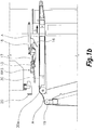
- This separator element is moved by driving means in coordination with the movements of a protective cover 11 (associated to spreading clamps) between a separating position (Fig. 9) corresponding with the free passage position of the protective cover 11, and a retracted position (Fig. 10) corresponding with the retaining position of the protective cover 11.
- a separating edge 9a of said separator element 9 is at a distance from the protective cover 11, which is located in its free passage position.
- This distance is sufficient to allow the passage of a first, second and third flat clothing articles A1, A2, A3 (A1 in Fig. 9) held and moved by the first or second spreading clamps 4a, 4b; 5a, 5b between their receiving and spread out positions but insufficient to allow the access of the hands of an operator to dangerous areas of the machine where the spreading clamps move at high speed.
- a machine for spreading out and loading flat clothing articles, such linen comprising a conveyor belt and an auxiliary device for deposition and feeding of flat clothing articles on said conveyor belt.
- the cited machines such the one disclosed in cited EP-A1-2584087 comprises according to a know structure, following basic parts:
- the auxiliary device of this invention is located in superposition to the conveyor belt loading end, extending transverse to said loading direction (D) and comprises:
- roof plate front end has a rounded profile providing a support that assists in the conveyance of the flat clothing article (A) towards the inside of referred wide opening provided by the roof plate while in said first position (RP1)
- the auxiliary device further includes additional blowing nozzles attached to the underside of said roof plate in an area close to its front end and oriented against said conveyor belt in the loading direction (D). In this manner the transfer of the article toward the surface of the conveyor belt is assisted and a better platting of the cloth article is assured.
- the device also provides a spoil articulated around an axis transverse to said loading direction (D) and defining a first position (SP1) in which a front end is separated from the conveyor belt and a second position (SP2) in which said spoil front end lies on the surface (or at a close distance) of a flat clothing article (A) deposited on and transferred by said conveyor belt flattening said clothing article (A).
- Driving means produce a rotation of said spoil between first (SP1) and second position (SP2) in coordination with the movements of said the roof plate so that when the spoil is in said first spoil position (SP1) roof plate is in said second position (RP2) and second spoil position (SP2) corresponds to said first roof plate position (RP1).
- said spoil is attached to an end of said roof plate remote from said front end and the roof plate and spoil are driven by same driving means or in the alternative the spoil is driven by an own driving means.
- Described roof plate is arranged on guides extending in the loading direction (D) allowing to take a third roof plate position (RP3) by sliding along said guides in which the auxiliary device is withdrawn from its location in superposition to said loading end of the conveyor belt and allowing then a manual loading of clothing articles onto the conveyor belt.
- RP3 roof plate position
- the cited third roof plate position (RP3) can be obtained by automatic driving means such as by a pneumatic cylinder or manually operated.
- part of the flat clothing deposition means further include a rotatable roll on which a part of the flat clothing material (A) lies before being transferred towards the conveyor belt, said rotatable roll being placed facing said conveyor belt loading end and at a distance thereof
- the roof plate of the auxiliary device includes a cover movable in extension (actuated by a driving means) to a fourth position (RP4) in which said roof plate front end lies over said rotatable roll providing a support for the flat clothing article (A) while a previous flat clothing article (A) is transported through said loading end of the conveyor belt.
- Figs. 1a to 6 show a machine for spreading out and loading flat clothing articles according to this invention.
- Said machine comprises a conveyor belt 30 having a considerably horizontal or slightly inclined upper section moving in a loading direction D, and several pairs of clamps 20 installed on corresponding carriages which are independently moved by driving means along a guide rail, transverse to said loading direction D, between a receiving position, in which said first spreading clamps 20 are adjacent to one another in a loading station, and in which it receives contiguous corners of flat clothing articles A loaded manually by operators, and a spread out position, in which the spreading clamps 20 are separated from one another and positioned facing the loading end of the conveyor belt 30, spreading the flat clothing article A.
- the auxiliary device of this invention helps in the transfer of said flat clothing article A from said position facing the loading end, and held by the spreading clamps 20, to an extended position with upper part of the flat clothing article A placed on the conveyor belt loading end 30a.
- the auxiliary device comprises a roof plate 13 located over the loading end 30a, and extended and articulated around a pivot axis 14 transverse to the loading direction D.
- Said pivot axis 14 allows said roof plate 13 to tilt between a first position ( Fig. 1a , 2 and 3 ), in which the roof plate 13 and its front end 13a are separated from the conveyor belt 30 leading end 30a, defining a wide opening for reception of the flat clothing articles A, and a second position ( Fig. 4 , 5 , 6 and 7 ), in which the roof plate 13 and its front end 13a are close to the conveyor belt 30 loading end 30a, allowing a passage of the flat clothing article A extended on said conveyor belt 30.
- the roof plate 13 includes a spoil 16 attached at a rear part of it, being said spoil 16 able to tilt around the pivot axis 14 between a first position ( Fig. 4 , 5 , 6 and 7 ), in which the spoil 16 and its front end 16a are separated from the conveyor belt 30, defining a wide opening, and a second position ( Fig. 1a , 2 and 3 ), in which the spoil 16 and its front end 16a are close to the conveyor belt 30, allowing a passage of the flat clothing article A on said conveyor belt 30.
- the roof plate 13 and the spoil 16 tilt around the pivot axis 14 at the same time because its attachment, and are configured to be on opposite positions, so when the roof plate 13 is on the first position, the spoil 16 is on the second position, and vice versa.
- the pivot axis 14 rotation is activated by driving means, as for example: an electric motor, a hydraulic piston, a servomotor, a lineal motor, an electromagnetic pusher, etc.
- driving means as for example: an electric motor, a hydraulic piston, a servomotor, a lineal motor, an electromagnetic pusher, etc.
- the roof plate 13, the pivot axis 14, the driving means, and the spoil 16 are linked to guides 17, along which all of them can slide.
- Said guides 17 are not parallel regarding the conveyor belt 30 upper said, so sliding said devices on said guides 17, the distance between the pivot axis 14 and the conveyor belt 30 is increased, and the auxiliary device is disabled allowing for a manual loading operation mode (shown on Fig. 1b ).
- This retired position of the roof plate 13 is the thereafter called third position.
- a driving means 18 illustrated as a piston, but any other driving mean is contemplated, as a lineal motor, a threaded shaft, or any other well known in the state of art.
- the manual operation of said sliding movement is also contemplated.
- deposition means include blowing nozzles 12 fixed to the protective cover 11 and arranged to blow an airflow on an upper part of the flat clothing article A comprised between the loading end 30a and the pair of spreading clamps 20,
- An additional blowing nozzle 15 is attached to the roof plate 13 placed on the lower side thereof, in an area close to the front end 13a, and directed against the conveyor belt 30 in the loading direction D, so that the airflow blown by said additional blowing nozzle 15, produces a further extension of the flat clothing article A loading edge, preventing undesirable folds of the flat clothing article A while in the transition movement to be placed against the conveyor end 30a.
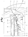
- a rotating roll 19 is placed confronted to the conveyor belt 30 front end 30a, existing a wide gap between them.
- said flat clothing article A is partially supported on said rotating roll 19, lying on it.
- the flat clothing article A pending portion is partially lifted and introduced on said wide gap, so the majority of the flat clothing article A weight is supported on the rotating roll 19, and the loading end 30a only supports the weight of the flat clothing article A portion introduced on said wide gap.
- a suction box 21 placed under the loading end 30a of the conveyor belt 30 is detailed, so that the flat clothing article A gripped by the spreading clamps 20 is pending in front of said suction box 21, and the suction produced supports partially the weight of the pending flat clothing article A.
- the same suction box 21 also helps the rotating roll 19 to introduce the flat clothing article A inside the wide gap.
- the spreading clamps 20 have spread out a flat clothing article A in front of the loading end 30a, being the roof plate 13 on the second position RP2, and being the spoil in the first position SP1.
- a second step illustrated on Fig. 3 the spreading clamps 20 release the flat clothing article A corners, and the airflow produced by the blow nozzle 12 and the additional blow nozzle 15 attached to roof plate 13 introduces and extends a portion of said flat clothing article A on the conveyor belt 30 loading end 30a.
- the rotating roll 19 introduces a portion of the flat clothing article A inside the wide gap, and the blow nozzle 12 produces an airflow which pushes the flat clothing article A upper segment against the loading end 30a.
- Fig. 4 is a third step showing the transition of the flat clothing article A towards the conveyor belt loading end 30a pushed by both nozzles 12 and 15.
- Fig. 5 the fourth step is illustrated, in which the roof plate 13 is rotated towards RP1 position regarding the pivot axis 14, by said driving means, and the front end 13a of said roof plate 13 is placed slightly above the conveyor belt 30, so that the additional blow nozzle 15 blows close to the flat clothing article A, ensuring its proper extension.
- a fifth step illustrated in Fig. 6
- the flat clothing article A lower edge has exceeded the rotating roll 19, and is pending in the wide gap
- the roof plate 13 stays on the first position
- a cover 13b is extended covering the wide gap, so that an additional flat clothing article A gripped on the spreading clamps 20, can be placed confronted to the loading end 30a of the conveyor belt 30 before the complete load operation of the preceding flat clothing article A, because the additional flat clothing article A cannot interfere with the flat clothing article A which is being loaded on the conveyor belt, thanks said cover extension, on which the additional flat clothing article A lies during said fifth step.
- the extension and retraction of said cover 13b can be achieved by a driving means, as a motor, a piston, a lineal motor, a magnetic pusher, etc.
- a driving means as a motor, a piston, a lineal motor, a magnetic pusher, etc.
- the fifth step is followed by the first step so that the operation cycle is restarted.
- the spoil 16 is placed on the second position SP2, ensuring that the lower edge of the previously loaded flat clothing article A has been perfectly extended on the conveyor belt, and preventing the lifting and bending of said lower edge due the airflow blown from the nozzles 12 and the additional blowing nozzles 15.
- the spoil shape is designed to deflect in the second position SP2 said airflow away from said lower edge.
- spoil 16 can be driven by own driving means.
- Fig. 7 a second embodiment is illustrated without rotating roll 19.
- another suction box 40 is foreseen to attack lower section of the flat clothing article A close to the loading end 30a, partially supporting the weight of said flat clothing article previous to its transfer onto the conveyor belt 30.
Landscapes
- Engineering & Computer Science (AREA)
- Textile Engineering (AREA)
- Treatment Of Fiber Materials (AREA)
- Intermediate Stations On Conveyors (AREA)
- Specific Conveyance Elements (AREA)
- Chain Conveyers (AREA)
Claims (9)
- Machine pour étaler et charger des articles vestimentaires plats, tel qu'un linge, cette machine comportant :un châssis supportant une bande d'amenée (30) se déplaçant dans le sens de chargement (D) et ayant une extrémité de chargement (30a) ;un dispositif auxiliaire pour déposer et alimenter des articles vestimentaires plats sur cette bande d'amenée (30) ;un capot protecteur (11) couvrant cette extrémité de chargement (30a) de la bande d'amenée (30) équipée de moyens d'aspiration ;deux ou plusieurs postes de chargement, chacun comprenant une paire de pinceurs d'étalement (20) entraînés par des moyens d'entraînement le long d'un rail de guidage transversal à ce sens de chargement (D) entre une position de réception , dans laquelle ces pinceurs d'étalement (20) sont adjacents les uns aux autres, dans un de ces postes de chargement pour attraper les coins contigus d'un article vestimentaire plat (A) chargé à la main par un opérateur et une position étalée, dans laquelle les pinceurs d'étalement (20) sont séparés les uns des autres en tenant cet article vestimentaire plat (A) par un de ses bords étalé et faisant face à cette extrémité de chargement (30a) de la bande d'amenée (30) ; etdes moyens déposants pour déposer, sur cette ouverture de pinceurs (20), une extrémité supérieure de cet article vestimentaire plat (A) sur la bande d'amenée (30) de cette position étalée des pinceurs d'étalement (20) à l'aide de buses de soufflage (12, 15) oùce dispositif auxiliaire est situé, superposé à l'extrémité de chargement (30a) de la bande d'amenée (30) s'étendant transversalement à ce sens de chargement (D) et comporte :une plaque de toit (13) située au-dessus de l'extrémité de chargement (30a) de la bande d'amenée (30), s'étendant transversalement au sens de chargement (D) et articulée autour d'un axe (14) transversalement au sens de chargement (D) en offrant une première position de plaque de toit (RP1), dans laquelle la plaque de toit (13) est séparée de la bande d'amenée (30) en définissant une large ouverture pour la réception d'un bord de cet article vestimentaire plat (A) et une deuxième position de plaque de toit (RP2) dans laquelle une extrémité frontale (13a) de la plaque de toit (13) repose près de l'extrémité de chargement (30a) de la bande d'amenée (30) en permettant le passage de l'article vestimentaire plat (A) étalé sur cette bande d'amenée (30) ;des moyens d'entraînement produisant une rotation de la plaque de toit (13) entre ces première (RP1) et deuxième (RP2) positions de plaque de toit en coordination avec le fonctionnement de ces moyens de déposition ;un volet (16) articulé autour d'un axe transversalement à ce sens de chargement (D) en offrant une première position de volet (SP1) dans laquelle une extrémité frontale (16a) de ce volet (16) est séparée de la bande d'amenée et une deuxième position du volet (SP2) dans laquelle cette extrémité frontale (16a) du volet (16) repose sur la surface d'un article vestimentaire plat (A) déposé dessus et transféré par cette bande d'amenée pour étaler cet article vestimentaire (A) ; etdes moyens d'entraînement produisant une rotation de ce volet (16) entre ces première (SP1) et deuxième (SP2) positions du volet en coordination avec les mouvements de cette plaque de toit (13) de sorte que lorsque le volet (16) se trouve dans cette première position de volet (SP1), la plaque de toit (13) se trouve dans cette deuxième position de plaque de toit (RP2) et lorsque le volet (16) se trouve dans cette deuxième position de volet (SP2) la plaque de toit (13) se trouve dans cette première position de plaque de toit (RP1).
- Machine conformément à la revendication 1 dans laquelle ce dispositif auxiliaire comporte par ailleurs des buses de soufflage (15) attachées à la partie du dessous de la plaque de toit (13) dans une région proche à cette extrémité frontale (13a) et orienté contre cette bande d'amenée (30) dans le sens de chargement (D).
- Machine conformément à la revendication 1 dans laquelle cette extrémité frontale (13a) de la plaque de toit (13) possède un profil arrondi offrant un support aidant au transport de l'article vestimentaire plat (A) vers l'intérieur de la large ouverture qu'offre la plaque de toit (13) tant qu'elle se trouve dans cette première position de plaque de toit (RP1).
- Machine conformément à la revendication 1 dans laquelle ce volet (16) est attaché à une extrémité de cette plaque de toit (13) éloignée de cette extrémité frontale (13a) et dans laquelle cette plaque de toit (13) et le volet (16) sont entraînés par les mêmes moyens d'entraînement.
- Machine conformément à la revendication 1 dans laquelle ce volet (16) est entraîné par un moyen d'entraînement propre.
- Machine conformément à la revendication 1 dans laquelle cette plaque de toit (13) est associée aux guidages (17) s'étendant dans le sens de chargement (D) en permettant une troisième position de plaque de toit (RP3) en glissant le long de ces guidages (17) dans lesquels le dispositif auxiliaire est retiré de son emplacement en superposition sur cette extrémité de chargement (30a) de la bande d'amenée (30).
- Machine conformément à la revendication 6 dans laquelle cette troisième position de plaque de toit (RP3) est obtenue par des moyens d'entraînement automatiques (18) ou fonctionnant à la main.
- Machine conformément à une quelconque des revendications précédentes dans laquelle ces moyens de déposition comprennent par ailleurs un rouleau rotatif (19) sur lequel une partie de l'article vestimentaire plat (A) repose avant d'être transféré vers la bande d'amenée (30), ce rouleau rotatif (19) étant placé faisant face à cette extrémité de chargement de la bande d'amenée (30a) et écarté de celle-ci et dans laquelle un capot (13b) de cette plaque de toit (13) est amovible, s'étendant à une quatrième position de plaque de toit (RP4) dans laquelle cette extrémité frontale (13a) de la plaque de toit (13) repose sur ce rouleau rotatif (19) en offrant un support à l'article vestimentaire plat (A) tandis qu'un article vestimentaire plat précédent (A) se déplace à travers cette extrémité de chargement (30a) de la bande d'amenée (30).
- Machine conformément à la revendication 8, dans laquelle ce capot (13b) peut être déplacé par un moyen d'entraînement.
Priority Applications (5)
| Application Number | Priority Date | Filing Date | Title |
|---|---|---|---|
| EP14002548.7A EP2977505B1 (fr) | 2014-07-24 | 2014-07-24 | Machine d'épandage avec un dispositif auxiliaire de dépôt et d'alimentation d'articles vestimentaires plats sur une bande transporteuse |
| ES14002548T ES2869964T3 (es) | 2014-07-24 | 2014-07-24 | Máquina para extender que comprende un dispositivo auxiliar para depositar y alimentar artículos textiles planos en una cinta transportadora |
| MX2015009559A MX366313B (es) | 2014-07-24 | 2015-07-23 | Maquina para extender y cargar articulos textiles planos con un dispositivo auxiliar para deposicion y alimentacion de articulos textiles planos sobre una cinta transportadora. |
| CN201510443022.XA CN105316910B (zh) | 2014-07-24 | 2015-07-24 | 用于储存和供给传送带上的平展衣物的辅助设备 |
| US14/808,136 US9657434B2 (en) | 2014-07-24 | 2015-07-24 | Machine for spreading out and loading flat clothing articles with an auxiliary device that deposits and feeds flat clothing articles on a conveyor belt |
Applications Claiming Priority (1)
| Application Number | Priority Date | Filing Date | Title |
|---|---|---|---|
| EP14002548.7A EP2977505B1 (fr) | 2014-07-24 | 2014-07-24 | Machine d'épandage avec un dispositif auxiliaire de dépôt et d'alimentation d'articles vestimentaires plats sur une bande transporteuse |
Publications (2)
| Publication Number | Publication Date |
|---|---|
| EP2977505A1 EP2977505A1 (fr) | 2016-01-27 |
| EP2977505B1 true EP2977505B1 (fr) | 2021-02-17 |
Family
ID=51224662
Family Applications (1)
| Application Number | Title | Priority Date | Filing Date |
|---|---|---|---|
| EP14002548.7A Active EP2977505B1 (fr) | 2014-07-24 | 2014-07-24 | Machine d'épandage avec un dispositif auxiliaire de dépôt et d'alimentation d'articles vestimentaires plats sur une bande transporteuse |
Country Status (5)
| Country | Link |
|---|---|
| US (1) | US9657434B2 (fr) |
| EP (1) | EP2977505B1 (fr) |
| CN (1) | CN105316910B (fr) |
| ES (1) | ES2869964T3 (fr) |
| MX (1) | MX366313B (fr) |
Families Citing this family (15)
| Publication number | Priority date | Publication date | Assignee | Title |
|---|---|---|---|---|
| CA3017244C (fr) | 2016-03-11 | 2023-10-10 | Jensen Denmark A/S | Appareil de reception, d'etalement/extension et d'aplanissement |
| CN105544167B (zh) * | 2016-03-15 | 2017-12-26 | 江苏海狮机械股份有限公司 | 滚槽熨平机 |
| CN106350979B (zh) * | 2016-12-06 | 2018-10-09 | 上海航星机械(集团)有限公司 | 用于辊槽烫衔接的气动控制机构及控制方法 |
| JP6621731B2 (ja) * | 2016-12-09 | 2019-12-18 | 株式会社プレックス | 布類展張装置 |
| JP6929138B2 (ja) * | 2017-06-06 | 2021-09-01 | 株式会社プレックス | 布類展張装置 |
| JP7064841B2 (ja) * | 2017-09-27 | 2022-05-11 | 株式会社プレックス | 布類展開装置 |
| CN108861748B (zh) * | 2018-07-13 | 2024-01-02 | 江苏海狮机械股份有限公司 | 展布机中的展布输送装置 |
| ES2899359T3 (es) * | 2018-12-05 | 2022-03-11 | Girbau Robotics | Dispositivo de alimentación y procedimiento para alimentar un artículo textil plano a un aparato de tratamiento de colada |
| JP7319180B2 (ja) | 2019-11-28 | 2023-08-01 | 株式会社プレックス | 布類展開装置 |
| DE102019135659A1 (de) * | 2019-11-28 | 2021-06-02 | Herbert Kannegiesser Gmbh | Verfahren und Vorrichtung zum Ergreifen rechteckiger textiler Gegenstände und/oder zum Zuführen rechtecktiger textiler Gegenstände zu einer Behandlungseinrichtung |
| CN115135828A (zh) | 2019-12-20 | 2022-09-30 | 高达机器公司 | 用于自动进料织物制品的机器 |
| CN111270468B (zh) * | 2020-03-18 | 2020-10-27 | 威马汽车科技集团有限公司 | 一种汽车垫整理机 |
| EP4158091A1 (fr) * | 2020-05-25 | 2023-04-05 | Jensen Denmark A/S | Appareil d'étalement de linge |
| JP2023526953A (ja) * | 2020-05-25 | 2023-06-26 | イェンセン・デンマーク・アクティーゼルスカブ | リネンスプレッダ装置 |
| CN114507960B (zh) * | 2021-10-30 | 2024-03-08 | 湖北欣柔卫生用品股份有限公司 | 一种无纺布染色后烘干定型一体机 |
Family Cites Families (16)
| Publication number | Priority date | Publication date | Assignee | Title |
|---|---|---|---|---|
| US472918A (en) | 1892-04-12 | Henry s | ||
| US1753040A (en) * | 1928-04-21 | 1930-04-01 | Beitler John | Safety attachment for wringers |
| DE1235252B (de) * | 1961-03-27 | 1967-03-02 | Gunnar Ivar Fredholm | Vorrichtung zum Ausbreiten und Zufuehren von Waeschestuecken od. dgl. zu einer Mangel |
| NL133144C (fr) * | 1965-05-21 | |||
| FR1550197A (fr) * | 1967-09-08 | 1968-12-20 | ||
| DD77950A1 (de) * | 1969-10-27 | 1970-12-05 | H WEIßMANN | Ausbreit- und zufuehvorrichtung fuer waeschestuecke, insbesondere vor einer mangel. |
| GB8402909D0 (en) | 1984-02-03 | 1984-03-07 | Weir Henry J | Laundry feeder |
| GB8813110D0 (en) * | 1988-06-03 | 1988-07-06 | Weir Henry J | Improvements in/relating to feed mechanisms for laundry articles |
| US5172502A (en) | 1991-06-21 | 1992-12-22 | Chicago Dryer Company | Flatwork feeder having flatwork sensing and clamping stations |
| CH696668A5 (de) * | 1996-03-08 | 2007-09-14 | Jensen Ag Burgdorf | Verfahren zum Zuführen von Wäschestücken zu einem Bearbeitungsgerät sowie Zuführvorrichtung. |
| FR2810347B1 (fr) * | 2000-06-16 | 2002-07-26 | Jean Michel Soc | Machine de blanchisserie industrielle dite "engageuse" |
| DK1683908T3 (da) * | 2003-10-10 | 2010-05-31 | Jean Michel Soc | Indretning og fremgangsmåde som anvendes til at indføre flade beklædningsdele i en vasketøjsbehandlingsenhed |
| DK176866B1 (da) * | 2006-05-19 | 2010-02-01 | Jensen Denmark As | Apparat til ilægning af tøjstykker |
| BE1018070A3 (nl) * | 2008-03-28 | 2010-04-06 | Lapauw Dominique | Invoerinrichting voor het invoeren van een te strijken stuk vlakgoed in een strijkeenheid en strijkinrichting voorzien van een dergelijke invoerinrichting. |
| ES2539424T3 (es) | 2011-10-17 | 2015-06-30 | Girbau Robotics | Máquina para extender y cargar artículos de ropa plana |
| WO2013057562A2 (fr) * | 2011-10-17 | 2013-04-25 | Girbau Robotics | Machine permettant de déplier et de charger des articles vestimentaires plats |
-
2014
- 2014-07-24 ES ES14002548T patent/ES2869964T3/es active Active
- 2014-07-24 EP EP14002548.7A patent/EP2977505B1/fr active Active
-
2015
- 2015-07-23 MX MX2015009559A patent/MX366313B/es active IP Right Grant
- 2015-07-24 CN CN201510443022.XA patent/CN105316910B/zh active Active
- 2015-07-24 US US14/808,136 patent/US9657434B2/en active Active
Non-Patent Citations (1)
| Title |
|---|
| None * |
Also Published As
| Publication number | Publication date |
|---|---|
| CN105316910B (zh) | 2019-01-22 |
| US9657434B2 (en) | 2017-05-23 |
| MX366313B (es) | 2019-07-04 |
| ES2869964T3 (es) | 2021-10-26 |
| US20160024706A1 (en) | 2016-01-28 |
| EP2977505A1 (fr) | 2016-01-27 |
| CN105316910A (zh) | 2016-02-10 |
| MX2015009559A (es) | 2016-01-25 |
Similar Documents
| Publication | Publication Date | Title |
|---|---|---|
| EP2977505B1 (fr) | Machine d'épandage avec un dispositif auxiliaire de dépôt et d'alimentation d'articles vestimentaires plats sur une bande transporteuse | |
| US9222213B2 (en) | Machine for spreading out and loading flat clothing articles | |
| US6826856B1 (en) | Laundry article spreader apparatus and method | |
| US10407822B2 (en) | Separator and stacker for textile articles | |
| EP3636824B1 (fr) | Dispositif d'étalement de tissu | |
| US20110142576A1 (en) | Method and apparatus for feeding a laundry article to a mangle or the like | |
| US20200291566A1 (en) | An apparatus for receiving, spreading/extending and flattening | |
| JP2018123466A (ja) | 布類展張装置 | |
| US7827709B2 (en) | Linen spreader apparatus and method | |
| JP2014517757A (ja) | 布片を送給するための方法及びフィーダ | |
| JP2013215361A (ja) | 布類展開装置 | |
| US6883258B2 (en) | Spreader apparatus and method for articles of laundry | |
| US8646594B2 (en) | Apparatus for automatic transfer of textile articles from a linking machine to a boarding machine | |
| EP2584087B1 (fr) | Machine pour étendre et charger des articles d'habillement plat | |
| EP2584088B1 (fr) | Machine pour étendre et charger de pièces de linge plats | |
| WO2018143128A1 (fr) | Appareil tendeur de tissu | |
| JP2016106892A (ja) | 方形状布類展開装置 | |
| EP2310565B1 (fr) | Machine presse-pantalon | |
| US20230013252A1 (en) | Machine for automatically feeding flatwork articles | |
| JP5961392B2 (ja) | 衣類投入機における袖吸引整形装置 | |
| JP2009279266A (ja) | 布類整形投入装置 |
Legal Events
| Date | Code | Title | Description |
|---|---|---|---|
| PUAI | Public reference made under article 153(3) epc to a published international application that has entered the european phase |
Free format text: ORIGINAL CODE: 0009012 |
|
| AK | Designated contracting states |
Kind code of ref document: A1 Designated state(s): AL AT BE BG CH CY CZ DE DK EE ES FI FR GB GR HR HU IE IS IT LI LT LU LV MC MK MT NL NO PL PT RO RS SE SI SK SM TR |
|
| AX | Request for extension of the european patent |
Extension state: BA ME |
|
| 17P | Request for examination filed |
Effective date: 20160609 |
|
| RBV | Designated contracting states (corrected) |
Designated state(s): AL AT BE BG CH CY CZ DE DK EE ES FI FR GB GR HR HU IE IS IT LI LT LU LV MC MK MT NL NO PL PT RO RS SE SI SK SM TR |
|
| RIC1 | Information provided on ipc code assigned before grant |
Ipc: D06F 67/04 20060101AFI20200824BHEP Ipc: D06F 45/28 20060101ALN20200824BHEP |
|
| GRAP | Despatch of communication of intention to grant a patent |
Free format text: ORIGINAL CODE: EPIDOSNIGR1 |
|
| STAA | Information on the status of an ep patent application or granted ep patent |
Free format text: STATUS: GRANT OF PATENT IS INTENDED |
|
| RIC1 | Information provided on ipc code assigned before grant |
Ipc: D06F 67/04 20060101AFI20200909BHEP Ipc: D06F 45/28 20060101ALN20200909BHEP |
|
| INTG | Intention to grant announced |
Effective date: 20201007 |
|
| RIN1 | Information on inventor provided before grant (corrected) |
Inventor name: DUPLOUY, SYLVAIN Inventor name: GARRONE, DOMINIQUE Inventor name: GORRIZ, MANUEL |
|
| GRAS | Grant fee paid |
Free format text: ORIGINAL CODE: EPIDOSNIGR3 |
|
| GRAA | (expected) grant |
Free format text: ORIGINAL CODE: 0009210 |
|
| STAA | Information on the status of an ep patent application or granted ep patent |
Free format text: STATUS: THE PATENT HAS BEEN GRANTED |
|
| AK | Designated contracting states |
Kind code of ref document: B1 Designated state(s): AL AT BE BG CH CY CZ DE DK EE ES FI FR GB GR HR HU IE IS IT LI LT LU LV MC MK MT NL NO PL PT RO RS SE SI SK SM TR |
|
| REG | Reference to a national code |
Ref country code: GB Ref legal event code: FG4D |
|
| REG | Reference to a national code |
Ref country code: CH Ref legal event code: EP |
|
| REG | Reference to a national code |
Ref country code: DE Ref legal event code: R096 Ref document number: 602014074759 Country of ref document: DE |
|
| REG | Reference to a national code |
Ref country code: AT Ref legal event code: REF Ref document number: 1361612 Country of ref document: AT Kind code of ref document: T Effective date: 20210315 |
|
| REG | Reference to a national code |
Ref country code: IE Ref legal event code: FG4D |
|
| REG | Reference to a national code |
Ref country code: LT Ref legal event code: MG9D |
|
| REG | Reference to a national code |
Ref country code: NL Ref legal event code: MP Effective date: 20210217 |
|
| PG25 | Lapsed in a contracting state [announced via postgrant information from national office to epo] |
Ref country code: NO Free format text: LAPSE BECAUSE OF FAILURE TO SUBMIT A TRANSLATION OF THE DESCRIPTION OR TO PAY THE FEE WITHIN THE PRESCRIBED TIME-LIMIT Effective date: 20210517 Ref country code: BG Free format text: LAPSE BECAUSE OF FAILURE TO SUBMIT A TRANSLATION OF THE DESCRIPTION OR TO PAY THE FEE WITHIN THE PRESCRIBED TIME-LIMIT Effective date: 20210517 Ref country code: HR Free format text: LAPSE BECAUSE OF FAILURE TO SUBMIT A TRANSLATION OF THE DESCRIPTION OR TO PAY THE FEE WITHIN THE PRESCRIBED TIME-LIMIT Effective date: 20210217 Ref country code: FI Free format text: LAPSE BECAUSE OF FAILURE TO SUBMIT A TRANSLATION OF THE DESCRIPTION OR TO PAY THE FEE WITHIN THE PRESCRIBED TIME-LIMIT Effective date: 20210217 Ref country code: GR Free format text: LAPSE BECAUSE OF FAILURE TO SUBMIT A TRANSLATION OF THE DESCRIPTION OR TO PAY THE FEE WITHIN THE PRESCRIBED TIME-LIMIT Effective date: 20210518 Ref country code: LT Free format text: LAPSE BECAUSE OF FAILURE TO SUBMIT A TRANSLATION OF THE DESCRIPTION OR TO PAY THE FEE WITHIN THE PRESCRIBED TIME-LIMIT Effective date: 20210217 Ref country code: PT Free format text: LAPSE BECAUSE OF FAILURE TO SUBMIT A TRANSLATION OF THE DESCRIPTION OR TO PAY THE FEE WITHIN THE PRESCRIBED TIME-LIMIT Effective date: 20210617 |
|
| REG | Reference to a national code |
Ref country code: AT Ref legal event code: MK05 Ref document number: 1361612 Country of ref document: AT Kind code of ref document: T Effective date: 20210217 |
|
| PG25 | Lapsed in a contracting state [announced via postgrant information from national office to epo] |
Ref country code: SE Free format text: LAPSE BECAUSE OF FAILURE TO SUBMIT A TRANSLATION OF THE DESCRIPTION OR TO PAY THE FEE WITHIN THE PRESCRIBED TIME-LIMIT Effective date: 20210217 Ref country code: NL Free format text: LAPSE BECAUSE OF FAILURE TO SUBMIT A TRANSLATION OF THE DESCRIPTION OR TO PAY THE FEE WITHIN THE PRESCRIBED TIME-LIMIT Effective date: 20210217 Ref country code: LV Free format text: LAPSE BECAUSE OF FAILURE TO SUBMIT A TRANSLATION OF THE DESCRIPTION OR TO PAY THE FEE WITHIN THE PRESCRIBED TIME-LIMIT Effective date: 20210217 Ref country code: RS Free format text: LAPSE BECAUSE OF FAILURE TO SUBMIT A TRANSLATION OF THE DESCRIPTION OR TO PAY THE FEE WITHIN THE PRESCRIBED TIME-LIMIT Effective date: 20210217 Ref country code: PL Free format text: LAPSE BECAUSE OF FAILURE TO SUBMIT A TRANSLATION OF THE DESCRIPTION OR TO PAY THE FEE WITHIN THE PRESCRIBED TIME-LIMIT Effective date: 20210217 |
|
| PG25 | Lapsed in a contracting state [announced via postgrant information from national office to epo] |
Ref country code: IS Free format text: LAPSE BECAUSE OF FAILURE TO SUBMIT A TRANSLATION OF THE DESCRIPTION OR TO PAY THE FEE WITHIN THE PRESCRIBED TIME-LIMIT Effective date: 20210617 |
|
| REG | Reference to a national code |
Ref country code: ES Ref legal event code: FG2A Ref document number: 2869964 Country of ref document: ES Kind code of ref document: T3 Effective date: 20211026 |
|
| PG25 | Lapsed in a contracting state [announced via postgrant information from national office to epo] |
Ref country code: SM Free format text: LAPSE BECAUSE OF FAILURE TO SUBMIT A TRANSLATION OF THE DESCRIPTION OR TO PAY THE FEE WITHIN THE PRESCRIBED TIME-LIMIT Effective date: 20210217 Ref country code: EE Free format text: LAPSE BECAUSE OF FAILURE TO SUBMIT A TRANSLATION OF THE DESCRIPTION OR TO PAY THE FEE WITHIN THE PRESCRIBED TIME-LIMIT Effective date: 20210217 Ref country code: CZ Free format text: LAPSE BECAUSE OF FAILURE TO SUBMIT A TRANSLATION OF THE DESCRIPTION OR TO PAY THE FEE WITHIN THE PRESCRIBED TIME-LIMIT Effective date: 20210217 Ref country code: AT Free format text: LAPSE BECAUSE OF FAILURE TO SUBMIT A TRANSLATION OF THE DESCRIPTION OR TO PAY THE FEE WITHIN THE PRESCRIBED TIME-LIMIT Effective date: 20210217 |
|
| REG | Reference to a national code |
Ref country code: DE Ref legal event code: R097 Ref document number: 602014074759 Country of ref document: DE |
|
| PG25 | Lapsed in a contracting state [announced via postgrant information from national office to epo] |
Ref country code: DK Free format text: LAPSE BECAUSE OF FAILURE TO SUBMIT A TRANSLATION OF THE DESCRIPTION OR TO PAY THE FEE WITHIN THE PRESCRIBED TIME-LIMIT Effective date: 20210217 Ref country code: SK Free format text: LAPSE BECAUSE OF FAILURE TO SUBMIT A TRANSLATION OF THE DESCRIPTION OR TO PAY THE FEE WITHIN THE PRESCRIBED TIME-LIMIT Effective date: 20210217 Ref country code: RO Free format text: LAPSE BECAUSE OF FAILURE TO SUBMIT A TRANSLATION OF THE DESCRIPTION OR TO PAY THE FEE WITHIN THE PRESCRIBED TIME-LIMIT Effective date: 20210217 |
|
| PLBE | No opposition filed within time limit |
Free format text: ORIGINAL CODE: 0009261 |
|
| STAA | Information on the status of an ep patent application or granted ep patent |
Free format text: STATUS: NO OPPOSITION FILED WITHIN TIME LIMIT |
|
| 26N | No opposition filed |
Effective date: 20211118 |
|
| PG25 | Lapsed in a contracting state [announced via postgrant information from national office to epo] |
Ref country code: AL Free format text: LAPSE BECAUSE OF FAILURE TO SUBMIT A TRANSLATION OF THE DESCRIPTION OR TO PAY THE FEE WITHIN THE PRESCRIBED TIME-LIMIT Effective date: 20210217 |
|
| REG | Reference to a national code |
Ref country code: DE Ref legal event code: R119 Ref document number: 602014074759 Country of ref document: DE |
|
| PG25 | Lapsed in a contracting state [announced via postgrant information from national office to epo] |
Ref country code: SI Free format text: LAPSE BECAUSE OF FAILURE TO SUBMIT A TRANSLATION OF THE DESCRIPTION OR TO PAY THE FEE WITHIN THE PRESCRIBED TIME-LIMIT Effective date: 20210217 |
|
| REG | Reference to a national code |
Ref country code: CH Ref legal event code: PL |
|
| PG25 | Lapsed in a contracting state [announced via postgrant information from national office to epo] |
Ref country code: MC Free format text: LAPSE BECAUSE OF FAILURE TO SUBMIT A TRANSLATION OF THE DESCRIPTION OR TO PAY THE FEE WITHIN THE PRESCRIBED TIME-LIMIT Effective date: 20210217 |
|
| REG | Reference to a national code |
Ref country code: BE Ref legal event code: MM Effective date: 20210731 |
|
| PG25 | Lapsed in a contracting state [announced via postgrant information from national office to epo] |
Ref country code: LI Free format text: LAPSE BECAUSE OF NON-PAYMENT OF DUE FEES Effective date: 20210731 Ref country code: IT Free format text: LAPSE BECAUSE OF FAILURE TO SUBMIT A TRANSLATION OF THE DESCRIPTION OR TO PAY THE FEE WITHIN THE PRESCRIBED TIME-LIMIT Effective date: 20210217 Ref country code: DE Free format text: LAPSE BECAUSE OF NON-PAYMENT OF DUE FEES Effective date: 20220201 Ref country code: CH Free format text: LAPSE BECAUSE OF NON-PAYMENT OF DUE FEES Effective date: 20210731 |
|
| PG25 | Lapsed in a contracting state [announced via postgrant information from national office to epo] |
Ref country code: IS Free format text: LAPSE BECAUSE OF FAILURE TO SUBMIT A TRANSLATION OF THE DESCRIPTION OR TO PAY THE FEE WITHIN THE PRESCRIBED TIME-LIMIT Effective date: 20210617 Ref country code: LU Free format text: LAPSE BECAUSE OF NON-PAYMENT OF DUE FEES Effective date: 20210724 |
|
| PG25 | Lapsed in a contracting state [announced via postgrant information from national office to epo] |
Ref country code: IE Free format text: LAPSE BECAUSE OF NON-PAYMENT OF DUE FEES Effective date: 20210724 Ref country code: BE Free format text: LAPSE BECAUSE OF NON-PAYMENT OF DUE FEES Effective date: 20210731 |
|
| PG25 | Lapsed in a contracting state [announced via postgrant information from national office to epo] |
Ref country code: HU Free format text: LAPSE BECAUSE OF FAILURE TO SUBMIT A TRANSLATION OF THE DESCRIPTION OR TO PAY THE FEE WITHIN THE PRESCRIBED TIME-LIMIT; INVALID AB INITIO Effective date: 20140724 |
|
| P01 | Opt-out of the competence of the unified patent court (upc) registered |
Effective date: 20230323 |
|
| PG25 | Lapsed in a contracting state [announced via postgrant information from national office to epo] |
Ref country code: CY Free format text: LAPSE BECAUSE OF FAILURE TO SUBMIT A TRANSLATION OF THE DESCRIPTION OR TO PAY THE FEE WITHIN THE PRESCRIBED TIME-LIMIT Effective date: 20210217 |
|
| PGFP | Annual fee paid to national office [announced via postgrant information from national office to epo] |
Ref country code: GB Payment date: 20230727 Year of fee payment: 10 Ref country code: ES Payment date: 20230831 Year of fee payment: 10 |
|
| PGFP | Annual fee paid to national office [announced via postgrant information from national office to epo] |
Ref country code: FR Payment date: 20230725 Year of fee payment: 10 |
|
| PG25 | Lapsed in a contracting state [announced via postgrant information from national office to epo] |
Ref country code: MK Free format text: LAPSE BECAUSE OF FAILURE TO SUBMIT A TRANSLATION OF THE DESCRIPTION OR TO PAY THE FEE WITHIN THE PRESCRIBED TIME-LIMIT Effective date: 20210217 |