EP2974689A1 - Anordnung zum sintern eines dentalwerkstücks - Google Patents
Anordnung zum sintern eines dentalwerkstücks Download PDFInfo
- Publication number
- EP2974689A1 EP2974689A1 EP15002103.8A EP15002103A EP2974689A1 EP 2974689 A1 EP2974689 A1 EP 2974689A1 EP 15002103 A EP15002103 A EP 15002103A EP 2974689 A1 EP2974689 A1 EP 2974689A1
- Authority
- EP
- European Patent Office
- Prior art keywords
- dental
- holding device
- dental workpiece
- workpiece
- arrangement according
- Prior art date
- Legal status (The legal status is an assumption and is not a legal conclusion. Google has not performed a legal analysis and makes no representation as to the accuracy of the status listed.)
- Granted
Links
Images




Classifications
-
- F—MECHANICAL ENGINEERING; LIGHTING; HEATING; WEAPONS; BLASTING
- F27—FURNACES; KILNS; OVENS; RETORTS
- F27B—FURNACES, KILNS, OVENS OR RETORTS IN GENERAL; OPEN SINTERING OR LIKE APPARATUS
- F27B5/00—Muffle furnaces; Retort furnaces; Other furnaces in which the charge is held completely isolated
- F27B5/04—Muffle furnaces; Retort furnaces; Other furnaces in which the charge is held completely isolated adapted for treating the charge in vacuum or special atmosphere
-
- A—HUMAN NECESSITIES
- A61—MEDICAL OR VETERINARY SCIENCE; HYGIENE
- A61C—DENTISTRY; APPARATUS OR METHODS FOR ORAL OR DENTAL HYGIENE
- A61C13/00—Dental prostheses; Making same
- A61C13/0003—Making bridge-work, inlays, implants or the like
- A61C13/0022—Blanks or green, unfinished dental restoration parts
-
- A—HUMAN NECESSITIES
- A61—MEDICAL OR VETERINARY SCIENCE; HYGIENE
- A61C—DENTISTRY; APPARATUS OR METHODS FOR ORAL OR DENTAL HYGIENE
- A61C13/00—Dental prostheses; Making same
- A61C13/12—Tools for fastening artificial teeth; Holders, clamps, or stands for artificial teeth
-
- B—PERFORMING OPERATIONS; TRANSPORTING
- B22—CASTING; POWDER METALLURGY
- B22F—WORKING METALLIC POWDER; MANUFACTURE OF ARTICLES FROM METALLIC POWDER; MAKING METALLIC POWDER; APPARATUS OR DEVICES SPECIALLY ADAPTED FOR METALLIC POWDER
- B22F10/00—Additive manufacturing of workpieces or articles from metallic powder
-
- B—PERFORMING OPERATIONS; TRANSPORTING
- B22—CASTING; POWDER METALLURGY
- B22F—WORKING METALLIC POWDER; MANUFACTURE OF ARTICLES FROM METALLIC POWDER; MAKING METALLIC POWDER; APPARATUS OR DEVICES SPECIALLY ADAPTED FOR METALLIC POWDER
- B22F3/00—Manufacture of workpieces or articles from metallic powder characterised by the manner of compacting or sintering; Apparatus specially adapted therefor ; Presses and furnaces
- B22F3/003—Apparatus, e.g. furnaces
-
- F—MECHANICAL ENGINEERING; LIGHTING; HEATING; WEAPONS; BLASTING
- F27—FURNACES; KILNS; OVENS; RETORTS
- F27B—FURNACES, KILNS, OVENS OR RETORTS IN GENERAL; OPEN SINTERING OR LIKE APPARATUS
- F27B17/00—Furnaces of a kind not covered by any of groups F27B1/00 - F27B15/00
- F27B17/02—Furnaces of a kind not covered by any of groups F27B1/00 - F27B15/00 specially designed for laboratory use
- F27B17/025—Furnaces of a kind not covered by any of groups F27B1/00 - F27B15/00 specially designed for laboratory use for dental workpieces
-
- F—MECHANICAL ENGINEERING; LIGHTING; HEATING; WEAPONS; BLASTING
- F27—FURNACES; KILNS; OVENS; RETORTS
- F27B—FURNACES, KILNS, OVENS OR RETORTS IN GENERAL; OPEN SINTERING OR LIKE APPARATUS
- F27B21/00—Open or uncovered sintering apparatus; Other heat-treatment apparatus of like construction
-
- F—MECHANICAL ENGINEERING; LIGHTING; HEATING; WEAPONS; BLASTING
- F27—FURNACES; KILNS; OVENS; RETORTS
- F27B—FURNACES, KILNS, OVENS OR RETORTS IN GENERAL; OPEN SINTERING OR LIKE APPARATUS
- F27B5/00—Muffle furnaces; Retort furnaces; Other furnaces in which the charge is held completely isolated
- F27B5/06—Details, accessories or equipment specially adapted for furnaces of these types
-
- F—MECHANICAL ENGINEERING; LIGHTING; HEATING; WEAPONS; BLASTING
- F27—FURNACES; KILNS; OVENS; RETORTS
- F27D—DETAILS OR ACCESSORIES OF FURNACES, KILNS, OVENS OR RETORTS, IN SO FAR AS THEY ARE OF KINDS OCCURRING IN MORE THAN ONE KIND OF FURNACE
- F27D3/00—Charging; Discharging; Manipulation of charge
- F27D3/12—Travelling or movable supports or containers for the charge
-
- F—MECHANICAL ENGINEERING; LIGHTING; HEATING; WEAPONS; BLASTING
- F27—FURNACES; KILNS; OVENS; RETORTS
- F27D—DETAILS OR ACCESSORIES OF FURNACES, KILNS, OVENS OR RETORTS, IN SO FAR AS THEY ARE OF KINDS OCCURRING IN MORE THAN ONE KIND OF FURNACE
- F27D5/00—Supports, screens or the like for the charge within the furnace
- F27D5/0043—Supports specially adapted for dental prosthesis
-
- A—HUMAN NECESSITIES
- A61—MEDICAL OR VETERINARY SCIENCE; HYGIENE
- A61C—DENTISTRY; APPARATUS OR METHODS FOR ORAL OR DENTAL HYGIENE
- A61C13/00—Dental prostheses; Making same
-
- A—HUMAN NECESSITIES
- A61—MEDICAL OR VETERINARY SCIENCE; HYGIENE
- A61C—DENTISTRY; APPARATUS OR METHODS FOR ORAL OR DENTAL HYGIENE
- A61C13/00—Dental prostheses; Making same
- A61C13/0003—Making bridge-work, inlays, implants or the like
-
- A—HUMAN NECESSITIES
- A61—MEDICAL OR VETERINARY SCIENCE; HYGIENE
- A61C—DENTISTRY; APPARATUS OR METHODS FOR ORAL OR DENTAL HYGIENE
- A61C13/00—Dental prostheses; Making same
- A61C13/20—Methods or devices for soldering, casting, moulding or melting
-
- A—HUMAN NECESSITIES
- A61—MEDICAL OR VETERINARY SCIENCE; HYGIENE
- A61F—FILTERS IMPLANTABLE INTO BLOOD VESSELS; PROSTHESES; DEVICES PROVIDING PATENCY TO, OR PREVENTING COLLAPSING OF, TUBULAR STRUCTURES OF THE BODY, e.g. STENTS; ORTHOPAEDIC, NURSING OR CONTRACEPTIVE DEVICES; FOMENTATION; TREATMENT OR PROTECTION OF EYES OR EARS; BANDAGES, DRESSINGS OR ABSORBENT PADS; FIRST-AID KITS
- A61F2/00—Filters implantable into blood vessels; Prostheses, i.e. artificial substitutes or replacements for parts of the body; Appliances for connecting them with the body; Devices providing patency to, or preventing collapsing of, tubular structures of the body, e.g. stents
- A61F2/02—Prostheses implantable into the body
- A61F2/28—Bones
-
- A—HUMAN NECESSITIES
- A61—MEDICAL OR VETERINARY SCIENCE; HYGIENE
- A61F—FILTERS IMPLANTABLE INTO BLOOD VESSELS; PROSTHESES; DEVICES PROVIDING PATENCY TO, OR PREVENTING COLLAPSING OF, TUBULAR STRUCTURES OF THE BODY, e.g. STENTS; ORTHOPAEDIC, NURSING OR CONTRACEPTIVE DEVICES; FOMENTATION; TREATMENT OR PROTECTION OF EYES OR EARS; BANDAGES, DRESSINGS OR ABSORBENT PADS; FIRST-AID KITS
- A61F2/00—Filters implantable into blood vessels; Prostheses, i.e. artificial substitutes or replacements for parts of the body; Appliances for connecting them with the body; Devices providing patency to, or preventing collapsing of, tubular structures of the body, e.g. stents
- A61F2/02—Prostheses implantable into the body
- A61F2/30—Joints
-
- B—PERFORMING OPERATIONS; TRANSPORTING
- B22—CASTING; POWDER METALLURGY
- B22F—WORKING METALLIC POWDER; MANUFACTURE OF ARTICLES FROM METALLIC POWDER; MAKING METALLIC POWDER; APPARATUS OR DEVICES SPECIALLY ADAPTED FOR METALLIC POWDER
- B22F3/00—Manufacture of workpieces or articles from metallic powder characterised by the manner of compacting or sintering; Apparatus specially adapted therefor ; Presses and furnaces
- B22F3/10—Sintering only
- B22F2003/1042—Sintering only with support for articles to be sintered
-
- B—PERFORMING OPERATIONS; TRANSPORTING
- B22—CASTING; POWDER METALLURGY
- B22F—WORKING METALLIC POWDER; MANUFACTURE OF ARTICLES FROM METALLIC POWDER; MAKING METALLIC POWDER; APPARATUS OR DEVICES SPECIALLY ADAPTED FOR METALLIC POWDER
- B22F3/00—Manufacture of workpieces or articles from metallic powder characterised by the manner of compacting or sintering; Apparatus specially adapted therefor ; Presses and furnaces
- B22F3/12—Both compacting and sintering
- B22F3/1208—Containers or coating used therefor
- B22F3/1258—Container manufacturing
- B22F3/1291—Solid insert eliminated after consolidation
-
- C—CHEMISTRY; METALLURGY
- C04—CEMENTS; CONCRETE; ARTIFICIAL STONE; CERAMICS; REFRACTORIES
- C04B—LIME, MAGNESIA; SLAG; CEMENTS; COMPOSITIONS THEREOF, e.g. MORTARS, CONCRETE OR LIKE BUILDING MATERIALS; ARTIFICIAL STONE; CERAMICS; REFRACTORIES; TREATMENT OF NATURAL STONE
- C04B35/00—Shaped ceramic products characterised by their composition; Ceramics compositions; Processing powders of inorganic compounds preparatory to the manufacturing of ceramic products
- C04B35/622—Forming processes; Processing powders of inorganic compounds preparatory to the manufacturing of ceramic products
- C04B35/64—Burning or sintering processes
-
- Y—GENERAL TAGGING OF NEW TECHNOLOGICAL DEVELOPMENTS; GENERAL TAGGING OF CROSS-SECTIONAL TECHNOLOGIES SPANNING OVER SEVERAL SECTIONS OF THE IPC; TECHNICAL SUBJECTS COVERED BY FORMER USPC CROSS-REFERENCE ART COLLECTIONS [XRACs] AND DIGESTS
- Y02—TECHNOLOGIES OR APPLICATIONS FOR MITIGATION OR ADAPTATION AGAINST CLIMATE CHANGE
- Y02P—CLIMATE CHANGE MITIGATION TECHNOLOGIES IN THE PRODUCTION OR PROCESSING OF GOODS
- Y02P10/00—Technologies related to metal processing
- Y02P10/25—Process efficiency
Definitions
- the invention relates to an arrangement for sintering a dental workpiece, with a machined dental workpiece and a holding device for the dental workpiece.
- the invention relates to a method for sintering a dental workpiece.
- the shows EP 1 154 969 B1 a method for dimensionally stable sintering of ceramic molded articles.
- a ceramic molded article may, for. B. be a dental prosthesis.
- the kiln is suspended by hooks, which hooks are made of refractory material, such as alumina.
- the suspension can also be done via movably mounted hooks.
- retaining pins are made of the same material as the kiln.
- the retaining pins are made of the same blank.
- a disadvantage of this method is that the suspension must be done via at least two hooks, which means a greater material and manufacturing costs.
- the center of gravity and the exact position of the dental workpiece must always be adjusted.
- the hooks always directly touch the dental workpiece or the molded article, which can leave unwanted impressions during sintering.
- the EP 1 868 961 B1 shows a device for dimensionally stable sintering of preformed ceramic dental articles, comprising a suspension system.
- This suspension system has a U-shaped swing. Again, it is disadvantageous that the suspension always takes place via at least two suspension elements. Again, here is disadvantageous that these rocking suspension elements lie directly on the ceramic dental article.
- This sintering foot is connected via small webs with the individual teeth.
- the standing or sintering foot serves primarily to prevent the teeth from coming into contact with the combustion chamber. Now, if this standing on the stand bridge is sintered, it can lead to a large delay; In the lateral areas of this delay is still relatively low, because there the gravity acts evenly on all members. In the upper area, however, it can happen during sintering that the individual members tilt away due to the thin connecting elements to the rear or front, so that an undesirable distortion occurs. That is, the fasteners are subjected to pressure, it comes to a shortening of the softening during sintering fasteners and thus almost inevitably to said tilting or to an undesirable bending.
- the object of the present invention is therefore to provide a comparison with the prior art improved arrangement or an improved method.
- no distortion should occur during sintering as possible the Material requirements are low and the surface of the dental workpiece is not affected.
- the dental workpiece corresponds in size to a dental construction with at least five, preferably at least eight, interconnected members (preferably each member at least partially corresponds to a tooth replacement of a single human tooth), the dental workpiece is suspended from the holding device and the dental workpiece via a formed in or on the dental workpiece, separate from the dental structure connecting piece with the holding device is connected or connectable.
- the delay is mainly prevented by the fact that the dental workpiece is suspended from the holding device.
- the impressions on the dental workpiece are mainly avoided by the separate from the dental construction connector.
- a large material wear is avoided by the fact that in large, at least five-unit dental constructions no complicated additional, integral with the dental workpiece holding components must be provided around the limbs of the dental workpiece around, but are only partially arranged on one side of the dental workpiece.
- By hanging the dental workpiece can be achieved in addition that the work is achieved evenly by heat radiation.
- the dental structure can in principle have quite long straight sections, the dental structure having at least five limbs.
- Each member corresponds to - at least partially - a dental prosthesis of a single human tooth.
- the individual limbs of the dental construction do not have to correspond to a complete tooth and thus not the dental construction to a complete dentition, whereby they do not have to have a direct tooth form until then. Rather, individual areas or members can indeed be designed so that it is built on this later and thereby the complete tooth shape of each individual member is created. This is the case, for example, with a so-called bridge. Therefore, these members must only correspond to areas of a later denture.
- the size of such a web corresponds to the size of a work on which then an at least five-membered dentures can be modeled.
- the bridge thus has a size in order to produce a dental prosthesis with at least five members in a later sequence.
- the dental structure is formed at least partially circular. That is, the dental structure already has a curvature that corresponds to a natural curvature or bend in the human dentition. If the dental structure has at least eight limbs, this curvature or bend is even more noticeable.
- the present invention brings particular advantages when the dental construction is completely circular.
- Completely circular means that the dental structure is at least 12- to 16-membered.
- the dental structure is designed as a bridge construction which is at least partially, preferably completely, circularly shaped, or as a bridge which is at least partially, preferably completely, circularly shaped.
- the dental workpiece has connecting webs and a base member, wherein the dental structure is connected via the connecting webs with the base member.
- the suspension is made via the base element.
- this can be achieved in that the connecting piece is formed in or on the base element.
- each member of the dental structure is connected via a respective connecting web with the base element.
- the dental workpiece can be produced particularly efficiently if the dental construction, the connecting webs and the base element are formed in one piece and form the machined dental workpiece. For a low material consumption is also provided that the base element plate-shaped is trained.
- the connecting webs are separated from the dental structure after sintering, preferably by a separating device.
- the basic design of the connector is arbitrary per se, as long as with this or this connector, the suspension of the dental workpiece on the fixture is made possible and this connector is formed separately from the dental structure.
- the connecting piece is formed as a recess or as a projection in the base element.
- the connecting piece lies on a central axis of the dental workpiece.
- This central axis corresponds to the left-right dividing plane of the human body and thus also of the human dentition.
- the suspension on this central axis also guarantees suspension in the center of gravity.
- the connecting piece is arranged or formed as possible in the center of the circular dental structure.
- a suspension element is preferably provided, wherein the dental workpiece is suspended from the holding device via the suspension element, preferably via a single suspension element.
- the suspension element is designed as a rope, as an adhesive or as a snap-in element. With regard to this suspension element, however, there are the following three preferred and different embodiments.
- the suspension element can be designed as a clamping device.
- this clamping device preferably two, jaws, which abut in clamping position on opposite sides of the base member.
- the connecting piece is formed by the surfaces of the base element contacting the clamping jaws. So it is no recess or no projection on the base element as a connector necessary.
- the suspension element is formed by the connecting piece designed as a projection and is releasably connected to a recess formed in the holding device, which forms a connection counterpart. In this variant, therefore, during production or milling of the dental workpiece, this projection must remain in the region of the base element, via which the dental workpiece is then suspended directly in the holding device.
- the reverse construction is possible, after which the suspension element is formed as separate from the dental workpiece connecting counterpart, wherein the suspension member is detachably connected via the formed as a recess in the dental workpiece connecting piece with the dental workpiece.
- the suspension element is designed as a projection formed on the holding device and integral with the holding device.
- a total of only two parts - namely the dental workpiece and the holding device - are provided, wherein just the suspension element is formed integrally with the holding device.
- the suspension element is formed separately from the holding device and is movably mounted on the holding device.
- This suspension element can be made of any material (or of a material mixture), which withstands the temperature stresses during sintering.
- ceramic, metal or metal alloys are used.
- the entire arrangement consists of three separate components, namely the dental workpiece, the holding device and the separate suspension element.
- the suspension element is movably mounted on a recess formed in the holding device, preferably oriented horizontally.
- the, preferably bolt-shaped, suspension element protrudes with suspended dental workpiece both through the recess in the holding device and through the, the connector forming recess in the base element of the dental workpiece.
- the design of the holding device is also arbitrary, as long as a secure hanging of the dental workpiece is guaranteed.
- a simple construction provides that the holding device has two lateral, preferably disk-shaped, uprights and a carrier connecting the uprights.
- the holding device can in principle consist of any material which withstands the sintering temperatures.
- the holding device consists essentially of alumina or alumina foam.
- the dental workpiece can be made of zircon or other sinterable materials.
- the dental workpiece consists essentially of dental metals, such as a chromium-cobalt alloy. Since with dental metals the risk of distortion is even greater than with zircon or other sinterable materials, the present invention is particularly well suited for such dental metal work.
- the arrangement has a sintering furnace, wherein the holding device, together with the dental workpiece suspended thereon, is arranged during sintering in a furnace chamber of the sintering furnace.
- a closable, tubular housing is preferably provided, wherein the holding device together with the dental workpiece suspended therefrom is arranged in the housing during sintering in the furnace chamber of the sintering furnace.
- the sintering furnace has a tower forming a door of the sintering furnace, wherein the housing projects through the attachment at least partially into the furnace chamber.
- a device is preferably provided for generating a vacuum in the housing or for introducing protective gas into the housing.
- the object of the present invention is also achieved by a method according to claim 15.
- the steps according to the invention are therefore processing of the dental workpiece so that the dental workpiece has a dental construction with at least eight links connected to one another (each limb being at least partially a denture of a single human tooth), suspending the dental workpiece on the holding device by connecting the dental workpiece to the holding device via a connector formed in or on the dental workpiece, separate from the dental structure, and sintered, preferably oxygen-free sintered, of the dental workpiece suspended from the holding device.
- the Holding device 3 in this case comprises two lateral, disc-shaped pillars 12, which are connected via a carrier 13.
- This holding device 3 is formed in one piece and consists of a hard alumina foam.
- the dental workpiece 2 z. B. zircon or dental metal.
- This dental workpiece 2 machined in a machining or milling device has an at least five-membered, preferably at least eight-membered, dental construction 4.
- the individual members 5 of this circular dental structure 4 are each connected via connecting webs 7 with a plate-shaped base element 8.
- the connecting piece 6 is formed in the form of a recess in the base element 8.
- the bolt-shaped suspension element 9 - which forms the connection counterpart 10 to the connector 6 - the dental workpiece 2 is suspended on the holding device 3, wherein the suspension element 9 is detachably connected in a recess 11 on the holding device 3.
- the suspension element 9 thus connects the dental workpiece 2 with the holding device 3.
- the arrangement 1 consists of the three components dental workpiece 2, holding device 3 and suspension element.
- the suspension can also be configured differently.
- the connector 6 may be formed as a projection and directly into the recess 11 - which then forms the connection counterpart 10 - engage in the holding device 3.
- the suspension element 9 is integrally formed with the holding device 3 and thus protrudes from this and then the dental workpiece 2 is suspended on this suspension element 9 via the formed as a recess connecting piece 6.
- Fig. 3 shows a cap 16, which forms a door of a sintering furnace 14. At this essay 16 door handles 21 are mounted. In Fig. 3a the front part of this article 16 with the insertion opening 19 can be seen. From this insertion opening 19 also leads the connection 18 away, via which a connection with the only indicated by dashed lines device 17 for generating a vacuum or for the introduction of inert gas is connected.
- Fig. 4 shows a front view of the essay 16, wherein here again the terminal 18 and the door handles 21 can be seen.
- Fig. 5 shows a section through the attachment 16, wherein the detachably held in the article 16, tubular housing 15 is shown.
- This housing 15 forms a vacuum sinter tube.
- the housing 15 can be closed by the closure lid 20, whereby after introduction of a protective gas or after generation of a vacuum via the connection 18, the dental workpiece 2 arranged in the housing 15 is sintered in the sintering furnace 14.
- the furnace housing 22 of the sintering furnace 14 is in Fig. 5 indicated only by dashed lines. However, it is readily apparent that the dental workpiece suspended on the holding device 3 is arranged in the oven space R (combustion chamber) of this sintering oven 14.
- Fig. 5a is also well visible that the outer contour of the holding device 3 and in particular the disc-shaped post 12 is adapted to the inner contour of the tubular housing 15, whereby a secure hold is given.
- the dental workpiece 2 can also be sintered directly in the furnace chamber R - ie without vacuum sintering tube or housing 15. Then the sintering furnace 14 is closed instead of the attachment 16 with a normal door.
- the holding device 3 of course, also have a different shape with a flat standing surface.
- the recess 11 is formed in the holding device 3 as an elongated recess on the upper side of the carrier 13 of the holding device 3.
- the suspension element 9 is located in this depression.
- the connecting piece 6 is formed as a recess in the uppermost region of the plate-shaped base element 8.
- the suspension element 9 holds the dental workpiece 2 on the holding device 3.
- the uprights 12 are annular in design and formed with a flattened standing area.
- Fig. 7a, 7b and 7c show different views of an arrangement 1 with a relatively small, in this case five-membered dental structure 4, which is connected via connecting webs 7 with a horizontally oriented base element 8.
- the suspension element 9 has retaining projections 23 on which the base element 8 rests. In this case, these support surfaces of the base element 8 form the connecting piece 6. As in the previous variant, the suspension element 9 is again suspended on the holding device 3 in a recess 11 formed as an elongated depression. It is also possible for a plurality of such relatively small dental workpieces 2 to be hung on a holding device 3 via a suspension element which has a plurality of retaining projections 23 arranged next to one another or via a plurality of separate suspension elements 9.
- the suspension element 9 is formed by a clamping device.
- This clamping device has two clamping jaws 24, which is inserted from above into a recess 11 provided with oblique side surfaces in the carrier 13. As a result, the clamping jaws 24 are moved relative to one another, whereby the base element 8 of the dental workpiece 2 located between the clamping jaws 24 is clamped in the clamping device and thereby on the holding device 3 is hung.
- the connecting piece 6 is formed in this case by the voltage applied to the inner sides of the clamping jaws 24 surface portions of the base member 8.
- Fig. 9a and 9b show different views of a dental workpiece 2, in which the dental structure 4 is not designed as a substantially complete dentures (as in all previous schematic figures) but as a web.
- This web can be used for example via a clip connection or other methods known to the dental technician for attaching the actual dental prosthesis assembly.
- a dental workpiece 2 can be suspended as described on a holding device 3.
Landscapes
- Health & Medical Sciences (AREA)
- Engineering & Computer Science (AREA)
- Mechanical Engineering (AREA)
- Oral & Maxillofacial Surgery (AREA)
- General Engineering & Computer Science (AREA)
- Veterinary Medicine (AREA)
- General Health & Medical Sciences (AREA)
- Public Health (AREA)
- Animal Behavior & Ethology (AREA)
- Life Sciences & Earth Sciences (AREA)
- Epidemiology (AREA)
- Dentistry (AREA)
- Manufacturing & Machinery (AREA)
- Clinical Laboratory Science (AREA)
- Chemical & Material Sciences (AREA)
- Materials Engineering (AREA)
- Dental Tools And Instruments Or Auxiliary Dental Instruments (AREA)
- Dental Prosthetics (AREA)
Abstract
Description
- Die Erfindung betrifft eine Anordnung zum Sintern eines Dentalwerkstücks, mit einem bearbeiteten Dentalwerkstück und einer Haltevorrichtung für das Dentalwerkstück. Zudem betrifft die Erfindung ein Verfahren zum Sintern eines Dentalwerkstücks.
- Bei der Herstellung von Dentalwerkstücken, z. B. aus Sintermetallteilen, besteht eine große Herausforderung in der Sinterung der Grünlinge. Bei komplexeren Arbeiten, besonders im Dentalbereich, ist es von großer Wichtigkeit, dass es beim Sintern nicht zu einem unerwünschten Verzug der Arbeiten kommt. So war es bis jetzt nur möglich, kleinere Brückenarbeiten ohne problematischen Verzug herzustellen.
- Aus dem Stand der Technik sind auch bereits diverse Möglichkeiten bekannt, um den Sintervorgang zu verbessern, jedoch weisen sämtliche bekannte Methoden Nachteile auf.
- Beispielsweise zeigt die
EP 1 154 969 B1 ein Verfahren zum dimensionstreuen Sintern von keramischen Formgegenständen. Ein solcher keramischer Formgegenstand kann z. B. ein Zahnersatzteil sein. In dieser Schrift ist angeführt, dass das Brenngut über Haken aufgehängt wird, wobei diese Haken aus feuerfestem Material, beispielsweise Aluminiumoxid, bestehen. Die Aufhängung kann auch über beweglich angebrachte Haken erfolgen. Weiters ist angeführt, dass Haltestifte aus dem gleichen Material wie das Brenngut bestehen. Z. B. sind die Haltestifte aus dem gleichen Rohling gefertigt. Nachteilig bei diesem Verfahren ist, dass das Aufhängen über zumindest zwei Haken erfolgen muss, was einen größeren Material- und Herstellungsaufwand bedeutet. Weiters muss immer der Schwerpunkt und die genaue Lage des Dentalwerkstücks eingestellt werden. Zudem berühren die Haken immer direkt das Dentalwerkstück bzw. den Formgegenstand, was beim Sintern ungewünschte Abdrücke hinterlassen kann. - Die
EP 1 868 961 B1 zeigt eine Einrichtung für dimensionsstabiles Sintern von vorgeformten keramischen Dentalartikeln, aufweisend ein Aufhängsystem. Dieses Aufhängsystem weist eine U-förmige Schaukel auf. Auch hierbei ist nachteilig, dass das Aufhängen immer über mindestens zwei Aufhängelemente erfolgt. Auch hier ist nachteilig, dass diese schaukelförmigen Aufhängelemente direkt am keramischen Dentalartikel anliegen. - Weiters kann noch auf die
EP 2 014 254 A1 verwiesen werden, welche eine zirkuläre Brücke (bridge structure) zeigt, die mit einem Halteteil (support body) über Verbindungselemente (retaining sections) verbunden ist. Z. B. ausFig. 6 dieser Schrift geht hervor, dass das Halteteil, die Verbindungselemente und die Brückenkonstruktion einstückig ausgeführt sind. Eine derartige Konstruktion ist allerdings nur bei kleinen, wie inFig. 6 dargestellt, dreigliedrigen Dentalwerkstücken sinnvoll, wobei auch bereits bei diesen recht kleinen Dentalwerkstücken sehr viel an Material für das das Dentalwerkstück umgebende Halteteil verwendet werden muss. Dies bringt einen erheblichen Materialverbrauch und ist sehr aufwendig. Aus diesem Grund ist in derEP 2 014 254 A1 auch ein weiteres Ausführungsbeispiel (sieheFig. 12 bis 18 ) dargelegt, bei welchem eine recht große vielgliedrige zirkuläre Brücke dargestellt ist. Diese Brücke wird an einem stehenden Halteteil in Form eines Sinterfußes angebracht. Dieser Sinterfuß ist über kleine Stege mit den einzelnen Zähnen verbunden. Der Stand- bzw. Sinterfuß dient vornehmlich dazu, dass die Zähne nicht mit der Brennkammer in Kontakt kommen. Wenn nun diese auf dem Standfuß stehende Brücke gesintert wird, kann es zu einem großen Verzug kommen; In den seitlichen Bereichen ist dieser Verzug noch relativ gering, da dort die Schwerkraft gleichmäßig auf alle Glieder wirkt. Im oberen Bereich kann es beim Sintern allerdings dazu kommen, dass die einzelnen Glieder aufgrund der dünnen Verbindungselemente nach hinten oder vorne wegkippen, sodass ein ungewünschter Verzug entsteht. Das heißt, werden die Verbindungselemente auf Druck beansprucht, kommt es zu einer Verkürzung der beim Sintern weich werdenden Verbindungselemente und somit fast unweigerlich zur besagten Verkippung bzw. zu einer ungewünschten Verbiegung. - Dieselben Nachteile wie bei der letztgenannten Schrift sind auch bei der
DE 10 2009 044 461 A1 gegeben, welche ein Verfahren zum Dimensionstreuen Sintern eines Formteils zeigt. - Die Aufgabe der vorliegenden Erfindung besteht daher darin, eine gegenüber dem Stand der Technik verbesserte Anordnung bzw. ein verbessertes Verfahren zu schaffen. Insbesondere soll beim Sintern möglichst kein Verzug auftreten, der Materialbedarf gering sein und die Oberfläche des Dentalwerkstücks nicht beeinträchtigt werden.
- Dies wird durch eine Anordnung mit den Merkmalen von Anspruch 1 erreicht. Demnach ist vorgesehen, dass das Dentalwerkstück größenmäßig einer Dentalkonstruktion mit zumindest fünf, vorzugsweise zumindest acht, miteinander verbundenen Gliedern entspricht (vorzugsweise entspricht dabei jedes Glied zumindest bereichsweise einem Zahnersatz eines einzelnen menschlichen Zahnes), das Dentalwerkstück an der Haltevorrichtung aufgehängt ist und das Dentalwerkstück über ein im oder am Dentalwerkstück ausgebildetes, von der Dentalkonstruktion gesondertes Verbindungsstück mit der Haltevorrichtung verbunden bzw. verbindbar ist. Dadurch ist eine Möglichkeit geschaffen, um auch große Dentalwerkstücke ohne Verzug, mit wenig Materialverbrauch und ohne ungewünschte Abdrücke herzustellen. Der Verzug wird vor allem dadurch unterbunden, dass das Dentalwerkstück an der Haltevorrichtung aufgehängt ist. Die Abdrücke auf dem Dentalwerkstück werden vor allem durch das von der Dentalkonstruktion gesonderte Verbindungsstück vermieden. Ein großer Materialverschleiß wird dadurch vermieden, dass bei großen, zumindest fünfgliedrigen Dentalkonstruktionen keine aufwendigen zusätzlichen, mit dem Dentalwerkstück einstückigen Haltekomponenten um die Glieder des Dentalwerkstücks herum vorgesehen sein müssen, sondern nur teilweise auf einer Seite des Dentalwerkstücks angeordnet sind. Durch das Aufhängen des Dentalwerkstücks kann zusätzlich erreicht werden, dass die Arbeit gleichmäßiger durch Wärmestrahlung erreicht wird.
- Die Dentalkonstruktion kann prinzipiell recht lange gerade Abschnitte aufweisen, wobei die Dentalkonstruktion zumindest fünf Glieder aufweist. Jedes Glied entspricht dabei - zumindest bereichsweise - einem Zahnersatz eines einzelnen menschlichen Zahnes. Die einzelnen Glieder der Dentalkonstruktion müssen dabei nicht jeweils einem kompletten Zahn und somit auch nicht die Dentalkonstruktion einem kompletten Gebiss entsprechen, wodurch sie bis dahin keine direkte Zahnform aufweisen müssen. Vielmehr können einzelne Bereiche bzw. Glieder ja auch so ausgebildet sein, dass auf diesen später aufgebaut wird und dadurch die komplette Zahnform jedes einzelnen Gliedes entsteht. Dies ist beispielsweise bei einem sogenannten Steg der Fall. Deshalb müssen also diese Glieder nur Bereiche eines späteren Zahnersatzes entsprechen. Die Größe eines solchen Stegs entspricht dabei der Größe einer Arbeit, auf welcher dann ein zumindest fünfgliedriger Zahnersatz aufmodelliert werden kann. Der Steg weist also eine Größe auf, um in späterer Folge einen Zahnersatz mit zumindest fünf Gliedern herzustellen.
- Bevorzugt ist allerdings vorgesehen, dass die Dentalkonstruktion zumindest bereichsweise zirkulär ausgebildet ist. Das heißt, die Dentalkonstruktion weist bereits eine Biegung bzw. Krümmung auf, die einer natürlich Krümmung bzw. Biegung im menschlichen Gebiss entspricht. Wenn die Dentalkonstruktion zumindest acht Glieder aufweist, ist diese Krümmung oder Biegung noch deutlicher erkennbar. Besondere Vorteile bringt die vorliegende Erfindung dann, wenn die Dentalkonstruktion vollständig zirkulär ausgebildet ist. Vollständig zirkulär bedeutet, dass die Dentalkonstruktion zumindest 12- bis 16-gliedrig ausgebildet ist. Mit anderen Worten ist somit bevorzugt vorgesehen, dass die Dentalkonstruktion als zumindest bereichsweise, vorzugsweise vollständig, zirkulär geformte Brückenkonstruktion oder als zumindest bereichsweise, vorzugsweise vollständig, zirkulär geformter Steg ausgebildet ist.
- Für eine konstruktiv einfache Ausbildung mit wenig Materialverbrauch ist bevorzugt vorgesehen, dass das Dentalwerkstück Verbindungsstege und ein Basiselement aufweist, wobei die Dentalkonstruktion über die Verbindungsstege mit dem Basiselement verbunden ist. Um die Dentalkonstruktion beim Aufhängen nicht zu verformen, ist besonders bevorzugt vorgesehen, dass die Aufhängung über das Basiselement erfolgt. Im Speziellen kann dies dadurch erreicht werden, dass das Verbindungsstück im oder am Basiselement ausgebildet ist. Für einen ausreichenden Halt ist es an sich schon genügend, wenn insgesamt nur zwei oder drei Verbindungsstege vorgesehen sind. Für einen besonders guten Halt und für wenig Verzug ist allerdings bevorzugt vorgesehen, dass jedes Glied der Dentalkonstruktion über jeweils einen Verbindungssteg mit dem Basiselement verbunden ist. Die Aufhängung hat hier den besonderen Vorteil, dass dann die beim Sintern weich werdenden Verbindungselemente größtenteils auf Zug beansprucht werden. Dadurch kommt es höchstens zu einer leichten Streckung bzw. Längung der Verbindungselemente, es kommt aber zu keiner Verbiegung oder Verkippung. Besonders effizient lässt sich das Dentalwerkstück herstellen, wenn die Dentalkonstruktion, die Verbindungsstege und das Basiselement einstückig ausgebildet sind und das bearbeitete Dentalwerkstück bilden. Für einen geringen Materialverbrauch ist zudem vorgesehen, dass das Basiselement plattenförmig ausgebildet ist. Die Verbindungsstege werden nach dem Sintern, vorzugsweise durch eine Trennvorrichtung, von der Dentalkonstruktion getrennt.
- Die prinzipielle Ausbildung des Verbindungsstücks ist an sich beliebig, solange mit diesem oder über dieses Verbindungsstück das Aufhängen des Dentalwerkstücks an der Haltevorrichtung ermöglicht wird und dieses Verbindungsstück gesondert von der Dentalkonstruktion ausgebildet ist. Für eine einfache und unkomplizierte Ausbildung ist allerdings bevorzugt vorgesehen, dass das Verbindungsstück als Ausnehmung oder als Vorsprung im Basiselement ausgebildet ist. Prinzipiell ist es hier schon möglich, dass zwei oder mehrere solcher Verbindungsstücke vorgesehen sind. Bevorzugt ist für eine einfache und schnelle Herstellung allerdings vorgesehen, dass im oder am Basiselement nur ein Verbindungsstück ausgebildet ist. Besonders um hier ein sicheres und genaues Aufhängen zu ermöglichen, ist bevorzugt vorgesehen, dass das Verbindungsstück auf einer Mittelachse des Dentalwerkstücks liegt. Diese Mittelachse entspricht der Links-Rechts-Trennebene des menschlichen Körpers und somit auch des menschlichen Gebisses. Durch die Aufhängung an dieser Mittelachse ist auch ein Aufhängen im Schwerpunkt garantiert. Besonders bevorzugt ist das Verbindungsstück möglichst im Zentrum der zirkulären Dentalkonstruktion angeordnet bzw. ausgebildet.
- Für die Durchführung der Aufhängung ist bevorzugt ein Aufhängelement vorgesehen, wobei das Dentalwerkstück über das Aufhängelement, vorzugsweise über ein einziges Aufhängelement, an der Haltevorrichtung aufgehängt ist. Zum Beispiel soll nicht ausgeschlossen werden, dass das Aufhängelement als Seil, als Klebemittel oder als Einschnappelement ausgebildet ist. Bezüglich dieses Aufhängelements gibt es aber die drei folgenden bevorzugten und unterschiedlichen Ausführungsvarianten.
- Gemäß einer solchen Ausführungsvariante kann das Aufhängelement als Klemmvorrichtung ausgebildet sein. Dabei weist diese Klemmvorrichtung, vorzugsweise zwei, Klemmbacken auf, welche in Klemmstellung an gegenüberliegenden Seiten am Basiselement anliegen. Bei dieser Ausführungsvariante wird das Verbindungsstück durch die, die Klemmbacken kontaktierenden Oberflächen des Basiselements gebildet. Es ist also keine Ausnehmung oder kein Vorsprung am Basiselement als Verbindungsstück notwendig. Gemäß einer anderen Ausführungsvariante ist vorgesehen, dass das Aufhängelement durch das als Vorsprung ausgebildete Verbindungsstück gebildet ist und mit einer in der Haltevorrichtung ausgebildeten Ausnehmung, welche ein Verbindungsgegenstück bildet, lösbar verbunden ist. Bei dieser Variante muss also bei der Herstellung bzw. beim Fräsen des Dentalwerkstücks dieser Vorsprung im Bereich des Basiselements stehen bleiben, über welchen dann das Dentalwerkstück direkt in der Haltevorrichtung aufgehängt wird.
- Gemäß einer weiteren alternativen Ausführungsvariante ist aber auch die umgekehrte Konstruktion möglich, wonach das Aufhängelement als vom Dentalwerkstück separates Verbindungsgegenstück ausgebildet ist, wobei das Aufhängelement über das als Ausnehmung im Dentalwerkstück ausgebildete Verbindungsstück mit dem Dentalwerkstück lösbar verbunden ist. Somit ragt das Aufhängelement (=Verbindungsgegenstück) in die Ausnehmung (=Verbindungsstück) hinein, wodurch das Dentalwerkstück am Verbindungsgegenstück hängend gehalten ist. Bei dieser Variante gibt es wiederum zwei unterschiedliche Ausführungsformen.
- Gemäß einer ersten Ausführungsform ist zur letztgenannten Ausführungsvariante vorgesehen, dass das Aufhängelement als an der Haltevorrichtung ausgebildeter, mit der Haltevorrichtung einstückiger Vorsprung ausgebildet ist. Somit sind wieder insgesamt nur zwei Teile - nämlich das Dentalwerkstück und die Haltevorrichtung - vorgesehen, wobei eben das Aufhängelement einstückig mit der Haltevorrichtung ausgebildet ist.
- Gemäß einer zweiten, bevorzugten Ausführungsform zur letztgenannten Ausführungsvariante ist allerdings vorgesehen, dass das Aufhängelement von der Haltevorrichtung gesondert ausgebildet und an der Haltevorrichtung bewegbar gelagert ist. Dieses Aufhängelement kann dabei aus jedem beliebigen Material (oder aus einer Materialmischung) bestehen, welches den Temperaturbeanspruchungen beim Sintern standhält. Bevorzugt werden Keramik, Metall oder Metalllegierungen verwendet. Bei dieser Ausführungsform besteht somit die gesamte Anordnung aus drei separaten Bauteilen, nämlich aus dem Dentalwerkstück, der Haltevorrichtung und dem separaten Aufhängelement. Hierbei ist bevorzugt vorgesehen, dass das Aufhängelement an einer in der Haltevorrichtung ausgebildeten, vorzugsweise horizontal ausgerichteten, Ausnehmung bewegbar gelagert ist. Für eine besonders einfache Ausbildung und sicheren Halt ist vorgesehen, dass das, vorzugsweise bolzenförmig ausgebildete, Aufhängelement (entspricht dem Verbindungsgegenstück) bei aufgehängtem Dentalwerkstück sowohl durch die Ausnehmung in der Haltevorrichtung als auch durch die, das Verbindungsstück bildende Ausnehmung im Basiselement des Dentalwerkstücks hindurchragt.
- Die Ausbildung der Haltevorrichtung ist an sich auch beliebig, solange ein sicheres Aufhängen des Dentalwerkstücks gewährleistet wird. Eine einfache Konstruktion sieht allerdings vor, dass die Haltevorrichtung zwei seitliche, vorzugsweise scheibenförmig ausgebildete, Steher und einen die Steher verbindenden Träger aufweist. Die Haltevorrichtung kann prinzipiell aus jedem Material bestehen, welches den Sintertemperaturen standhält. Besonders bevorzugt besteht die Haltevorrichtung im Wesentlichen aus Aluminiumoxid bzw. aus Aluminiumoxidschaum.
- Das Dentalwerkstück kann aus Zirkon oder anderen sinterbaren Materialien gefertigt werden. Bevorzugt besteht allerdings das Dentalwerkstück im Wesentlichen aus Dentalmetallen, wie beispielsweise einer Chrom-Kobalt-Legierung. Da bei Dentalmetallen das Risiko eines Verzugs noch größer als bei Zirkon oder anderen sinterbaren Materialien ist, ist die vorliegende Erfindung besonders gut für solche Dentalmetallarbeiten geeignet.
- Zusätzlich zum Dentalwerkstück und der Haltevorrichtung weist die Anordnung einen Sinterofen auf, wobei die Haltevorrichtung samt daran aufgehängtem Dentalwerkstück beim Sintern in einen Ofenraum des Sinterofens angeordnet ist. Um beim Sintern eine gute Stabilität und die richtige Positionierung des Dentalwerkstücks zu gewährleisten, ist bevorzugt ein verschließbares, rohrförmiges Gehäuse vorgesehen, wobei die Haltevorrichtung samt daran aufgehängtem Dentalwerkstück beim Sintern im Ofenraum des Sinterofens im Gehäuse angeordnet ist. Besonders bevorzugt ist vorgesehen, dass der Sinterofen einen eine Tür des Sinterofen bildenden Aufsatz aufweist, wobei das Gehäuse durch den Aufsatz hindurch zumindest bereichsweise in den Ofenraum hineinragt. Für das Vermeiden von unerwünschten Oxidationen beim Sintern ist bevorzugt eine Vorrichtung zum Erzeugen eines Vakuums im Gehäuse oder zur Einleitung von Schutzgas in das Gehäuse vorgesehen.
- Die Aufgabe der vorliegenden Erfindung wird, auch durch ein Verfahren nach Anspruch 15 gelöst. Bei diesem Verfahren zum Sintern eines Dentalwerkstücks mit einem Dentalwerkstück, einer Haltevorrichtung für das Dentalwerkstück und einem Sinterofen sind demnach die erfindungsgemäßen Schritte Bearbeiten des Dentalwerkstücks, sodass das Dentalwerkstück eine Dentalkonstruktion mit zumindest acht, miteinander verbundenen Gliedern aufweist, (wobei jedes Glied zumindest bereichsweise einem Zahnersatz eines einzelnen menschlichen Zahnes entspricht), Aufhängen des Dentalwerkstück an der Haltevorrichtung durch Verbinden des Dentalwerkstücks mit der Haltevorrichtung über ein im oder am Dentalwerkstück ausgebildetes, von der Dentalkonstruktion gesondertes Verbindungsstück und Sintern, vorzugsweise sauerstofffreies Sintern, des an der Haltevorrichtung aufgehängten Dentalwerkstücks vorgesehen.
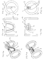
- Weitere Einzelheiten und Vorteile der vorliegenden Erfindung werden anhand der Figurenbeschreibung unter Bezugnahme auf die in den Zeichnungen dargestellten Ausführungsbeispiele im Folgenden näher erläutert. Darin zeigen:
- Fig. 1
- eine perspektivische Darstellung der Anordnung,
- Fig. 2
- eine Seitenansicht der Anordnung,
- Fig. 3
- einen Ofenaufsatz beim Einbringen der Anordnung,
- Fig. 3a
- ein Detail aus
Fig. 3 , - Fig. 4
- eine Frontansicht des Aufsatzes,
- Fig. 5
- einen Schnitt durch den Aufsatz,
- Fig. 5a
- ein Detail aus
Fig. 5 - Fig. 6a - 6c
- unterschiedliche Ansichten einer weiteren Aufhängvariante,
- Fig. 7a - 7c
- unterschiedliche Ansichten einer Aufhängvariante für ein relativ kleines Dentalwerkstück,
- Fig. 8a - 8d
- unterschiedliche Ansichten und ein Schnitt einer Aufhängvariante mit einer Klemmvorrichtung,
- Fig. 9a & 9b
- unterschiedliche Ansichten eines Dentalwerkstücks mit einem Steg und
- Fig. 10a & 10b
- unterschiedliche Ansichten des Stegs bei entferntem Basiselement.
- In den
Fig. 1 und 2 ist eine Anordnung 1 dargestellt, welche einerseits die Haltevorrichtung 3 und andererseits das bearbeitete Dentalwerkstück 2 aufweist. Die Haltevorrichtung 3 umfasst dabei zwei seitliche, scheibenförmige Steher 12, die über einen Träger 13 verbunden sind. Diese Haltevorrichtung 3 ist einstückig ausgebildet und besteht aus einem harten Aluminiumoxidschaum. Demgegenüber kann das Dentalwerkstück 2 z. B. aus Zirkon oder aus Dentalmetall bestehen. Dieses in einer Bearbeitungs- bzw. Fräsvorrichtung bearbeitete Dentalwerkstück 2 weist eine mindestens fünfgliedrige, vorzugsweise mindestens achtgliedrige, Dentalkonstruktion 4 auf. Die einzelnen Glieder 5 dieser zirkulären Dentalkonstruktion 4 sind jeweils über Verbindungsstege 7 mit einem plattenförmigen Basiselement 8 verbunden. In der Mittelachse M dieses Dentalwerkstücks 2 ist im Basiselement 8 das Verbindungsstück 6 in Form einer Ausnehmung ausgebildet. Über das bolzenförmig ausgebildete Aufhängelement 9 - welches das Verbindungsgegenstück 10 zum Verbindungsstück 6 bildet - ist das Dentalwerkstück 2 an der Haltevorrichtung 3 aufgehängt, wobei das Aufhängelement 9 in einer Ausnehmung 11 an der Haltevorrichtung 3 lösbar verbunden ist. Das Aufhängelement 9 verbindet somit das Dentalwerkstück 2 mit der Haltevorrichtung 3. In diesem Fall besteht somit die Anordnung 1 aus den drei Komponenten Dentalwerkstück 2, Haltevorrichtung 3 und Aufhängelement 9. - Im Gegensatz zum bevorzugten Ausführungsbeispiel gemäß den
Fig. 1 und 2 kann die Aufhängung auch andersartig ausgestaltet sein. So kann beispielsweise das Verbindungsstück 6 als Vorsprung ausgebildet sein und direkt in die Ausnehmung 11 - die dann das Verbindungsgegenstück 10 bildet - in der Haltevorrichtung 3 eingreifen. Auch ist es möglich, dass das Aufhängelement 9 einstückig mit der Haltevorrichtung 3 ausgebildet ist und somit von dieser vorsteht und an diesem Aufhängelement 9 dann das Dentalwerkstück 2 über das als Ausnehmung ausgebildete Verbindungsstück 6 aufgehängt ist. - Die
Fig. 3 zeigt einen Aufsatz 16, der eine Tür eines Sinterofens 14 bildet. An diesem Aufsatz 16 sind Türgriffe 21 montiert. InFig. 3a ist der vordere Teil dieses Aufsatzes 16 mit der Einführöffnung 19 erkennbar. Von dieser Einführöffnung 19 führt auch der Anschluss 18 weg, über den eine Verbindung mit der nur strichliert angedeuteten Vorrichtung 17 zum Erzeugen eines Vakuums oder zur Einleitung von Schutzgas verbunden ist. -
Fig. 4 zeigt eine Frontansicht des Aufsatzes 16, wobei auch hier wiederum der Anschluss 18 und die Türgriffe 21 erkennbar sind. -
Fig. 5 zeigt einen Schnitt durch den Aufsatz 16, wobei auch das im Aufsatz 16 lösbar gehaltene, rohrförmige Gehäuse 15 dargestellt ist. Dieses Gehäuse 15 bildet ein Vakuumsinterrohr. Das Gehäuse 15 ist durch den Verschlussdeckel 20 verschließbar, wodurch nach Einleitung eines Schutzgases bzw. nach Erzeugung eines Vakuums über den Anschluss 18 das im Gehäuse 15 angeordnete Dentalwerkstück 2 im Sinterofen 14 gesintert wird. Das Ofengehäuse 22 des Sinterofens 14 ist inFig. 5 nur durch Strichlierung angedeutet. Es ist aber gut ersichtlich, dass das an der Haltevorrichtung 3 aufgehängte Dentalwerkstück im Ofenraum R (Brennraum) dieses Sinterofens 14 angeordnet ist. InFig. 5a ist auch gut ersichtlich, dass die Außenkontur der Haltevorrichtung 3 bzw. insbesondere der scheibenförmigen Steher 12 an die Innenkontur des rohrförmigen Gehäuses 15 angepasst ist, wodurch ein sicherer Halt gegeben ist. - Durch das Aufhängen des mindestens fünfgliedrigen Dentalwerkstücks 2 an einer Haltevorrichtung 3 beim Sintern in einem Sinterofen 14 ist garantiert, dass es zu keinen ungewünschten Verzug kommt. Natürlich kann das Dentalwerkstück 2 auch direkt im Ofenraum R - also ohne Vakuumsinterrohr bzw. Gehäuse 15 - gesintert werden. Dann ist der Sinterofen 14 anstatt mit dem Aufsatz 16 mit einer normalen Türe verschlossen. Bei einem derartigen Einsatz kann die Haltevorrichtung 3 natürlich auch eine andere Form mit einer ebenen Stehfläche aufweisen.
- In den
Fig. 6a, 6b und 6c sind drei unterschiedliche Ansichten einer weiteren Ausführungsvariante einer Anordnung 1 dargestellt. In diesem Fall ist die Ausnehmung 11 in der Haltevorrichtung 3 als eine längliche Vertiefung an der Oberseite des Trägers 13 der Haltevorrichtung 3 ausgebildet. In dieser Vertiefung liegt das Aufhängelement 9 auf. Das Verbindungsstück 6 ist als Ausnehmung im obersten Bereich des plattenförmigen Basiselements 8 ausgebildet. Über diese Ausnehmung hält das Aufhängelement 9 das Dentalwerkstück 2 an der Haltevorrichtung 3. Die Steher 12 sind bei des Ausführung ringförmig und mit einem abgeflachten Stehbereich ausgebildet. - Die
Fig. 7a, 7b und 7c zeigen unterschiedliche Ansichten einer Anordnung 1 mit einer relativ kleinen, in diesem Falle fünfgliedrigen Dentalkonstruktion 4, welche über Verbindungsstege 7 mit einem horizontal ausgerichteten Basiselement 8 verbunden ist. - Das Aufhängelement 9 weist Haltevorsprünge 23 auf, auf welchen das Basiselement 8 aufliegt. Diese Aufliegeflächen des Basiselements 8 bilden in diesem Fall das Verbindungsstück 6. Gleich wie bei der vorherigen Variante ist auch hier wieder das Aufhängelement 9 in einer als längliche Vertiefung ausgebildeten Ausnehmung 11 an der Haltevorrichtung 3 aufgehängt. Es können auch mehrere solcher relativ kleiner Dentalwerkstücke 2 über ein Aufhängelement, welches mehrere nebeneinander angeordnete Haltevorsprünge 23 aufweist, oder über mehrere separate Aufhängelemente 9 an einer Haltevorrichtung 3 aufgehängt werden.
- In den
Fig. 8a, 8b, 8c und 8d sind drei unterschiedliche Ansichten und ein Schnitt durch noch eine weitere Ausführungsvariante einer Anordnung 1 abgebildet. Gemäß dieser Variante wird das Aufhängelement 9 durch eine Klemmvorrichtung gebildet. Diese Klemmvorrichtung weist zwei Klemmbacken 24 auf, welche von oben in eine mit schrägen Seitenflächen versehene Ausnehmung 11 im Träger 13 eingesetzt wird. Dabei kommen die ebenfalls abgeschrägten Keilflächen 25 der Klemmbacken 24 in Kontakt mit den schrägen Seitenflächen der Ausnehmung 11. Dadurch werden die Klemmbacken 24 zueinander bewegt, wodurch das zwischen den Klemmbacken 24 befindliche Basiselement 8 des Dentalwerkstücks 2 in der Klemmvorrichtung eingeklemmt und dadurch an der Haltevorrichtung 3 aufgehängt wird. Das Verbindungsstück 6 wird in diesem Fall durch die an den Innenseiten der Klemmbacken 24 anliegenden Oberflächenbereiche des Basiselements 8 gebildet. - Die
Fig. 9a und 9b zeigen unterschiedliche Ansichten eines Dentalwerkstücks 2, bei welchem die Dentalkonstruktion 4 nicht als im Wesentlichen vollständiger Zahnersatz (wie bei allen vorherigen schematischen Figuren) sondern als Steg ausgebildet ist. Dieser Steg kann zum Beispiel über eine Klippverbindung oder sonstige, dem Zahntechniker bekannte Methoden, zum Anbringen des eigentlichen Zahnersatzaufbaus verwendet werden. Auch ein solches Dentalwerkstück 2 kann wie beschrieben an einer Haltevorrichtung 3 aufgehängt werden. - Auf einen solchen Steg - welcher in den
Fig. 10 und 10b ohne Verbindungsstege 7 und Basiselement 8 dargestellt ist - wird dann in späterer Folge wie beschrieben ein entsprechender Zahnersatz aufgesetzt bzw. aufgebaut. -
- 1
- Anordnung
- 2
- Dentalwerkstück
- 3
- Haltevorrichtung
- 4
- Dentalkonstruktion
- 5
- Glieder
- 6
- Verbindungsstück
- 7
- Verbindungsstege
- 8
- Basiselement
- 9
- Aufhängelement
- 10
- Verbindungsgegenstück
- 11
- Ausnehmung in Haltevorrichtung
- 12
- Steher
- 13
- Träger
- 14
- Sinterofen
- 15
- Gehäuse
- 16
- Aufsatz
- 17
- Vorrichtung (für Vakuumerzeugung oder Schutzgaseinleitung)
- 18
- Anschluss
- 19
- Einführöffnung
- 20
- Verschlussdeckel
- 21
- Türgriffe
- 22
- Ofengehäuse
- 23
- Haltevorsprünge
- 24
- Klemmbacken
- 25
- abgeschrägte Keilflächen
- M
- Mittelachse
- R
- Ofenraum
Claims (16)
- Anordnung (1) zum Sintern eines Dentalwerkstücks (2), mit einem bearbeiteten Dentalwerkstück (2) und einer Haltevorrichtung (3) für das Dentalwerkstück (2), wobei- das Dentalwerkstück (2) größenmäßig einer Dentalkonstruktion (4) mit zumindest fünf, vorzugsweise mit zumindest acht, miteinander verbundenen Gliedern (5) entspricht,- das Dentalwerkstück (2) an der Haltevorrichtung (3) aufgehängt ist und- das Dentalwerkstück (2) über ein im oder am Dentalwerkstück (2) ausgebildetes, von der Dentalkonstruktion (4) gesondertes Verbindungsstück (6) mit der Haltevorrichtung (3) verbunden bzw. verbindbar ist.
- Anordnung nach Anspruch 1, wobei die Dentalkonstruktion (4) als zumindest bereichsweise, vorzugsweise vollständig, zirkulär geformte Brückenkonstruktion oder als zumindest bereichsweise, vorzugsweise vollständig, zirkulär geformter Steg ausgebildet ist.
- Anordnung nach Anspruch 1 oder 2, wobei das Dentalwerkstück (2) Verbindungsstege (7) und ein, vorzugsweise plattenförmiges, Basiselement (8) aufweist, wobei die Dentalkonstruktion (4) über die Verbindungsstege (7) mit dem Basiselement (8) verbunden ist.
- Anordnung nach Anspruch 3, wobei das Verbindungsstück (6) im oder am Basiselement (8) ausgebildet ist.
- Anordnung nach Anspruch 3 oder 4, wobei die Dentalkonstruktion (4), die Verbindungsstege (7) und das Basiselement (8) einstückig ausgebildet sind und das bearbeitete Dentalwerkstück (2) bilden.
- Anordnung nach einem der Ansprüche 3 bis 5, wobei das Verbindungsstück (6) als Ausnehmung oder als Vorsprung im Basiselement (8) ausgebildet ist.
- Anordnung nach einem der Ansprüche 1 bis 6, mit einem Aufhängelement (9), wobei das Dentalwerkstück (2) über das Aufhängelement (9), vorzugsweise über ein einziges Aufhängelement (9), an der Haltevorrichtung (3) aufgehängt ist.
- Anordnung nach Anspruch 7, wobei das Aufhängelement (9) durch das als Vorsprung ausgebildete Verbindungsstück (6) gebildet ist und mit einer in der Haltevorrichtung (3) ausgebildeten Ausnehmung, welche ein Verbindungsgegenstück (10) bildet, lösbar verbunden ist.
- Anordnung nach Anspruch 7, wobei das Aufhängelement (9) als vom Dentalwerkstück (2) separates Verbindungsgegenstück (10) ausgebildet ist, wobei das Aufhängelement (9) über das als Ausnehmung im Dentalwerkstück (2) ausgebildete Verbindungsstück (6) mit dem Dentalwerkstück (2) lösbar verbunden ist.
- Anordnung nach Anspruch 9, wobei das Aufhängelement (9) als an der Haltevorrichtung (3) ausgebildeter, mit der Haltevorrichtung (3) einstückiger Vorsprung ausgebildet ist.
- Anordnung nach Anspruch 9 , wobei das Aufhängelement (9) von der Haltevorrichtung (3) gesondert ausgebildet und an der Haltevorrichtung (3) bewegbar gelagert ist.
- Anordnung nach Anspruch 11, wobei das Aufhängelement (9) an einer in der Haltevorrichtung (3) ausgebildeten, vorzugsweise horizontal ausgerichteten, Ausnehmung (11) bewegbar gelagert ist.
- Anordnung nach Anspruch 11 oder 12, wobei das, vorzugsweise bolzenförmig ausgebildete, Aufhängelement (9) bei aufgehängtem Dentalwerkstück (2) sowohl durch die Ausnehmung (11) in der Haltevorrichtung (3) als auch durch die, das Verbindungstück (6) bildende Ausnehmung im Basiselement (8) des Dentalwerkstücks (2) hindurchragt.
- Anordnung nach Anspruch 7, wobei das Aufhängelement (9) als Klemmvorrichtung ausgebildet ist, welche in einer Klemmstellung über Klemmbacken (24) am Basiselement (8) anliegt.
- Verfahren zum Sintern eines Dentalwerkstücks (2), mit einem Dentalwerkstück (2), einer Haltevorrichtung (3) für das Dentalwerkstück (2) und einem Sinterofen (14), mit den Schritten:- Bearbeiten des Dentalwerkstücks (2), sodass das Dentalwerkstück (2) eine Dentalkonstruktion (4) mit zumindest fünf, vorzugsweise mit zumindest acht, miteinander verbundenen Gliedern (5) aufweist,- Aufhängen des Dentalwerkstück (2) an der Haltevorrichtung (3) durch Verbinden des Dentalwerkstücks (2) mit der Haltevorrichtung (3) über ein im oder am Dentalwerkstück (2) ausgebildetes, von der Dentalkonstruktion (4) gesondertes Verbindungsstück (6) und- Sintern, vorzugsweise sauerstofffreies Sintern, des an der Haltevorrichtung (3) aufgehängten Dentalwerkstücks (2).
- Verfahren nach Anspruch 15, wobei das Dentalwerkstück (2) Verbindungsstege (7) und eine Basiselement (8) aufweist und die Dentalkonstruktion (4) über die Verbindungsstege (7) mit dem Basiselement (8) verbunden ist, wobei das Verbindungsstück (6) im oder am Basiselement (8) ausgebildet ist.
Applications Claiming Priority (1)
| Application Number | Priority Date | Filing Date | Title |
|---|---|---|---|
| ATA569/2014A AT516076B1 (de) | 2014-07-18 | 2014-07-18 | Vorrichtung zum Sintern eines Dentalwerkstücks |
Publications (2)
| Publication Number | Publication Date |
|---|---|
| EP2974689A1 true EP2974689A1 (de) | 2016-01-20 |
| EP2974689B1 EP2974689B1 (de) | 2018-05-23 |
Family
ID=53793905
Family Applications (1)
| Application Number | Title | Priority Date | Filing Date |
|---|---|---|---|
| EP15002103.8A Active EP2974689B1 (de) | 2014-07-18 | 2015-07-15 | Anordnung zum sintern eines dentalwerkstücks |
Country Status (4)
| Country | Link |
|---|---|
| EP (1) | EP2974689B1 (de) |
| KR (1) | KR101737694B1 (de) |
| AT (1) | AT516076B1 (de) |
| ES (1) | ES2684622T3 (de) |
Cited By (2)
| Publication number | Priority date | Publication date | Assignee | Title |
|---|---|---|---|---|
| AT15966U1 (de) * | 2016-09-28 | 2018-10-15 | Steger Heinrich | Verfahren zum Sintern einer Dentalkonstruktion |
| IT201700082547A1 (it) * | 2017-07-20 | 2019-01-20 | Michael Oberhammer | Procedimento per la realizzazione di elementi per mezzo di sinterizzazione, in particolare protesi dentarie o parti di protesi dentarie e una struttura realizzata per mezzo di detto procedimento |
Families Citing this family (2)
| Publication number | Priority date | Publication date | Assignee | Title |
|---|---|---|---|---|
| KR102325270B1 (ko) * | 2021-04-08 | 2021-11-12 | 주식회사 디오 | 조립식 디지털보철 제조방법 |
| KR102325268B1 (ko) * | 2021-04-08 | 2021-11-11 | 주식회사 디오 | 조립식 디지털보철 |
Citations (5)
| Publication number | Priority date | Publication date | Assignee | Title |
|---|---|---|---|---|
| US4299567A (en) * | 1980-02-01 | 1981-11-10 | Asami Tanaka | Support structure |
| EP1154969B1 (de) | 1999-02-04 | 2003-05-14 | 3M Espe AG | Verfahren zum dimensionstreuen sintern von keramik |
| EP1712534A1 (de) * | 2005-04-13 | 2006-10-18 | 3M Innovative Properties Company | Vorrichtung und Verfahren zum dimensionsstabilen Sintern von vorgefomten keramischen Artikeln |
| EP2014254A1 (de) | 2007-06-07 | 2009-01-14 | Nobel Biocare Services AG | Verfahren und Anordnung zur Formung einer Zahnbrücke |
| DE102009044461A1 (de) | 2009-11-06 | 2011-05-26 | Degudent Gmbh | Verfahren zum dimensionstreuen Sintern eines Formteils |
Family Cites Families (1)
| Publication number | Priority date | Publication date | Assignee | Title |
|---|---|---|---|---|
| SE535361C2 (sv) * | 2010-11-10 | 2012-07-10 | Biomain Ab | Dentalbryggor och superstrukturer, samt metoder för att tillverka dessa |
-
2014
- 2014-07-18 AT ATA569/2014A patent/AT516076B1/de not_active IP Right Cessation
-
2015
- 2015-07-15 EP EP15002103.8A patent/EP2974689B1/de active Active
- 2015-07-15 ES ES15002103.8T patent/ES2684622T3/es active Active
- 2015-07-17 KR KR1020150102001A patent/KR101737694B1/ko active Active
Patent Citations (6)
| Publication number | Priority date | Publication date | Assignee | Title |
|---|---|---|---|---|
| US4299567A (en) * | 1980-02-01 | 1981-11-10 | Asami Tanaka | Support structure |
| EP1154969B1 (de) | 1999-02-04 | 2003-05-14 | 3M Espe AG | Verfahren zum dimensionstreuen sintern von keramik |
| EP1712534A1 (de) * | 2005-04-13 | 2006-10-18 | 3M Innovative Properties Company | Vorrichtung und Verfahren zum dimensionsstabilen Sintern von vorgefomten keramischen Artikeln |
| EP1868961B1 (de) | 2005-04-13 | 2009-10-14 | 3M Innovative Properties Company | Vorrichtung und verfahren zum dimensionsstabilen sintern von vorgefomten keramischen artikeln |
| EP2014254A1 (de) | 2007-06-07 | 2009-01-14 | Nobel Biocare Services AG | Verfahren und Anordnung zur Formung einer Zahnbrücke |
| DE102009044461A1 (de) | 2009-11-06 | 2011-05-26 | Degudent Gmbh | Verfahren zum dimensionstreuen Sintern eines Formteils |
Cited By (3)
| Publication number | Priority date | Publication date | Assignee | Title |
|---|---|---|---|---|
| AT15966U1 (de) * | 2016-09-28 | 2018-10-15 | Steger Heinrich | Verfahren zum Sintern einer Dentalkonstruktion |
| EP3300818B1 (de) * | 2016-09-28 | 2020-01-08 | STEGER, Heinrich | Verfahren zum sintern einer dentalkonstruktion und anordnung zum sintern einer dentalkonstruktion |
| IT201700082547A1 (it) * | 2017-07-20 | 2019-01-20 | Michael Oberhammer | Procedimento per la realizzazione di elementi per mezzo di sinterizzazione, in particolare protesi dentarie o parti di protesi dentarie e una struttura realizzata per mezzo di detto procedimento |
Also Published As
| Publication number | Publication date |
|---|---|
| EP2974689B1 (de) | 2018-05-23 |
| KR101737694B1 (ko) | 2017-05-18 |
| ES2684622T3 (es) | 2018-10-03 |
| AT516076A2 (de) | 2016-02-15 |
| AT516076B1 (de) | 2017-05-15 |
| AT516076A3 (de) | 2017-05-15 |
| KR20160010381A (ko) | 2016-01-27 |
Similar Documents
| Publication | Publication Date | Title |
|---|---|---|
| DE3201391C2 (de) | Geschiebeverbindung, sowie Verfahren und Vorrichtungzur Herstellung einer Geschiebeverbindung | |
| EP0064601B1 (de) | Verfahren zur Herstellung von Zahnersatzteilen | |
| EP2974689B1 (de) | Anordnung zum sintern eines dentalwerkstücks | |
| WO2015022296A1 (de) | Haltevorrichtung für einen abutmentrohling, system bestehend aus der halterung und dem abutmentrohling und verfahren zum haltern und bearbeiten des abutmentrohlings | |
| DE3534751C2 (de) | ||
| EP3191013B1 (de) | Sinterrohling | |
| DE102014106331A1 (de) | Werkstückträger | |
| CH714924A1 (de) | Kalibrierung verschiedener Geräte im digitalen Work-Flow eines Produktionsprozesses. | |
| EP3151781B1 (de) | Dentalrestaurationsmodell | |
| DE3930358C2 (de) | ||
| DE4210781C2 (de) | Serienmäßig hergestellte Kunstzahnrohlinge | |
| DE3535266C2 (de) | ||
| WO2014170111A1 (de) | Verfahren zur herstellung eines präzisionsgebissmodells für die herstellung/anpassung eines zahnersatzes | |
| DE4104299C2 (de) | Zahntechnischer Artikulator und Verfahren zur Herstellung von zahntechnischen Prothesen und Korrektureinrichtungen unter Verwendung des Artikulators | |
| DE4447161C1 (de) | Verfahren zur Herstellung von durchgehenden oder nichtdurchgehenden, profilierten Öffnungen in bedingt abnehmbaren sowie in herausnehmbaren Zahnersatzteilen aus Vollkeramik | |
| DE19624864C2 (de) | Restaurationsstift | |
| DE202006001796U1 (de) | Zahnimplantat | |
| EP0306864A1 (de) | Verfahren zur Herstellung von Zahnersatz und/oder Zahnersatzteilen | |
| DE339637C (de) | Verbindung fuer Zahnersatzteile | |
| EP0175054A1 (de) | Verfahren zur Herstellung von Zahnersatzteilen | |
| DE102006042919B3 (de) | Kiefer-Implantat-System, und Verfahren zum Herstellen eines Zahnersatzes | |
| DE102017221344A1 (de) | Zahnersatzformblock und Verfahren zur Herstellung eines Zahnersatzteils aus dem Zahnersatzformblock | |
| DE574470C (de) | Verfahren zur Herstellung zahnaerztlicher Kronen-, Bruecken- und Schienenarbeiten | |
| DE19909873A1 (de) | Verfahren zur Herstellung von herausnehmbaren, am Restzahnbestand zu befestigendem Zahnersatz | |
| DE4120132A1 (de) | Zahnersatz |
Legal Events
| Date | Code | Title | Description |
|---|---|---|---|
| PUAI | Public reference made under article 153(3) epc to a published international application that has entered the european phase |
Free format text: ORIGINAL CODE: 0009012 |
|
| AK | Designated contracting states |
Kind code of ref document: A1 Designated state(s): AL AT BE BG CH CY CZ DE DK EE ES FI FR GB GR HR HU IE IS IT LI LT LU LV MC MK MT NL NO PL PT RO RS SE SI SK SM TR |
|
| AX | Request for extension of the european patent |
Extension state: BA ME |
|
| 17P | Request for examination filed |
Effective date: 20160224 |
|
| RBV | Designated contracting states (corrected) |
Designated state(s): AL AT BE BG CH CY CZ DE DK EE ES FI FR GB GR HR HU IE IS IT LI LT LU LV MC MK MT NL NO PL PT RO RS SE SI SK SM TR |
|
| GRAP | Despatch of communication of intention to grant a patent |
Free format text: ORIGINAL CODE: EPIDOSNIGR1 |
|
| STAA | Information on the status of an ep patent application or granted ep patent |
Free format text: STATUS: GRANT OF PATENT IS INTENDED |
|
| INTG | Intention to grant announced |
Effective date: 20180207 |
|
| GRAS | Grant fee paid |
Free format text: ORIGINAL CODE: EPIDOSNIGR3 |
|
| GRAA | (expected) grant |
Free format text: ORIGINAL CODE: 0009210 |
|
| STAA | Information on the status of an ep patent application or granted ep patent |
Free format text: STATUS: THE PATENT HAS BEEN GRANTED |
|
| AK | Designated contracting states |
Kind code of ref document: B1 Designated state(s): AL AT BE BG CH CY CZ DE DK EE ES FI FR GB GR HR HU IE IS IT LI LT LU LV MC MK MT NL NO PL PT RO RS SE SI SK SM TR |
|
| REG | Reference to a national code |
Ref country code: GB Ref legal event code: FG4D Free format text: NOT ENGLISH |
|
| REG | Reference to a national code |
Ref country code: CH Ref legal event code: EP |
|
| REG | Reference to a national code |
Ref country code: IE Ref legal event code: FG4D Free format text: LANGUAGE OF EP DOCUMENT: GERMAN |
|
| REG | Reference to a national code |
Ref country code: AT Ref legal event code: REF Ref document number: 1000899 Country of ref document: AT Kind code of ref document: T Effective date: 20180615 |
|
| REG | Reference to a national code |
Ref country code: DE Ref legal event code: R096 Ref document number: 502015004336 Country of ref document: DE |
|
| REG | Reference to a national code |
Ref country code: FR Ref legal event code: PLFP Year of fee payment: 4 |
|
| REG | Reference to a national code |
Ref country code: NL Ref legal event code: MP Effective date: 20180523 |
|
| REG | Reference to a national code |
Ref country code: ES Ref legal event code: FG2A Ref document number: 2684622 Country of ref document: ES Kind code of ref document: T3 Effective date: 20181003 |
|
| REG | Reference to a national code |
Ref country code: LT Ref legal event code: MG4D |
|
| PG25 | Lapsed in a contracting state [announced via postgrant information from national office to epo] |
Ref country code: BG Free format text: LAPSE BECAUSE OF FAILURE TO SUBMIT A TRANSLATION OF THE DESCRIPTION OR TO PAY THE FEE WITHIN THE PRESCRIBED TIME-LIMIT Effective date: 20180823 Ref country code: FI Free format text: LAPSE BECAUSE OF FAILURE TO SUBMIT A TRANSLATION OF THE DESCRIPTION OR TO PAY THE FEE WITHIN THE PRESCRIBED TIME-LIMIT Effective date: 20180523 Ref country code: NO Free format text: LAPSE BECAUSE OF FAILURE TO SUBMIT A TRANSLATION OF THE DESCRIPTION OR TO PAY THE FEE WITHIN THE PRESCRIBED TIME-LIMIT Effective date: 20180823 Ref country code: SE Free format text: LAPSE BECAUSE OF FAILURE TO SUBMIT A TRANSLATION OF THE DESCRIPTION OR TO PAY THE FEE WITHIN THE PRESCRIBED TIME-LIMIT Effective date: 20180523 Ref country code: LT Free format text: LAPSE BECAUSE OF FAILURE TO SUBMIT A TRANSLATION OF THE DESCRIPTION OR TO PAY THE FEE WITHIN THE PRESCRIBED TIME-LIMIT Effective date: 20180523 |
|
| PG25 | Lapsed in a contracting state [announced via postgrant information from national office to epo] |
Ref country code: HR Free format text: LAPSE BECAUSE OF FAILURE TO SUBMIT A TRANSLATION OF THE DESCRIPTION OR TO PAY THE FEE WITHIN THE PRESCRIBED TIME-LIMIT Effective date: 20180523 Ref country code: NL Free format text: LAPSE BECAUSE OF FAILURE TO SUBMIT A TRANSLATION OF THE DESCRIPTION OR TO PAY THE FEE WITHIN THE PRESCRIBED TIME-LIMIT Effective date: 20180523 Ref country code: RS Free format text: LAPSE BECAUSE OF FAILURE TO SUBMIT A TRANSLATION OF THE DESCRIPTION OR TO PAY THE FEE WITHIN THE PRESCRIBED TIME-LIMIT Effective date: 20180523 Ref country code: LV Free format text: LAPSE BECAUSE OF FAILURE TO SUBMIT A TRANSLATION OF THE DESCRIPTION OR TO PAY THE FEE WITHIN THE PRESCRIBED TIME-LIMIT Effective date: 20180523 Ref country code: GR Free format text: LAPSE BECAUSE OF FAILURE TO SUBMIT A TRANSLATION OF THE DESCRIPTION OR TO PAY THE FEE WITHIN THE PRESCRIBED TIME-LIMIT Effective date: 20180824 |
|
| PG25 | Lapsed in a contracting state [announced via postgrant information from national office to epo] |
Ref country code: RO Free format text: LAPSE BECAUSE OF FAILURE TO SUBMIT A TRANSLATION OF THE DESCRIPTION OR TO PAY THE FEE WITHIN THE PRESCRIBED TIME-LIMIT Effective date: 20180523 Ref country code: SK Free format text: LAPSE BECAUSE OF FAILURE TO SUBMIT A TRANSLATION OF THE DESCRIPTION OR TO PAY THE FEE WITHIN THE PRESCRIBED TIME-LIMIT Effective date: 20180523 Ref country code: EE Free format text: LAPSE BECAUSE OF FAILURE TO SUBMIT A TRANSLATION OF THE DESCRIPTION OR TO PAY THE FEE WITHIN THE PRESCRIBED TIME-LIMIT Effective date: 20180523 Ref country code: DK Free format text: LAPSE BECAUSE OF FAILURE TO SUBMIT A TRANSLATION OF THE DESCRIPTION OR TO PAY THE FEE WITHIN THE PRESCRIBED TIME-LIMIT Effective date: 20180523 Ref country code: CZ Free format text: LAPSE BECAUSE OF FAILURE TO SUBMIT A TRANSLATION OF THE DESCRIPTION OR TO PAY THE FEE WITHIN THE PRESCRIBED TIME-LIMIT Effective date: 20180523 Ref country code: PL Free format text: LAPSE BECAUSE OF FAILURE TO SUBMIT A TRANSLATION OF THE DESCRIPTION OR TO PAY THE FEE WITHIN THE PRESCRIBED TIME-LIMIT Effective date: 20180523 |
|
| REG | Reference to a national code |
Ref country code: DE Ref legal event code: R097 Ref document number: 502015004336 Country of ref document: DE |
|
| PG25 | Lapsed in a contracting state [announced via postgrant information from national office to epo] |
Ref country code: SM Free format text: LAPSE BECAUSE OF FAILURE TO SUBMIT A TRANSLATION OF THE DESCRIPTION OR TO PAY THE FEE WITHIN THE PRESCRIBED TIME-LIMIT Effective date: 20180523 |
|
| REG | Reference to a national code |
Ref country code: CH Ref legal event code: PL |
|
| PG25 | Lapsed in a contracting state [announced via postgrant information from national office to epo] |
Ref country code: LU Free format text: LAPSE BECAUSE OF NON-PAYMENT OF DUE FEES Effective date: 20180715 Ref country code: MC Free format text: LAPSE BECAUSE OF FAILURE TO SUBMIT A TRANSLATION OF THE DESCRIPTION OR TO PAY THE FEE WITHIN THE PRESCRIBED TIME-LIMIT Effective date: 20180523 |
|
| PLBE | No opposition filed within time limit |
Free format text: ORIGINAL CODE: 0009261 |
|
| STAA | Information on the status of an ep patent application or granted ep patent |
Free format text: STATUS: NO OPPOSITION FILED WITHIN TIME LIMIT |
|
| REG | Reference to a national code |
Ref country code: BE Ref legal event code: MM Effective date: 20180731 |
|
| REG | Reference to a national code |
Ref country code: IE Ref legal event code: MM4A |
|
| PG25 | Lapsed in a contracting state [announced via postgrant information from national office to epo] |
Ref country code: CH Free format text: LAPSE BECAUSE OF NON-PAYMENT OF DUE FEES Effective date: 20180731 Ref country code: IE Free format text: LAPSE BECAUSE OF NON-PAYMENT OF DUE FEES Effective date: 20180715 Ref country code: LI Free format text: LAPSE BECAUSE OF NON-PAYMENT OF DUE FEES Effective date: 20180731 |
|
| 26N | No opposition filed |
Effective date: 20190226 |
|
| PG25 | Lapsed in a contracting state [announced via postgrant information from national office to epo] |
Ref country code: BE Free format text: LAPSE BECAUSE OF NON-PAYMENT OF DUE FEES Effective date: 20180731 Ref country code: SI Free format text: LAPSE BECAUSE OF FAILURE TO SUBMIT A TRANSLATION OF THE DESCRIPTION OR TO PAY THE FEE WITHIN THE PRESCRIBED TIME-LIMIT Effective date: 20180523 |
|
| PG25 | Lapsed in a contracting state [announced via postgrant information from national office to epo] |
Ref country code: AL Free format text: LAPSE BECAUSE OF FAILURE TO SUBMIT A TRANSLATION OF THE DESCRIPTION OR TO PAY THE FEE WITHIN THE PRESCRIBED TIME-LIMIT Effective date: 20180523 |
|
| PG25 | Lapsed in a contracting state [announced via postgrant information from national office to epo] |
Ref country code: MT Free format text: LAPSE BECAUSE OF FAILURE TO SUBMIT A TRANSLATION OF THE DESCRIPTION OR TO PAY THE FEE WITHIN THE PRESCRIBED TIME-LIMIT Effective date: 20180523 |
|
| GBPC | Gb: european patent ceased through non-payment of renewal fee |
Effective date: 20190715 |
|
| PG25 | Lapsed in a contracting state [announced via postgrant information from national office to epo] |
Ref country code: TR Free format text: LAPSE BECAUSE OF FAILURE TO SUBMIT A TRANSLATION OF THE DESCRIPTION OR TO PAY THE FEE WITHIN THE PRESCRIBED TIME-LIMIT Effective date: 20180523 |
|
| PG25 | Lapsed in a contracting state [announced via postgrant information from national office to epo] |
Ref country code: GB Free format text: LAPSE BECAUSE OF NON-PAYMENT OF DUE FEES Effective date: 20190715 |
|
| PG25 | Lapsed in a contracting state [announced via postgrant information from national office to epo] |
Ref country code: PT Free format text: LAPSE BECAUSE OF FAILURE TO SUBMIT A TRANSLATION OF THE DESCRIPTION OR TO PAY THE FEE WITHIN THE PRESCRIBED TIME-LIMIT Effective date: 20180523 |
|
| PG25 | Lapsed in a contracting state [announced via postgrant information from national office to epo] |
Ref country code: HU Free format text: LAPSE BECAUSE OF FAILURE TO SUBMIT A TRANSLATION OF THE DESCRIPTION OR TO PAY THE FEE WITHIN THE PRESCRIBED TIME-LIMIT; INVALID AB INITIO Effective date: 20150715 Ref country code: CY Free format text: LAPSE BECAUSE OF FAILURE TO SUBMIT A TRANSLATION OF THE DESCRIPTION OR TO PAY THE FEE WITHIN THE PRESCRIBED TIME-LIMIT Effective date: 20180523 Ref country code: MK Free format text: LAPSE BECAUSE OF NON-PAYMENT OF DUE FEES Effective date: 20180523 |
|
| PG25 | Lapsed in a contracting state [announced via postgrant information from national office to epo] |
Ref country code: IS Free format text: LAPSE BECAUSE OF FAILURE TO SUBMIT A TRANSLATION OF THE DESCRIPTION OR TO PAY THE FEE WITHIN THE PRESCRIBED TIME-LIMIT Effective date: 20180923 |
|
| PGFP | Annual fee paid to national office [announced via postgrant information from national office to epo] |
Ref country code: FR Payment date: 20250623 Year of fee payment: 11 |
|
| PGFP | Annual fee paid to national office [announced via postgrant information from national office to epo] |
Ref country code: ES Payment date: 20250807 Year of fee payment: 11 |
|
| PGFP | Annual fee paid to national office [announced via postgrant information from national office to epo] |
Ref country code: DE Payment date: 20250731 Year of fee payment: 11 |
|
| PGFP | Annual fee paid to national office [announced via postgrant information from national office to epo] |
Ref country code: IT Payment date: 20250728 Year of fee payment: 11 |
|
| PGFP | Annual fee paid to national office [announced via postgrant information from national office to epo] |
Ref country code: AT Payment date: 20250729 Year of fee payment: 11 |