EP2974473B1 - Using motion to improve local wireless network connectivity - Google Patents
Using motion to improve local wireless network connectivity Download PDFInfo
- Publication number
- EP2974473B1 EP2974473B1 EP14726021.0A EP14726021A EP2974473B1 EP 2974473 B1 EP2974473 B1 EP 2974473B1 EP 14726021 A EP14726021 A EP 14726021A EP 2974473 B1 EP2974473 B1 EP 2974473B1
- Authority
- EP
- European Patent Office
- Prior art keywords
- motion state
- motion
- change event
- stationary
- local wireless
- Prior art date
- Legal status (The legal status is an assumption and is not a legal conclusion. Google has not performed a legal analysis and makes no representation as to the accuracy of the status listed.)
- Not-in-force
Links
Images


Classifications
-
- H—ELECTRICITY
- H04—ELECTRIC COMMUNICATION TECHNIQUE
- H04W—WIRELESS COMMUNICATION NETWORKS
- H04W48/00—Access restriction; Network selection; Access point selection
- H04W48/16—Discovering, processing access restriction or access information
-
- H—ELECTRICITY
- H04—ELECTRIC COMMUNICATION TECHNIQUE
- H04W—WIRELESS COMMUNICATION NETWORKS
- H04W52/00—Power management, e.g. TPC [Transmission Power Control], power saving or power classes
- H04W52/02—Power saving arrangements
- H04W52/0209—Power saving arrangements in terminal devices
- H04W52/0251—Power saving arrangements in terminal devices using monitoring of local events, e.g. events related to user activity
- H04W52/0254—Power saving arrangements in terminal devices using monitoring of local events, e.g. events related to user activity detecting a user operation or a tactile contact or a motion of the device
-
- H—ELECTRICITY
- H04—ELECTRIC COMMUNICATION TECHNIQUE
- H04W—WIRELESS COMMUNICATION NETWORKS
- H04W48/00—Access restriction; Network selection; Access point selection
- H04W48/02—Access restriction performed under specific conditions
- H04W48/04—Access restriction performed under specific conditions based on user or terminal location or mobility data, e.g. moving direction, speed
-
- H—ELECTRICITY
- H04—ELECTRIC COMMUNICATION TECHNIQUE
- H04W—WIRELESS COMMUNICATION NETWORKS
- H04W84/00—Network topologies
- H04W84/02—Hierarchically pre-organised networks, e.g. paging networks, cellular networks, WLAN [Wireless Local Area Network] or WLL [Wireless Local Loop]
- H04W84/10—Small scale networks; Flat hierarchical networks
- H04W84/12—WLAN [Wireless Local Area Networks]
-
- Y—GENERAL TAGGING OF NEW TECHNOLOGICAL DEVELOPMENTS; GENERAL TAGGING OF CROSS-SECTIONAL TECHNOLOGIES SPANNING OVER SEVERAL SECTIONS OF THE IPC; TECHNICAL SUBJECTS COVERED BY FORMER USPC CROSS-REFERENCE ART COLLECTIONS [XRACs] AND DIGESTS
- Y02—TECHNOLOGIES OR APPLICATIONS FOR MITIGATION OR ADAPTATION AGAINST CLIMATE CHANGE
- Y02D—CLIMATE CHANGE MITIGATION TECHNOLOGIES IN INFORMATION AND COMMUNICATION TECHNOLOGIES [ICT], I.E. INFORMATION AND COMMUNICATION TECHNOLOGIES AIMING AT THE REDUCTION OF THEIR OWN ENERGY USE
- Y02D30/00—Reducing energy consumption in communication networks
- Y02D30/70—Reducing energy consumption in communication networks in wireless communication networks
Definitions
- the disclosure is directed to using motion to improve local wireless network connectivity.
- Mobile devices such as cell phones, smart phones, tablet computers, laptops, personal digital assistants (PDAs), etc.
- PDAs personal digital assistants
- WLANs wireless local area networks
- WiFi networks WiFi networks
- Bluetooth networks etc.
- WLANs wireless local area networks
- Such networks are often used to provide data connectivity for mobile devices.
- maintaining a connection while a mobile device is moving from one geographic area to another can be challenging.
- a method for using motion to reduce unnecessary scans for local wireless networks includes determining whether or not a motion state change event of a user device indicates a change from a moving motion state to a stationary motion state, and if the motion state change event indicates a change from a moving motion state to a stationary motion state, ignoring the motion state change event.
- a method of using motion to reduce latency of scanning for local wireless networks includes determining whether or not a user device is in motion, determining whether or not a periodic scan timer has expired and/or a received signal strength indicator (RSSI) is below a threshold, and if the user device is in motion and the periodic scan timer has expired or the RSSI is below the threshold, scanning for a local wireless network.
- RSSI received signal strength indicator
- An apparatus for using motion to reduce unnecessary scans for local wireless networks includes logic configured to determine whether or not a motion state change event of a user device indicates a change from a moving motion state to a stationary motion state, and logic configured to ignore the motion state change event if the motion state change event indicates a change from a moving motion state to a stationary motion state.
- An apparatus for using motion to reduce latency of scanning for local wireless networks includes logic configured to determine whether or not a user device is in motion, logic configured to determine whether or not a periodic scan timer has expired and/or a received signal strength indicator (RSSI) is below a threshold, and logic configured to scan for a local wireless network if the user device is in motion and the periodic scan timer has expired or the RSSI is below the threshold.
- RSSI received signal strength indicator
- An apparatus for using motion to reduce unnecessary scans for local wireless networks includes means for determining whether or not a motion state change event of a user device indicates a change from a moving motion state to a stationary motion state, and means for ignoring the motion state change event if the motion state change event indicates a change from a moving motion state to a stationary motion state.
- An apparatus for using motion to reduce latency of scanning for local wireless networks includes means for determining whether or not a user device is in motion, means for determining whether or not a periodic scan timer has expired and/or a received signal strength indicator (RSSI) is below a threshold, and means for scanning for a local wireless network if the user device is in motion and the periodic scan timer has expired or the RSSI is below the threshold.
- RSSI received signal strength indicator
- a non-transitory computer-readable medium for using motion to reduce unnecessary scans for local wireless networks includes at least one instruction to determine whether or not a motion state change event of a user device indicates a change from a moving motion state to a stationary motion state, and at least one instruction to ignore the motion state change event if the motion state change event indicates a change from a moving motion state to a stationary motion state.
- a non-transitory computer-readable medium for using motion to reduce latency of scanning for local wireless networks includes at least one instruction to determine whether or not a user device is in motion, at least one instruction to determine whether or not a periodic scan timer has expired and/or a received signal strength indicator (RSSI) is below a threshold, and at least one instruction to scan for a local wireless network if the user device is in motion and the periodic scan timer has expired or the RSSI is below the threshold.
- RSSI received signal strength indicator
- a client device referred to herein as a user equipment (UE) may be mobile or stationary, and may communicate with a radio access network (RAN).
- UE may be referred to interchangeably as an "access terminal” or “AT,” a “wireless device,” a “subscriber device,” a “subscriber terminal,” a “subscriber station,” a “user terminal” or UT, a “mobile terminal,” a “mobile station” and variations thereof.
- AT access terminal
- AT wireless device
- subscriber device a “subscriber terminal”
- subscriber station a “user terminal” or UT
- UEs can communicate with a core network via the RAN, and through the core network the UEs can be connected with external networks such as the Internet.
- UEs can be embodied by any of a number of types of devices including but not limited to PC cards, compact flash devices, external or internal modems, wireless or wireline phones, and so on.
- a communication link through which UEs can send signals to the RAN is called an uplink channel (e.g., a reverse traffic channel, a reverse control channel, an access channel, etc.).
- a communication link through which the RAN can send signals to UEs is called a downlink or forward link channel (e.g., a paging channel, a control channel, a broadcast channel, a forward traffic channel, etc.).
- a downlink or forward link channel e.g., a paging channel, a control channel, a broadcast channel, a forward traffic channel, etc.
- traffic channel can refer to either an uplink / reverse or downlink / forward traffic channel.
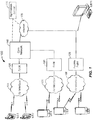
- FIG. 1 illustrates a high-level system architecture of a wireless communications system 100 in accordance with an aspect of the disclosure.
- the wireless communications system 100 contains UEs 1...N.
- the UEs 1...N can include cellular telephones, personal digital assistant (PDAs), pagers, a laptop computer, a desktop computer, and so on.
- PDAs personal digital assistant
- UEs 1...2 are illustrated as cellular calling phones
- UEs 3...5 are illustrated as cellular touchscreen phones or smart phones
- UE N is illustrated as a desktop computer or PC.
- UEs 1...N are configured to communicate with an access network (e.g., the RAN 120, an access point 125, etc.) over a physical communications interface or layer, shown in FIG. 1 as air interfaces 104, 106, 108 and/or a direct wired connection.
- an access network e.g., the RAN 120, an access point 125, etc.
- a physical communications interface or layer shown in FIG. 1 as air interfaces 104, 106, 108 and/or a direct wired connection.
- the air interfaces 104 and 106 can comply with a given cellular communications protocol (e.g., Code Division Multiple Access (CDMA), Evolution-Data Optimized (EV-DO), Evolved High Rate Packet Data (eHRPD), Global System of Mobile Communication (GSM), Enhanced Data rates for GSM Evolution (EDGE), Wideband CDMA (W-CDMA), Long-Term Evolution (LTE), etc.), while the air interface 108 can comply with a wireless IP protocol (e.g., IEEE 802.11).
- the RAN 120 includes a plurality of access points that serve UEs over air interfaces, such as the air interfaces 104 and 106.
- the access points in the RAN 120 can be referred to as access nodes or ANs, access points or APs, base stations or BSs, Node Bs, eNode Bs, and so on. These access points can be terrestrial access points (or ground stations), or satellite access points.
- the RAN 120 is configured to connect to a core network 140 that can perform a variety of functions, including bridging circuit switched (CS) calls between UEs served by the RAN 120 and other UEs served by the RAN 120 or a different RAN altogether, and can also mediate an exchange of packet-switched (PS) data with external networks such as Internet 175.
- the Internet 175 includes a number of routing agents and processing agents (not shown in FIG. 1 for the sake of convenience). In FIG.
- UE N is shown as connecting to the Internet 175 directly (i.e., separate from the core network 140, such as over an Ethernet connection of WiFi or 802.11-based network).
- the Internet 175 can thereby function to bridge packet-switched data communications between UE N and UEs 1...N via the core network 140.
- the access point 125 is also shown in FIG.1 .
- the access point 125 may be connected to the Internet 175 independent of the core network 140 (e.g., via an optical communication system such as FiOS, a cable modem, etc.).
- the air interface 108 may serve UE 4 or UE 5 over a local wireless connection, such as IEEE 802.11 in an example.
- UE N is shown as a desktop computer with a wired connection to the Internet 175, such as a direct connection to a modem or router, which can correspond to the access point 125 itself in an example (e.g., for a WiFi router with both wired and wireless connectivity).
- a modem or router which can correspond to the access point 125 itself in an example (e.g., for a WiFi router with both wired and wireless connectivity).
- an application server 170 is shown as connected to the Internet 175, the core network 140, or both.
- the application server 170 can be implemented as a plurality of structurally separate servers, or alternately may correspond to a single server.
- the application server 170 is configured to support one or more communication services (e.g., Voice-over-Internet Protocol (VoIP) sessions, Push-to-Talk (PTT) sessions, group communication sessions, social networking services, etc.) for UEs that can connect to the application server 170 via the core network 140 and/or the Internet 175.
- VoIP Voice-over-Internet Protocol
- PTT Push-to-Talk
- FIG. 2 illustrates examples of UEs in accordance with aspects of the disclosure.
- UE 200A is illustrated as a calling telephone and UE 200B is illustrated as a touchscreen device (e.g., a smart phone, a tablet computer, etc.).
- an external casing of UE 200A is configured with an antenna 205A, display 210A, at least one button 215A (e.g., a PTT button, a power button, a volume control button, etc.) and a keypad 220A among other components, as is known in the art.
- button 215A e.g., a PTT button, a power button, a volume control button, etc.
- an external casing of UE 200B is configured with a touchscreen display 205B, peripheral buttons 210B, 215B, 220B and 225B (e.g., a power control button, a volume or vibrate control button, an airplane mode toggle button, etc.), at least one front-panel button 230B (e.g., a Home button, etc.), among other components, as is known in the art.
- peripheral buttons 210B, 215B, 220B and 225B e.g., a power control button, a volume or vibrate control button, an airplane mode toggle button, etc.
- at least one front-panel button 230B e.g., a Home button, etc.
- the UE 200B can include one or more external antennas and/or one or more integrated antennas that are built into the external casing of UE 200B, including but not limited to WiFi antennas, cellular antennas, satellite position system (SPS) antennas (e.g., global positioning system (GPS) antennas), and so on.
- WiFi antennas e.g., WiFi
- cellular antennas e.g., cellular antennas
- satellite position system (SPS) antennas e.g., global positioning system (GPS) antennas
- GPS global positioning system
- the platform 202 can receive and execute software applications, data and/or commands transmitted from the RAN 120 that may ultimately come from the core network 140, the Internet 175 and/or other remote servers and networks (e.g., application server 170, web URLs, etc.).
- the platform 202 can also independently execute locally stored applications without RAN interaction.
- the platform 202 can include a transceiver 206 operably coupled to an application specific integrated circuit (ASIC) 208, or other processor, microprocessor, logic circuit, or other data processing device.
- ASIC application specific integrated circuit
- the ASIC 208 or other processor executes the application programming interface (API) 210 layer that interfaces with any resident programs in the memory 212 of the wireless device.
- the memory 212 can be comprised of read-only memory (ROM) or random-access memory (RAM), electrically erasable programmable ROM (EEPROM), flash cards, or any memory common to computer platforms.
- the platform 202 also can include a local database 214 that can store applications not actively used in memory 212, as well as other data.
- the local database 214 is typically a flash memory cell, but can be any secondary storage device as known in the art, such as magnetic media, EEPROM, optical media, tape, soft or hard disk, or the like.
- an aspect of the disclosure can include a UE (e.g., UE 200A, 200B, etc.) including the ability to perform the functions described herein.
- a UE e.g., UE 200A, 200B, etc.
- the various logic elements can be embodied in discrete elements, software modules executed on a processor or any combination of software and hardware to achieve the functionality disclosed herein.
- ASIC 208, memory 212, API 210 and local database 214 may all be used cooperatively to load, store and execute the various functions disclosed herein and thus the logic to perform these functions may be distributed over various elements.
- the functionality could be incorporated into one discrete component. Therefore, the features of the UEs 200A and 200B in FIG. 2 are to be considered merely illustrative and the disclosure is not limited to the illustrated features or arrangement.
- the wireless communication between the UEs 200A and/or 200B and the RAN 120 can be based on different technologies, such as CDMA, W-CDMA, time division multiple access (TDMA), frequency division multiple access (FDMA), Orthogonal Frequency Division Multiplexing (OFDM), GSM, or other protocols that may be used in a wireless communications network or a data communications network.
- CDMA Code Division Multiple Access
- W-CDMA time division multiple access
- FDMA frequency division multiple access
- OFDM Orthogonal Frequency Division Multiplexing
- GSM Global System for Mobile communications
- voice transmission and/or data can be transmitted to the UEs from the RAN using a variety of networks and configurations. Accordingly, the illustrations provided herein are not intended to limit the aspects of the disclosure and are merely to aid in the description of various aspects of the disclosure.
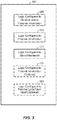
- FIG. 3 illustrates a communication device 300 that includes logic configured to perform functionality.
- the communication device 300 can correspond to any of the above-noted communication devices, including but not limited to UEs 200A or 200B, any component of the RAN 120, any component of the core network 140, any components coupled with the core network 140 and/or the Internet 175 (e.g., the application server 170), and so on.
- communication device 300 can correspond to any electronic device that is configured to communicate with (or facilitate communication with) one or more other entities over the wireless communications system 100 of FIG. 1 .
- the communication device 300 includes logic configured to receive and/or transmit information 305.
- the logic configured to receive and/or transmit information 305 can include a wireless communications interface (e.g., Bluetooth, WiFi, 2G, CDMA, W-CDMA, 3G, 4G, LTE, etc.) such as a wireless transceiver and associated hardware (e.g., an RF antenna, a MODEM, a modulator and/or demodulator, etc.).
- a wireless communications interface e.g., Bluetooth, WiFi, 2G, CDMA, W-CDMA, 3G, 4G, LTE, etc.
- a wireless transceiver and associated hardware e.g., an RF antenna, a MODEM, a modulator and/or demodulator, etc.
- the logic configured to receive and/or transmit information 305 can correspond to a wired communications interface (e.g., a serial connection, a USB or Firewire connection, an Ethernet connection through which the Internet 175 can be accessed, etc.).
- a wired communications interface e.g., a serial connection, a USB or Firewire connection, an Ethernet connection through which the Internet 175 can be accessed, etc.
- the logic configured to receive and/or transmit information 305 can correspond to an Ethernet card, in an example, that connects the network-based server to other communication entities via an Ethernet protocol.
- the logic configured to receive and/or transmit information 305 can include sensory or measurement hardware by which the communication device 300 can monitor its local environment (e.g., an accelerometer, a temperature sensor, a light sensor, an antenna for monitoring local RF signals, etc.).
- the logic configured to receive and/or transmit information 305 can also include software that, when executed, permits the associated hardware of the logic configured to receive and/or transmit information 305 to perform its reception and/or transmission function(s).
- the logic configured to receive and/or transmit information 305 does not correspond to software alone, and the logic configured to receive and/or transmit information 305 relies at least in part upon hardware to achieve its functionality.
- the communication device 300 further includes logic configured to process information 310.
- the logic configured to process information 310 can include at least a processor.
- Example implementations of the type of processing that can be performed by the logic configured to process information 310 includes but is not limited to performing determinations, establishing connections, making selections between different information options, performing evaluations related to data, interacting with sensors coupled to the communication device 300 to perform measurement operations, converting information from one format to another (e.g., between different protocols such as .wmv to .avi, etc.), and so on.
- the processor included in the logic configured to process information 310 can correspond to a general purpose processor, a digital signal processor (DSP), an ASIC, a field programmable gate array (FPGA) or other programmable logic device, discrete gate or transistor logic, discrete hardware components, or any combination thereof designed to perform the functions described herein.
- a general purpose processor may be a microprocessor, but in the alternative, the processor may be any conventional processor, controller, microcontroller, or state machine.
- a processor may also be implemented as a combination of computing devices, e.g., a combination of a DSP and a microprocessor, a plurality of microprocessors, one or more microprocessors in conjunction with a DSP core, or any other such configuration.
- the logic configured to process information 310 can also include software that, when executed, permits the associated hardware of the logic configured to process information 310 to perform its processing function(s). However, the logic configured to process information 310 does not correspond to software alone, and the logic configured to process information 310 relies at least in part upon hardware to achieve its functionality.
- the communication device 300 further includes logic configured to store information 315.
- the logic configured to store information 315 can include at least a non-transitory memory and associated hardware (e.g., a memory controller, etc.).
- the non-transitory memory included in the logic configured to store information 315 can correspond to RAM, flash memory, ROM, erasable programmable ROM (EPROM), EEPROM, registers, hard disk, a removable disk, a CD-ROM, or any other form of storage medium known in the art.
- the logic configured to store information 315 can also include software that, when executed, permits the associated hardware of the logic configured to store information 315 to perform its storage function(s). However, the logic configured to store information 315 does not correspond to software alone, and the logic configured to store information 315 relies at least in part upon hardware to achieve its functionality.
- the communication device 300 further optionally includes logic configured to present information 320.
- the logic configured to present information 320 can include at least an output device and associated hardware.
- the output device can include a video output device (e.g., a display screen, a port that can carry video information such as USB, HDMI, etc.), an audio output device (e.g., speakers, a port that can carry audio information such as a microphone jack, USB, HDMI, etc.), a vibration device and/or any other device by which information can be formatted for output or actually outputted by a user or operator of the communication device 300.
- a video output device e.g., a display screen, a port that can carry video information such as USB, HDMI, etc.
- an audio output device e.g., speakers, a port that can carry audio information such as a microphone jack, USB, HDMI, etc.
- a vibration device e.g., a vibration device by which information can be formatted for output or actually outputted by a user or operator of the
- the logic configured to present information 320 can include the display 210A of UE 200A or the touchscreen display 205B of UE 200B. In a further example, the logic configured to present information 320 can be omitted for certain communication devices, such as network communication devices that do not have a local user (e.g., network switches or routers, remote servers, etc.).
- the logic configured to present information 320 can also include software that, when executed, permits the associated hardware of the logic configured to present information 320 to perform its presentation function(s). However, the logic configured to present information 320 does not correspond to software alone, and the logic configured to present information 320 relies at least in part upon hardware to achieve its functionality.
- the communication device 300 further optionally includes logic configured to receive local user input 325.
- the logic configured to receive local user input 325 can include at least a user input device and associated hardware.
- the user input device can include buttons, a touchscreen display, a keyboard, a camera, an audio input device (e.g., a microphone or a port that can carry audio information such as a microphone jack, etc.), and/or any other device by which information can be received from a user or operator of the communication device 300.
- the communication device 300 corresponds to UE 200A or UE 200B as shown in FIG.
- the logic configured to receive local user input 325 can include the keypad 220A, any of the buttons 215A or 210B through 225B, the touchscreen display 205B, etc.
- the logic configured to receive local user input 325 can be omitted for certain communication devices, such as network communication devices that do not have a local user (e.g., network switches or routers, remote servers, etc.).
- the logic configured to receive local user input 325 can also include software that, when executed, permits the associated hardware of the logic configured to receive local user input 325 to perform its input reception function(s). However, the logic configured to receive local user input 325 does not correspond to software alone, and the logic configured to receive local user input 325 relies at least in part upon hardware to achieve its functionality.
- any software used to facilitate the functionality of the configured logics of 305 through 325 can be stored in the non-transitory memory associated with the logic configured to store information 315, such that the configured logics of 305 through 325 each performs their functionality (i.e., in this case, software execution) based in part upon the operation of software stored by the logic configured to store information 315.
- hardware that is directly associated with one of the configured logics can be borrowed or used by other configured logics from time to time.
- the processor of the logic configured to process information 310 can format data into an appropriate format before being transmitted by the logic configured to receive and/or transmit information 305, such that the logic configured to receive and/or transmit information 305 performs its functionality (i.e., in this case, transmission of data) based in part upon the operation of hardware (i.e., the processor) associated with the logic configured to process information 310.
- logic configured to as used throughout this disclosure is intended to invoke an aspect that is at least partially implemented with hardware, and is not intended to map to software-only implementations that are independent of hardware.
- the configured logic or “logic configured to” in the various blocks are not limited to specific logic gates or elements, but generally refer to the ability to perform the functionality described herein (either via hardware or a combination of hardware and software).
- the configured logics or “logic configured to” as illustrated in the various blocks are not necessarily implemented as logic gates or logic elements despite sharing the word “logic.” Other interactions or cooperation between the logic in the various blocks will become clear to one of ordinary skill in the art from a review of the aspects described below in more detail.
- Mobile UEs such as cell phones, smart phones, tablet computers, laptops, PDAs, etc.
- local wireless networks such as WLANs, WiFi networks, Bluetooth networks, etc.
- WLANs Wireless Fidelity
- WiFi networks Wireless Fidelity networks
- Bluetooth networks Wireless Fidelity networks
- Such networks are often used to provide data connectivity for mobile devices.
- maintaining a connection while a UE is moving from one geographic area to another can be challenging.
- UEs simply perform periodic scans when not-connected, and suppress all scans when connected. When connected, scans are suppressed to save energy, but this can hinder the ability of the UE to efficiently find and switch to a better access point (e.g. one with a higher signal-to-noise ratio (SNR)).
- SNR signal-to-noise ratio
- the rate of scanning is a tradeoff between power consumption and the delay of establishing a connection. This is especially an issue with moving UEs, where the best access point may be changing relatively quickly. For example, a UE may scan for local wireless networks while the user is driving, even though the UE will not be able to connect to a wireless network before the UE is out of range of that network. In another example, the UE may be stationary and not connected, in which case scanning for available wireless networks is unnecessary, at least after an initial scan.
- FIG. 4 illustrates exemplary tradeoffs between power and latency.
- Graph 410 illustrates the power consumption (in mA) for scan intervals of 5, 15 30, 60, and 120 seconds.
- Graph 420 illustrates the latency to connect to an access point (in seconds) for scan intervals of 5, 15 30, 60, and 120 seconds.
- the shorter the scan interval the higher the power consumption.
- the shorter the scan interval the shorter the connection latency.
- the motion state of the UE can be used to improve the power performance of the connectivity management. For instance, the motion state of the UE can be used to avoid unnecessary scans for available local wireless networks.
- the motion state classifier requires very little power, and thus is always on.
- scans are suppressed or slowed. The reason is that if the UE is not moving, then the access point signal strengths are unlikely to change significantly. Further, if a distance bound can be computed from the motion information, scans may be triggered only if the distance travelled exceeds a set threshold. This threshold can be set to optimize performance, and can be related to the coverage distance of the wireless network signals.
- the UE is connected and stationary, then scans are not likely to be needed (for connectivity purposes), and are suppressed or slowed. However, if motion is detected, then occasional scans may help the UE maintain connection with the best available access point. Further, a combination of signal strength and motion information can be used to determine the need for a scan. If the SNR for the connected access point is high, scans can be suppressed regardless of motion. However, if the SNR is low, scans can be triggered by motion, or by a distance travelled exceeding a set bound.
- Certain UE states do not fall into the above three categories and should be addressed separately. For example, if the UE is stationary and a new, closer access point is turned on, the UE will not detect the new access point if it is not performing scans. This rarely happens, and can be addressed by the UE performing a long-interval heartbeat scan (e.g. 300 seconds) when it is stationary. Another example is that the UE may be connected to a mobile hotspot while "in transit.” This can be addressed by treating mobile hotspots as a separate case. It can also be addressed by performing a long-interval heartbeat scan (e.g. 300 seconds).
- a long-interval heartbeat scan e.g. 300 seconds
- the motion of the UE can be classified into eight motion states: walk, run, sit, stand, absolute rest, fiddle, in-transit, and null.
- “Fiddle” means the user is holding the UE.
- “In-transit” means the mobile device is travelling in any vehicle, such as an automobile, a train, a plane, etc.
- "Null” means that the motion classifier cannot reach a level of confidence in the motion classification necessary to report a motion state.
- These eight fine-grained motion states can be remapped to two coarse-grained motion states: stationary (sit, stand, fiddle, absolute rest) and non-stationary (walk, run, in-transit). These coarse-grained motion states cause two motion state change events - the UE can go from stationary to non-stationary, or from non-stationary to stationary.
- the instant change detection (ICD) algorithm monitors consecutive motion states and detects any transition between stationary and non-stationary motion states (the algorithm ignores the null output).
- the cumulative sum control chart (CUSUM)-based change detection (CCD) algorithm accumulates and detects change upon crossing a maximum divided by two (e.g. the maximum may be 10 seconds).
- the CUSUM-based and collapse change detection (CCCD) algorithm detects change events within two minutes. This works because many of the CUSUM-based change events are generated within two minutes. The algorithm collapses, or combines, change events if they are generated within two minutes.
- Motion change events can be determined from a function that uses the parameters "event type,” "timestamp,” and "metadata.”
- the "event type” parameter can be a one-bit binary value that indicates whether or not the motion change event is a change from a "stationary" motion state to a "non-stationary” motion state. That is, a 1 can indicate a change from "stationary” to "non-stationary” and a 0 can indicate either no change or a change from "non-stationary” to "stationary.”
- the timestamp parameter can be a four byte value that indicates the epoch time.
- the metadata parameter is optional, and can indicate the current motion state and/or a confidence level in the motion state change.
- the metadata parameter can include a three-bit field to indicate the motion state (three bits provides eight unique states) and four bytes for the confidence level. There is no need to consider the packet header size.
- FIG. 5 illustrates an exemplary architecture of a UE according to at least one aspect.
- the architecture illustrated in FIG. 5 includes a motion state manager 530 coupled to one or more sensors 510, a disconnected state manager 540, and a connected state manager 560.
- the disconnected state manager 540 and the connected state manager 560 are coupled to a local wireless network detector 520 for detecting local wireless networks.
- the local wireless network detector 520 may be an RF antenna and associated firmware.
- a motion detector 532 receives input from the sensor(s) 510.
- the motion detector 532 passes motion data to the motion state classifier 534, which classifies the motion as one of sitting, standing, fiddling, absolute rest, walking, running, or in-transit.
- the motion state classifier 534 passes the motion state to the motion state change detector 536, which determines whether or not the motion state of the UE has changed from a non-stationary motion state to a stationary motion state or from a stationary motion state to a non-stationary motion state.
- the disconnected state manager 540 performs network scanning at 542.
- the disconnected state manager 540 scans for available local wireless networks upon a long-interval heartbeat trigger and/or upon detecting that the UE has disconnected from a local wireless network.
- the disconnected state manager 540 sends a request to the local wireless network detector 520 to scan for available wireless networks and, in response, receives a list of access points (referred to as APs in FIG. 5 ) and their associated received signal strength indication (RSSI) from the local wireless network detector 520.
- APs access points
- RSSI received signal strength indication
- the disconnected state manager 540 determines whether or not there are any available access points. If there are not, then at 546, the disconnected state manager 540 retrieves the current motion state of the UE from the motion state manager 530. At 548, the disconnected state manager 540 determines whether or not the UE is stationary based on the retrieved motion state. If it is, then the disconnected state manager 540 waits for the motion state to change from a stationary motion state to a non-stationary motion state. If, however, the UE is non-stationary, then the disconnected state manager 540 waits for the motion state to change from a non-stationary motion state to a stationary motion state. The disconnected state manager 540 detects a change from one motion state to another based on motion state change events received from the motion state manager 530. When the motion state changes, the flow returns to 542 to scan for available networks.
- the disconnected state manager 540 determines that there is an available access point, then at 550, the UE performs access point connection authentication. Control then passes to the connected state manager 560.
- the connected state manager 560 waits for trigger events at 562.
- the trigger events may occur upon a motion state change, as indicated by the motion state change detector 536, or upon an access point's RSSI rising above a threshold, as indicated by the local wireless network detector 520.
- the connected state manager 560 determines whether or not the current motion state is a non-stationary motion state. If it is not, then the flow returns to 562.
- the connected state manager 560 determines whether or not the RSSI of the access point is below a threshold. If it is not, then the flow returns to 562. If the RSSI is below the threshold, however, then, at 568, the connected state manager 560 scans for other available networks. The connected state manager 560 sends a request to the local wireless network detector 520 to scan for available networks and, in response, receives a list of available access points and their corresponding RSSIs.
- the connected state manager 560 determines if there are any available access points. If there are not, then control passes to the disconnected state manager 540. If there are, however, then the flow proceeds to 550, where the UE performs access point connection authentication.
- FIG. 6 illustrates a flow for using motion to improve local wireless network connectivity according to at least one aspect of the disclosure.
- a mobile device performing the flow detects a change in its motion state.
- the mobile device determines its motion state. As described above, the motion state may be one of walk, run, sit, stand, absolute rest, fiddle, in-transit, and null.
- the mobile device determines whether or not it is stationary. Here, “stationary” means that the motion state is one of sit, stand, fiddle, or absolute rest. If the mobile device is stationary, then at 625, the mobile device determines whether or not it is connected to an external power source, such as a wall outlet.
- an external power source such as a wall outlet.
- the mobile device determines whether or not it is moving faster than a threshold.
- the threshold may be based on the type of local wireless network to which the mobile device is connected, or is trying to connect, and the distance the mobile device can travel at its current speed.
- the threshold speed should be set such that the mobile device will have time to connect to a network before the mobile device passes out of range of the access point for that network.
- the local wireless network is a Wi-Fi network
- the threshold may be such that the speed of a walking or running human would be less than the threshold and the speed of a driving automobile would be above the threshold.
- the mobile device determines whether or not it is connected to a mobile hotspot. If the mobile device is not moving faster than the threshold (e.g. the user is walking or running), then at 635, the mobile device determines whether or not it has moved more than a threshold distance. If the mobile device has not moved more than the threshold distance, then at 640, the mobile device determines whether the signal strength of the wireless network to which it is connected (if it is connected) is below a threshold. If the mobile device has moved more than the threshold distance, then at 645, the mobile device scans for available local wireless networks.
- the threshold distance can be the approximate diameter of the type of local wireless network to which the mobile device is connected, or to which it is trying to connect. This may be a different threshold distance depending on the type of network.
- the mobile device scans for available local wireless networks. If the signal strength is not below the threshold, then at 650, the mobile device prevents scanning for available local wireless networks.
- the mobile device prevents scanning for available local wireless networks. If the mobile device is not connected to a mobile hotspot, then at 655, the mobile device performs a periodic heartbeat scan for available local wireless networks. This can be a long-interval heartbeat scan, such as every 300 seconds.
- the mobile device prevents scanning for available local wireless networks. If the mobile device is not connected to an external power source, then at 655, the mobile device performs a periodic heartbeat scan for available local wireless networks.
- FIG. 7 illustrates a flow for using motion to improve local wireless network connectivity according to at least one aspect of the disclosure.
- a mobile device performing the flow determines whether or not a motion state of the mobile device has changed.
- the motion state may be one of sitting, standing, fiddling, absolute rest, walking, running, or in-transit.
- a stationary motion state may be a motion state of sitting, standing, fiddling, or absolute rest.
- a non-stationary motion state may be one of walking, running, or in-transit.
- the mobile device determines the prior motion state and the current motion state.
- the mobile device determines whether the motion state of the mobile device changed from a non-stationary motion state to a stationary motion state. That is, the mobile device determines whether or not the motion state changed from one of walking, running, or in-transit to one of sitting, standing, fiddling, or absolute rest. If the motion state has changed from a non-stationary motion state to a stationary motion state, then at 740, the mobile device scans for an available local wireless network.
- the mobile device determines whether or not the motion state of the mobile device changed from a stationary motion state to a non-stationary motion state. That is, the mobile device determines whether or not the motion state changed from one of sitting, standing, fiddling, or absolute rest to one of walking, running, or in-transit. If the motion state has not changed from a stationary motion state to a non-stationary motion state, then the flow returns to 710.
- the mobile device determines whether or not the motion state is "in-transit.” If the motion state is not "in-transit,” then at 740, the mobile device scans for an available local wireless network. If, however, the motion state is "in-transit,” then at 770, the mobile device prevents scanning for available local wireless networks. The flow then returned to 710.
- the mobile device may not select the local wireless network with the strongest signal. Rather, it would be preferable for the mobile device to select the available local wireless network toward which it is moving, if the mobile device can identify that local wireless network.
- the mobile device should preferably select the available local wireless network with the strongest signal.
- Motion state change events enable "low power communication" between the wireless local network subsystem and the sensor subsystem. Additionally, motion state change events occur infrequently, which further reduces power consumption.
- FIG. 8 illustrates exemplary tradeoffs between power and latency for UEs using and not using the various aspects of the disclosure, given a 10 second interval for reporting motion change events. That is, the motion state of the UE is reported every 10 seconds.
- Graph 810 illustrates the power consumption (in mA) for scan intervals of 5, 15 30, 60, and 120 seconds, as well as the power consumption for a motion-aided interval.
- Graph 820 illustrates the latency to connect to an access point (in seconds) for scan intervals of 5, 15 30, 60, and 120 seconds, as well as the latency for a motion-aided interval. As can be seen, the motion-aided scan interval has the lowest connection latency for the lowest power consumption.
- a UE can use its motion state to perform additional scanning optimizations.
- FIG. 9 illustrates an exemplary architecture 900 according to an aspect of the disclosure.
- local wireless network roaming such as WiFi roaming
- the LFR on the WCNSS 910 monitors the RSSI(s) of the access point(s) to which the UE is connected. If an RSSI goes below a certain threshold, the LFR can trigger scans for local wireless networks based on its own algorithm. After a converged scan engine actually performs the scans, the LFR can select a roaming candidate access point (AP) 930 from the scan results. Finally, the host in the UE's application processor is responsible for association and authentication on the candidate access point.
- LFR Legacy Fast Roaming
- the existing LFR is left "intact," and the motion-aided local wireless network connectivity (MALWNC) engine 912 triggers additional scans to improve performance by utilizing motion information. This ensures that roaming performance returns to the level of the LFR only if motion information is not available. Also, it can make each additional MALWNC scan logic switchable so that it can easily be added/removed without affecting the performance of the LFR.
- MALWNC motion-aided local wireless network connectivity
- the MALWNC 912 subscribes to motion state change events from the Coarse Motion Classifier (CMC) 922 on the advanced digital signal processor (ADSP) 920.
- the CMC 922 may correspond to the motion state manager 530 of FIG. 5 and/or may include the motion detector 532, the motion state classification 534, and/or the motion state change detector 536.
- the CMC 922 classifies motion states of the UE (e.g., Walk, Run, Stationary, Fiddle, In-Transit) every, for example, one second from 20 Hz, 3-axis acceleration samples. Then, it detects the changes of motion states (e.g., from Walk to Stationary states), whose rate is low in common (e.g., 100/day).
- the CMC 922 and the MALWNC 912 may run in different subsystems, they can communicate with each other directly via a direct link without requiring costly wakeups of the application processor.
- the LFR can operate in three different modes:
- a threshold T LookpUP is the connected access point RSSI threshold for roaming candidate lookup.
- the roaming candidate access point can be selected based on configured conditions. If a candidate is found, the host is informed and woken up for re-association and authentication. If not, the lookup scan can be continued or suspended depending on the scan algorithm.
- the LFR may perform the following scan triggering algorithm. First, upon receiving a lookup DOWN event, the algorithm scans all channels in the occupied channel list (a.k.a. the channel cache). This is a split scan.
- the algorithm fires a timer programmed to the configured value. Once the timer fires, the algorithm scans on all non-DFS channels in the valid list. This is a contiguous scan. If no candidates are found, this step is repeated. If, however, no candidates were found and the empty scan refresh period is zero, then the algorithm re-registers by lowering the lookup DOWN threshold by, for example, 3 dB.
- the algorithm upon receiving the lookup DOWN event, the algorithm once again scans on all channels in the occupied channel list. This is a split scan. If no candidates are found, the algorithm immediately scans on all non-DFS channels in the valid list. This is a contiguous scan. If no candidates are found, the algorithm fires a timer programmed to a neighbor scan refresh period. Once the timer fires, the algorithm scans on all non-DFS channels in the valid list. This is a contiguous scan. If no candidates are found, the algorithm stops scanning.
- the list of access points and their RSSI values are passed to the LFR roam candidate selection module. Then, three conditions are checked to determine the roaming candidate:
- the existing roaming engine i.e., LFR
- LFR The existing roaming engine
- the UE can periodically scan for available local wireless networks while it is "in motion” to reduce the latency of connecting to a new local wireless network.
- in motion refers to a motion state of walk or run, and includes transitions between the two. That is, if the UE transitions from walk to run to walk, for example, the UE is considered to be "in motion" the entire time.
- the LowRSSI optimization can be beneficial in the following case: the LFR permanently gives up on scanning for candidates if none are found in, for example, four scans after the RSSI goes below, for example, -78 dBm (i.e., three back-to-back scans followed by one additional scan after, for example, 20 seconds). Recovery in this case is achieved only if the RSSI improves, or through a disconnect/reconnect cycle (operating system controlled). To avoid disconnection, it requires frequent scans to find viable roaming candidate.
- the ContinuousWalk optimization can be beneficial in the following case: while moving, the LFR does not fully utilize many access points in an enterprise setting. Accordingly, the data throughput of the LFR is lower than the achievable throughput. In addition, the LFR could fail to roam if the RSSI drops rapidly (e.g., when moving to a different floor via a stairway). To achieve better data throughput and to avoid disconnection, aggressive roaming is required while moving (e.g., change lookup threshold from -78dBm to -68dBm).
- motion-aided scanning performance optimizations consider three performance metrics. First, the long-term power delta in mA resulting from new logic is considered. Second, the likelihood of disconnect during a scenario of interest is considered. This performance metric is more important than data throughput in general. This metric is important for latency-sensitive VoIP applications. Currently, the LFR accepts, for example, a 5% disconnection ratio, that is, the number of disconnection per total roams. Third, the data throughput delta during scenarios of interest is considered. This performance metric is important for high data rate applications. Higher throughput could shorten transmissions of bursty data, enabling power saving. Currently, the LFR considers it good enough if the access point supports a data rate higher than, for example, 5Mbps.
- FIG 10 summarizes MALWNC scan triggers in addition to LFR scan triggers.
- scan triggering logic There are three types of scan triggering logic. Each trigger is designed to address one of the optimizations described above, and are orthogonal to each other. As such, each trigger can be enabled individually based on commercialization needs and importance.
- LFR_GIVEUP state The LFR state such that it performed, e.g., four scans and could not find a roaming candidate. If RSSI > T LookupUP OR disconnected, exit this state inMotion • inMotion refers to the union of the "Walk" and "Run” motion states T walk DOWN event • This event occurs when the RSSI of the connected AP goes below T walk ⁇ T Walk is the RSSI threshold to trigger a scan while moving ⁇ T walk > T lookup and default value is, e.g., -68 dBm • 5 dB hysteresis, e.g., is used to avoid needless triggering due to RSSI fluctuation.
- T walkUP T walkDOWN + 5dB MOTION_STOP event •
- Stationary state refers to both absolute rest and semi-rest states, such as sitting and standing T high •
- T PS a time interval of the periodic scan
- N retryLimit the maximum number of scans in a contiguous motion segment
- All the scans in the LowRSSI optimization are contiguous scans, since the previous split scans of the LFR failed to find a candidate. In other use cases, split scans are used since they are additional scans to improve data throughput.
- Figure 10 illustrates an exemplary state diagram for scan triggering in the LowRSSI optimization.
- the state machine 1000 enters the MOTION_WAIT state 1020.
- the MOTION_WAIT state 1020 if the current motion state is "inMotion," the state machine 1000 transitions to the PERIOIDC_SCAN state 1030 and scans after T PS (e.g., 5 sec). This is a contiguous scan. Otherwise, the state machine 1000 waits for a MOTION_START event. Upon this event, the state machine 1000 transitions to the PERIODIC_SCAN state 1030 and scans immediately. This is a contiguous scan.
- the state machine 1000 keeps scanning every T PS . This is a contiguous scan. Otherwise, the state machine 1000 transitions to the REPORT_SCAN state 1040.
- the state machine 1000 stops scanning if the PeriodicScanCounter > N retryLimit (e.g., 4).
- the state machine 1000 Upon a Lookup UP event (e.g., the RSSI has improved), the state machine 1000 transitions to the WAIT state in the LFR. Upon an HB failure event (e.g., a beacon was missed), the state machine 1000 transitions to the disconnected state.
- a Lookup UP event e.g., the RSSI has improved
- the state machine 1000 Upon an HB failure event (e.g., a beacon was missed), the state machine 1000 transitions to the disconnected state.
- FIG. 11 illustrates an exemplary flow for periodically scanning for available local wireless networks while in the inMotion state.
- the UE determines its motion state using, for example, the motion detector 532 and motion state classifier 534 of FIG. 5 .
- the UE may determine its motion state continuously or periodically, for example, every second or every time the periodic scan timer expires.
- the UE determines whether or not it is "in motion," that is, in a motion state of walking or running. If it is in motion, then at 1130, the UE determines whether or not a periodic scan timer has expired and/or an RSSI is below a threshold. If the periodic scan timer has not expired or the RSSI is not below the threshold, then the flow returns to 1100. At 1140, however, if the UE is in motion and the periodic scan timer has expired or the RSSI is below the threshold, the UE scans for an available local wireless network.
- the UE determines whether or not the scanning results in discovery of an available local wireless network.
- the UE connects to the available local wireless network. If the scanning results in the discovery of multiple available local wireless networks, the UE may connect to the local wireless network with the highest RSSI. If the scanning does not result in the discovery of an available local wireless network, the UE resets the periodic scan timer and scans for a local wireless network upon expiration of the periodic scan timer.
- the UE determines whether or not a periodic scan counter is greater than a threshold. At 1190, if the periodic scan counter is greater than the threshold, the UE stops scanning for a local wireless network. However, at 1180, if the periodic scan counter is not greater than the threshold, then the UE increments the periodic scan counter.
- the UE determines whether or not the previous motion state was an in-motion motion state. If it was not, then the flow returns to 1100. If it was, however, then the flow proceeds to 1140.
- the UE can filter out unnecessary in-motion to stationary motion change events, thereby preventing unnecessary scans for available local wireless networks. For example, if a user frequently starts and stops walking in the same place, the UE will trigger a scan each time the user stops walking. However, since the user is still at the same location, the scan is unlikely to result in the discovery of a new local wireless network. To avoid such a case, the UE can adaptively filter out short in-motion segments. The filter threshold can be increased if no candidate local wireless network is found, or decreased if a candidate local wireless network is found.
- FIG. 12 illustrates an exemplary flow for filtering unnecessary in-motion to stationary motion state change events.
- the UE detects a motion state change event using, for example, the motion detector 532 and the motion state classifier 534 of FIG. 5 .
- the UE determines whether or not the motion state changed from an in-motion motion state to a stationary motion state, that is, from a motion state of walking or running to a motion state of sitting, standing, absolute rest, fiddling, or null. If the motion state has not changed from an in-motion motion state to a stationary motion state, then the flow returns to 1210. Otherwise, the flow proceeds to 1230.
- the UE determines whether or not the difference between the time of the motion stop event (i.e., the motion state change from in-motion to stationary) and the time of the last motion start event (i.e., a motion state change from stationary to in-motion) is less than a cutoff threshold. If it is, then at 1040, the UE ignores this motion state change event and the flow returns to 1210. Accordingly, if the UE has not been in-motion for longer than the cutoff threshold, the UE ignores motion state change events and thereby suppresses scans for available local wireless networks.
- the time of the motion stop event i.e., the motion state change from in-motion to stationary
- the last motion start event i.e., a motion state change from stationary to in-motion
- the UE determines that the difference between the time of the motion stop event and the time of the last motion start event is not less than the cutoff threshold. If, however, at 1230, the UE determines that the difference between the time of the motion stop event and the time of the last motion start event is not less than the cutoff threshold, then at 1250, the UE scans for any available local wireless networks. Based on the scanning, at 1260, the UE determines whether or not it is still in the same place as the previous scan. If it is, then at 1270, the UE increases the cutoff threshold. If it is not, then at 1280, the UE decreases the cutoff threshold. In both cases, the flow returns to 1210. Accordingly, if the UE has been in motion for longer than the cutoff threshold but is still in the same place, the cutoff threshold is too short. If, however, the UE has been in motion for longer than the cutoff threshold and is no longer at the same place, the cutoff threshold is too long, as the UE may have missed available local wireless networks along the way
- the UE may increase the cutoff threshold at 1270 by incrementing a cutoff counter and using it to retrieve the next value of a cutoff matrix that specifies minimum, maximum, and one or more intermediate values of the cutoff threshold.
- the UE may set the cutoff counter to the smaller of the cutoff counter plus one or the size of the cutoff matrix, thus preventing the cutoff counter from having a value larger than the size of the cutoff matrix.
- Cutoff_Matrix(1) should not be zero, so as to always filter very short periods of motion.
- the value of Cutoff_Matrix(1) is five seconds, which means that in-motion periods of less than five seconds are always filtered out.
- the cutoff counter should be reset to one.
- the UE may decrease the cutoff threshold at 1280 by decrementing the cutoff counter and using it to retrieve the next value of the cutoff matrix.
- the UE may set the cutoff counter to the larger of the cutoff counter minus one or one, thus preventing the cutoff counter from having a value smaller than one.
- the UE can use to determine whether or not it is in the same place in 1260.
- the UE can use an available local wireless network selection-based method. In this method, once a scan is finished, the UE compiles a list of available access points and their respective RSSI values to check three conditions. First, for each available network, the UE determines whether or not the service set identifier (SSID) profile of the network matches a registered SSID profile. Next, the UE determines whether or not the RSSI of the available network is above a lookup threshold. Finally, the UE determines whether or not the absolute value of the RSSI of the available network minus the RSSI of the network to which it is currently connected, if any, is greater than a threshold. Each of these determinations should be "yes.” If any of these determinations are "no," the UE is considered to be in the same place. Otherwise, it is considered to be a different place.
- SSID service set identifier
- the UE can use a local wireless network signal distance-based method.
- the UE measures the local wireless network signal distance of the last scan (i.e., scan B) using the Tanimoto distance.
- the Tanimoto distance D is [0 1].
- the Tanimoto distance between two feature vectors ( FV A and FV B ) is defined as: FV A ⁇ FV B ⁇ FV A ⁇ 2 + ⁇ FV B ⁇ 2 ⁇ FV A ⁇ FV B
- RSSI i corresponds to the i th access point
- FP A corresponds to an active local wireless network scan from instant A
- FP B corresponds to an active local wireless network scan from instant B.
- the UE determines that it is in the same place. If, however, the distance between the current scan and the previous scan is greater than a threshold (e.g., T different ), the UE determines that it is in a different place. If the UE cannot make either determination, it does nothing.
- the different place threshold i.e., T different
- T same the same place threshold
- the UE can filter out unnecessary drive to stationary motion state change events. For example, if a user frequently stops in traffic while driving, at traffic lights or in stop-and-go traffic, for example, the UE may trigger a scan each time the user has to stop moving. However, since the user is still driving, any scans would be unnecessary and the UE should be prevented from scanning for available local wireless networks. To accomplish this, the UE can ignore changes between the drive and stationary motion states except for the first change. The UE can begin scanning again when its motion state changes to a motion state other than driving or stationary, for example, walking.
- FIG. 13 illustrates an exemplary flow for filtering unnecessary drive to stationary motion state change events.
- the UE detects a motion state change event using, for example, the motion detector 532 and the motion state classifier 534 of FIG. 5 .
- the UE determines whether or not the motion state changed from a driving motion state to a stationary motion state, that is, a motion state of sitting, standing, absolute rest, or fiddling. If the motion state did change from a driving motion state to a stationary motion state, then at 1330, the UE determines whether or not this is the first time the motion state changed from a driving motion state to a stationary motion state. If it is, then at 1360, the UE scans for any available local wireless networks. If it is not, however, then at 1340, the UE ignores the change in motion state, thereby suppressing unnecessary scans.
- the UE determines whether or not the motion state changed from a motion state of driving or stationary to another motion state, that is, from a motion state of driving, sitting, standing, absolute rest, or fiddling, to a motion state of walking, running, or null. If it has not, the flow returns to 1310. Otherwise, the flow proceeds to 1350, where the UE scans for any available local wireless networks.
- the UE can still perform a periodic heartbeat scan in case it misses a motion state change that would otherwise trigger a scan for available local wireless networks.
- the heartbeat scan may be performed every five minutes, for example, while in the driving aspect, the heartbeat scan may be performed every 20 minutes, for example.
- FIG. 14 illustrates an exemplary state diagram for using motion to reduce unnecessary scans for local wireless networks.
- the corresponding state machine may be implemented on a UE, such as UE 200A or 200B, or the communication device 300.
- MOTION_WAIT state 1410 Upon receiving a LOOKUP_DOWN_NOTIFICATION, transition from the MOTION_WAIT state 1410. If the current state is "NOT_IN_MOTION,” wait for a MOTION_START_EVENT. Upon receiving a MOTION_START_EVENT, or if the current motion state is "IN_MOTION,” transition to the MOTION_DETECT state 1420.
- MOTION_TIMER_EXPIRY_EVENT Upon entering this state, start a MOTION_TIMER, which may be, for example, 15 seconds. Once the timer expires (i.e., MOTION_TIMER_EXPIRY_EVENT), transition to the PERIODIC_SCAN state 1430. Upon receiving a MOTION_STOP event, run a MOTION_STOP cutoff algorithm, described below, and stop and remove the MOTION_TIMER if it exists.
- a motion stop cutoff algorithm is used to filter out unnecessary in-motion to stationary motion change events:
- WLAN_START_ROAM_CANDIDATE_LOOKUP_REQ In the scan state, this event is ignored.
- ROAM_CANDIDATE_FOUND This event can be generated while in the PERIODIC_SCAN state 1430 or the ONE_SHOT_SCAN state 1440. Exit the scan state when this event is received. All SCAN sub-state state variables are reset and any timers are stopped.
- WLAN_HAL_INIT_SCAN_REQ_FROM_HOST This event triggers a transition to a PAUSE state from the SCAN state. All SCAN sub-state state variables are reset and any timers are stopped.
- WLAN_HAL_FINISH_SCAN_RSP If in the PAUSE state, transition to the SCAN state and into the MOTION_DETECT sub-state. If in the SCAN state and in the PERIODIC_SCAN sub-state 1430, use the event to advance the algorithm (self-transition). If in the SCAN state and the ONE_SHOT_SCAN sub-state 1440 and this was the output from the last scan, transition to the MOTION_WAIT state.
- DSP digital signal processor
- ASIC application specific integrated circuit
- FPGA field programmable gate array
- a general purpose processor may be a microprocessor, but in the alternative, the processor may be any conventional processor, controller, microcontroller, or state machine.
- a processor may also be implemented as a combination of computing devices, e.g., a combination of a DSP and a microprocessor, a plurality of microprocessors, one or more microprocessors in conjunction with a DSP core, or any other such configuration.
- a software module may reside in RAM, flash memory, ROM, EPROM, EEPROM, registers, hard disk, a removable disk, a CD-ROM, or any other form of storage medium known in the art.
- An exemplary storage medium is coupled to the processor such that the processor can read information from, and write information to, the storage medium.
- the storage medium may be integral to the processor.
- the processor and the storage medium may reside in an ASIC.
- the ASIC may reside in a user terminal (e.g., UE).
- the processor and the storage medium may reside as discrete components in a user terminal.
- the functions described may be implemented in hardware, software, firmware, or any combination thereof. If implemented in software, the functions may be stored on or transmitted over as one or more instructions or code on a computer-readable medium.
- Computer-readable media includes both computer storage media and communication media including any medium that facilitates transfer of a computer program from one place to another.
- a storage media may be any available media that can be accessed by a computer.
- such computer-readable media can comprise RAM, ROM, EEPROM, CD-ROM or other optical disk storage, magnetic disk storage or other magnetic storage devices, or any other medium that can be used to carry or store desired program code in the form of instructions or data structures and that can be accessed by a computer.
- any connection is properly termed a computer-readable medium.
- the software is transmitted from a website, server, or other remote source using a coaxial cable, fiber optic cable, twisted pair, digital subscriber line (DSL), or wireless technologies such as infrared, radio, and microwave
- the coaxial cable, fiber optic cable, twisted pair, DSL, or wireless technologies such as infrared, radio, and microwave are included in the definition of medium.
- Disk and disc includes compact disc (CD), laser disc, optical disc, digital versatile disc (DVD), floppy disk and blu-ray disc where disks usually reproduce data magnetically, while discs reproduce data optically with lasers. Combinations of the above should also be included within the scope of computer-readable media.
Landscapes
- Engineering & Computer Science (AREA)
- Computer Networks & Wireless Communication (AREA)
- Signal Processing (AREA)
- Computer Security & Cryptography (AREA)
- Mobile Radio Communication Systems (AREA)
Applications Claiming Priority (3)
| Application Number | Priority Date | Filing Date | Title |
|---|---|---|---|
| US13/800,431 US9380519B2 (en) | 2013-03-13 | 2013-03-13 | Using motion to improve local wireless network connectivity |
| US13/937,163 US9380520B2 (en) | 2013-03-13 | 2013-07-08 | Using motion to improve local wireless network connectivity |
| PCT/US2014/025614 WO2014160007A1 (en) | 2013-03-13 | 2014-03-13 | Using motion to improve local wireless network connectivity |
Publications (2)
| Publication Number | Publication Date |
|---|---|
| EP2974473A1 EP2974473A1 (en) | 2016-01-20 |
| EP2974473B1 true EP2974473B1 (en) | 2017-02-01 |
Family
ID=50780839
Family Applications (1)
| Application Number | Title | Priority Date | Filing Date |
|---|---|---|---|
| EP14726021.0A Not-in-force EP2974473B1 (en) | 2013-03-13 | 2014-03-13 | Using motion to improve local wireless network connectivity |
Country Status (6)
| Country | Link |
|---|---|
| US (1) | US9380520B2 (ja) |
| EP (1) | EP2974473B1 (ja) |
| JP (1) | JP6147907B2 (ja) |
| KR (1) | KR101688902B1 (ja) |
| CN (1) | CN105009648A (ja) |
| WO (1) | WO2014160007A1 (ja) |
Families Citing this family (27)
| Publication number | Priority date | Publication date | Assignee | Title |
|---|---|---|---|---|
| US9380519B2 (en) | 2013-03-13 | 2016-06-28 | Qualcomm Incorporated | Using motion to improve local wireless network connectivity |
| US9161294B2 (en) | 2013-03-13 | 2015-10-13 | Qualcomm Incorporated | Using motion to optimize place of relevance operations |
| US20150143281A1 (en) * | 2013-11-19 | 2015-05-21 | Apple Inc. | Notifications and reminders based on user states |
| EP3123786B1 (en) * | 2014-06-30 | 2021-05-12 | Hewlett Packard Enterprise Development LP | Channel scan based on mobility state |
| WO2016092241A1 (en) * | 2014-12-09 | 2016-06-16 | Toshiba Research Europe Limited | A method, apparatus, system, and computer readable medium for determining preferable conditions for mac communication within a wban |
| DE102015001677B4 (de) * | 2015-02-10 | 2022-12-08 | Kathrein Se | Steuerungseinheit, System und Verfahren zum Senden und Empfangen von Funksignalen in mehreren Frequenzbereichen |
| US9967823B2 (en) * | 2015-05-22 | 2018-05-08 | Google Llc | Automatic wake to update wireless connectivity |
| US9749942B2 (en) * | 2015-07-15 | 2017-08-29 | Qualcomm Incorporated | Wi-Fi power saving based on coarse motion classification information |
| KR102368461B1 (ko) * | 2015-08-06 | 2022-02-28 | 삼성전자주식회사 | 전자 장치에서 전원을 관리하는 장치 및 방법 |
| US10026401B1 (en) * | 2015-12-28 | 2018-07-17 | Amazon Technologies, Inc. | Naming devices via voice commands |
| US9807589B2 (en) * | 2016-02-29 | 2017-10-31 | Huawei Technologies Co., Ltd. | Mobility indicator for UE transmission |
| US9860816B2 (en) | 2016-03-25 | 2018-01-02 | Qualcomm Incorporated | Managing usage of radio access technologies in a multimode communication device |
| US10477459B2 (en) | 2016-05-17 | 2019-11-12 | Qualcomm Incorporated | Public land mobile network search in static state using sensor inputs |
| US10251121B2 (en) * | 2016-09-30 | 2019-04-02 | Intel IP Corporation | Apparatus, system and method of detecting one or more active wireless communication channels |
| CN107276458A (zh) * | 2017-06-28 | 2017-10-20 | 深圳市雷赛智能控制股份有限公司 | 一种电机控制方法、装置及运动控制器 |
| US11160003B2 (en) * | 2017-08-04 | 2021-10-26 | Charter Communications Operating, Llc | Connecting to a wireless network based on a device mobility state |
| US10506616B2 (en) | 2017-08-04 | 2019-12-10 | Charter Communications Operating, Llc | Prioritizing preferred networks |
| US11109290B2 (en) | 2017-08-04 | 2021-08-31 | Charter Communications Operating, Llc | Switching connections over frequency bands of a wireless network |
| US10306548B2 (en) | 2017-08-04 | 2019-05-28 | Charter Communications Operating, Llc | Voting to connect to a wireless network |
| CN107995677B (zh) * | 2017-11-29 | 2020-02-07 | Oppo广东移动通信有限公司 | 一种移动终端及其降低功耗的方法、计算机可读存储介质 |
| US10771954B2 (en) * | 2018-04-30 | 2020-09-08 | Hewlett Packard Enterprise Development Lp | Roam prevention for stationary client devices in areas of access point coverage overlap |
| JP7314987B2 (ja) * | 2019-02-21 | 2023-07-26 | ソニーグループ株式会社 | 通信装置、通信制御方法及びコンピュータプログラム |
| US11170596B2 (en) * | 2019-05-10 | 2021-11-09 | Signify Holding B.V. | Real-time location of an object using multiple electrical devices |
| WO2021111418A1 (en) | 2019-12-05 | 2021-06-10 | Waters Technologies Corporation | Polyphosphonic acids for improving recovery and minimizing system loss |
| CN111784160A (zh) * | 2020-06-30 | 2020-10-16 | 中国水利水电科学研究院 | 一种河流水文情势变化的评估方法及系统 |
| CN114339698A (zh) * | 2020-09-30 | 2022-04-12 | 华为技术有限公司 | 设备间触碰建立无线连接的方法、电子设备及芯片 |
| CN114884557B (zh) * | 2022-03-25 | 2023-07-25 | 重庆邮电大学 | 一种基于网络演算的卫星时间敏感网络路径选择方法 |
Family Cites Families (68)
| Publication number | Priority date | Publication date | Assignee | Title |
|---|---|---|---|---|
| US4841329A (en) | 1986-11-07 | 1989-06-20 | Canon Kabushiki Kaisha | Developing device accommodating apparatus and image forming apparatus and developing device |
| JPH0298465A (ja) | 1988-10-05 | 1990-04-10 | Oki Electric Ind Co Ltd | 印刷装置 |
| US6714983B1 (en) | 1989-04-14 | 2004-03-30 | Broadcom Corporation | Modular, portable data processing terminal for use in a communication network |
| JPH04373288A (ja) | 1991-06-21 | 1992-12-25 | Murata Mfg Co Ltd | Catv用チューナ |
| JPH05232210A (ja) | 1992-02-20 | 1993-09-07 | Kokusai Denshin Denwa Co Ltd <Kdd> | Gps衛星を利用した測位方法及び移動体管理方法 |
| JP3224468B2 (ja) | 1994-01-14 | 2001-10-29 | 松下電器産業株式会社 | データ受信装置 |
| JPH0998465A (ja) | 1995-09-29 | 1997-04-08 | Nec Corp | 携帯無線電話制御法及び携帯無線電話機 |
| JPH1198071A (ja) | 1997-09-20 | 1999-04-09 | Matsushita Electric Ind Co Ltd | Cdma移動無線端末装置 |
| JP2000261358A (ja) | 1999-03-05 | 2000-09-22 | Nec Corp | 衛星通信受信装置 |
| BR0012560A (pt) | 1999-07-20 | 2002-11-19 | Qualcomm Inc | Método para determinar uma mudança em um sinal de comunicação e uso desta informação para aprimorar recepção e processamento de sinal sps |
| JP2001127692A (ja) | 1999-10-29 | 2001-05-11 | Sony Corp | 受信装置及び受信処理方法 |
| FI20000700A (fi) | 2000-03-24 | 2001-09-25 | Nokia Mobile Phones Ltd | Parannetun tehonsäästöominaisuuden omaava matkapuhelin |
| FR2809562B1 (fr) | 2000-05-25 | 2004-12-03 | Cit Alcatel | Procede de re-connexion a un reseau d'un terminal de radiocommunication et terminal correspondant |
| EP1261144A1 (en) | 2001-05-25 | 2002-11-27 | Telefonaktiebolaget L M Ericsson (Publ) | Method and system for optimising the length of a search window |
| JP2003207556A (ja) | 2002-01-10 | 2003-07-25 | Hitachi Ltd | 端末位置情報システムにおける端末およびサーバ装置 |
| US6760362B2 (en) | 2002-03-15 | 2004-07-06 | Qualcomm Incorporated | Dynamic pilot filter bandwidth estimation |
| US7420947B2 (en) | 2002-08-30 | 2008-09-02 | Qualcomm Incorporated | Communication system performance using position location information |
| US7454209B2 (en) | 2002-09-05 | 2008-11-18 | Qualcomm Incorporated | Adapting operation of a communication filter based on mobile unit velocity |
| JP2004159284A (ja) | 2002-09-10 | 2004-06-03 | Matsushita Electric Ind Co Ltd | 無線通信装置および受信方式選択方法 |
| DE10250361B4 (de) | 2002-10-29 | 2009-12-24 | Infineon Technologies Ag | Vorrichtung und Verfahren zur Aufbereitung von Pilotsymbolen für eine Kanalschätzung mittels adaptiver Tiefpassfilterung |
| JP4066165B2 (ja) * | 2002-12-04 | 2008-03-26 | 日本電気株式会社 | 複数の移動電話システムに対応可能な移動無線端末のセルサーチ方法 |
| US20040203812A1 (en) | 2003-02-18 | 2004-10-14 | Malladi Durga Prasad | Communication receiver with an adaptive equalizer that uses channel estimation |
| US7646802B2 (en) | 2003-06-02 | 2010-01-12 | Qualcomm Incorporated | Communication receiver with hybrid equalizer |
| JP4564724B2 (ja) | 2003-06-06 | 2010-10-20 | 富士通テン株式会社 | デジタル放送受信機 |
| US8768617B2 (en) | 2003-10-06 | 2014-07-01 | Csr Technology Inc. | Method and system for a data interface for aiding a satellite positioning system receiver |
| US7496138B2 (en) | 2004-11-08 | 2009-02-24 | Interdigital Technology Corporation | Method and apparatus for estimating the step-size of an adaptive equalizer |
| JP2006203613A (ja) | 2005-01-21 | 2006-08-03 | Fujitsu Ten Ltd | 等化器 |
| US20050181734A1 (en) | 2005-01-21 | 2005-08-18 | Knightsbridge Wireless Inc. | Automatic connection of a mobile device to a wireless network |
| JP2006229692A (ja) | 2005-02-18 | 2006-08-31 | Denso Corp | 車載装置 |
| US7894514B2 (en) | 2005-09-29 | 2011-02-22 | Alcatel-Lucent Usa Inc. | Receiver techniques for wireless communication |
| KR100647548B1 (ko) | 2005-10-24 | 2006-11-23 | 삼성전자주식회사 | 이동통신 단말기에서 속도 감지 센서를 이용한 무선 랜스캐닝 주기 제어 방법 |
| US7764167B2 (en) | 2006-01-18 | 2010-07-27 | British Telecommunications Plc | Monitoring movement of an entity in an environment |
| US7567820B2 (en) | 2006-02-09 | 2009-07-28 | Altair Semiconductor Ltd. | Scanning for network connnections with variable scan rate |
| US7848388B2 (en) | 2006-08-08 | 2010-12-07 | Sony Ericsson Mobile Communications Ab | Minimizing estimation time for rake fingers with help of a speed sensor |
| KR100790163B1 (ko) | 2006-08-08 | 2008-01-02 | 삼성전자주식회사 | 이동통신 단말기의 이동속도에 따라 iir 필터 계수를 변경하는 채널 추정장치 및 계수 변경 방법 |
| JP2008066892A (ja) * | 2006-09-05 | 2008-03-21 | Toshiba Corp | 携帯無線端末 |
| US8175562B2 (en) | 2006-10-27 | 2012-05-08 | Agere Systems Inc. | Automatic gain control for enhanced bit error rate performance |
| US20080112346A1 (en) | 2006-11-09 | 2008-05-15 | Alexander Tolpin | Wireless device and methods for reducing periodic scans using motion detection |
| US20080161072A1 (en) | 2006-12-29 | 2008-07-03 | David Alson Lide | Methods and apparatus to manage power consumption in wireless devices |
| JP2008187523A (ja) * | 2007-01-30 | 2008-08-14 | Nec Corp | 無線装置、消費電力制御方法及び消費電力制御プログラム |
| US8095129B2 (en) | 2007-03-06 | 2012-01-10 | Dell Products, Lp | System and method for optimizing roaming in a wireless data network |
| WO2009001265A1 (en) | 2007-06-27 | 2008-12-31 | Nxp B.V. | Method of driving a mobile communication terminal |
| JP4889591B2 (ja) * | 2007-08-07 | 2012-03-07 | パナソニック株式会社 | 無線通信端末およびその無線通信方法 |
| TWI361579B (en) * | 2007-09-17 | 2012-04-01 | Htc Corp | Communication apparatus and network search method thereof |
| US9137745B2 (en) | 2007-10-12 | 2015-09-15 | Qualcomm Incorporated | System and method to locate femto cells with passive assistance from a macro cellular wireless network |
| US8331335B2 (en) | 2007-10-22 | 2012-12-11 | Marvell World Trade Ltd. | Location aware background access point scanning for WLAN |
| GB0721424D0 (en) | 2007-10-31 | 2007-12-12 | Icera Inc | A radio receiver in a wireless communications system |
| US20090131081A1 (en) | 2007-11-19 | 2009-05-21 | Research In Motion Limited | Adjusting wlan scanning parameters based on rate of change of location of mobile device |
| US8254858B2 (en) | 2007-12-21 | 2012-08-28 | Hewlett-Packard Development Company, L.P. | Techniques to manage power based on motion detection |
| US8065342B1 (en) | 2008-02-22 | 2011-11-22 | BorgSolutions, Inc. | Method and system for monitoring a mobile equipment fleet |
| CN101610558B (zh) | 2008-06-16 | 2013-02-13 | 鸿富锦精密工业(深圳)有限公司 | 移动终端设备及其漫游方法 |
| US8024013B2 (en) | 2008-07-09 | 2011-09-20 | Sony Ericsson Mobile Communications Ab | Regulating power duty cycle of an RF transmitter/receiver responsive to distance moved |
| EP2203020B1 (en) | 2008-12-23 | 2011-01-26 | Research In Motion Limited | Scanning method and mobile communication device in wireless local area networks for reduced power consumption |
| US20100172274A1 (en) | 2009-01-07 | 2010-07-08 | Microsoft Corporation | Energy saving using cellular footprint for mobile device Wi-Fi access point discovery |
| US8843181B2 (en) | 2009-05-27 | 2014-09-23 | Qualcomm Incorporated | Sensor uses in communication systems |
| US8195251B2 (en) | 2010-02-26 | 2012-06-05 | Research In Motion Limited | Reducing WLAN power consumption on a mobile device utilizing a cellular radio interface |
| US8532670B2 (en) | 2010-06-02 | 2013-09-10 | Deutsche Telekom Ag | Apparatus, method, and system for sensing suppression for location-based applications |
| US8427942B2 (en) | 2010-06-03 | 2013-04-23 | Deutsche Telekom Ag | Method, apparatus, and system for connecting a mobile client to wireless networks |
| US9144052B2 (en) | 2010-09-29 | 2015-09-22 | British Telecommunications Public Limited Company | Method of determining location |
| US8670425B1 (en) | 2011-08-09 | 2014-03-11 | Sprint Spectrum L.P. | Use of past duration of stay as trigger to scan for wireless coverage |
| US9125113B2 (en) | 2011-09-30 | 2015-09-01 | Nokia Technologies Oy | Device mobility based scanning period control |
| US9008734B2 (en) | 2011-11-21 | 2015-04-14 | Broadcom Corporation | Wireless communication device having reduced power consumption |
| US9071453B2 (en) | 2012-06-11 | 2015-06-30 | Apple Inc. | Location-based device automation |
| GB201211580D0 (en) | 2012-06-29 | 2012-08-15 | Microsoft Corp | Determining suitablity of an access network |
| US8989743B2 (en) | 2012-08-28 | 2015-03-24 | Apple Inc. | Battery conservation in stationary conditions for a wireless device |
| US8983460B2 (en) | 2012-09-10 | 2015-03-17 | Intel Corporation | Sensor and context based adjustment of the operation of a network controller |
| US9380519B2 (en) | 2013-03-13 | 2016-06-28 | Qualcomm Incorporated | Using motion to improve local wireless network connectivity |
| US9161294B2 (en) | 2013-03-13 | 2015-10-13 | Qualcomm Incorporated | Using motion to optimize place of relevance operations |
-
2013
- 2013-07-08 US US13/937,163 patent/US9380520B2/en active Active
-
2014
- 2014-03-13 CN CN201480013228.2A patent/CN105009648A/zh active Pending
- 2014-03-13 EP EP14726021.0A patent/EP2974473B1/en not_active Not-in-force
- 2014-03-13 WO PCT/US2014/025614 patent/WO2014160007A1/en active Application Filing
- 2014-03-13 KR KR1020157027553A patent/KR101688902B1/ko active IP Right Grant
- 2014-03-13 JP JP2016501895A patent/JP6147907B2/ja not_active Expired - Fee Related
Non-Patent Citations (1)
| Title |
|---|
| None * |
Also Published As
| Publication number | Publication date |
|---|---|
| JP6147907B2 (ja) | 2017-06-14 |
| US20140274044A1 (en) | 2014-09-18 |
| EP2974473A1 (en) | 2016-01-20 |
| US9380520B2 (en) | 2016-06-28 |
| JP2016517669A (ja) | 2016-06-16 |
| CN105009648A (zh) | 2015-10-28 |
| WO2014160007A1 (en) | 2014-10-02 |
| KR20150132233A (ko) | 2015-11-25 |
| KR101688902B1 (ko) | 2016-12-22 |
Similar Documents
| Publication | Publication Date | Title |
|---|---|---|
| EP2974473B1 (en) | Using motion to improve local wireless network connectivity | |
| JP6640307B2 (ja) | 閉鎖環境に対する屋内空間と屋外空間との間での遷移の間、ユーザ装置によって使用される位置決定スキームの変更 | |
| JP6698686B2 (ja) | 低コストデバイスのためのページング | |
| WO2021077267A1 (zh) | 小区重选方法及装置、通信设备 | |
| US8411588B2 (en) | Methods and apparatus to manage wireless device power consumption | |
| US7907571B2 (en) | Mobile aware beacon | |
| US9380519B2 (en) | Using motion to improve local wireless network connectivity | |
| US9992733B2 (en) | Device and method for opportunistic roaming | |
| CN108029035B (zh) | 在隐式触发时的ue自主测量相关动作的方法 | |
| JP5996769B2 (ja) | デバイスの機能に基づく性能属性を修正することに関する方法およびデバイス | |
| CN109964506B (zh) | 利用无线接入技术连接到电信网络的装置和方法 | |
| US20220330339A1 (en) | Systems and methods for ue operation in presence of cca | |
| WO2022147772A1 (zh) | 通信方法及装置、用户设备、网络设备、及存储介质 | |
| US9161294B2 (en) | Using motion to optimize place of relevance operations | |
| US10536868B2 (en) | Method and apparatus for performing measurement in wireless communication system | |
| EP3262822B1 (en) | Opportunistic, location-predictive, server-mediated peer-to-peer offloading | |
| US20230247656A1 (en) | Method, device, and system for paging resource selection and system information transmission/acquisition in wireless networks | |
| US8977213B2 (en) | Receiving a message identifying neighbor cells | |
| US20210410025A1 (en) | Dynamic triggering of minimum periodic search timer | |
| WO2017195860A1 (ja) | モビリティレベル制御装置及びモビリティレベル制御方法 |
Legal Events
| Date | Code | Title | Description |
|---|---|---|---|
| PUAI | Public reference made under article 153(3) epc to a published international application that has entered the european phase |
Free format text: ORIGINAL CODE: 0009012 |
|
| 17P | Request for examination filed |
Effective date: 20150820 |
|
| AK | Designated contracting states |
Kind code of ref document: A1 Designated state(s): AL AT BE BG CH CY CZ DE DK EE ES FI FR GB GR HR HU IE IS IT LI LT LU LV MC MK MT NL NO PL PT RO RS SE SI SK SM TR |
|
| AX | Request for extension of the european patent |
Extension state: BA ME |
|
| DAX | Request for extension of the european patent (deleted) | ||
| GRAP | Despatch of communication of intention to grant a patent |
Free format text: ORIGINAL CODE: EPIDOSNIGR1 |
|
| INTG | Intention to grant announced |
Effective date: 20160811 |
|
| GRAS | Grant fee paid |
Free format text: ORIGINAL CODE: EPIDOSNIGR3 |
|
| GRAA | (expected) grant |
Free format text: ORIGINAL CODE: 0009210 |
|
| AK | Designated contracting states |
Kind code of ref document: B1 Designated state(s): AL AT BE BG CH CY CZ DE DK EE ES FI FR GB GR HR HU IE IS IT LI LT LU LV MC MK MT NL NO PL PT RO RS SE SI SK SM TR |
|
| REG | Reference to a national code |
Ref country code: GB Ref legal event code: FG4D Ref country code: FR Ref legal event code: PLFP Year of fee payment: 4 |
|
| REG | Reference to a national code |
Ref country code: CH Ref legal event code: EP Ref country code: AT Ref legal event code: REF Ref document number: 866419 Country of ref document: AT Kind code of ref document: T Effective date: 20170215 |
|
| REG | Reference to a national code |
Ref country code: IE Ref legal event code: FG4D |
|
| REG | Reference to a national code |
Ref country code: DE Ref legal event code: R096 Ref document number: 602014006623 Country of ref document: DE |
|
| REG | Reference to a national code |
Ref country code: NL Ref legal event code: MP Effective date: 20170201 |
|
| REG | Reference to a national code |
Ref country code: LT Ref legal event code: MG4D |
|
| REG | Reference to a national code |
Ref country code: AT Ref legal event code: MK05 Ref document number: 866419 Country of ref document: AT Kind code of ref document: T Effective date: 20170201 |
|
| PG25 | Lapsed in a contracting state [announced via postgrant information from national office to epo] |
Ref country code: HR Free format text: LAPSE BECAUSE OF FAILURE TO SUBMIT A TRANSLATION OF THE DESCRIPTION OR TO PAY THE FEE WITHIN THE PRESCRIBED TIME-LIMIT Effective date: 20170201 Ref country code: LT Free format text: LAPSE BECAUSE OF FAILURE TO SUBMIT A TRANSLATION OF THE DESCRIPTION OR TO PAY THE FEE WITHIN THE PRESCRIBED TIME-LIMIT Effective date: 20170201 Ref country code: GR Free format text: LAPSE BECAUSE OF FAILURE TO SUBMIT A TRANSLATION OF THE DESCRIPTION OR TO PAY THE FEE WITHIN THE PRESCRIBED TIME-LIMIT Effective date: 20170502 Ref country code: NO Free format text: LAPSE BECAUSE OF FAILURE TO SUBMIT A TRANSLATION OF THE DESCRIPTION OR TO PAY THE FEE WITHIN THE PRESCRIBED TIME-LIMIT Effective date: 20170501 Ref country code: IS Free format text: LAPSE BECAUSE OF FAILURE TO SUBMIT A TRANSLATION OF THE DESCRIPTION OR TO PAY THE FEE WITHIN THE PRESCRIBED TIME-LIMIT Effective date: 20170601 Ref country code: FI Free format text: LAPSE BECAUSE OF FAILURE TO SUBMIT A TRANSLATION OF THE DESCRIPTION OR TO PAY THE FEE WITHIN THE PRESCRIBED TIME-LIMIT Effective date: 20170201 |
|
| PG25 | Lapsed in a contracting state [announced via postgrant information from national office to epo] |
Ref country code: RS Free format text: LAPSE BECAUSE OF FAILURE TO SUBMIT A TRANSLATION OF THE DESCRIPTION OR TO PAY THE FEE WITHIN THE PRESCRIBED TIME-LIMIT Effective date: 20170201 Ref country code: PL Free format text: LAPSE BECAUSE OF FAILURE TO SUBMIT A TRANSLATION OF THE DESCRIPTION OR TO PAY THE FEE WITHIN THE PRESCRIBED TIME-LIMIT Effective date: 20170201 Ref country code: BG Free format text: LAPSE BECAUSE OF FAILURE TO SUBMIT A TRANSLATION OF THE DESCRIPTION OR TO PAY THE FEE WITHIN THE PRESCRIBED TIME-LIMIT Effective date: 20170501 Ref country code: NL Free format text: LAPSE BECAUSE OF NON-PAYMENT OF DUE FEES Effective date: 20170201 Ref country code: AT Free format text: LAPSE BECAUSE OF FAILURE TO SUBMIT A TRANSLATION OF THE DESCRIPTION OR TO PAY THE FEE WITHIN THE PRESCRIBED TIME-LIMIT Effective date: 20170201 Ref country code: LV Free format text: LAPSE BECAUSE OF FAILURE TO SUBMIT A TRANSLATION OF THE DESCRIPTION OR TO PAY THE FEE WITHIN THE PRESCRIBED TIME-LIMIT Effective date: 20170201 Ref country code: ES Free format text: LAPSE BECAUSE OF FAILURE TO SUBMIT A TRANSLATION OF THE DESCRIPTION OR TO PAY THE FEE WITHIN THE PRESCRIBED TIME-LIMIT Effective date: 20170201 Ref country code: PT Free format text: LAPSE BECAUSE OF FAILURE TO SUBMIT A TRANSLATION OF THE DESCRIPTION OR TO PAY THE FEE WITHIN THE PRESCRIBED TIME-LIMIT Effective date: 20170601 Ref country code: SE Free format text: LAPSE BECAUSE OF FAILURE TO SUBMIT A TRANSLATION OF THE DESCRIPTION OR TO PAY THE FEE WITHIN THE PRESCRIBED TIME-LIMIT Effective date: 20170201 |
|
| PG25 | Lapsed in a contracting state [announced via postgrant information from national office to epo] |
Ref country code: CZ Free format text: LAPSE BECAUSE OF FAILURE TO SUBMIT A TRANSLATION OF THE DESCRIPTION OR TO PAY THE FEE WITHIN THE PRESCRIBED TIME-LIMIT Effective date: 20170201 Ref country code: RO Free format text: LAPSE BECAUSE OF FAILURE TO SUBMIT A TRANSLATION OF THE DESCRIPTION OR TO PAY THE FEE WITHIN THE PRESCRIBED TIME-LIMIT Effective date: 20170201 Ref country code: IT Free format text: LAPSE BECAUSE OF FAILURE TO SUBMIT A TRANSLATION OF THE DESCRIPTION OR TO PAY THE FEE WITHIN THE PRESCRIBED TIME-LIMIT Effective date: 20170201 Ref country code: SK Free format text: LAPSE BECAUSE OF FAILURE TO SUBMIT A TRANSLATION OF THE DESCRIPTION OR TO PAY THE FEE WITHIN THE PRESCRIBED TIME-LIMIT Effective date: 20170201 Ref country code: EE Free format text: LAPSE BECAUSE OF FAILURE TO SUBMIT A TRANSLATION OF THE DESCRIPTION OR TO PAY THE FEE WITHIN THE PRESCRIBED TIME-LIMIT Effective date: 20170201 |
|
| REG | Reference to a national code |
Ref country code: CH Ref legal event code: PL |
|
| REG | Reference to a national code |
Ref country code: DE Ref legal event code: R097 Ref document number: 602014006623 Country of ref document: DE |
|
| PG25 | Lapsed in a contracting state [announced via postgrant information from national office to epo] |
Ref country code: MC Free format text: LAPSE BECAUSE OF FAILURE TO SUBMIT A TRANSLATION OF THE DESCRIPTION OR TO PAY THE FEE WITHIN THE PRESCRIBED TIME-LIMIT Effective date: 20170201 Ref country code: SM Free format text: LAPSE BECAUSE OF FAILURE TO SUBMIT A TRANSLATION OF THE DESCRIPTION OR TO PAY THE FEE WITHIN THE PRESCRIBED TIME-LIMIT Effective date: 20170201 Ref country code: DK Free format text: LAPSE BECAUSE OF FAILURE TO SUBMIT A TRANSLATION OF THE DESCRIPTION OR TO PAY THE FEE WITHIN THE PRESCRIBED TIME-LIMIT Effective date: 20170201 |
|
| PLBE | No opposition filed within time limit |
Free format text: ORIGINAL CODE: 0009261 |
|
| STAA | Information on the status of an ep patent application or granted ep patent |
Free format text: STATUS: NO OPPOSITION FILED WITHIN TIME LIMIT |
|
| REG | Reference to a national code |
Ref country code: IE Ref legal event code: MM4A |
|
| 26N | No opposition filed |
Effective date: 20171103 |
|
| PG25 | Lapsed in a contracting state [announced via postgrant information from national office to epo] |
Ref country code: LU Free format text: LAPSE BECAUSE OF NON-PAYMENT OF DUE FEES Effective date: 20170313 |
|
| REG | Reference to a national code |
Ref country code: FR Ref legal event code: PLFP Year of fee payment: 5 |
|
| PG25 | Lapsed in a contracting state [announced via postgrant information from national office to epo] |
Ref country code: LI Free format text: LAPSE BECAUSE OF NON-PAYMENT OF DUE FEES Effective date: 20170331 Ref country code: IE Free format text: LAPSE BECAUSE OF NON-PAYMENT OF DUE FEES Effective date: 20170313 Ref country code: CH Free format text: LAPSE BECAUSE OF NON-PAYMENT OF DUE FEES Effective date: 20170331 Ref country code: SI Free format text: LAPSE BECAUSE OF FAILURE TO SUBMIT A TRANSLATION OF THE DESCRIPTION OR TO PAY THE FEE WITHIN THE PRESCRIBED TIME-LIMIT Effective date: 20170201 |
|
| REG | Reference to a national code |
Ref country code: BE Ref legal event code: MM Effective date: 20170331 |
|
| PGFP | Annual fee paid to national office [announced via postgrant information from national office to epo] |
Ref country code: GB Payment date: 20180223 Year of fee payment: 5 Ref country code: DE Payment date: 20180308 Year of fee payment: 5 |
|
| PG25 | Lapsed in a contracting state [announced via postgrant information from national office to epo] |
Ref country code: BE Free format text: LAPSE BECAUSE OF NON-PAYMENT OF DUE FEES Effective date: 20170331 |
|
| PGFP | Annual fee paid to national office [announced via postgrant information from national office to epo] |
Ref country code: FR Payment date: 20180223 Year of fee payment: 5 |
|
| PG25 | Lapsed in a contracting state [announced via postgrant information from national office to epo] |
Ref country code: MT Free format text: LAPSE BECAUSE OF NON-PAYMENT OF DUE FEES Effective date: 20170313 |
|
| PG25 | Lapsed in a contracting state [announced via postgrant information from national office to epo] |
Ref country code: HU Free format text: LAPSE BECAUSE OF FAILURE TO SUBMIT A TRANSLATION OF THE DESCRIPTION OR TO PAY THE FEE WITHIN THE PRESCRIBED TIME-LIMIT; INVALID AB INITIO Effective date: 20140313 |
|
| REG | Reference to a national code |
Ref country code: DE Ref legal event code: R119 Ref document number: 602014006623 Country of ref document: DE |
|
| PG25 | Lapsed in a contracting state [announced via postgrant information from national office to epo] |
Ref country code: CY Free format text: LAPSE BECAUSE OF FAILURE TO SUBMIT A TRANSLATION OF THE DESCRIPTION OR TO PAY THE FEE WITHIN THE PRESCRIBED TIME-LIMIT Effective date: 20170201 |
|
| GBPC | Gb: european patent ceased through non-payment of renewal fee |
Effective date: 20190313 |
|
| PG25 | Lapsed in a contracting state [announced via postgrant information from national office to epo] |
Ref country code: MK Free format text: LAPSE BECAUSE OF FAILURE TO SUBMIT A TRANSLATION OF THE DESCRIPTION OR TO PAY THE FEE WITHIN THE PRESCRIBED TIME-LIMIT Effective date: 20170201 |
|
| PG25 | Lapsed in a contracting state [announced via postgrant information from national office to epo] |
Ref country code: DE Free format text: LAPSE BECAUSE OF NON-PAYMENT OF DUE FEES Effective date: 20191001 Ref country code: GB Free format text: LAPSE BECAUSE OF NON-PAYMENT OF DUE FEES Effective date: 20190313 |
|
| PG25 | Lapsed in a contracting state [announced via postgrant information from national office to epo] |
Ref country code: FR Free format text: LAPSE BECAUSE OF NON-PAYMENT OF DUE FEES Effective date: 20190331 |
|
| PG25 | Lapsed in a contracting state [announced via postgrant information from national office to epo] |
Ref country code: TR Free format text: LAPSE BECAUSE OF FAILURE TO SUBMIT A TRANSLATION OF THE DESCRIPTION OR TO PAY THE FEE WITHIN THE PRESCRIBED TIME-LIMIT Effective date: 20170201 |
|
| PG25 | Lapsed in a contracting state [announced via postgrant information from national office to epo] |
Ref country code: AL Free format text: LAPSE BECAUSE OF FAILURE TO SUBMIT A TRANSLATION OF THE DESCRIPTION OR TO PAY THE FEE WITHIN THE PRESCRIBED TIME-LIMIT Effective date: 20170201 |