EP2967807B1 - Provisorische klappe - Google Patents
Provisorische klappe Download PDFInfo
- Publication number
- EP2967807B1 EP2967807B1 EP14766197.9A EP14766197A EP2967807B1 EP 2967807 B1 EP2967807 B1 EP 2967807B1 EP 14766197 A EP14766197 A EP 14766197A EP 2967807 B1 EP2967807 B1 EP 2967807B1
- Authority
- EP
- European Patent Office
- Prior art keywords
- valve
- filter
- central core
- canopy
- blood
- Prior art date
- Legal status (The legal status is an assumption and is not a legal conclusion. Google has not performed a legal analysis and makes no representation as to the accuracy of the status listed.)
- Active
Links
- 239000008280 blood Substances 0.000 claims description 57
- 210000004369 blood Anatomy 0.000 claims description 57
- 239000000463 material Substances 0.000 claims description 54
- 210000004204 blood vessel Anatomy 0.000 claims description 12
- 238000002513 implantation Methods 0.000 claims description 7
- 230000001105 regulatory effect Effects 0.000 claims description 2
- 238000000034 method Methods 0.000 description 43
- 230000000052 comparative effect Effects 0.000 description 36
- 230000017531 blood circulation Effects 0.000 description 21
- 230000006870 function Effects 0.000 description 15
- 210000000709 aorta Anatomy 0.000 description 14
- 210000004379 membrane Anatomy 0.000 description 13
- 239000012528 membrane Substances 0.000 description 13
- 210000001519 tissue Anatomy 0.000 description 11
- 210000002302 brachial artery Anatomy 0.000 description 9
- 230000003073 embolic effect Effects 0.000 description 8
- 239000004744 fabric Substances 0.000 description 8
- 239000005020 polyethylene terephthalate Substances 0.000 description 8
- -1 polyethylene terephthalate Polymers 0.000 description 7
- 229920000139 polyethylene terephthalate Polymers 0.000 description 7
- 229920000642 polymer Polymers 0.000 description 7
- 239000011148 porous material Substances 0.000 description 7
- 210000001367 artery Anatomy 0.000 description 6
- 210000001168 carotid artery common Anatomy 0.000 description 6
- 239000002184 metal Substances 0.000 description 6
- 229910052751 metal Inorganic materials 0.000 description 6
- 229920001343 polytetrafluoroethylene Polymers 0.000 description 5
- 210000003270 subclavian artery Anatomy 0.000 description 5
- 238000011144 upstream manufacturing Methods 0.000 description 5
- 238000010276 construction Methods 0.000 description 4
- 238000001914 filtration Methods 0.000 description 4
- 210000003516 pericardium Anatomy 0.000 description 4
- 229920001296 polysiloxane Polymers 0.000 description 4
- 239000004677 Nylon Substances 0.000 description 3
- 229920002614 Polyether block amide Polymers 0.000 description 3
- 241000242583 Scyphozoa Species 0.000 description 3
- 239000000560 biocompatible material Substances 0.000 description 3
- 230000002612 cardiopulmonary effect Effects 0.000 description 3
- 210000003709 heart valve Anatomy 0.000 description 3
- 230000000670 limiting effect Effects 0.000 description 3
- 229910001000 nickel titanium Inorganic materials 0.000 description 3
- HLXZNVUGXRDIFK-UHFFFAOYSA-N nickel titanium Chemical compound [Ti].[Ti].[Ti].[Ti].[Ti].[Ti].[Ti].[Ti].[Ti].[Ti].[Ti].[Ni].[Ni].[Ni].[Ni].[Ni].[Ni].[Ni].[Ni].[Ni].[Ni].[Ni].[Ni].[Ni].[Ni] HLXZNVUGXRDIFK-UHFFFAOYSA-N 0.000 description 3
- 229920001778 nylon Polymers 0.000 description 3
- 239000004033 plastic Substances 0.000 description 3
- 229920003023 plastic Polymers 0.000 description 3
- 229920002635 polyurethane Polymers 0.000 description 3
- 239000004814 polyurethane Substances 0.000 description 3
- 239000012781 shape memory material Substances 0.000 description 3
- 238000001356 surgical procedure Methods 0.000 description 3
- 241000283690 Bos taurus Species 0.000 description 2
- 239000004743 Polypropylene Substances 0.000 description 2
- 239000000853 adhesive Substances 0.000 description 2
- 238000004026 adhesive bonding Methods 0.000 description 2
- 230000001070 adhesive effect Effects 0.000 description 2
- 210000002376 aorta thoracic Anatomy 0.000 description 2
- 238000013158 balloon valvuloplasty Methods 0.000 description 2
- 238000013131 cardiovascular procedure Methods 0.000 description 2
- 230000006835 compression Effects 0.000 description 2
- 238000007906 compression Methods 0.000 description 2
- 239000000835 fiber Substances 0.000 description 2
- 230000002163 immunogen Effects 0.000 description 2
- 150000002739 metals Chemical class 0.000 description 2
- 229920001692 polycarbonate urethane Polymers 0.000 description 2
- 229920001155 polypropylene Polymers 0.000 description 2
- 238000007789 sealing Methods 0.000 description 2
- 239000010935 stainless steel Substances 0.000 description 2
- 229910001220 stainless steel Inorganic materials 0.000 description 2
- 208000004434 Calcinosis Diseases 0.000 description 1
- 229910000684 Cobalt-chrome Inorganic materials 0.000 description 1
- 229920004934 Dacron® Polymers 0.000 description 1
- 206010067171 Regurgitation Diseases 0.000 description 1
- FAPWRFPIFSIZLT-UHFFFAOYSA-M Sodium chloride Chemical compound [Na+].[Cl-] FAPWRFPIFSIZLT-UHFFFAOYSA-M 0.000 description 1
- WAIPAZQMEIHHTJ-UHFFFAOYSA-N [Cr].[Co] Chemical compound [Cr].[Co] WAIPAZQMEIHHTJ-UHFFFAOYSA-N 0.000 description 1
- 230000001464 adherent effect Effects 0.000 description 1
- 210000001765 aortic valve Anatomy 0.000 description 1
- 238000005452 bending Methods 0.000 description 1
- 230000036760 body temperature Effects 0.000 description 1
- 238000006243 chemical reaction Methods 0.000 description 1
- 210000000038 chest Anatomy 0.000 description 1
- 239000011651 chromium Substances 0.000 description 1
- 230000004087 circulation Effects 0.000 description 1
- 239000010952 cobalt-chrome Substances 0.000 description 1
- 238000005520 cutting process Methods 0.000 description 1
- 230000003247 decreasing effect Effects 0.000 description 1
- 238000005553 drilling Methods 0.000 description 1
- 229920000295 expanded polytetrafluoroethylene Polymers 0.000 description 1
- 239000007943 implant Substances 0.000 description 1
- 238000011065 in-situ storage Methods 0.000 description 1
- 238000009434 installation Methods 0.000 description 1
- 208000028867 ischemia Diseases 0.000 description 1
- 238000012423 maintenance Methods 0.000 description 1
- 238000004519 manufacturing process Methods 0.000 description 1
- 238000010297 mechanical methods and process Methods 0.000 description 1
- 238000000465 moulding Methods 0.000 description 1
- 230000002093 peripheral effect Effects 0.000 description 1
- 229920000728 polyester Polymers 0.000 description 1
- 239000002861 polymer material Substances 0.000 description 1
- 239000004810 polytetrafluoroethylene Substances 0.000 description 1
- 230000002035 prolonged effect Effects 0.000 description 1
- 238000004080 punching Methods 0.000 description 1
- 238000011084 recovery Methods 0.000 description 1
- 230000002829 reductive effect Effects 0.000 description 1
- 230000000717 retained effect Effects 0.000 description 1
- 230000002441 reversible effect Effects 0.000 description 1
- 229910001285 shape-memory alloy Inorganic materials 0.000 description 1
- 238000004513 sizing Methods 0.000 description 1
- 230000006641 stabilisation Effects 0.000 description 1
- 238000011105 stabilization Methods 0.000 description 1
- 230000002966 stenotic effect Effects 0.000 description 1
- 239000000126 substance Substances 0.000 description 1
- 210000000115 thoracic cavity Anatomy 0.000 description 1
- 230000001131 transforming effect Effects 0.000 description 1
- 230000002792 vascular Effects 0.000 description 1
Images


Classifications
-
- A—HUMAN NECESSITIES
- A61—MEDICAL OR VETERINARY SCIENCE; HYGIENE
- A61F—FILTERS IMPLANTABLE INTO BLOOD VESSELS; PROSTHESES; DEVICES PROVIDING PATENCY TO, OR PREVENTING COLLAPSING OF, TUBULAR STRUCTURES OF THE BODY, e.g. STENTS; ORTHOPAEDIC, NURSING OR CONTRACEPTIVE DEVICES; FOMENTATION; TREATMENT OR PROTECTION OF EYES OR EARS; BANDAGES, DRESSINGS OR ABSORBENT PADS; FIRST-AID KITS
- A61F2/00—Filters implantable into blood vessels; Prostheses, i.e. artificial substitutes or replacements for parts of the body; Appliances for connecting them with the body; Devices providing patency to, or preventing collapsing of, tubular structures of the body, e.g. stents
- A61F2/01—Filters implantable into blood vessels
- A61F2/013—Distal protection devices, i.e. devices placed distally in combination with another endovascular procedure, e.g. angioplasty or stenting
-
- A—HUMAN NECESSITIES
- A61—MEDICAL OR VETERINARY SCIENCE; HYGIENE
- A61B—DIAGNOSIS; SURGERY; IDENTIFICATION
- A61B17/00—Surgical instruments, devices or methods, e.g. tourniquets
- A61B17/12—Surgical instruments, devices or methods, e.g. tourniquets for ligaturing or otherwise compressing tubular parts of the body, e.g. blood vessels, umbilical cord
- A61B17/12022—Occluding by internal devices, e.g. balloons or releasable wires
- A61B17/12027—Type of occlusion
- A61B17/1204—Type of occlusion temporary occlusion
-
- A—HUMAN NECESSITIES
- A61—MEDICAL OR VETERINARY SCIENCE; HYGIENE
- A61B—DIAGNOSIS; SURGERY; IDENTIFICATION
- A61B17/00—Surgical instruments, devices or methods, e.g. tourniquets
- A61B17/12—Surgical instruments, devices or methods, e.g. tourniquets for ligaturing or otherwise compressing tubular parts of the body, e.g. blood vessels, umbilical cord
- A61B17/12022—Occluding by internal devices, e.g. balloons or releasable wires
- A61B17/12099—Occluding by internal devices, e.g. balloons or releasable wires characterised by the location of the occluder
- A61B17/12109—Occluding by internal devices, e.g. balloons or releasable wires characterised by the location of the occluder in a blood vessel
-
- A—HUMAN NECESSITIES
- A61—MEDICAL OR VETERINARY SCIENCE; HYGIENE
- A61B—DIAGNOSIS; SURGERY; IDENTIFICATION
- A61B17/00—Surgical instruments, devices or methods, e.g. tourniquets
- A61B17/12—Surgical instruments, devices or methods, e.g. tourniquets for ligaturing or otherwise compressing tubular parts of the body, e.g. blood vessels, umbilical cord
- A61B17/12022—Occluding by internal devices, e.g. balloons or releasable wires
- A61B17/12131—Occluding by internal devices, e.g. balloons or releasable wires characterised by the type of occluding device
- A61B17/12168—Occluding by internal devices, e.g. balloons or releasable wires characterised by the type of occluding device having a mesh structure
- A61B17/12177—Occluding by internal devices, e.g. balloons or releasable wires characterised by the type of occluding device having a mesh structure comprising additional materials, e.g. thrombogenic, having filaments, having fibers or being coated
-
- A—HUMAN NECESSITIES
- A61—MEDICAL OR VETERINARY SCIENCE; HYGIENE
- A61F—FILTERS IMPLANTABLE INTO BLOOD VESSELS; PROSTHESES; DEVICES PROVIDING PATENCY TO, OR PREVENTING COLLAPSING OF, TUBULAR STRUCTURES OF THE BODY, e.g. STENTS; ORTHOPAEDIC, NURSING OR CONTRACEPTIVE DEVICES; FOMENTATION; TREATMENT OR PROTECTION OF EYES OR EARS; BANDAGES, DRESSINGS OR ABSORBENT PADS; FIRST-AID KITS
- A61F2/00—Filters implantable into blood vessels; Prostheses, i.e. artificial substitutes or replacements for parts of the body; Appliances for connecting them with the body; Devices providing patency to, or preventing collapsing of, tubular structures of the body, e.g. stents
- A61F2/02—Prostheses implantable into the body
- A61F2/24—Heart valves ; Vascular valves, e.g. venous valves; Heart implants, e.g. passive devices for improving the function of the native valve or the heart muscle; Transmyocardial revascularisation [TMR] devices; Valves implantable in the body
- A61F2/2427—Devices for manipulating or deploying heart valves during implantation
-
- A—HUMAN NECESSITIES
- A61—MEDICAL OR VETERINARY SCIENCE; HYGIENE
- A61B—DIAGNOSIS; SURGERY; IDENTIFICATION
- A61B17/00—Surgical instruments, devices or methods, e.g. tourniquets
- A61B17/00234—Surgical instruments, devices or methods, e.g. tourniquets for minimally invasive surgery
- A61B2017/00238—Type of minimally invasive operation
- A61B2017/00243—Type of minimally invasive operation cardiac
Definitions
- the present invention relates to a percutaneous temporary valve system.
- the percutaneous temporary valve of the invention may be used with or without a filter unit.
- Valves are important structures in the human heart because they maintain blood flow in a single direction with minimal pressure loss.
- human heart valves can degenerate for a variety of reasons.
- a malfunctioning heart valve may be stenotic, where the leaflets of the valve do not open fully, or it may be regurgitant, where the leaflets of the valve do not close properly, or a combination of both.
- Valve repair and replacement procedures have thus been developed to either restore the function of the native valves or to implant a permanent prosthetic valve with or without removal of the original native valve.
- the standard surgical procedure involves the opening of the patient's thoracic cavity, which is highly invasive and requires cardiopulmonary bypass and prolonged recovery time.
- Percutaneous valve repair and replacement procedures have been developed as cheaper and safer substitutes for the traditional open chest surgeries. Compared to traditional surgery, a percutaneous procedure is minimally invasive and it eliminates the need for cardiopulmonary bypass. In the absence of cardiopulmonary bypass, the percutaneous procedure must take place quickly to restore normal circulation, because native valve function is interrupted during the repair or the positioning and implantation of the permanent prosthetic valve.
- a temporary valve is a useful correlate to maintain unidirectional blood flow during the percutaneous procedure and is particularly useful in conjunction with the deployment of modular percutaneous valve devices, which require assembly prior to implantation.
- the manipulation of the delivery device, repair tools and/or valve device during a percutaneous valve repair or valve replacement procedure may dislodge tissue and/or tissue adherents such as calcium deposits and/or generate thrombi.
- This debris may form emboli that travel through the circulatory system and block smaller vessels, which can lead to severe complications, such as stroke, tissue ischemia or death. Consequently, it is desirable to have a filtering device to trap the emboli.
- WO 00/44313 describes a combined valve and filter device, wherein a valve is attached to an outside wall of an endovascular catheter via a fixed ring and a mobile ring.
- a guiding catheter is received through the endovascular catheter and valve, and proceeds out of a distal opening thereof.
- the mobile ring is axially moved relative to the fixed ring, said movement increasing a diameter of the valve until the walls of the valve abut walls of a vessel in which the valve is implanted.
- the present invention relates to a system of deploying a temporary valve that can have a filter to contain emboli for use during a percutaneous cardiovascular procedure.
- the system may be especially useful in conjunction with percutaneous heart valve repair and replacement procedures.
- the invention provides a percutaneous temporary valve system, comprising a temporary valve a central core, and a sheath for containing and delivering said temporary valve and central core; characterized in that said temporary valve comprises a body and a plurality of lines, each of said lines connected at a first end to a rim of said valve body and at a second end to said central core; said central core being connected to the end of said sheath; wherein said temporary valve and said central core are folded in an inverted delivery configuration within said sheath and are deployed by everting said temporary valve and said central core.
- a temporary percutaneous valve combined with an embolic protection feature - a valve-filter device, as either a unitary construction, where the valve and the embolic filter are integrated into a single unit, or as a multi-component construction, where the valve and the embolic filter functions are not integrated into a single unit, but are performed by two units that may be conjoined, overlapping or separate.
- the valve-filter device is impermeable to blood except at blood permeable areas, for example perforations.
- the blood permeable areas may include filter areas which have a porosity that is permeable to blood but impermeable to emboli, and flaps that cover the filter areas.
- the flaps that cover the blood permeable areas may open to allow blood to flow through the blood permeable areas, for example during systole, and close to prevent backflow of the blood through the blood permeable areas, for example during diastole.
- the valve and filter functions are effected by two conjoined units, a valve unit and a filter unit.
- the filter unit may be made of a material permeable to blood but impermeable to emboli.
- the valve unit may be made of a non-porous pliable material.
- the valve unit and filter unit may be delivered in a closed or folded state, and after being deployed, both the valve unit and filter unit may attain an open shape.
- the deployed valve unit and filter unit may be substantially flat, and in one aspect disk-shaped, and in another embodiment the deployed valve unit and filter unit may be umbrella-shaped.
- the valve unit may be supported by a frame comprising a plurality of stiff struts or a ring.
- the filter unit and valve unit may be separated by a distance along a longitudinal axis.
- the valve unit is made of a material sufficiently pliable to fold inwardly, for example in one aspect of one embodiment folding inward between struts, to allow blood flow during systole, and to expand outward to the vessel wall during diastole to prevent backflow.
- the valve unit - positioned on the distal side of the filter unit - moves away from the filter unit during systole to permit blood flow through a filter area on the filter unit, and overlaps, and thereby covers, the filter area on the filter unit during diastole to prevent backflow.
- each umbrella canopy having a convex surface and concave surface
- the convex surfaces of the two canopies may face each other and in another aspect of the embodiment, the convex surfaces of the two canopies may face away from each other.
- the temporary valve system may include a jellyfish-shaped valve and a tubular central core attached to a sheath, for example, an introducer sheath.
- the valve and central core are folded in an inverted manner within the sheath in a delivery configuration and are deployed by everting the valve and central core using a pusher.
- the temporary valve system may be used with or without a filter element.
- the system is designed to accommodate the use of a catheter for delivering a permanent prosthetic valve when the temporary valve device is used in a valve replacement procedure, or for delivering a repair tool when the temporary valve device is used in a valve repair procedure.
- valve filter system comprising the temporary valve-filter device and a delivery device, such as a catheter, which delivers the device to the target site of a blood vessel.
- the valve-filter device has a delivery configuration, for example folded or closed, to minimize the delivery diameter.
- the valve-filter device may be delivered in or on the delivery device in a radially collapsed delivery configuration, and deployed to a radially expanded working configuration.
- the system is designed to accommodate the use of a catheter for delivering a permanent prosthetic valve when the valve-filter device is used in a valve replacement procedure, or for delivering a repair tool when the valve-filter device is used in a valve repair procedure.
- the valve-filter device may be removed along with the entrapped emboli.
- a method of deploying a temporary percutaneous valve-filter device comprising: introducing into a vessel, a system comprising a valve-filter device mounted on a first delivery device having a lumen, said valve-filter device designed for simultaneously regulating flow of blood and collecting emboli; said valve-filter device having a rim, a center, a closed shape in a delivery configuration, and an open shape in a deployed working configuration, said first delivery device extending through and attached to said center; advancing said valve-filter device to a target site; deploying said valve-filter device from the delivery device; and expanding radially said valve-filter device to said working configuration.
- the method does not not belong to the invention.
- the method may include deploying the valve unit and filter unit together or separately.
- the above methods are used to deploy a valve-filter device that is a unitary device, i.e., the valve and the embolic filter functions are integrated into a single unit or structure.
- the above methods are used to deploy a valve-filter device, where the valve and the embolic filter functions are not integrated into a single unit, but are distinct units that may be connected, conjoined, overlapping or physically separated, i.e., a multi-unit device.
- the above method further includes deploying a second delivery device, which may be extended through the valve-filter device to a vessel region distal of the deployed valve-filter for implantation of a percutaneous prosthetic valve or repair of the native valve: that is, the temporary valve-filter device may be mounted on a first delivery device having a lumen of sufficiently large internal diameter for a second delivery device to pass therethrough.
- the second delivery device is used to deliver a percutaneous valve device for permanent implantation.
- the method of deployment includes after said expanding step and before said collapsing step: extending said second delivery device through the center portion of said valve-filter device; deploying and implanting said percutaneous valve device; and retracting said second delivery device.
- second delivery device is used to deliver a percutaneous valve repair tool, such as, for example, a balloon used for balloon valvuloplasty.
- the method of deployment includes after said expanding step and before said collapsing step: extending said second delivery device through the center portion of said valve-filter device; deploying said valve repair tool and repairing a native valve; retracting said repair tool; and retracting said second delivery device.
- the method includes providing a temporary valve device system comprising a temporary valve, a central core, lines connecting the rim of the temporary valve to the central core, and a sheath, where the temporary valve, lines and central core are folded and contained within the sheath for delivery, in an inverted configuration; pushing the central core out of the sheath using a pusher thereby inverting the central core to a deployed configuration and releasing the valve from the sheath to an open configuration.
- a filter unit is also deployed for use with the temporary valve device.
- the above method further includes deploying a delivery device, which may be extended through the central core and valve device to a vessel region distal of the deployed valve for implantation of a percutaneous prosthetic valve or repair of the native valve: that is, the temporary valve device and central core may be mounted on a sheath having a lumen of sufficiently large internal diameter for a delivery device such as a catheter to pass therethrough.
- the delivery device is used to deliver a percutaneous valve device for permanent implantation.
- the method of deployment includes after said expanding step and before said collapsing step: extending said delivery device through the center portion of said valve and central core; deploying and implanting said percutaneous valve device; and retracting said delivery device.
- the delivery device is used to deliver a percutaneous valve repair tool, such as, for example, a balloon used for balloon valvuloplasty.
- a percutaneous valve repair tool such as, for example, a balloon used for balloon valvuloplasty.
- the method of deployment includes after said expanding step and before said collapsing step: extending said second delivery device through the center portion of said valve and central core; deploying said valve repair tool and repairing a native valve; retracting said repair tool; and retracting said delivery device.
- the here described comparative examples include combined maintenance of blood flow and minimization of emboli in the blood stream requiring deployment of a single device.
- the installation of the percutaneous temporary valve-filter before commencing percutaneous vascular procedures may alleviate the time pressure for such further procedures by preventing wide open regurgitation of blood.
- the temporary valve or temporary valve-filter device of the invention permits stabilization of the system during a valve replacement or valve repair procedure. For example, when used during replacement with a modular percutaneous valve device, the temporary valve provides sufficient time to deploy and dock the valve modules into the modular frame.
- the embolic filter function of the temporary valve-filter of the here described comparative examples minimizes the escape of emboli that may be generated during a percutaneous procedure thereby avoiding embolic blockage of the blood vessels.
- the valve-filter device of the here described comparative examples may improve the safety and outcome of percutaneous cardiovascular procedures.
- the invention provides a percutaneous temporary valve system.
- the temporary valve system may be used with or without a filter unit.
- the percutaneous temporary valve-filter device may be an integrated, or unitary, device - a device comprising one unit providing both valve and filtering functions, or it may be a multi-unit device comprising a valve unit and a filter unit that are separated or conjoined.
- the percutaneous temporary valve filter device may have a variety of shapes from, for example, umbrella shaped to substantially flat.
- a substantially flat valve filter device may be, for example, disk shaped.
- the portion of the device that serves as valve is not porous to blood.
- the portion of the device that serves as a filter is not porous to emboli but is at least in part porous to blood.
- a suitable pore size for the blood-porous part of the filter portion may be in a range of, for example, 10-200 microns, 50-500 microns, 80-250 microns, 80-200 microns, or 100-200 microns.
- the valve-filter device includes a substantially flat valve unit and a substantially flat filter unit.
- Each of the valve unit and filter unit may be shaped, for example, like disks - a first disk and second disk.
- the first and second disks are adjacent to one another, for example, overlapping.
- the first and second disks are connected at a center point, which may be a location where the first and second disks are attached to a delivery device.
- the first disk and second disk are separated by a distance along a longitudinal axis, which may be defined by the delivery device to which the first and second disks may be attached.
- the second disk - the filter unit - is proximal of the first disk - the valve unit, i.e., the second disk is located at a point on the delivery device distal of the first disk.
- the single unit valve-filter device has the shape of an open umbrella after being deployed at the target site, with a canopy having a concave surface and a convex surface.
- the concave surface of the umbrella canopy faces the heart, i.e., with respect to blood flow, the concave surface faces upstream.
- the concave shape may provide a collection field to trap and contain emboli.
- the valve-filter device is made from material non-porous to blood, with the exception of one or more filter areas.
- the filter areas comprise areas having a pore size large enough to allow blood flow but small enough to block emboli.
- each filter area has a corresponding flap on the convex surface of the canopy, i.e ., the downstream side of the device when deployed.
- the flaps open during systole, when the heart pumps blood to the aorta, so that blood can pass through the filter areas, and they close during diastole, between pulses to prevent backflow of blood through the filter areas.
- the flaps may be attached in any number of ways that are within the skill in the art, for example by a hinge on one side, by connection at the center of a membrane covering the hole, or by being an integral piece the canopy partially cut away to reveal a layer of membrane as described in more detail below.
- the valve-filter device is a multi-unit device that has a valve unit and a filter unit which are joined.
- Each of the valve unit and filter unit has the shape of an umbrella, each umbrella having a canopy with a concave surface and a convex surface.
- the valve unit and the filter unit may be comparable in size, however their canopies are oriented in opposite directions.
- the canopy of the deployed filter unit is oriented so that the concave surface of the canopy faces upstream, e.g., towards the heart.
- the filter unit canopy comprises a filter area which may include a permeable membrane or a woven structure that allows blood to flow through but blocks emboli.
- the rim of the filter unit canopy preferably may form an emboli-excluding seal against the vessel wall when deployed.
- the canopy of the deployed valve unit is oriented so that the convex surface faces upstream, at least during diastole.
- the canopy of the valve unit is made of pliable material and it may be supported by a plurality of stiff struts, for example three struts. Alternatively, the canopy of the valve unit may have no struts, and operate in a manner similar to a jellyfish, as described below for the temporary valve system.
- the pliable canopy of the valve unit expands to an open umbrella shape to prevent backflow.
- the valve unit canopy folds inward, for example between the struts, to allow blood to flow through.
- the concave surface of the valve unit canopy and that of the filter unit face away from each other (convex-facing). In another aspect of this embodiment, the concave surface of the valve unit canopy and that of the filter unit canopy face each other (concave-facing).
- the percutaneous temporary valve system includes a valve, a valve backbone - for example, a central core, a plurality of lines connecting the valve to the backbone - for example, connecting the rim of the valve to the central core, and a sheath which may constrain the central core, the valve and the plurality of lines for delivery.
- the central core is folded back upon itself so as to be inverted, and may be deployed by pushing with a pusher to evert the central core to its deployed configuration.
- the percutaneous temporary valve preferably is flexible and jellyfish-shaped, attached by lines to the tubular central core which likewise is flexible but stiffer than the valve.
- the central core may serve to hold the center of the jellyfish valve in a steady proximal - i.e., upstream - position during systole and diastole, while the body of the valve opens during diastole and closes during systole, the lines restrain the body of the valve to prevent it from inverting during diastole.
- the central core may be a braid or a mesh, for example made of metal or fabric, or any biocompatible material that is highly flexible so that it can invert on itself.
- the valve and central core have an inverted delivery configuration, and are housed for delivery in a sheath, for example, an introducer sheath.
- the valve and central core have an everted deployed configuration, and the components may be deployed using a pusher contained within the sheath and proximal of the valve device; pushing the pusher causes the components to be everted and ejected from the sheath in which they are delivered.
- the percutaneous temporary valve system of the invention may be used with or without a filter unit.
- the percutaneous temporary valve system of the invention is particularly useful in conjunction with percutaneous valve replacements, especially with percutaneous modular valves which require assembly in situ, as described in detail in pending US published application nos. 2010/0185275 and 2011/0172784 .
- FIG. 1 schematically illustrates a comparative example of a single-unit percutaneous temporary valve-filter device of the invention, where the device comprises an integrated valve-filter 30 having a canopy 31 with a concave surface, a convex surface and one or more filter areas 32.
- Valve-filter 30 is shown in its expanded working configuration in FIG. 1 , in which it has the shape of an open umbrella and the concave surface of the canopy 31 faces the heart.
- the rim of the canopy 31 includes a ring 33. Ring 33 may be radially compressed into a roughly round structure with a small diameter for delivery thereby maintaining valve-filter 30 in a delivery configuration.
- Ring 33 may be made to fully expand so that the valve-filter 30 assumes a working configuration.
- Ring 33 may be made of materials commonly used for the foldable scaffold of percutaneous prosthetic devices, for example Nitinol, stainless steel, cobalt chromium, or other biocompatible materials, for example a plastic.
- Ring 33 may contain flex points or kink points to assist folding or radial compression.
- ring 33 may be made of shape memory material that has radially compressed configuration for delivery, and a pre-set expanded configuration. The pre-set configuration may be thermo-mechanically set to permit body temperature trigger reversion to the pre-set configuration.
- the ring 33 when fully expanded, may achieve a diameter that allows close contact with the aorta wall 16 without applying undue pressure, thereby "sealing" the rim of valve-filter 30 against aorta wall 16 so as not to allow debris to pass around valve-filter 30.
- the canopy rim has no ring, and the canopy material itself maintains the shape of the canopy.
- Canopy 31 is made of a material non-porous to blood, with the exception of a plurality of filter areas 32, discussed below.
- the material for canopy 31 is substantially stiff to keep valve-filter 30 in the umbrella shape, but it is also pliable enough to conform with the bending of the aortic arch and to be folded into the delivery configuration.
- Material for canopy 31 may be a fabric, polymer, tissue, or other material.
- suitable fabrics include polyethylene terephthalate (PET), polytetrafluorethylene (PTFE), and polypropylene.
- suitable polymers include polyether block amides such as PEBAX (Arkema S.A.), silicone polycarbonate urethane, polyurethane, silicone, nylon, and PET.
- suitable tissues include bovine pericardium, porcine pericardium, and comparable minimally immunogenic tissues.
- Canopy 31 may further contain ribs or struts (not shown) to support the umbrella shape.
- Filter areas 32 are blood permeable regions of the canopy 31, i.e., they have a porosity or pore size large enough to allow blood flow but small enough to block emboli. For example, a pore size of between 10-200 microns, 50-500 microns, 80-250 microns, 80-200 microns, or 100-200 microns may be suitable. Filter areas 32 may vary in number, shape and size to achieve the most effective passage of blood. Filter areas 32 may have any geometric shape, for example, oval as depicted schematically in FIGS. 1 and 1A , or round or rectangular. The number of filter areas 32 in canopy 31 may vary depending on the embodiment.
- the canopy 31 may have 1-30 filter areas, or 1-10 filter areas, or 1-5 filter areas, in particular, 1 or 2 or 3 filter areas.
- a filter area 32 may comprise a permeable membrane.
- Filter areas 32 may include flaps 35, hingedly attached to the canopy 31. Flaps 35 may be in the same shape as filter areas 32 or they may have a different shape. Preferably, each flap 35 has about the same or slightly bigger area as the corresponding filter area 32, so as to cover the filter area when it closes.
- the filter areas 32 may be manufactured from the same material as the canopy 31, but modified to be porous. Alternatively, the filter areas may be made a material different than that of the canopy. To manufacture filter areas 32, perforations can be made in canopy 31 by a mechanical method, for example by laser drilling or hole-punching, or by chemical reaction, depending on the material of canopy 31. In one embodiment, a filter areas 32 may be a modified regions of the canopy 31 where micropores are created, and then flaps 35 are attached. In another embodiment, a blood permeable membranes may be attached to canopy 31 to cover holes in the canopy to form the filter areas 32. Permeable membrane may be attached to the canopy 31 by methods known in the art appropriate for the materials used, for example, with adhesives, by thermal bonding, or through conventional mechanical fixtures.
- the flaps 35 may be hingedly attached to the canopy 31.
- the attachment point for the flap 35 may be a hinge 36 that is a physical structure made of metal or plastic.
- Hinges 36 together with flaps 35 may be attached to the convex surface of canopy 31 by methods within the skill in the art, for example using adhesives, by thermal bonding, or through conventional physical fixtures.
- filter areas 32 may be made by partially cutting out shapes of the material of the canopy 31, creating flaps 35 made of the canopy material, with the portion of the flap 35 material remaining attached to the canopy 31, forming the hinge 36, and permeable membrane may be attached to the canopy 31 at the filter areas 32.
- flap or “hingedly” is meant, for example, a jointed or flexible attachment, serving as a pivot or fulcrum, such that the flap 35 may move about a transverse axis, like a swinging door or a bivalve shell.
- Permeable membrane material may be attached to the concave surface of the canopy 31 to cover the cut away portion of the canopy 31 thereby forming the filter area 32.
- canopy 31 of valve-filter 30 may include a plurality of filter areas 32.
- each filter area 32 On the convex surface of the canopy 31, i.e ., the downstream side of the deployed device, each filter area 32 has a corresponding flap 35 connected to the filter area 32 by a hinge 36.
- the pulse of blood shown in FIG. 1 by arrows
- the flaps 35 close preventing back flow of the blood through the filter areas 32, e.g., towards the heart.
- the flaps 35 may be made of a pliable material that is not permeable to emboli.
- Non-limiting examples of the material for these pliable flaps may include fabric, polymer, tissue, or other material.
- FIG. 1A schematically illustrates a close-up view of one embodiment of a filter area 32 of the embodiment of FIG. 1 .
- each filter area 32 may include a membrane that is porous to blood but substantially blocks emboli.
- suitable membrane material include materials similar to those useful for the canopy 31 but made porous, weaves, and meshes including metallic mesh.
- the permeable membranes may have a pore size of, for example, about 10 ⁇ m to about 2000 ⁇ m diameter, or from about 50 ⁇ m to about 500 ⁇ m diameter, or from about 80 ⁇ m to about 200 ⁇ m diameter.
- Each filter area 32 has a corresponding flap 35 on the convex surface of canopy 31 and flap 35 is connected to the canopy surface via a hinge 36.
- Flap 35 may be made of the same material as canopy 31; or it may be made of other suitable material non-porous to blood. Flap 35 opens during systole to allow blood flow through filter area 32 in the direction away from the heart, and closes during diastole to prevent blood from flowing through filter area 32 in the reverse direction. Hinge 36 may be a passive structure, located on the convex side of the canopy 31, i.e., the side facing away from the heart, or downstream along the artery. In this way, flap 35 serves the valve function of the device. Backflow of blood during diastole closes the flaps 35 thereby limiting blood flow to a direction away from the heart.
- FIG. 1 further shows a catheter 20 extending through the apex 38 of canopy 31, with the distal end of the catheter extending distal of ring 33.
- catheter refers to the direction closer to the heart, or upstream along the artery.
- Catheter 20 may deliver a permanent valve or a valve repair tool to the site distal of valve-filter 30.
- the apex 38 of canopy 31 is preferably attached to the catheter 20.
- the canopy may be attached to the catheter or delivery device 20 by means known in the art, for example, by gluing or bonding, e.g., thermal bonding.
- Percutaneous temporary valve-filter 30 preferably is deployed in the aorta 10 between the sinotubular junction 11 and branching point of the right brachial artery 12, which is close to the aortic valve to be replaced, as illustrated in FIG. 1 , so that debris generated by the replacement or repair can be effectively caught before entering arteries in the brachial arch.
- the temporary valve-filter device may be placed between the right brachial artery 12 and the left common carotid artery 13, or between the left common carotid artery 13 and the left subclavian artery 14, or further "down-stream". The more distal the position of the device relative to the sinotubular junction 11 - specifically beyond right brachial artery 12 - the greater the sacrifice of function, i.e., progressively decreasing effectiveness of trapping emboli before they enter one or more arteries.
- FIGS. 2, 2A , and 3 illustrate two comparative examples of a multi-unit valve-filter device 130, 131 having a valve unit 140, 240 and a filter unit 150, 250, which are joined.
- Each valve unit 140, 240 has a valve canopy 141, 241
- each filter unit 150, 250 has a filter canopy 151, 251.
- the valve unit 140, 240 adopts a working configuration in which the valve unit valve canopy 141, 241 has concave surface facing away from the heart and the filter unit 150, 250 adopts a working configuration in which the filter canopy 151, 251 has a concave surface facing toward the heart.
- the valve canopy 141, 241 is made of a pliable material that is not porous to blood, which material expands into an open umbrella shape during diastole to prevent backflow of blood towards the heart.
- the valve canopy 141, 241 is sufficiently flexible such that during systole (not depicted), the flow of blood causes at least a portion of the valve canopy 141, 241 to bend radially inward to permit blood to flow downstream away from the heart.
- Non-limiting examples of materials for valve canopy 141, 241 include fabric, polymer, tissue, or other material as discussed above for canopy 31 of FIG. 1 .
- valve unit and filter unit are adjacent (as shown), in another aspect of this embodiment the valve unit and filter unit are separated by some distance along a longitudinal axis (not shown).
- valve unit 140, 240 and filter unit 150, 250 are not joined and are separated by some distance along a longitudinal axis (not shown).
- the multi-unit valve-filter device 130, 230 or the filter unit 150, 250 of the device may be deployed in the aorta 15 between the sino-tubular junction 11 and branching point of the right brachial artery 12, or further downstream.
- filter unit 150, 250 When deployed, filter unit 150, 250 has the shape of an open umbrella, with the concave surface of filter canopy 151, 251 facing the heart.
- the rim of the filter canopy 151, 251 is a ring 153, 253.
- ring 153, 253 Similar to ring 33 of valve-filter 30 in FIG. 1 , ring 153, 253 is radially compressed and folded when filter unit 150, 250 is in a delivery configuration, and it is expanded when filter unit 150, 250 is in a working configuration.
- Ring 153, 253 may be made similarly to ring 33, and the fully expanded ring 153, 253 makes close contact with aorta wall 16 without applying undue pressure, to provide a seal that limits debris from passing around filter unit 150, 250.
- Filter unit 150, 250 may be made of a material permeable to blood flow but impermeable to emboli. It preferably has a porosity of 80 to 200 ⁇ m; or, the pore size may be, for example, in the range of from 50 to 500 ⁇ m, or from 10 to 2000 ⁇ m. Any material with such porosity may potentially be suitable for filter unit 150, 250, provided that the material is pliable to fold, for example, the same material as the valve canopy 31, 141, 241, but modified to be porous or a material different than that of the canopy, as described above for the filter areas 32 and membranes.
- the porosity of the filter unit 150, 250 may also be fabricated from fibers.
- the fibers may be knitted, woven, or braided to achieve the desired porosity.
- the filter unit of the multi-unit device may have a pore size of, for example, between 10-200 microns, 50-500 microns, 80-250 microns, 80-200 microns, or 100-200 microns.
- valve unit 140 may comprise a plurality of lines 144, which connect the rim 143 of valve canopy 141 to band 142 attached to catheter 20 proximal of the valve-filter device.
- Lines 144 may be wires, strings, or may be made of the same material as the valve canopy 141, and in one aspect may be a unitary construction with the valve canopy 141.
- lines 144 and band 142 help maintain the working configuration of valve 140. As shown in FIG.
- the pulse of blood flow during systole causes the portion of the valve canopy 141 between the points on the rim 143 where the lines 144 are connected (to bend radially inward to permit the blood to flow downstream).
- backflow causes the portion of the canopy between the points on the rim 143 at which the lines 144 are connected to bend radially outward to the vessel wall so that the canopy 141 is fully open, thereby limiting blood flow downstream.
- the band 142 may slide back and forth along the catheter 20 moving the catheter rim via the lines 144 to allow blood to flow during systole and to prevent backflow during diastole.
- the band 142 may be used to control the diameter of the open valve canopy 141.
- the device may be adjusted to the diameter of the aorta 15; in a larger aorta, the band 142 can be slid distally towards the valve canopy 141 and in a smaller aorta the band 142 could be slid proximally away from the valve canopy 141.
- a catheter 20 for delivering a permanent valve or repair tool extends through both valve unit 140 and filter unit 150, with the distal end extending to the space distal of ring 153.
- the apex 148 of the valve unit 140 and apex 158 of the filter unit 150, respectively, may be attached to the catheter 20.
- the valve unit 140a includes a plurality of stiff struts 145, which are connected to the apex 148 of valve unit 140a by a strut hinge 146.
- the stiff struts 145 help maintain the working configuration of the valve unit 140.
- the pulse of blood flow during systole causes the portion of the valve canopy 141 between the stiff struts 145 to bend radially inward to permit the blood to flow downstream.
- valve unit 140a When valve unit 140a is in the delivery configuration, struts 145 close to constrain valve unit 140a in a small cross-section.
- struts 145 may open through the self-expansion mechanism of hinges 146, and they open to such an angle that the tips of the struts make contact with or are substantially close to aorta wall 16.
- Struts 145 may be made of a stiff material such as metal or plastic.
- metals include Nitinol, shape memory alloys, metals, e.g., stainless steel or Co-Cr.
- valve-filter device 230 includes a valve unit 240 and a filter unit 250 where the concave surfaces of the valve canopy 241 and the filter canopy 251 face toward each other.
- the valve unit 240 and the filter unit 250 may be constructed similarly to their counterparts in the examples depicted in FIGS. 2 and 2A in terms of both structure and materials.
- the valve filter unit 240 may include a plurality of stiff struts 245, for example three stiff struts, to form a frame for the valve-filter device. Canopies 241 and 251 may be attached to the frame.
- the valve filter unit 240 may be frameless, and constructed like the jellyfish embodiment of the temporary valve described below, for example in FIG. 5 .
- a first delivery system may include a sheath or mechanical constraint structure over catheter 20 and the valve-filter device for radially constraining the valve-filter device in a delivery configuration. Upon reaching the target site, the sheath may be removed and the valve-filter device deployed to its working configuration.
- ring 33, 133 and 233 may be made of a shape memory material to permit the ring to adopt a compressed and folded delivery configuration - e.g., at a lower temperature. Cold saline solution may be infused into the blood vessel to trigger the compression and folding.
- a permanent valve or valve repair tool may be delivered via a second delivery device that extends through the lumen of the first delivery device.
- the valve-filter system of the disclosure comprises a temporary valve-filter device and a first delivery device for delivering the temporary valve-filter device to the target site of the blood vessel.
- the valve filter device may be delivered mounted on the catheter 20 that extends through the apices of the canopy 41 or canopies 141, 151, 241, 251.
- the valve-filter device is preferably attached to the delivery device at all times during use.
- the first delivery device may further include a catheter that houses the valve-filter device within it for delivery.
- the valve-filter device may be deployed with pull wires and/or push rods at the target site.
- the concave-facing multi-unit valve-filter device 230 may also include a second delivery device, i.e., a catheter 20 for delivering a permanent valve or repair tool extending through both the apex 248 of the valve unit 240 and the apex 258 of filter unit 250, with the distal portion of the catheter 20 extending distal of apex 248 of valve unit 240.
- a second delivery device i.e., a catheter 20 for delivering a permanent valve or repair tool extending through both the apex 248 of the valve unit 240 and the apex 258 of filter unit 250, with the distal portion of the catheter 20 extending distal of apex 248 of valve unit 240.
- a second delivery device i.e., a catheter 20 for delivering a permanent valve or repair tool extending through both the apex 248 of the valve unit 240 and the apex 258 of filter unit 250, with the distal portion of the catheter 20 extending distal of
- valve canopy 241 folds radially inward between struts to allow blood flow through the vessel.
- the blood then passes through filter unit 250 so that any emboli are collected and retained in the space between valve unit 240 and filter unit 250.
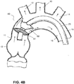
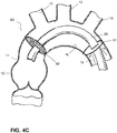
- the valve-filter device 60 has substantially flat components, as illustrated in FIGS. 4A-4D , that may be disk-shaped, for example circular, elliptical, or the like.
- the device of this embodiment comprises a first substantially flat portion or disk 61, 161 and a second substantially flat portion or disk 62, 162, said first and second portions concentrically aligned.
- the first disk 61, 161 is impermeable to blood and functions as the valve
- the second disk 62, 162 is permeable to blood but impermeable to emboli and functions as an embolic filter.
- the second disk 62, 162 may comprise a permeable membrane, constructed of the materials described above for the embodiments of FIGS.
- valve filter-device of FIGS. 4A-4C is designed so that blood may flow around the first disk 61, 161 which preferably is sufficiently flexible to fold downstream at least in part during systole and sufficiently stiff and elastic to regain its substantially flat configuration during diastole to minimize blood backflow. Arrows indicate direction of blood flow, and in FIGS. 4A and 4C illustrate how the valve may prevent back-flow during diastole.
- the first and second disk 61, 62 may have similar diameter and lie adjacent one another as illustrated in FIG. 4A .
- the first disk 61 may lie on top of the second disk 62, overlapping during diastole.
- FIG. 4A a small space is shown between the first and second disks 61, 62 for clarity of illustration.
- the first and second disks 61, 62 may be attached to each other in the center where they are connected to the delivery device 20, at points along the periphery (rims), or both.
- the first disk 61 which functions as the valve, may be fully open so that its rim contacts the vessel wall 16 during diastole to prevent backflow of blood.
- the first disk 61 may fold toward the center, for example toward the delivery device 20 sufficiently to allow blood flow through the vessel, as illustrated in FIG. 4B .
- the percutaneous valve-filter device may be placed between the sino-tubular junction 11 and branch point of the right brachial artery 12 as shown in FIGS. 4A and 4B .
- the valve filter device may be placed between the right brachial artery 12 and the left common carotid artery 13, or between the left common carotid artery 13 and the left subclavian artery 14, or further "downstream.”
- the first and second disk may be separated but located along a common longitudinal axis, as illustrated in FIG. 4C .
- the second disk 62 having the filtering function is located between the sino-tubular junction 11 and the right brachial artery 12.
- the second disk alternatively may be placed between the right brachial artery 12 and left common carotid artery 13, or between the left common carotid artery 13 and the left subclavian artery 14.
- the second disk 162 may have a radial inner portion 162a that is permeable to blood but impermeable to emboli and a radial outer portion 162b that is impermeable to blood.
- the first disk 161, impermeable to blood may lie adjacent to and overlap the radial inner portion 162a of the second disk 162 during diastole, closing the permeable radial inner portion 162a to limit backflow of blood (not shown), but slide distally along the delivery device 20 to open the valve-filter device, so that the blood may flow through the radial inner portion of the second disk, as illustrated in FIG. 4D .
- Arrows indicate direction of blood flow.
- the valve-filter device of this aspect of the embodiment includes a "stop" (not shown) on the delivery device, or lines (not shown) connecting the first disk 161 to the second disk 162, or comparable structure to limit the distance the first disk 161 slides along the delivery device 20 during systole.
- the first disk is attached at the center to the second disk, e.g., around the catheter, so that the first disk may flex during the systolic phase to allow blood to flow through the inner radial portion of the second disk.
- the comparative example of FIG. 4D may be positioned in the blood vessel similarly to the comparative example of FIGS. 4A and 4B .
- the size of the inner radial portion 162a is as large as the smallest radius required to permit blood flow through the vessel.
- the remainder of the second disk 162, i.e., the outer radial portion 162b, is flexible as to sizing, so as to allow the filter portion of the valve-filter device, i.e., the second disk 162 to fit in the blood vessel. It is well within the skill in the art to determine the appropriate percent cross-sectional area for a particular application.
- Suitable materials for the first and second disks of the comparative example of FIGS. 4A- 4D are as discussed above for other embodiments of the invention.
- the inner and outer radial portions 162a, 162b of the second disk 162 could be made of the same material (with the inner portion made permeable by mechanical or chemical means) or they may be made of different materials.
- the valve-filter device has a delivery configuration, in which the first (valve) disk 61, 161 and second (filter) disk 62, 162 are folded or wrapped around the delivery device 20.
- the valve-filter device may be self-expandable.
- the second disk may be self-expandable.
- the ring 142 and wires 144 of the embodiment of FIG. 2 control the diameter of the valve unit, which is also capable of reducing to near zero diameter.
- the valve and filter units or single unit valve-filter unit may be manually opened.
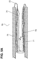
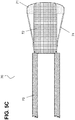
- FIGS. 5A-C A percutaneous temporary valve system 70 and a method of deploying the temporary valve according to the invention is illustrated in FIGS. 5A-C .
- the temporary valve system includes a temporary valve 71, central core 72, a plurality of lines 74, a sheath 75, and a pusher 80.
- the central core 72 is tubular with an open proximal end, for example with a cuff to provide a pushing surface for the pusher 80, and an open distal end facing (adjacent or non-adjacent) or attached to the valve 71.
- the valve 71 has an open center region large enough to accommodate a delivery device passing therethrough, and the edge of the valve 71 open center region may be attached to the distal end of the central core 72, or it may have a diameter and stiffness sufficient to allow the distal end of the central core 72 to support and maintain the position of the valve center during systole.
- the plurality of lines 74 connect the rim of the temporary valve 71 to the central core 72.
- Each of the plurality of lines 74 may be attached to the central core 72 by means known in the art, for example, gluing or bonding.
- the lines 74 may be attached to the valve 71 by similar means.
- the lines 74 are made of the same material as the valve 71. More preferably, the valve 71 and lines 74 are a unitary structure, constructed from a single mold with a polymer that includes the entire valve and lines, requiring no attachment.
- the temporary valve system 70 has a delivery configuration, in which the valve 71 and central core 72 are inverted, for example folded back on itself like a folded sock (with an open toe), and housed within the sheath 75, along with the lines 74, as shown in FIG. 5A .
- the central core 72 is preferably in direct continuity with the pusher 80, and is made of a material that is sufficiently flexible to allow it to invert on itself and into the sheath 75 when folded.
- the pusher 80 has an outer diameter that matches the inner diameter of the sheath 75 so that it can push the components contained within the sheath 75 out of the sheath.
- the temporary valve 71 will begin to function once the central core 72 and the temporary valve 71 have been pushed out of the sheath 75.
- the central core 72 preferably has a diameter large enough to accommodate a catheter carrying a permanent valve device or valve repair tool to pass through to deliver the permanent valve or repair tool to a site distal of the valve (and filter where used).
- the delivery catheter may be inserted through the sheath and out the open distal end of the central core 72 and through the temporary valve (and filter where used).
- the valve 71 of the temporary valve system has a jellyfish-like shape in its fully deployed configuration with a plurality of lines 74 that connect the rim of the valve 71 to the central core 72, for example near the proximal end of the central core 72, as illustrated in FIG. 5C .
- the lines 74 may be attached to the sheath 75 (not shown).
- the lines and valve are manufactured as a single piece, for example by molding polymer material.
- the lines 74 may be wires or strings attached to the valve 71, the wires or strings may be made of the same material as the valve 71.
- the lines 74 provide tension during diastole to control the diameter of the valve 71.
- the lines 74 may be pulled forward or backward to control the diameter of the valve.
- the valve 71 and central core 72 may be deployed by everting the valve and central core using a pusher 80.
- the pusher 80 may be, for example, a catheter.
- Each of the plurality of lines 74 are attached at a first end to the rim of the valve 71 and at a second end to a position on the central core 72, for example near the distal end 72b of the central core - distal end 72b of the central core 72 being the end furthest from the canopy of the temporary valve and the proximal end 72a of the central core 72 being attached to the canopy of the temporary valve 71.
- FIG. 5C illustrates a fully deployed temporary valve, with the central core extending down the center of the device.
- the temporary valve system of FIGS. 5A-5C may be used with any of the filter units described above, as illustrated in FIG. 6 .
- the temporary valve of FIGS. 5A-5C is deployed proximal of the left subclavian artery (see, e.g., element 14 of Fig. 1 ).
- the filter unit is preferably deployed between the right brachial artery and sino-tubular junction (e.g., elements 12 and 11 of Fig. 1 ) to maximize trapping of emboli.
- the temporary valve of the embodiment of FIG. 6 may be deployed near the filter unit or more proximally, for example proximal of the left subclavian artery (see element 14 of Fig. 1 ).
- the filter unit may be delivered and deployed using the delivery device used to deliver a permanent percutaneous valve device or valve repair tools.
- the central core 72 which is the backbone of the temporary valve, may be made of a flexible material, such as a braid or mesh.
- the central core 72 may be made of a biocompatible metal, such as for example Nitinol or other shape memory material, or it may be made of a biocompatible fabric, such as for example a polymeric material.
- polymeric materials include, for example, polyesters, such as Dacron and polyethylene terephthalate (PET), polytetrafluoroethylene (PTFE), polyurethanes, and nylon.
- PET polyethylene terephthalate
- PTFE polytetrafluoroethylene
- the central core 72 may be constrained by the sheath 75 (or, as shown in FIG.
- valve 71 is attached to the central core 72 by a plurality of lines 74, and may also be attached at its apex - at the proximal end.
- proximal refers to the end of the component oriented closer to the heart if the device is deployed in the aorta and “distal” refers to the end of the component oriented away from the heart if the device is deployed in the aorta.
- the temporary valve system 70 may be used with or without a filter unit 90.
- Filter unit 90 may have an umbrella-shaped canopy, as described in FIG. 2 (filter unit 150), or may be substantially flat, as described in FIGS. 4A-C (filter unit 62).
- Suitable materials for the temporary valve-filter device and temporary valve of the invention include fabrics, polymers, and tissue or other suitable biocompatible materials known in the art.
- Fabrics may include, e.g., PET, PTFE, ePTFE, polypropylene, and like materials.
- Polymers may include, e.g., PEBAX, silicone polycarbonate urethane, silicone, polyurethane, nylon, PET.
- Tissues may include bovine pericardium, porcine pericardium, or similar minimally immunogenic tissues.
- the percutaneous temporary valve-filter system of the present invention may further comprise a permanent prosthetic device, such as a replacement valve device, or a repair tool for the repair of calcified valve.
- the permanent device or repair tool may be delivered using a different, i.e., second, catheter having a diameter smaller than the diameter of catheter 20, the first catheter, shown FIGS. 1 , 2 , 3 , 4A , and 4B that permits it to pass through the catheter 20 to deliver the permanent device or repair tool to a site distal of the target site of the valve-filter or valve.
- valve-filter device may be compressed and folded into a delivery configuration, leaving a reduced cross sectional profile, and housed in a catheter during the navigation in the artery.
- the valve-filter device may be released from the catheter, for example, by push rods and/or pull wires that are commonly used in percutaneous procedures, for example, upon reaching the target site in the blood vessel,. After being released, the valve-filter device expands into its working configuration.
- ring 33 may expand into a circle to contact the aorta wall 16 while the material of canopy 31 renders the valve-filter into an open umbrella shape.
- Push rods and pull wires may also be used to help maintain the open umbrella shape of the valve-filter.
- ring 33, 153 and 253 may similarly expand so that the rim of the filter unit 150, 250 presses against the aorta wall 16 effectively sealing the vessel against the passage of emboli.
- the plurality of struts 145, 245 may open radially by a self-expansion mechanism during deployment, such as through the hinges 146 depicted in FIG.
- valve unit 140, 140a, 240 into a working configuration.
- a second delivery device having a smaller diameter may be threaded through the delivery device and extended past the valve-filter device to the site of permanent valve placement or valve repair.
- the device of FIGS. 4A-4D may be deployed in a similar manner.
- the temporary valve-filter system may further comprise a permanent percutaneous prosthetic valve, and the method may include deploying the permanent prosthetic device using the second delivery device, for example, an inner catheter, after deploying the temporary valve-filter.
- the system may further include a valve repair tool, and the method includes deploying the repair tool from the second delivery device and repairing a native valve after deploying the temporary valve-filter.
- the present disclosure also relates to a method of deploying a temporary valve.
- This method does not belong to the invention.
- the method comprises providing a sheath containing a folded central core and temporary valve comprising a body and a plurality of lines, wherein said plurality of lines connects a peripheral rim of said temporary valve to said central core, and said central core is attached to the sheath; and pushing said folded central core and temporary valve from the sheath using a pusher, thereby everting the central core and temporary valve into a deployed configuration.
- the lines may be attached to the sheath.
Claims (14)
- Perkutanes, temporäres Ventilsystem, aufweisend ein temporäres Ventil (71), einen zentralen Kern (72) und eine Ummantelung (75) zum Aufnehmen und Liefern des temporären Ventils (71) und zentralen Kerns (72);
dadurch gekennzeichnet, dass das temporäre Ventil (71) einen Körper und eine Mehrzahl an Strängen (74) aufweist, wobei jeder der Stränge (74) an einem ersten Ende mit einem Rand des Ventilkörpers und an einem zweiten Ende mit dem zentralen Kern (72) verbunden ist; wobei der zentrale Kern (72) mit dem Ende der Ummantelung (75) verbunden ist; wobei das temporäre Ventil (71) und der zentrale Kern (72) in einer umgekehrten Lieferkonfiguration innerhalb der Ummantelung (75) gefaltet sind und darauf ausgelegt sind, durch Drücken des zentralen Kerns (72) aus der Ummantelung (75) ausgebracht zu werden, wodurch das temporäre Ventil (71) und der zentrale Kern (72) umgestülpt werden. - System nach Anspruch 1, ferner aufweisend einen Drücker (80).
- System nach Anspruch 1 oder 2, wobei der zentrale Kern (72) eine Drückoberfläche beinhaltet.
- System nach einem der Ansprüche 1-3, wobei jedes von dem Ventil und dem zentralen Kern (72) einen offenen Mittelbereich aufweist.
- System nach einem der Ansprüche 1-4, wobei die Ummantelung (75) eine Filtereinheit (90) beinhaltet.
- System nach Anspruch 5, wobei die Filtereinheit (90) für Blut durchlässig, doch für Embolien undurchlässig ist, wobei das Ventilsystem darauf ausgelegt ist, gleichzeitig den Blutstrom zu regulieren und Embolien aufzufangen.
- System nach Anspruch 6, wobei die Filtereinheit (90) einen im Wesentlichen flachen Abschnitt aufweist, wobei der im Wesentlichen flache Abschnitt ein Material aufweist, das für Blut durchlässig, doch für Embolien undurchlässig ist.
- System nach Anspruch 7, wobei der im Wesentlichen flache Abschnitt einen inneren radialen Abschnitt und einen äußeren radialen Abschnitt beinhaltet, wobei der innere radiale Abschnitt das Material aufweist, das für Blut durchlässig, doch für Embolien undurchlässig ist, und wobei der äußere radiale Abschnitt ein Material aufweist, das für Blut undurchlässig ist.
- System nach Anspruch 6, wobei die Filtereinheit (90) zumindest ein Schirmdach aufweist; wobei das zumindest eine schirmförmige Dach eine Spitze, einen Sockel, eine offene Form in einer ausgebrachten Arbeitskonfiguration, und eine geschlossene Form in einer Lieferkonfiguration aufweist, wobei der Sockel einen Rand aufweist und das zumindest eine schirmförmige Dach in der ausgebrachten Arbeitskonfiguration eine konvexe Oberfläche und eine konkave Oberfläche aufweist.
- System nach Anspruch 6, wobei die Filtereinheit (90) eine Porosität in einem Bereich von 10-2000 µm im Durchmesser, vorzugsweise 50-500 µm im Durchmesser, besonders 80-200 µm im Durchmesser aufweist.
- System, aufweisend das Ventilsystem nach einem der Ansprüche 6-10 und eine erste Liefervorrichtung mit einem Lumen, wobei das Ventilsystem an der ersten Liefervorrichtung befestigt ist.
- System nach Anspruch 11, wobei das Lumen der ersten Liefervorrichtung einen Innendurchmesser aufweist, der ausreichend groß ist, damit eine zweite Liefervorrichtung hindurch verlaufen kann.
- System nach Anspruch 12, ferner aufweisend eine zweite Liefervorrichtung und eine perkutane Ventilvorrichtung zur Implantierung in ein Blutgefäß.
- System nach Anspruch 12, ferner aufweisend eine zweite Liefervorrichtung und ein Ventilreparaturwerkzeug zum Reparieren eines nativen Ventils.
Applications Claiming Priority (2)
| Application Number | Priority Date | Filing Date | Title |
|---|---|---|---|
| US201361784742P | 2013-03-14 | 2013-03-14 | |
| PCT/IB2014/001564 WO2014177935A2 (en) | 2013-03-14 | 2014-03-13 | Temporary valve and valve-filter |
Publications (2)
| Publication Number | Publication Date |
|---|---|
| EP2967807A2 EP2967807A2 (de) | 2016-01-20 |
| EP2967807B1 true EP2967807B1 (de) | 2020-07-22 |
Family
ID=51531093
Family Applications (1)
| Application Number | Title | Priority Date | Filing Date |
|---|---|---|---|
| EP14766197.9A Active EP2967807B1 (de) | 2013-03-14 | 2014-03-13 | Provisorische klappe |
Country Status (11)
| Country | Link |
|---|---|
| US (1) | US10595980B2 (de) |
| EP (1) | EP2967807B1 (de) |
| JP (2) | JP6361937B2 (de) |
| CN (2) | CN108852555A (de) |
| AU (3) | AU2014261117B2 (de) |
| CA (1) | CA2906446C (de) |
| ES (1) | ES2824628T3 (de) |
| HK (1) | HK1212582A1 (de) |
| IL (1) | IL240998B (de) |
| RU (3) | RU2017136961A (de) |
| WO (1) | WO2014177935A2 (de) |
Families Citing this family (44)
| Publication number | Priority date | Publication date | Assignee | Title |
|---|---|---|---|---|
| US8579964B2 (en) | 2010-05-05 | 2013-11-12 | Neovasc Inc. | Transcatheter mitral valve prosthesis |
| US9554897B2 (en) | 2011-04-28 | 2017-01-31 | Neovasc Tiara Inc. | Methods and apparatus for engaging a valve prosthesis with tissue |
| US9308087B2 (en) | 2011-04-28 | 2016-04-12 | Neovasc Tiara Inc. | Sequentially deployed transcatheter mitral valve prosthesis |
| US9345573B2 (en) | 2012-05-30 | 2016-05-24 | Neovasc Tiara Inc. | Methods and apparatus for loading a prosthesis onto a delivery system |
| US10595980B2 (en) | 2013-03-14 | 2020-03-24 | Valve Medical Ltd. | Temporary valve and valve-filter |
| US9572665B2 (en) | 2013-04-04 | 2017-02-21 | Neovasc Tiara Inc. | Methods and apparatus for delivering a prosthetic valve to a beating heart |
| EP3142598B1 (de) * | 2014-05-16 | 2020-07-08 | Veosource SA | Implantierbare selbstreinigende blutfilter |
| WO2015184450A1 (en) * | 2014-05-30 | 2015-12-03 | Cardiac Valve Solutions Llc | Temporary valve and filter on guide catheter |
| FR3021863A1 (fr) * | 2014-06-05 | 2015-12-11 | Bernard Pain | Dispositif d'introduction transcatheter dans la racine aortique au niveau de la jonction sino tubulaire |
| US9855143B2 (en) * | 2015-03-30 | 2018-01-02 | Hocor Cardiovascular Technologies Llc | Percutaneuous temporary aortic valve |
| US9592111B2 (en) | 2015-04-30 | 2017-03-14 | Mark Groh | Valve replacement devices |
| DE202017007326U1 (de) | 2016-01-29 | 2020-10-20 | Neovasc Tiara Inc. | Klappenprothese zum Verhindern einer Abflussobstruktion |
| WO2017197050A1 (en) * | 2016-05-10 | 2017-11-16 | Yale University | Aortic arch embolic protection device |
| CN109152908B (zh) | 2016-05-16 | 2021-06-08 | 瓣膜医学有限公司 | 反转的临时瓣膜鞘 |
| EP3541462A4 (de) | 2016-11-21 | 2020-06-17 | Neovasc Tiara Inc. | Verfahren und systeme zum schnellen rückzug eines transkatheter-herzklappenfreisetzungssystems |
| US11744692B2 (en) * | 2017-02-23 | 2023-09-05 | Boston Scientific Scimed, Inc. | Medical drain device |
| RU2661031C1 (ru) * | 2017-03-30 | 2018-07-11 | Закрытое Акционерное Общество Научно-Производственное Предприятие "Мединж" | Аортальный фильтр-клапан |
| WO2018187413A1 (en) * | 2017-04-05 | 2018-10-11 | Boston Scientific Scimed, Inc. | Emboli-capturing centering device |
| AU2018280236A1 (en) | 2017-06-07 | 2020-01-16 | Shifamed Holdings, Llc | Intravascular fluid movement devices, systems, and methods of use |
| WO2019036810A1 (en) | 2017-08-25 | 2019-02-28 | Neovasc Tiara Inc. | TRANSCATHETER MITRAL VALVULE PROSTHESIS WITH SEQUENTIAL DEPLOYMENT |
| KR20220071302A (ko) * | 2017-10-24 | 2022-05-31 | 버팔로 필터 엘엘씨 | 필터링 장치 및 방법 |
| JP7319266B2 (ja) | 2017-11-13 | 2023-08-01 | シファメド・ホールディングス・エルエルシー | 血管内流体移動デバイス、システム、および使用方法 |
| WO2019133494A1 (en) | 2017-12-28 | 2019-07-04 | Groh Mark | Embolic material capture catheter and related devices and methods |
| CN112004563A (zh) | 2018-02-01 | 2020-11-27 | 施菲姆德控股有限责任公司 | 血管内血泵以及使用和制造方法 |
| EP4218669A1 (de) * | 2018-03-27 | 2023-08-02 | Maduro Discovery, LLC | Zusatzgerät zur neuroprotektion während interventioneller prozeduren |
| US11596412B2 (en) | 2018-05-25 | 2023-03-07 | DePuy Synthes Products, Inc. | Aneurysm device and delivery system |
| US11382632B2 (en) * | 2018-06-27 | 2022-07-12 | Boston Scientific Scimed, Inc. | Vascular occlusion device |
| US11123077B2 (en) * | 2018-09-25 | 2021-09-21 | DePuy Synthes Products, Inc. | Intrasaccular device positioning and deployment system |
| CA3118599A1 (en) | 2018-11-08 | 2020-05-14 | Neovasc Tiara Inc. | Ventricular deployment of a transcatheter mitral valve prosthesis |
| WO2020168091A1 (en) * | 2019-02-13 | 2020-08-20 | Emboline, Inc. | Catheter with integrated embolic protection device |
| EP3946163A4 (de) | 2019-04-01 | 2022-12-21 | Neovasc Tiara Inc. | Steuerbar einsetzbare klappenprothese |
| AU2020271896B2 (en) | 2019-04-10 | 2022-10-13 | Neovasc Tiara Inc. | Prosthetic valve with natural blood flow |
| EP3972673A4 (de) | 2019-05-20 | 2023-06-07 | Neovasc Tiara Inc. | Einführungsvorrichtung mit hämostasemechanismus |
| IL294474B2 (en) | 2019-06-15 | 2023-09-01 | Maduro Discovery Llc | Catheter structure |
| AU2020295566B2 (en) | 2019-06-20 | 2023-07-20 | Neovasc Tiara Inc. | Low profile prosthetic mitral valve |
| EP3996797A4 (de) | 2019-07-12 | 2023-08-02 | Shifamed Holdings, LLC | Intravaskuläre blutpumpen und verfahren zur herstellung und verwendung |
| US11654275B2 (en) | 2019-07-22 | 2023-05-23 | Shifamed Holdings, Llc | Intravascular blood pumps with struts and methods of use and manufacture |
| US11724089B2 (en) | 2019-09-25 | 2023-08-15 | Shifamed Holdings, Llc | Intravascular blood pump systems and methods of use and control thereof |
| KR102492193B1 (ko) * | 2020-12-03 | 2023-01-26 | 고려대학교 산학협력단 | 흡입 및 위치조절이 가능한 위소매절제술용 위관 |
| KR102520440B1 (ko) * | 2020-12-15 | 2023-04-11 | 한양대학교 산학협력단 | 항역류 요관 스텐트 |
| US20220233204A1 (en) * | 2021-01-25 | 2022-07-28 | DePuy Synthes Products, Inc. | Anchoring and Non-Occluding Intravascular Device for Use During Clot Removal Via Aspiration and/or Mechanical Extraction Device |
| WO2022178324A1 (en) * | 2021-02-22 | 2022-08-25 | SummaCor, Inc. | Linear cardiac assist pulsatile pump |
| KR102605951B1 (ko) * | 2021-06-07 | 2023-11-24 | 주식회사 웨이브트리 | 복수배액용 내부배액관 |
| US20230381490A1 (en) * | 2022-05-26 | 2023-11-30 | Excision Medical, Inc. | Surgical system for managing blood flow during a surgical procedure |
Family Cites Families (35)
| Publication number | Priority date | Publication date | Assignee | Title |
|---|---|---|---|---|
| US3671979A (en) | 1969-09-23 | 1972-06-27 | Univ Utah | Catheter mounted artificial heart valve for implanting in close proximity to a defective natural heart valve |
| US4009717A (en) * | 1975-06-27 | 1977-03-01 | Allen Clayton H | Retaining fluids |
| US4109659A (en) | 1976-07-19 | 1978-08-29 | Mallinckrodt, Inc. | Evagination catheters |
| US4056854A (en) | 1976-09-28 | 1977-11-08 | The United States Of America As Represented By The Department Of Health, Education And Welfare | Aortic heart valve catheter |
| SU1424810A1 (ru) | 1986-12-22 | 1988-09-23 | Ереванский филиал Всесоюзного научного центра хирургии АМН СССР | Зажим дл наложени швов |
| WO1996001591A1 (en) * | 1994-07-08 | 1996-01-25 | Microvena Corporation | Method of forming medical devices; intravascular occlusion devices |
| US5800525A (en) * | 1997-06-04 | 1998-09-01 | Vascular Science, Inc. | Blood filter |
| US6051014A (en) * | 1998-10-13 | 2000-04-18 | Embol-X, Inc. | Percutaneous filtration catheter for valve repair surgery and methods of use |
| US6896690B1 (en) * | 2000-01-27 | 2005-05-24 | Viacor, Inc. | Cardiac valve procedure methods and devices |
| AU764886B2 (en) | 1999-01-27 | 2003-09-04 | Viacor Incorporated | Cardiac valve procedure methods and devices |
| US6692513B2 (en) * | 2000-06-30 | 2004-02-17 | Viacor, Inc. | Intravascular filter with debris entrapment mechanism |
| US7749245B2 (en) * | 2000-01-27 | 2010-07-06 | Medtronic, Inc. | Cardiac valve procedure methods and devices |
| JP4568116B2 (ja) | 2002-11-13 | 2010-10-27 | ビアカー・インコーポレーテッド | 心臓弁処置方法及び装置 |
| EP1472996B1 (de) * | 2003-04-30 | 2009-09-30 | Medtronic Vascular, Inc. | Perkutaneingesetzte provisorische Klappe |
| US7537600B2 (en) * | 2003-06-12 | 2009-05-26 | Boston Scientific Scimed, Inc. | Valved embolic protection filter |
| US20050075729A1 (en) * | 2003-10-06 | 2005-04-07 | Nguyen Tuoc Tan | Minimally invasive valve replacement system |
| US7604650B2 (en) * | 2003-10-06 | 2009-10-20 | 3F Therapeutics, Inc. | Method and assembly for distal embolic protection |
| US10219899B2 (en) * | 2004-04-23 | 2019-03-05 | Medtronic 3F Therapeutics, Inc. | Cardiac valve replacement systems |
| US7780725B2 (en) | 2004-06-16 | 2010-08-24 | Sadra Medical, Inc. | Everting heart valve |
| US7435257B2 (en) | 2004-05-05 | 2008-10-14 | Direct Flow Medical, Inc. | Methods of cardiac valve replacement using nonstented prosthetic valve |
| US8409237B2 (en) | 2004-05-27 | 2013-04-02 | Medtronic, Inc. | Emboli filter export system |
| US8252017B2 (en) * | 2005-10-18 | 2012-08-28 | Cook Medical Technologies Llc | Invertible filter for embolic protection |
| US20070149996A1 (en) * | 2005-12-28 | 2007-06-28 | Medtronic Vascular, Inc. | Low profile filter |
| US20070255394A1 (en) * | 2006-04-28 | 2007-11-01 | Medtronic, Inc. | Method and apparatus for cardiac valve replacement |
| CN101616639B (zh) * | 2007-03-20 | 2012-01-11 | Minvasys公司 | 用于带栓塞保护的支架输送的设备和方法 |
| JP2009178518A (ja) * | 2008-02-01 | 2009-08-13 | Nipro Corp | 医療用管状体、血栓捕捉部材回収用シース、血栓回収カテーテル及びバルーンカテーテル |
| WO2010026240A1 (en) | 2008-09-04 | 2010-03-11 | Karolinska Institutet Innovations Ab | Temporary embolic protection device and medical procedure for delivery thereof |
| US9402720B2 (en) | 2009-01-12 | 2016-08-02 | Valve Medical Ltd. | Modular percutaneous valve structure and delivery method |
| US8696698B2 (en) * | 2009-12-02 | 2014-04-15 | Surefire Medical, Inc. | Microvalve protection device and method of use for protection against embolization agent reflux |
| US8016872B2 (en) * | 2009-12-22 | 2011-09-13 | Cook Medical Technologies Llc | Deployment and dilation with an expandable roll sock delivery system |
| US9504562B2 (en) | 2010-01-12 | 2016-11-29 | Valve Medical Ltd. | Self-assembling modular percutaneous valve and methods of folding, assembly and delivery |
| US8512401B2 (en) | 2010-04-12 | 2013-08-20 | Medtronic, Inc. | Transcatheter prosthetic heart valve delivery system with funnel recapturing feature and method |
| KR20130076813A (ko) * | 2010-04-13 | 2013-07-08 | 액세스 포인트 테크놀로지스, 아이엔씨. | 색전 물질 절개 트랩핑 장치 |
| WO2012015825A2 (en) | 2010-07-27 | 2012-02-02 | Incept, Llc | Methods and apparatus for treating neurovascular venous outflow obstruction |
| US10595980B2 (en) | 2013-03-14 | 2020-03-24 | Valve Medical Ltd. | Temporary valve and valve-filter |
-
2014
- 2014-03-13 US US14/207,844 patent/US10595980B2/en active Active
- 2014-03-13 EP EP14766197.9A patent/EP2967807B1/de active Active
- 2014-03-13 JP JP2015562419A patent/JP6361937B2/ja active Active
- 2014-03-13 AU AU2014261117A patent/AU2014261117B2/en not_active Ceased
- 2014-03-13 RU RU2017136961A patent/RU2017136961A/ru not_active Application Discontinuation
- 2014-03-13 RU RU2015135241A patent/RU2634683C2/ru not_active IP Right Cessation
- 2014-03-13 WO PCT/IB2014/001564 patent/WO2014177935A2/en active Application Filing
- 2014-03-13 ES ES14766197T patent/ES2824628T3/es active Active
- 2014-03-13 CA CA2906446A patent/CA2906446C/en not_active Expired - Fee Related
- 2014-03-13 CN CN201810486495.1A patent/CN108852555A/zh active Pending
- 2014-03-13 CN CN201480014167.1A patent/CN105188604B/zh active Active
-
2015
- 2015-09-01 IL IL240998A patent/IL240998B/en active IP Right Grant
-
2016
- 2016-01-21 HK HK16100651.2A patent/HK1212582A1/zh unknown
-
2017
- 2017-06-19 AU AU2017204142A patent/AU2017204142B2/en not_active Ceased
-
2018
- 2018-06-12 JP JP2018111615A patent/JP6715882B2/ja active Active
- 2018-12-13 AU AU2018278941A patent/AU2018278941A1/en not_active Abandoned
-
2019
- 2019-05-29 RU RU2019116579A patent/RU2019116579A/ru unknown
Non-Patent Citations (1)
| Title |
|---|
| None * |
Also Published As
| Publication number | Publication date |
|---|---|
| EP2967807A2 (de) | 2016-01-20 |
| WO2014177935A3 (en) | 2015-03-19 |
| CN108852555A (zh) | 2018-11-23 |
| ES2824628T3 (es) | 2021-05-12 |
| US10595980B2 (en) | 2020-03-24 |
| AU2018278941A1 (en) | 2019-01-17 |
| AU2014261117A1 (en) | 2015-09-03 |
| WO2014177935A2 (en) | 2014-11-06 |
| CA2906446C (en) | 2019-11-26 |
| US20140277096A1 (en) | 2014-09-18 |
| JP2016510616A (ja) | 2016-04-11 |
| RU2015135241A (ru) | 2017-04-17 |
| CN105188604A (zh) | 2015-12-23 |
| AU2017204142A1 (en) | 2017-07-06 |
| JP2018167047A (ja) | 2018-11-01 |
| JP6715882B2 (ja) | 2020-07-01 |
| AU2017204142B2 (en) | 2019-01-03 |
| RU2017136961A3 (de) | 2019-02-15 |
| JP6361937B2 (ja) | 2018-07-25 |
| RU2634683C2 (ru) | 2017-11-02 |
| CN105188604B (zh) | 2018-06-19 |
| AU2014261117B2 (en) | 2017-03-30 |
| IL240998B (en) | 2021-05-31 |
| IL240998A0 (en) | 2015-11-30 |
| RU2019116579A (ru) | 2020-11-30 |
| CA2906446A1 (en) | 2014-11-06 |
| HK1212582A1 (zh) | 2016-06-17 |
| RU2017136961A (ru) | 2019-02-11 |
Similar Documents
| Publication | Publication Date | Title |
|---|---|---|
| AU2017204142B2 (en) | Temporary valve and valve-filter | |
| EP3458136B1 (de) | Temporäres blutventil mit umstülpbarer hülle | |
| CN108366856B (zh) | 用于心脏瓣膜假体的经导管植入的递送系统 | |
| CN108366857B (zh) | 具有作为用于自扩张假体的联接机构和展开机构的可收缩线材的递送系统 | |
| EP1472996B1 (de) | Perkutaneingesetzte provisorische Klappe | |
| EP2345380B1 (de) | Herzklappenverfahrensvorrichtungen | |
| US9192467B2 (en) | Valve prostheses | |
| US8951280B2 (en) | Cardiac valve procedure methods and devices | |
| CA2361670C (en) | Cardiac valve procedure methods and devices | |
| EP2967810B1 (de) | Embolieschutzvorrichtungen | |
| MX2010008171A (es) | Endoprotesis para valvulas cardiacas protesicas. |
Legal Events
| Date | Code | Title | Description |
|---|---|---|---|
| PUAI | Public reference made under article 153(3) epc to a published international application that has entered the european phase |
Free format text: ORIGINAL CODE: 0009012 |
|
| 17P | Request for examination filed |
Effective date: 20150828 |
|
| AK | Designated contracting states |
Kind code of ref document: A2 Designated state(s): AL AT BE BG CH CY CZ DE DK EE ES FI FR GB GR HR HU IE IS IT LI LT LU LV MC MK MT NL NO PL PT RO RS SE SI SK SM TR |
|
| AX | Request for extension of the european patent |
Extension state: BA ME |
|
| RIN1 | Information on inventor provided before grant (corrected) |
Inventor name: RICHTER, YORAM Inventor name: WEISZ, ETY Inventor name: SCHWARZ, BOAZ |
|
| REG | Reference to a national code |
Ref country code: HK Ref legal event code: DE Ref document number: 1212582 Country of ref document: HK |
|
| DAX | Request for extension of the european patent (deleted) | ||
| STAA | Information on the status of an ep patent application or granted ep patent |
Free format text: STATUS: EXAMINATION IS IN PROGRESS |
|
| 17Q | First examination report despatched |
Effective date: 20170808 |
|
| RIC1 | Information provided on ipc code assigned before grant |
Ipc: A61F 2/01 20060101AFI20191218BHEP Ipc: A61F 2/24 20060101ALN20191218BHEP Ipc: A61B 17/12 20060101ALI20191218BHEP |
|
| GRAP | Despatch of communication of intention to grant a patent |
Free format text: ORIGINAL CODE: EPIDOSNIGR1 |
|
| STAA | Information on the status of an ep patent application or granted ep patent |
Free format text: STATUS: GRANT OF PATENT IS INTENDED |
|
| RIC1 | Information provided on ipc code assigned before grant |
Ipc: A61F 2/24 20060101ALN20200121BHEP Ipc: A61B 17/12 20060101ALI20200121BHEP Ipc: A61F 2/01 20060101AFI20200121BHEP |
|
| INTG | Intention to grant announced |
Effective date: 20200205 |
|
| RIC1 | Information provided on ipc code assigned before grant |
Ipc: A61F 2/01 20060101AFI20200127BHEP Ipc: A61B 17/12 20060101ALI20200127BHEP Ipc: A61F 2/24 20060101ALN20200127BHEP |
|
| GRAS | Grant fee paid |
Free format text: ORIGINAL CODE: EPIDOSNIGR3 |
|
| GRAA | (expected) grant |
Free format text: ORIGINAL CODE: 0009210 |
|
| STAA | Information on the status of an ep patent application or granted ep patent |
Free format text: STATUS: THE PATENT HAS BEEN GRANTED |
|
| AK | Designated contracting states |
Kind code of ref document: B1 Designated state(s): AL AT BE BG CH CY CZ DE DK EE ES FI FR GB GR HR HU IE IS IT LI LT LU LV MC MK MT NL NO PL PT RO RS SE SI SK SM TR |
|
| REG | Reference to a national code |
Ref country code: GB Ref legal event code: FG4D |
|
| REG | Reference to a national code |
Ref country code: CH Ref legal event code: EP |
|
| REG | Reference to a national code |
Ref country code: DE Ref legal event code: R096 Ref document number: 602014068024 Country of ref document: DE |
|
| REG | Reference to a national code |
Ref country code: AT Ref legal event code: REF Ref document number: 1292667 Country of ref document: AT Kind code of ref document: T Effective date: 20200815 |
|
| REG | Reference to a national code |
Ref country code: IE Ref legal event code: FG4D |
|
| REG | Reference to a national code |
Ref country code: NL Ref legal event code: FP |
|
| REG | Reference to a national code |
Ref country code: LT Ref legal event code: MG4D |
|
| REG | Reference to a national code |
Ref country code: AT Ref legal event code: MK05 Ref document number: 1292667 Country of ref document: AT Kind code of ref document: T Effective date: 20200722 |
|
| PG25 | Lapsed in a contracting state [announced via postgrant information from national office to epo] |
Ref country code: GR Free format text: LAPSE BECAUSE OF FAILURE TO SUBMIT A TRANSLATION OF THE DESCRIPTION OR TO PAY THE FEE WITHIN THE PRESCRIBED TIME-LIMIT Effective date: 20201023 Ref country code: NO Free format text: LAPSE BECAUSE OF FAILURE TO SUBMIT A TRANSLATION OF THE DESCRIPTION OR TO PAY THE FEE WITHIN THE PRESCRIBED TIME-LIMIT Effective date: 20201022 Ref country code: BG Free format text: LAPSE BECAUSE OF FAILURE TO SUBMIT A TRANSLATION OF THE DESCRIPTION OR TO PAY THE FEE WITHIN THE PRESCRIBED TIME-LIMIT Effective date: 20201022 Ref country code: HR Free format text: LAPSE BECAUSE OF FAILURE TO SUBMIT A TRANSLATION OF THE DESCRIPTION OR TO PAY THE FEE WITHIN THE PRESCRIBED TIME-LIMIT Effective date: 20200722 Ref country code: SE Free format text: LAPSE BECAUSE OF FAILURE TO SUBMIT A TRANSLATION OF THE DESCRIPTION OR TO PAY THE FEE WITHIN THE PRESCRIBED TIME-LIMIT Effective date: 20200722 Ref country code: FI Free format text: LAPSE BECAUSE OF FAILURE TO SUBMIT A TRANSLATION OF THE DESCRIPTION OR TO PAY THE FEE WITHIN THE PRESCRIBED TIME-LIMIT Effective date: 20200722 Ref country code: LT Free format text: LAPSE BECAUSE OF FAILURE TO SUBMIT A TRANSLATION OF THE DESCRIPTION OR TO PAY THE FEE WITHIN THE PRESCRIBED TIME-LIMIT Effective date: 20200722 Ref country code: PT Free format text: LAPSE BECAUSE OF FAILURE TO SUBMIT A TRANSLATION OF THE DESCRIPTION OR TO PAY THE FEE WITHIN THE PRESCRIBED TIME-LIMIT Effective date: 20201123 Ref country code: AT Free format text: LAPSE BECAUSE OF FAILURE TO SUBMIT A TRANSLATION OF THE DESCRIPTION OR TO PAY THE FEE WITHIN THE PRESCRIBED TIME-LIMIT Effective date: 20200722 |
|
| PG25 | Lapsed in a contracting state [announced via postgrant information from national office to epo] |
Ref country code: PL Free format text: LAPSE BECAUSE OF FAILURE TO SUBMIT A TRANSLATION OF THE DESCRIPTION OR TO PAY THE FEE WITHIN THE PRESCRIBED TIME-LIMIT Effective date: 20200722 Ref country code: RS Free format text: LAPSE BECAUSE OF FAILURE TO SUBMIT A TRANSLATION OF THE DESCRIPTION OR TO PAY THE FEE WITHIN THE PRESCRIBED TIME-LIMIT Effective date: 20200722 Ref country code: LV Free format text: LAPSE BECAUSE OF FAILURE TO SUBMIT A TRANSLATION OF THE DESCRIPTION OR TO PAY THE FEE WITHIN THE PRESCRIBED TIME-LIMIT Effective date: 20200722 Ref country code: IS Free format text: LAPSE BECAUSE OF FAILURE TO SUBMIT A TRANSLATION OF THE DESCRIPTION OR TO PAY THE FEE WITHIN THE PRESCRIBED TIME-LIMIT Effective date: 20201122 |
|
| REG | Reference to a national code |
Ref country code: DE Ref legal event code: R097 Ref document number: 602014068024 Country of ref document: DE |
|
| PG25 | Lapsed in a contracting state [announced via postgrant information from national office to epo] |
Ref country code: CZ Free format text: LAPSE BECAUSE OF FAILURE TO SUBMIT A TRANSLATION OF THE DESCRIPTION OR TO PAY THE FEE WITHIN THE PRESCRIBED TIME-LIMIT Effective date: 20200722 Ref country code: DK Free format text: LAPSE BECAUSE OF FAILURE TO SUBMIT A TRANSLATION OF THE DESCRIPTION OR TO PAY THE FEE WITHIN THE PRESCRIBED TIME-LIMIT Effective date: 20200722 Ref country code: EE Free format text: LAPSE BECAUSE OF FAILURE TO SUBMIT A TRANSLATION OF THE DESCRIPTION OR TO PAY THE FEE WITHIN THE PRESCRIBED TIME-LIMIT Effective date: 20200722 Ref country code: RO Free format text: LAPSE BECAUSE OF FAILURE TO SUBMIT A TRANSLATION OF THE DESCRIPTION OR TO PAY THE FEE WITHIN THE PRESCRIBED TIME-LIMIT Effective date: 20200722 Ref country code: SM Free format text: LAPSE BECAUSE OF FAILURE TO SUBMIT A TRANSLATION OF THE DESCRIPTION OR TO PAY THE FEE WITHIN THE PRESCRIBED TIME-LIMIT Effective date: 20200722 |
|
| REG | Reference to a national code |
Ref country code: ES Ref legal event code: FG2A Ref document number: 2824628 Country of ref document: ES Kind code of ref document: T3 Effective date: 20210512 |
|
| PLBE | No opposition filed within time limit |
Free format text: ORIGINAL CODE: 0009261 |
|
| STAA | Information on the status of an ep patent application or granted ep patent |
Free format text: STATUS: NO OPPOSITION FILED WITHIN TIME LIMIT |
|
| PG25 | Lapsed in a contracting state [announced via postgrant information from national office to epo] |
Ref country code: AL Free format text: LAPSE BECAUSE OF FAILURE TO SUBMIT A TRANSLATION OF THE DESCRIPTION OR TO PAY THE FEE WITHIN THE PRESCRIBED TIME-LIMIT Effective date: 20200722 |
|
| 26N | No opposition filed |
Effective date: 20210423 |
|
| PG25 | Lapsed in a contracting state [announced via postgrant information from national office to epo] |
Ref country code: SK Free format text: LAPSE BECAUSE OF FAILURE TO SUBMIT A TRANSLATION OF THE DESCRIPTION OR TO PAY THE FEE WITHIN THE PRESCRIBED TIME-LIMIT Effective date: 20200722 |
|
| PG25 | Lapsed in a contracting state [announced via postgrant information from national office to epo] |
Ref country code: SI Free format text: LAPSE BECAUSE OF FAILURE TO SUBMIT A TRANSLATION OF THE DESCRIPTION OR TO PAY THE FEE WITHIN THE PRESCRIBED TIME-LIMIT Effective date: 20200722 |
|
| REG | Reference to a national code |
Ref country code: DE Ref legal event code: R119 Ref document number: 602014068024 Country of ref document: DE |
|
| PG25 | Lapsed in a contracting state [announced via postgrant information from national office to epo] |
Ref country code: MC Free format text: LAPSE BECAUSE OF FAILURE TO SUBMIT A TRANSLATION OF THE DESCRIPTION OR TO PAY THE FEE WITHIN THE PRESCRIBED TIME-LIMIT Effective date: 20200722 |
|
| REG | Reference to a national code |
Ref country code: CH Ref legal event code: PL |
|
| REG | Reference to a national code |
Ref country code: BE Ref legal event code: MM Effective date: 20210331 |
|
| PG25 | Lapsed in a contracting state [announced via postgrant information from national office to epo] |
Ref country code: DE Free format text: LAPSE BECAUSE OF NON-PAYMENT OF DUE FEES Effective date: 20211001 Ref country code: LU Free format text: LAPSE BECAUSE OF NON-PAYMENT OF DUE FEES Effective date: 20210313 Ref country code: LI Free format text: LAPSE BECAUSE OF NON-PAYMENT OF DUE FEES Effective date: 20210331 Ref country code: CH Free format text: LAPSE BECAUSE OF NON-PAYMENT OF DUE FEES Effective date: 20210331 |
|
| PG25 | Lapsed in a contracting state [announced via postgrant information from national office to epo] |
Ref country code: BE Free format text: LAPSE BECAUSE OF NON-PAYMENT OF DUE FEES Effective date: 20210331 |
|
| PGFP | Annual fee paid to national office [announced via postgrant information from national office to epo] |
Ref country code: IE Payment date: 20230327 Year of fee payment: 10 Ref country code: FR Payment date: 20230327 Year of fee payment: 10 |
|
| PG25 | Lapsed in a contracting state [announced via postgrant information from national office to epo] |
Ref country code: HU Free format text: LAPSE BECAUSE OF FAILURE TO SUBMIT A TRANSLATION OF THE DESCRIPTION OR TO PAY THE FEE WITHIN THE PRESCRIBED TIME-LIMIT; INVALID AB INITIO Effective date: 20140313 |
|
| PGFP | Annual fee paid to national office [announced via postgrant information from national office to epo] |
Ref country code: IT Payment date: 20230321 Year of fee payment: 10 Ref country code: GB Payment date: 20230327 Year of fee payment: 10 |
|
| PG25 | Lapsed in a contracting state [announced via postgrant information from national office to epo] |
Ref country code: CY Free format text: LAPSE BECAUSE OF FAILURE TO SUBMIT A TRANSLATION OF THE DESCRIPTION OR TO PAY THE FEE WITHIN THE PRESCRIBED TIME-LIMIT Effective date: 20200722 |
|
| PGFP | Annual fee paid to national office [announced via postgrant information from national office to epo] |
Ref country code: NL Payment date: 20230326 Year of fee payment: 10 |
|
| PGFP | Annual fee paid to national office [announced via postgrant information from national office to epo] |
Ref country code: ES Payment date: 20230403 Year of fee payment: 10 |
|
| PGFP | Annual fee paid to national office [announced via postgrant information from national office to epo] |
Ref country code: NL Payment date: 20240326 Year of fee payment: 11 Ref country code: IE Payment date: 20240327 Year of fee payment: 11 |