EP2967718B1 - Pince de décalage - Google Patents
Pince de décalage Download PDFInfo
- Publication number
- EP2967718B1 EP2967718B1 EP14706460.4A EP14706460A EP2967718B1 EP 2967718 B1 EP2967718 B1 EP 2967718B1 EP 14706460 A EP14706460 A EP 14706460A EP 2967718 B1 EP2967718 B1 EP 2967718B1
- Authority
- EP
- European Patent Office
- Prior art keywords
- forceps
- working arm
- working arms
- working
- configuration
- Prior art date
- Legal status (The legal status is an assumption and is not a legal conclusion. Google has not performed a legal analysis and makes no representation as to the accuracy of the status listed.)
- Not-in-force
Links
Images


Classifications
-
- A—HUMAN NECESSITIES
- A61—MEDICAL OR VETERINARY SCIENCE; HYGIENE
- A61B—DIAGNOSIS; SURGERY; IDENTIFICATION
- A61B18/00—Surgical instruments, devices or methods for transferring non-mechanical forms of energy to or from the body
- A61B18/04—Surgical instruments, devices or methods for transferring non-mechanical forms of energy to or from the body by heating
- A61B18/12—Surgical instruments, devices or methods for transferring non-mechanical forms of energy to or from the body by heating by passing a current through the tissue to be heated, e.g. high-frequency current
- A61B18/14—Probes or electrodes therefor
- A61B18/1442—Probes having pivoting end effectors, e.g. forceps
-
- A—HUMAN NECESSITIES
- A61—MEDICAL OR VETERINARY SCIENCE; HYGIENE
- A61B—DIAGNOSIS; SURGERY; IDENTIFICATION
- A61B18/00—Surgical instruments, devices or methods for transferring non-mechanical forms of energy to or from the body
- A61B18/04—Surgical instruments, devices or methods for transferring non-mechanical forms of energy to or from the body by heating
- A61B18/08—Surgical instruments, devices or methods for transferring non-mechanical forms of energy to or from the body by heating by means of electrically-heated probes
- A61B18/082—Probes or electrodes therefor
- A61B18/085—Forceps, scissors
-
- A—HUMAN NECESSITIES
- A61—MEDICAL OR VETERINARY SCIENCE; HYGIENE
- A61B—DIAGNOSIS; SURGERY; IDENTIFICATION
- A61B18/00—Surgical instruments, devices or methods for transferring non-mechanical forms of energy to or from the body
- A61B2018/00571—Surgical instruments, devices or methods for transferring non-mechanical forms of energy to or from the body for achieving a particular surgical effect
- A61B2018/00589—Coagulation
-
- A—HUMAN NECESSITIES
- A61—MEDICAL OR VETERINARY SCIENCE; HYGIENE
- A61B—DIAGNOSIS; SURGERY; IDENTIFICATION
- A61B18/00—Surgical instruments, devices or methods for transferring non-mechanical forms of energy to or from the body
- A61B2018/00571—Surgical instruments, devices or methods for transferring non-mechanical forms of energy to or from the body for achieving a particular surgical effect
- A61B2018/00595—Cauterization
-
- A—HUMAN NECESSITIES
- A61—MEDICAL OR VETERINARY SCIENCE; HYGIENE
- A61B—DIAGNOSIS; SURGERY; IDENTIFICATION
- A61B18/00—Surgical instruments, devices or methods for transferring non-mechanical forms of energy to or from the body
- A61B18/04—Surgical instruments, devices or methods for transferring non-mechanical forms of energy to or from the body by heating
- A61B18/12—Surgical instruments, devices or methods for transferring non-mechanical forms of energy to or from the body by heating by passing a current through the tissue to be heated, e.g. high-frequency current
- A61B18/14—Probes or electrodes therefor
- A61B18/1442—Probes having pivoting end effectors, e.g. forceps
- A61B2018/146—Scissors
-
- A—HUMAN NECESSITIES
- A61—MEDICAL OR VETERINARY SCIENCE; HYGIENE
- A61B—DIAGNOSIS; SURGERY; IDENTIFICATION
- A61B18/00—Surgical instruments, devices or methods for transferring non-mechanical forms of energy to or from the body
- A61B18/04—Surgical instruments, devices or methods for transferring non-mechanical forms of energy to or from the body by heating
- A61B18/12—Surgical instruments, devices or methods for transferring non-mechanical forms of energy to or from the body by heating by passing a current through the tissue to be heated, e.g. high-frequency current
- A61B18/14—Probes or electrodes therefor
- A61B18/1442—Probes having pivoting end effectors, e.g. forceps
- A61B2018/1462—Tweezers
-
- A—HUMAN NECESSITIES
- A61—MEDICAL OR VETERINARY SCIENCE; HYGIENE
- A61B—DIAGNOSIS; SURGERY; IDENTIFICATION
- A61B18/00—Surgical instruments, devices or methods for transferring non-mechanical forms of energy to or from the body
- A61B18/04—Surgical instruments, devices or methods for transferring non-mechanical forms of energy to or from the body by heating
- A61B18/12—Surgical instruments, devices or methods for transferring non-mechanical forms of energy to or from the body by heating by passing a current through the tissue to be heated, e.g. high-frequency current
- A61B18/14—Probes or electrodes therefor
- A61B18/16—Indifferent or passive electrodes for grounding
- A61B2018/167—Passive electrodes capacitively coupled to the skin
Definitions
- the present teachings generally relate to forceps that include opposing working arms that are aligned in some configurations, offset or askew in all and/or some configurations, or a combination of both.
- electrosurgical devices have stand-alone monopolar capabilities or bipolar capabilities.
- a surgeon before a procedure begins may select either a device with monopolar capabilities or a device with bipolar capabilities and the surgeon can use the device to apply either monopolar power or bipolar power.
- the surgeon may use either the device that supplies monopolar power to perform the procedure or switch to a device with bipolar capabilities. Both of these devices may be used to perform the procedure, however, switching between devices and/or using a device that may be better suited for a different purpose may disturb the procedure flow, cause unnecessary delays in the procedure, and in some cases result in less than optimal energy sources being used.
- electrosurgical devices are connected to a generator that produces a therapy signal and provides power to the electrosurgical device so that a therapy current is produced.
- the therapy currents that may be used are limited by the generator and thus if the generator is only capable of producing a single therapy current then only one therapy current can be applied through the electrosurgical device.
- a generator may be capable of producing two therapy circuits, but the electrosurgical device may only be capable of controlling and applying a single therapy current. Thus, the electrosurgical device may only apply a single therapy current.
- U.S. Patent No 5,810,805 teaches an electrosurgical instrument with a scissor-type device having two working arms, which can be reconfigured into a scalpel-type device by axially moving one of the working arms away from the other.
- an electrosurgical device that may be switched between a first electrosurgical configuration (e.g., a bipolar configuration) and a second electrosurgical configuration (e.g., a monopolar configuration) with one hand so that a user can easily perform a desired task without the need to disrupt the flow of a procedure. It would be attractive to have an electrosurgical device that may be used in open surgery as forceps and may be used for electrical cutting and/or hemostasis. What is needed is an electrosurgical device that can be switched between a gripping configuration and a cutting configuration without additional parts. It would be attractive to have an electrosurgical device that includes bipolar configuration and a monpolar configuration by mechanically reconfiguring forceps.
- a first electrosurgical configuration e.g., a bipolar configuration
- a second electrosurgical configuration e.g., a monopolar configuration
- an electrosurgical device comprising: forceps including: (i) a first working arm having a contact surface and (ii) a second working arm having a contact surface; wherein the forceps has a first electrical configuration where the contact surface of the first working arm and the contact surface of the second working arm are substantially opposite each other so that the contact surfaces of the forceps can be used to grip an item between the working arms and so that the forceps is configured to deliver a first therapy current through the first working arm, the second working arm, or both; and wherein the forceps has second electrical configuration where the contact surface of the first working arm and the contact surface of the second working arm are askew relative to each other and an electrode edge is formed on at least one side of the forceps so that a second therapy current extends from the electrode edge.
- an electrosurgical device comprising: forceps including:(i) a first working arm having a contact surface and (ii) a second working arm having a contact surface; wherein the forceps has a first configuration where the contact surface of the first working arm and the contact surface of the second working arm are substantially opposite each other so that the contact surfaces of the forceps can be used to grip an item between the working arms and so that the forceps is configured to deliver a first therapy current through the first working arm, the second working arm, or both; and wherein the forceps has a second configuration where the contact surface of the first working arm and the contact surface of the second working arm are askew relative to each other when the contact surfaces are brought into contact and an edge is formed on at least one side of the forceps so that the forceps is configured to cut tissue with the edge.
- an electrosurgical device comprising: forceps including: a first working arm having a contact surface and a second working arm having a contact surface; wherein the forceps have a bipolar position where the contact surface of the first working arm and the contact surface of the second working arm are substantially opposite each other so that the contact surfaces of the forceps can be used to grip an item between the working arms and so that a therapy current can be passed between the first working arm and the second working arm through the item; and wherein the forceps have a monopolar position where the contact surface of the first working arm and the contact surface of the second working arm are askew relative to each other and an electrode edge is formed on at least one side of the forceps so that the therapy current extends from the electrode edge.
- the present teachings further provide: a method comprising: (a) providing an electrosurgical device including: (i) a first working arm and (ii) a second working arm; (b) moving the first working arm and the second working arm towards each other so that the first working arm and the second working arm are forceps and are configured in a bipolar configuration so that a therapy current can pass between the first working arm and the second working arm; and (c) configuring the first working arm and the second working so that the first working arm and the second working arm are askew relative to each other forming a monopolar configuration.
- the teachings herein provide an electrosurgical device that may be switched between a first electrosurgical configuration (e.g., a bipolar configuration) and a second electrosurgical configuration (e.g., a monopolar configuration) with one hand so that a user can easily perform a desired task without the need to disrupt the flow of a procedure.
- the teachings herein provide an electrosurgical device that may be used in open surgery as forceps and may be used for electrical cutting and/or hemostasis.
- the teachings herein provide an electrosurgical device that can be switched between a gripping configuration and a cutting configuration without additional parts.
- the teachings herein provide an electrosurgical device that includes bipolar configuration and a monopolar configuration by mechanically reconfiguring forceps.
- the present teachings relate to an electrosurgical device.
- the present teachings relate to an electrosurgical device and associated componentry that form an electrosurgical system.
- the electrosurgical system may be any system that includes one or more of the devices taught herein.
- the electrical surgical system includes at least an electrosurgical device.
- the electrosurgical system includes an electrosurgical device that is electrically connected to a generator.
- the electrosurgical system may include one or more handpieces as taught herein, one or more ground pads, one or more generators, one or more electrosurgical devices, one or more adjacent handpiece components, or a combination thereof and the teachings herein of each device which are incorporated into the electrosurgical system.
- the electrosurgical device may be any device that may be used by a surgeon to perform a surgical procedure.
- the electrosurgical device may be any device that may be switched between two or more configurations, two or more states, or both.
- the electrosurgical device may be switched between a monopolar configuration, a bipolar configuration, or a combination of both.
- the electrosurgical device may be any device that may be switched between two or more configurations with one hand so that a user may switch between the configurations without the need for a second hand, without disrupting the procedure, or both.
- the electrosurgical device may be any device and/or configuration that may be used ambidextrously, ambidextrously switched between configurations, or both.
- the electrosurgical device may be used to cut, perform hemostasis, coagulate, desiccate, fulgrate, electrocautery, or a combination thereof.
- the electrosurgical device may be any device that includes bipolar capabilities, monopolar capabilities, non-electrosurgical capabilities, or a combination thereof.
- the electrosurgical device may be used in open surgery.
- the electrosurgical device may be used for non-electrosurgical purposes.
- the electrosurgical device may be used as forceps, tweezers, or both that may be used to grip an object, an organ, a vein, skin, tissue, a feature of interest, the like, or a combination thereof.
- the electrosurgical device may be used to cut, as a scalpel, or both.
- the electrosurgical device may include a handpiece and a generator.
- the electrosurgical device may have one or more therapy signals that extend between the handpiece and the generator.
- the one or more therapy signals may be a signal, power, continuity, current, voltage, or a combination thereof.
- the one or more therapy signals may extend from the handpiece to the generator or vice versa.
- the one or more therapy signals may be formed by the handpiece, formed by the generator, or both.
- the electrosurgical therapy signals may be a therapy current.
- the electrosurgical therapy signals may provide a signal so that one or more therapy currents are produced and the therapy currents may be used for electrosurgery.
- the electrosurgical therapy signal may be a monopolar therapy signal, a bipolar therapy signal, or both.
- the electrosurgical therapy signal may be a monopolar generator signal, a bipolar generator signal, or both.
- the monopolar therapy signal may be any signal that has a voltage differential between a return port and an active port in the generator.
- the monopolar therapy signal may be any signal that when applied by the electrosurgical device extends: from one pole of an electrosurgical device to another pole located at a remote location, off of the electrosurgical device (e.g., from the handpiece to a location separate from the handpiece), off of the handpiece, from an edge electrode, or a combination thereof.
- the bipolar therapy signal may be any signal that has a voltage differential between two leads that are connected to the electrosurgical device, that are located in the generator, or both.
- the bipolar therapy signal may be any signal that when applied by the electrosurgical device extends from one component of a handpiece to another component of the handpiece (e.g., between two working arms, from two edge electrodes, or both).
- the therapy signal may be generated and conducted from the handpiece to the generator or vice versa.
- the generator may be any device that supplies: power, voltage, a therapy current, control signals, an electrosurgical therapy signal, electrically reconfigures itself in response to a signal from the user and/or mechanical reconfiguration by the user, physically reconfigures in response to adjustments by the user, current, or a combination thereof.
- the generator may be any device that may be electrically connected to a handpiece to provide and/or receive electrosurgical therapy signals, power, therapy current, voltage, or a combination thereof.
- the generator may be capable of producing only a single therapy current.
- the single therapy current may be supplied to the electrosurgical device, and the mechanical configuration (e.g., the working arms being aligned, skewed, or a position therebetween) of the electrosurgical device may determine the type of therapy current applied (e.g., bipolar energy, monopolar energy, or both).
- the generator may be capable of producing two therapy currents.
- the generator may be capable of producing a plurality of therapy signals.
- the generator may include two or more power connections or three or more power connections.
- the power connections may be any port in the generator so that one or more power connectors of the handpiece may be plugged into so that power, control signals, therapy currents, voltage, or a combination thereof are supplied to the electrosurgical device.
- the generator may include one or more switches that may be switched between one or more of the power connections so that power, signals, or both may be selectively applied to the electrosurgical device based upon a desired configuration of the electrosurgical device.
- the generator may include a central processing unit (CPU).
- the CPU may electrically reconfigure the electrosurgical device without the need for physical reconfiguration.
- the CPU may be any device that provides power, signals, electrical reconfiguration, a switch between two or more therapy currents, a switch between two or more configurations, a switch between two or more therapy signals, or a combination thereof to the electrosurgical device so that the electrosurgical device may be used to perform a desired function as is discussed herein.
- the CPU may be used to switch the electrosurgical device between a first electrosurgical configuration, a second electrosurgical configuration, a third electrosurgical configuration, a monopolar configuration, a bipolar configuration, a non-electrosurgical configuration, or a combination thereof.
- the first therapy current may be monopolar energy and/or monopolar current.
- the first therapy current is bipolar energy and/or bipolar current.
- Bipolar energy may be any power source that during application extends from one pole of an electrosurgical device to another pole on the electrosurgical device.
- bipolar energy is energy that extends from one component on the forceps to another component on the forceps.
- between two physically connected components of the forceps For example, energy that extends between two separated working arms on the handpiece is bipolar energy.
- the first electrosurgical configuration may be deactivated and a second electrosurgical configuration activated.
- the second electrosurgical configuration may provide a second therapy current.
- the second therapy current may be bipolar energy (e.g., bipolar current or bipolar power).
- the second therapy current may be monopolar energy (e.g., monopolar current or monopolar power).
- Monopolar energy may be any power source that during application extends from one pole of an electrosurgical device to another pole, located at a remote location, off of the electrosurgical device, off the forceps, or a combination thereof.
- -monopolar energy is energy that extends from one component of the forceps to a component that is not physically part of the forceps.
- energy that extends from one or both working arms to a remote electrode is monopolar energy.
- a remote electrode e.g., ground pad
- the second electrosurgical configuration, the first electrosurgical configuration, or both may be reconfigured into a third electrosurgical configuration.
- the third electrosurgical configuration may be any electrosurgical configuration, a non-electrosurgical configuration, or both so that the electrosurgical device may be used to perform a procedure.
- the third electrosurgical configuration is a non-electrosurgical configuration.
- the non-electrosurgical configuration may be any configuration where power is not supplied to the forceps, the two or more working arms, or a combination thereof.
- the non-electrosurgical configuration may be used when the electrosurgical device is being used as forceps, tweezers, a clamp, Kelley hemostat forceps, scalpel, or a combination thereof.
- the working arms may be mobile.
- the working arms are immobilized in the non-electrosurgical configuration.
- the therapy current may not pass through the forceps, the working arms, the electrosurgical device, or a combination thereof.
- the therapy current that extends through the forceps may be effected by a signal and/or current from the generator; a forceps position (e.g., first position, second position, third position, etc...); or a combination thereof.
- the therapy current may be monopolar energy when the working arms are in the second position.
- the therapy current may be bipolar energy when the working arms are in the second position.
- the therapy current may be a bipolar energy when the electrosurgical is in the first position.
- the first electrosurgical configuration, second electrosurgical configuration, and third electrosurgical configuration may be any configuration that may perform one or more of the functions as discussed herein for the monopolar configuration, bipolar configuration, and non-electrosurgical configuration and each of those functions are incorporated herein.
- the first electrosurgical configuration is a bipolar configuration
- the second electrosurgical configuration is a monopolar configuration
- the third electrosurgical configuration is a non-electrosurgical configuration.
- the forceps when in a monopolar configuration may supply power through a handpiece component (e.g., a pair of connected immobilized working arms) and a return electrode (e.g., that may be located at another location outside of the hand held portion of the electrosurgical device), through a handpiece component and an adjacent handpiece component, or both.
- the monopolar configuration may be any configuration where the electrosurgical device may be used to apply monopolar power.
- the monopolar configuration may be used to cut tissue, coagulate blood and/or fluids, electrical cutting, hemostasis, apply power to a large area, or a combination thereof.
- the monopolar configuration may be used to heat a specific area, heat an object between both electrodes, in contact with both electrodes, or a combination thereof.
- the monopolar electrosurgery may be used for less delicate procedures, less localized electrosurgery, or both when compared to bipolar electrosurgery.
- the device when in a bipolar configuration may supply power from one portion of the device to a second portion of the device so that the return path for the power is relatively short when compared to the monopolar configuration.
- the bipolar configuration may be any configuration where the electrosurgical device may be used to apply bipolar power.
- the forceps when in the bipolar configuration may supply power between two localized handpiece components such as two working arms.
- the bipolar configuration may be used to coagulate, for hemostasis, cutting, fulguration, or a combination thereof.
- the electrosurgical device may include two opposing working arms. The two opposing working arms may be configured as forceps.
- the forceps may be any forceps that may be used to grip, hold, squeeze, or a combination thereof one or more objects.
- the forceps may include one or more finger grips (i.e., configured like scissors) that may be used to move the forceps so that they may be used to grip one or more objects.
- the forceps may be free of finger grips and be actuated by direct pressure being applied to opposing sides of the forceps so that the forceps close and grip an object. More preferably, the forces are closed by direct pressure being applied to a back of a pair of working arms.
- the forceps include at least two working arms.
- the working arms may be any part of the electrosurgical device that may be used to grip, hold, squeeze, or a combination thereof an object when the object is between the two or more opposing working arms.
- the working arms may include one or more gripping features that may assist in gripping, holding, squeezing, or a combination thereof an object.
- the working arms may be movable between two or more positions. Preferably, the working arms are movable between at least a first position and a second position.
- the working arms may be movable between a bipolar configuration (e.g., first position) and a monopolar configuration (e.g., second position).
- the working arms may be movable between an opposing position and an askew position.
- the working arms in the first position may be electrically off, energized, one working arm may be energized, used as tweezers, or a combination thereof.
- the working arms in the second position may be electrically off, one or both of the working arms may be electrically disconnected, one or both of the working arms may be electrically connected, one working arm may be shorted by the other working arm, or a combination thereof. More preferably, in the second position one or both of the working arms are immobilized so that the working arms cannot be used a forceps.
- the working arms may be longitudinally static (e.g., along a length of the working arms) and moveable relative to each other (e.g., both laterally and rotationally).
- the working arms may be laterally moveable (e.g., at substantially a right angle to the longitudinal axis; however, this angle may change as one or both of the working arms are moved) and may be moveable relative to each other so that a gripping force may be created.
- the working arms may be rotatable around a longitudinal axis, rotational axis, or both individually, simultaneously, or both.
- the working arms may include a body and a tip, electrode edge, or both.
- the body may be any part of the working arm that assists in creating a gripping force, in connecting two opposing working arms together, or both.
- the body may be a majority (i.e., 60 percent or more, 70 percent or more, or even 80 percent or more) of a gripping region of a working arm.
- a connection region may be located between the two opposing bodies of the working arms so that substantially all of the connection regions of the body are in contact when the working arms are in a gripping configuration, a skewed configuration, or both.
- the body portion may be any part that grips a feature of interest, is connected to a tip, provides a connection point for a tip, or a combination thereof.
- Each body may include an axis that the working arms rotate about.
- the body may be partially and/or entirely made of an electrically conductive material, an insulative material, or both.
- the body may include one or more wires, one or more power connectors, or both that may extend through the body.
- the body may be any size and shape so that the body portion supports a tip, has a gripping portion, conducts electricity, may be used as forceps, or a combination thereof.
- the body may have a cross section that is square, rectangular, half-circle, half-oval, oblong, geometric (i.e., a known geometric shape), symmetrical, asymmetrical, includes steps, is linear, includes a bulbous portion, or a combination thereof.
- the body may include a contact surface, a contact region, a connection region, or a combination thereof.
- connection region may be any part of the body, the working arms, or both that secures the working arms together, the body portions together, or both.
- the connection region may be a region where two opposing working arms contact each other.
- the connection region may be a region where two opposing working arms lock together.
- the connection regions when in contact may prevent the working arms from moving relative to each other (e.g., rotating).
- the connection regions may be smooth, complementary to an opposing connection region, a tongue and groove, inter-fitted pieces, a projection and a recess, opposing projections, opposing recesses, or a combination thereof.
- the connection regions of the two working arms may be in contact in the bipolar configuration, monopolar configuration, non-electrosurgical configuration, or both.
- connection regions of the two working arms may be in contact only in the monopolar configuration.
- the connection region may be located on an opposite end of the body, the working arms, or both as a tip, a tip region, or both.
- the ends may be substantially parallel to a gripping direction when the working arms are moved towards each other.
- the tip extends from one side of a body and the connection region extends from an opposing side of the body.
- a tip region, a tip, or both of the working arms may extend beyond a body when the working arms are in the skewed configuration.
- the tip region, tip, or both may function to deliver current to a location of interest, to assist in gripping an object of interest, assist in moving an object of interest, form a cutting surface, or a combination thereof.
- the tip, tip region, or both may be an edge and/or side of the working arms.
- the tip and/or tip region may be an edge of the working arms that form a point in a cross section, a non-blunt surface, or both.
- the tip region may include a portion that is configured to assist in facilitating gripping, holding, squeezing, or a combination thereof.
- the tip region may be configured and/or moved to one or more electrosurgical configurations (e.g., a monopolar configuration, bipolar configuration, non-electrosurgical, or a combination thereof).
- the tip region may include teeth, serrations, mouse teeth, be free of teeth (i.e., smooth), or a combination thereof.
- the tip region may be fully and/or partially insulated.
- the tip region includes insulation on the non-contact portions of the working arms so that electrosurgical energy is not transferred through incidental contact.
- the tip may extend beyond a body of the working arms so that the tip is exposed and may be used for cutting, applying a therapy current, or both.
- the tip, tip region, or both may be any size and shape so that the tip may be used for cutting, applying a therapy current, or both.
- the tip may be blunt, sharp, serrated, smooth, rounded, angled, smaller than the body portion, shorter than the body portion, longer than the body portion, thinner than the body portion, of a combination thereof.
- the tip may not be able to cut tissue (e.g., be blunt).
- the tip region may be an edge electrode, may form an edge electrode, may be part of an edge electrode, or a combination thereof.
- the edge electrode may be any part of the forceps, the working arms, or both that may create a cutting edge, an edge for applying a therapy current, or both.
- the edge may function as a mechanical blade (e.g., a blade, scalpel, surgical scalpel, or a combination thereof).
- the edge electrode may be a point (when viewed in a cross-section) and/or plane for applying power, a point and/or plane for mechanical cutting, a portion of one working arm that extends past an opposing working arm and/or opposing body portion in one or more configurations, or a combination thereof.
- the edge electrode may be any part of the working arms that extends beyond an opposing working arm and/or body.
- the edge electrode may be an active portion and/or include an active portion.
- the edge electrode may include an active portion and an inactive portion (i.e., an insulated portion).
- the active portion may be any portion of the device that may be used to apply power, a therapy current, or both.
- the active portion may be the same portion as the contact regions of the forceps. Thus, for example, when tissue is grasped between the contact portions of the forceps, power may be supplied to the tissue through this contact portion.
- the active portion of the working arms preferably is between the two opposing working arms, the active portion during a monopolar extends from a side and/or edge of one or both working arms, or both.
- the only exposed active portion may be found at the edge electrode, the tip, a tip region, a contact region, a contact surface, or a combination thereof.
- at least the edge electrode includes an exposed active portion.
- the active portions may be substantially surrounded by inactive portions or portions that are insulated.
- the inactive portion may be any portion that does not supply power, that is insulated, or both.
- the inactive portion may be any portion that may prevent a transfer power through incidental contact and thus are insulated so that an incidental transfer of power does not occur.
- an outside of the working arms may be coated with an insulating material so that if the working arms accidentally contact tissue proximate to the tissue of interest the proximate tissue is not subjected to a transfer of power.
- the body may be partially, substantially entirely, or entirely covered with inactive material, be inactive, or both.
- the inactive portion and the active portion may be made of different materials, coated with different materials, or both.
- the working arms may be made of any material that may be used to grip, hold, squeeze, or a combination thereof and provide monopolar power, bipolar power, a therapy current, a gripping force, or a combination thereof to a desired location.
- the body and/or base of the working arms may be made of one material and the tip region of each working arm may include, be coated with, or both one or more materials that may be insulating, a higher thermal conductivity than the body and/or base material, a lower thermal conductivity than the body and/or base material, or a combination thereof.
- Each of the working arms may include a material with a thermal conductivity and the thermal conductivity of the working arms may be the same, one working arm may be higher than the other working arm, or both.
- the one or more working arms may include one or more materials along the length of the working arm.
- the working arms may be entirely made of stainless steel.
- each working arm includes two or more materials.
- the working arms may have a base material of stainless steel and the working arms may be coated with an insulating material such as silicone or polytetrafluoroethylene (PTFE).
- the working arms may include any material that is safe for use in a surgical procedure, and preferably and electrosurgical procedure.
- the working arms may include metals, plastics, a polymer, an elastomer, gold, silver, copper, titanium, aluminum, iron based metals, stainless steel, silicone, polytetrafluoroethylene (PTFE), insulating polymers, rubber, or a combination thereof.
- each working arm is substantially coated with an insulating material except for a contact region between the two working arms where the working arms contact each other, a tip, an edge electrode, or a combination thereof.
- the working arms may be coated in regions where the user contacts the working arms.
- the working arms may have an active portion, a passive portion, an inactive portion, or a combination thereof.
- the active portion may be the metal that extends through the working arms and is used to provide monopolar energy, bipolar energy, gripping capabilities, holding capabilities, squeezing capabilities, or a combination thereof. All or a portion of the active portion may be covered, protected from conducting power, or both when the working arms are immobilized, askew, in a neutral position, or a combination thereof.
- the two or more working arms may be immobilized by an immobilization feature and/or immobilization device.
- the immobilization feature and/or immobilization device may be any feature that immobilizes one or both of the working arms so that the forceps are disabled in the monopolar configuration (e.g., the working arms are prevented from laterally moving and/or rotationally moving).
- the immobilization features and/or immobilization device may be part of the arms, part of a housing, all or a part of a skewing device, or a combination thereof.
- the immobilization features and/or immobilization device may be a connection region, the skewing device, or both as discussed herein.
- the skewing device may be any device and/or part of the forceps that skews the working arms relative to each other, moves the working arms so that they are askew relative to each other, or both.
- the skewing device may laterally skew the working arms, rotationally skew the working arms, diagonally skew the working arms, or a combination thereof.
- the skewing device may be any device that may offset the working arms relative to each other, the tips of the working arms relative to each other, the contact surfaces relative to each other, or a combination thereof.
- the skewing device may move along a longitudinal axis of the working arms, may rotate the working arms around a rotational axis of the working arms, or both.
- the skewing device may be in communication with one or both of the working arms, may move relative to one or both of the working arms, or both.
- the skewing device may extend substantially around both of the working arms an move longitudinally along the working arms so that the working arms are moved laterally relative and/or rotationally to each other.
- the skewing device may connect to one or both working arms so that the skewing device moves the working arms relative to each other.
- the skewing device may connect one or both sides of one or more working arms.
- the skewing device may be a sleeve that extends around both working arms, "C" shaped and in contact with both working arms, may extend between the working arms and be two back to back "C" shapes, or a combination thereof.
- the skewing device may connection a region of two opposing working arms together.
- the skewing device may lock in place, may prevent the working arms from being partially skewed, or both.
- the skewing device may include a pathway.
- the pathway may be any part of the skewing device that guides the skewing device along the forceps, the working arms, or both.
- the pathway may dictate the amount of skewing, the direction of skewing, or both. Depending on the amount of skewing desired different pathways may be chosen so that the working arms may be more or less askew relative to each other.
- the pathway may include a small, medium, and large path way.
- the pathway may be a through hole that extends through a portion of the skewing device.
- a pathway may be located on one or both sides of the skewing device. For example, one pathway may be located proximate to one working arm and an opposing pathway may be located proximate to the second working arm.
- the pathways may cause the working arms to skew in opposite directions so that each working arm moves half of the distance to an askew state.
- the pathway may be a groove, a hole, a track, a series of holes, a track, a recess, a series of recesses, or a combination thereof.
- the pathway may extend along all or a portion of a length of the skewing device.
- the pathway may be planar, arcuate, curved, stepped, include a change of direction, be linear, non-linear, "S" shaped, “Z” shaped, "H” shaped, "Y” shaped, “W” shaped, include two or more parallel portions with an angled segment connecting them, helical, or a combination thereof.
- the pathway may guide the skewing device as the skewing device is moved along a length of the forceps, one of the working arms, both of the working arms, or a combination thereof.
- the pathway may receive a pin, move along a pin, or
- the pin may be any device that assists in controlling a direction of movement of the skewing device, the amount of skewing of the arms relative to each other, or both.
- the pin may bias the skewing device.
- the pin may guide the skewing device, work in conjunction with the pathway to skew the working arms, or both.
- the pin may connect to one or both of the working arms and as the skewing device is extended longitudinally along one or both of the working arms the skewing device may apply a lateral force, a rotational force, or both to one or both of the working arms so that the working arms are moved from a neutral state to an askew position (e.g., moved so that the working arms are askew relative to each other).
- the pin is connected to one of the working arms so that the skewing device skews the working arm with the pin and the working arm without the pin remains static.
- the pin may surround an outer portion of the skewing device and guide the skewing device as the skewing device is longitudinally moved.
- the pin may be located on the top, bottom, edge, side, or a combination thereof of one or both of the working arms.
- the number of pins may be commensurate with the number of pathways.
- Each working arm may include a pin.
- the pin may be a deflector that deflects (i.e., skews) one or both working arms.
- the deflector may be any feature that moves one or both of the working arms relative to each other.
- the deflector may work in conjunction with the skewing device to bias one or both of the working arms.
- the deflector may laterally move, rotationally move, diagonally move (i.e., skew) one or both of the working arms relative to each other.
- the deflector may be part of the skewing device.
- the deflector is part of one or both of the working arms. More preferably, the deflector is in communication with the skewing device and as the skewing device moves along the deflector one or both of the working arms are skewed.
- the deflector may extend from a top of a working arm, however, preferably the deflector extends from a side of a working arm.
- the deflector may be linear, angled, tapered, have a ramp shape, gradually become thicker, gradually become thinner, widen one or both of the working arms, be helically shaped, or a combination thereof.
- the deflector extends from one or both of the working arms at an angle so that as the skewing device is extended over the deflector the deflector gradually skews the working arms relative to each other while simultaneously reducing movement of the working arms until the working arms are immobilized.
- each working arm may include a deflector and the deflector may have a ramp shape so that as the skewing device is slid over the deflectors the skewing device compresses working arms via the deflector and the working arms are moved so that the working arms are askew relative to each other.
- the skewing device may be moved over the deflector by a bias feature.
- the bias feature may be any device that may move and/or be used to move the skewing device, the deflectors, or both so that the working arms are skewed relative to each other.
- the bias feature may be any feature that a user applies a force to move the working arms relative to each other.
- the bias feature may be a raised feature, a lever, a series of ribs, a knob, a wheel, a device that provides a mechanical advantage and/or torque, or a combination thereof.
- the bias feature may be any feature that assists a user in skewing the working arms relative to each other.
- the bias feature may assist in moving the skewing device, locking the skewing device in place, or both.
- the bias feature may assist in creating an askew movement.
- An askew movement is any movement where the working arms are moved from a position of being generally aligned to a position where at least a portion of one of the working arms is offset relative to each other or vice versa.
- Askew movement may be a rotation of one or both working arms around an axis, diagonal movement of one or both arms, lateral movement of one or both arm, or a combination thereof.
- Askew movement may be any movement where the working arms are moved from being generally aligned to being generally offset (i.e., askew) or vice versa.
- Askew movement may be a scissor like movement of the working arms relative to each other, movement of the working arms so that a tip extends beyond an opposing working arm, movement of the working arms so that all or a portion of a contact surface is not opposed by a contact surface of an opposing working arm, movement of a working arm so that a portion of one or both working arms extends beyond a body portion of an opposing working arm, or a combination thereof.
- the askew movement may be any movement of the working arms that causes the working arms to move in a skewing direction so that the working arms are moved from being askew to being generally aligned or vice versa.
- Askew may be any angle formed between the working arms, the contact surface of the working arms, the edge electrode, or a combination thereof. Askew may be a lateral offset, a rotational offset, a diagonal offset, or a combination thereof of the working arms, a contact surface of the working arms, an edge electrode of the working arms, or a combination thereof.
- the working arms may move so that the working arms are askew in more than one way. For example the working arms may both laterally move and rotationally move. Lateral offset may be any offset where a portion of at least one working arm (e.g., a tip) extends beyond a portion of an opposing working arm, or vice versa.
- a lateral offset may exist when one or both working arms are laterally moved 1 mm or more, 2 mm or more, 3 mm or more relative to each other so that an amount of the working arm over hanging the opposing working arm corresponds to the distance of lateral movement.
- the lateral movement may result in the working arms being pivoted away from each other so that an angle results between the two working arms.
- the angle may be any angle so that the working arms are askew relative to each other.
- the angle may be about 5 degrees or more, about 10 degrees or more, or about 15 degrees or more.
- the angle may be about 75 degrees or less, about 60 degrees or less, about 45 degrees or less, or even about 30 degrees or less.
- the working arms may be askew so that the working arms are rotationally offset relative to each other.
- a rotational offset and/or rotationally askew may be any movement and/or configuration where one or both of the working arms are rotated about an axis so that the edge electrodes, contact surfaces, or both are moved out of alignment, to an angle relative to each other, facing in opposing directions, or a combination thereof. Rotationally askew may result in the contact surfaces being located on opposing sides of the working arms (e.g., facing in opposing directions).
- a rotational movement may move one or more connection regions so that the connection regions are aligned relative to each other and the working arms may be connected together. Rotational movement may result in the working arms being rotationally askew and/or rotationally offset relative to each other.
- a rotational offset may be the result of a rotational movement that moves the working arms relative to each other.
- Rotationally askew may result one or both working arms rotating by about 45 degrees or more, preferably about 75 degrees or more, more preferably about 90 degrees or more, about 270 degrees or less, or about 180 degrees or less.
- the working arms may both rotationally move and laterally move and/or diagonally move so that a rotational offset and lateral offset and/or diagonal offset are achieved.
- a diagonal offset and/or diagonally askew may be any movement and/or configuration where one or both working arms are moved at an angle relative to each other so that an offset is formed.
- a diagonal offset occurs when the working arms are closing to create a gripping force and the working arms simultaneously become offset relative to each other.
- the working arms may move both in a scissor like movement and towards each other to create a gripping force.
- Diagonally askew and/or diagonally offset may be the result of movement in the skewing direction.
- the skewing direction may be any direction that results in the working arms being askew relative to each other.
- the skewing direction may be lateral movement such as like scissors so that the working arms are offset relative to each other.
- the skewing direction may be rotation of the working arms so that contact surface of the working arms are moved from being generally opposed to being offset relative to each other (i.e., rotationally offset, not aligned relative to each other, or both). Movement of the working arms in the skewing direction and/or a skewing movement may cause mechanical reconfiguration, electrical reconfiguration, or both of one or more circuits of the forceps so that application of power through the forceps is changed.
- the circuit may have a switch that switches between a bipolar configuration (e.g., first configuration), a monopolar configuration (e.g., second configuration), or both.
- the switch may activate one or more of the working arms and deactivate a remote electrode (e.g., ground pad or return pad) or vice versa; activate one or more working arms and deactivate one or more working arms or vice versa; deactivate one working arms and electrically connect the two working arms to a single power source; deactivate the ground pad; deactivate all of the working arms; or a combination thereof.
- the working arms may be connected to an alternating current power source, a direct current power source, or both.
- the monopolar electrodes, the bipolar electrodes, or both are connected to an alternating current power source.
- a first working arm, a second working arm, or both may be indirectly connected to a power source through a handpiece, the opposing working arm, or both.
- various circuits may be created by electrically reconfiguring one or more components of the electrosurgical device, physically configuring one or more components of the electrosurgical device, or both.
- one or more switches may be opened and/or closed so that one or more open circuits, one or more closed circuits, or both may be formed.
- a working arm may be skewed so that a connection is formed between the working arm and a power source so that a circuit is completed, and an open circuit may be created between the power source and the working arms so that one of working arms are not powered and a ground pad is powered.
- the circuits may be configured so that a circuit is created between two or more components and the electrosurgical device may be used for a desired type of electrosurgery.
- the electrosurgical instrument may be configured so that power flows from one or more working arms to, another working arms, the ground pad, or a combination of both.
- the electrosurgical device may be configured with one or more power connectors, preferably two or more power connectors, and more preferably three or more power connectors. Each of the power connectors may be connected to one or more components, two or more components, or even thee or more components. Each power connector may be switched between one or more components, two or more components, or even three or more components.
- the method may include one or more of the steps discussed herein in virtually any order.
- the method may include a step of skewing one or both of the working arms relative to each other.
- the method may include a step of rotationally skewing one or both working arms, laterally skewing one or both working arms, diagonally skewing one or both working arms, or a combination thereof
- a skewing device may be advanced, retracted, or both.
- a force may be applied to a deflector, removed from a deflector, or both.
- the method may include a step of applying monopolar power and then immediately subsequently applying bipolar power or vice versa.
- the method may include a step of cutting in a non-electrosurgical configuration and then applying either monopolar power or bipolar power to coagulate, cauterize, or both without a step of changing instruments.
- the method may include a step of cutting in a monopolar configuration and then coagulating, cauterizing, or both using bipolar energy without a step of changing instruments.
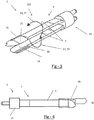
- FIG. 1 illustrates an example of an electrosurgical device 2 having a power connector 10 so that power can be transmitted through the electrosurgical device 2.
- the electrosurgical device 2 includes forceps 4 having a pair of working arms 6.
- the working arms 6 each include a tip 26 where power is transmitted through and/or gripping performed.
- the forceps 4 as illustrated have a skewing region 60 at a base proximate to the power connector 10.
- the skewing region 60 includes a skewing device 62 that skews the tips 26 of each working arm relative to each other in the directions 74.
- the skewing device 62 is moved along the electrosurgical device 2 in the direction 72 by a user pressing on the bias feature 68.
- the skewing device 62 As a force is applied to the bias feature 68 the skewing device 62 is moved along the skewing region 60 so that the skewing device 62 creates a force on the deflectors 70 forcing the deflector to deflect into the skewing device 62, which deflects the respective working arms 6 in the direction 74.
- a pathway 64 in the skewing device 62 travels along a pin 66 that guides the skewing device 62 so that the working arms 6 are moved between an askew position and a forceps position.
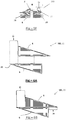
- FIG. 2 illustrates another example of an electrosurgical device 2 having a power connector 10 so that power can be transmitted through the electrosurgical device 2.
- the electrosurgical device 2 includes forceps 4 having a pair of working arms 6.
- the working arms 6 each include a tip 26 where power is transmitted through and/or gripping performed.
- the forceps 4 as illustrated having a skewing region 60 at a base proximate to the power connector 10.
- the skewing region 60 includes a skewing device 62 that skews the tips 26 of the working arms 6 in the directions 74.
- the skewing device 62 is moved along the electrosurgical device 2 in the direction 72 by a user pressing on the bias feature 68.
- the skewing device 62 moves along a pin 66 that is located within a pathway 64 that guides the skewing device 62.
- the pin 66 is moved into contact with a deflector 70 that deflects the working arms 6 in the directions 74 so that the working arms are moved from a forceps position to an askew position.
- the pathway 64 has a deflector 70 in the pathway 64 so that the deflector during movement of the skewing device 62 applies a force to the working arms 6 so that the working arms 6 are moved to an askew position.
- FIG 3 illustrates another example of an electrosurgical device 2.
- the electrosurgical device 2 includes forceps 4 including a pair of working arms 6 connected to a power connector 10.
- the working arms 6 include a contact surface 24, a body 27, and a tip 26.
- the working arms 6 are each rotatable in the direction 42 (i.e., an askew movement) from a bipolar configuration 102 to a monopolar configuration (the conversion of which is shown as an example in Figures 10A-10C ).
- FIG 4 illustrates a top view of the electrosurgical device 2 and forceps 4 of Figure 3 .
- the working arms 6 extend from the power connector 10.
- Each working arms 6 include a tip portion 26.
- the tips 26 of the working arms 6 are offset a distance (O) relative to each other.
- FIG. 5A illustrates a cross-sectional view of working arms 6 of an electrosurgical device (not shown) in a bipolar configuration 102 with the pair of working arms 6 being separated.
- the pair of working arms 6 are in a bipolar position 22 so that a contact surface 24 of each working arm 6 are directly opposing each other between line A and line B.
- a contact region 96 is formed between the working arms 6 and the working arms 6 are movable into contact so that the length of the respective contact surfaces 24 contact each other.
- Each of the working arms 6 include a tip 26 that forms an electrode edge that extends to a point and the tips 26 of the working arms face in opposing directions (although they may face in the same direction).
- the working arms 6 are made of a material with high thermal property 92 and the material with the high thermal property 92 is covered by a material with insulating thermal properties 90 that ends at the contact regions so that power may pass between the working arms 6 in the contact region 96.
- Figure 5B illustrates a cross-sectional view of the pair of working arms 6 moved into contact so that the ends 25 of the working arms align along line A and line B.
- the contact surfaces 24 are contiguous along the entire length.
- Figure 5C illustrates a cross-sectional view of a bipolar configuration 102 with the working arms 6 separated and skewed so that an offset (O) is present and the tips 26 extend beyond the body 27 of the opposing working arm 6.
- Figure 5D illustrates a cross-sectional view of the working arms 6 when the working arms 6 are moved to a monopolar position 20 when the electrosurgical device (not shown) is changed to a monopolar configuration 100.
- the working arms 6 are askew relative to each other and laterally offset a distance (O) so that the tips 26 extend beyond a body 27 of the opposing working arm 6 forming an edge electrode 54.
- Figure 5E illustrates tissue 200 located in the contact region 96 between the working arms 6 when the working arms 6 are moved from the position of Figure 5A towards the position of Figure 5B .
- power extends from one working arm 6 through the tissue 200 to the opposing working arm 6.
- Figure 5F illustrates the working arms 6 in the monopolar position 20 as shown in Figure 5D .
- the tips 26 form an edge electrode 54 and the edge electrode 54 is contacting tissue 200 so that power 12 is transferred from the tip to the tissue 200 for performing a predetermined procedure on the tissue 200.
- Figure 6A illustrates the working arms 6 in a bipolar configuration 102 where the working arms 6 even in a bipolar position 22 are always askew and laterally offset a distance (O) so that as the working arms are moved towards and away from each other a tip portion 26 protrudes out the distance (O).
- Figure 6B illustrates the working arms 6 in a monopolar configuration 100 where the working arms 6 are askew and laterally offset a distance (O).
- the working arms 6 in the monopolar position 20 maintain the same offset (O) as when the working arms are in the bipolar position 22 so that an edge electrode 54 extends beyond the opposing working arm 6.
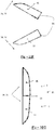
- Figures 7A-7D illustrates various configurations of the working arms 6.
- the tip 26 of Figures 7A-7C have an electrode edge that extends to sharp pointed tip 26 and Figure 7D has a blunt tip 26.
- the contact surface 24 of all four configurations are substantially flat so that when two working arms 6 towards each other the working surfaces 24 can be used as forceps (not shown).
- Each of the working arms 6 has a main body 27 connected to the tip 26.
- Each of the bodies 27 of Figure 7A-7D have a different shape.
- Figure 7A has a rectangular shape with rounded corners
- Figure 7B has an arcuate low profile
- Figure 7C is rectangular
- Figure 7D has a large bulbous portion.
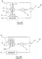
- Figures 8A and 8B illustrate the electrosurgical system 180 configured in the monopolar configuration 100 and the bipolar configuration 102 respectively.
- Figure 8A illustrates the working arms 6 in a monopolar position 20 so that the working arms 6 are offset and the tips 26 extend beyond the body 27 of the opposing working arms 6.
- Power 50 flows from the tip 26 to a ground pad 40.
- a switch 60 is moved electrically disconnecting one working arm 6 from being directly connected to the voltage source 52 and electrically connecting a ground pad 40 to the power source 52 so that a circuit is complete and power 50 flows between the ground pad 40 and the working arms 6.
- Figure 8B illustrates the working arms 6 in a bipolar position 22 so that the working arms 6 are separable relative to each other and the tips 26 of the working arms are aligned with the opposing working arm 6.
- Power 50 flows between the working arms 6 and any matter (not shown)in the contact region 96 between the working arms 6.
- a switch 60 is moved electrically disconnecting a ground pad 40 from being directly connected to the voltage source 52 and electrically connecting a the disconnected working arm 6 to the power source so that a circuit is complete and power 50 flows between the working arms 6.
- Figures 9A and 9B illustrate two possible configurations of the working arms 6 in the bipolar position 22.
- Figure 9A illustrates an axis 30 in the body 27 of the working arms between the tip 26 and the connection region 28.
- the working arms 6 are configured so that the contact surfaces 24 are aligned.
- Figure 9B illustrates an alternative configuration of the connection region 28 where the connection regions 28 include connection features 32 that lock when the working arms 6 are moved into a monopolar position (not shown).
- Figure 9C illustrates the working arms 6 of Figure 5B gripping tissue 200 that extends through the contact region 96.
- Figure 10A-10C illustrate an example of a sequence of reconfiguring the working arms 6 of Figure 9A from a bipolar position 22 ( Figure 10A ) to a monopolar position 20 ( Figure 10C ) so that the working arms 6 are rotationally offset.
- Figure 10A has the working arms 6 in a bipolar position 22 with each working arm having an axis 30.
- Figure 10B illustrates the working arms 6 rotating clockwise 34 (e.g., skewing direction 76) around the axis 30 so that the connection regions 28 are moved towards each other.
- Figure 10C shows the working arms 6 in a finally rotated around the axis 30 and in the monopolar position 20 with the connection regions 28 in contact with each other and the arms being askew so that the contact surfaces 24 have a rotational offset relative to each other.
- Figure 10D illustrates the working arms 6 in the monopolar position 20 and power 50 flowing between a tip 26 and tissue 200.
- Each body 27 has connection features 32 in the connection region 28 that are locked together in a monopolar position 20 with the contact surfaces 24 being rotationally offset (OR).
- Figure 10E-10G illustrate another example of a sequence of reconfiguring the working arms 6 from a bipolar position 22 ( Figure 10E ) to a monopolar position 20 ( Figure 10G ) so that the working arms 6 are rotationally offset.
- Figure 10E has the working arms 6 in a bipolar position 22 with each working arm having an axis 30.
- Figure 10F illustrates the working arms 6 rotating in opposing directions 34 (e.g., skewing direction 76) around the axis 30 so that the connection regions 28 are moved towards each other.
- Figure 10G shows the working arms 6 in a position finally rotated around the axis 30 and in the monopolar position 20 with the connection regions 28 in contact with each other and the working arms 6 being askew so that the contact surfaces 24 have a rotational offset relative to each other but located on the same side of the working arms 6.
- Figure 11A illustrates an example of a pair of working arms 6 that in a bipolar position 22 are located substantially across from each other with the ends substantially aligned so that the working arms are not askew and there is substantially no offset (O').
- the working arms 6 when in the bipolar position 22 move in a skewing direction 76 when used as forceps so that the working arms 6 are offset when in contact similar to when the working arms are in the monopolar position as is illustrated in Figure 11B .
- Figure 11B illustrates the pair of working arms 6 when the working arms 6 are in the monopolar position 20 and the working arms 6 are askew.
- the working arms 6 are moved so that the working arms 6 have a lateral offset (O).
- Figure 12A illustrates two different sized working arms 6 so that one working arm is a smaller working arm 6A and one working arm is a bigger working arm 6B.
- the working arms 6 in the bipolar position 22 as illustrated move directly towards and away from each other when used as forceps. However, the tip 26 of the bigger working arm 6B always extends beyond the smaller working arm 6A so that the working arms 6 are in an askew configuration relative to each other.
- Figure 12B illustrates the smaller working arm 6A and bigger working arm 6B in the monopolar position 20 so that the tip 26 of the bigger working arm 6B extends beyond the smaller working arm 6A at all times creating the working arms to be askew relative to each other.
- the tip 26 of the bigger working arm 6B extends a lateral offset distance (O) beyond the smaller working arm 6A.
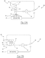
- Figures 13A and 13B illustrate the electrosurgical system 180 configured in the monopolar configuration 100 and the bipolar configuration 102 respectively.
- Figure 12A illustrates the working arms 6 in a monopolar position 20 so that the working arms 6 are each rotated about their axis 30 and the tips 26 are longitudinally aligned and the connection features 32 in the connection regions 28 are locked together.
- Power 50 flows from the tip 26 to a ground pad 40.
- a switch 60 is moved electrically disconnecting one working arm 6 from being directly connected to the voltage source 52 and electrically connecting a ground pad 40 to the power source so that a circuit is complete and power 50 flows between the ground pad 40 and the working arms 6.
- Figure 13B illustrates the working arms 6 in a bipolar position 22 so that the working arms 6 are separable relative to each other and the tips 26 and contact surfaces 24 of the working arms 6 are opposite and aligned with the opposing working arm 6.
- the connection regions 28 each include a connection feature 32 that is unlocked in the bipolar position 22.
- Power 50 flows between the working arms 6 and any matter (not shown) between the working arms 6.
- a switch 60 is moved electrically disconnecting a ground pad 40 from being directly connected to the voltage source 52 and electrically connecting a the disconnected working arm 6 to the power source so that a circuit is complete and power 50 flows between the working arms 6.
- any numerical values recited herein include all values from the lower value to the upper value in increments of one unit provided that there is a separation of at least 2 units between any lower value and any higher value.
- the amount of a component or a value of a process variable such as, for example, temperature, pressure, time and the like is, for example, from 1 to 90, preferably from 20 to 80, more preferably from 30 to 70, it is intended that values such as 15 to 85, 22 to 68, 43 to 51, 30 to 32 etc. are expressly enumerated in this specification.
- one unit is considered to be 0.0001, 0.001, 0.01 or 0.1 as appropriate.
Claims (14)
- Dispositif électrochirurgical (2) comprenant :un forceps (4) comportant :i. un premier bras de fonctionnement (6) ayant une surface de contact (24) etii. un second bras de fonctionnement (6) ayant une surface de contact (24) ;dans lequel le forceps (4) a une première configuration où la surface de contact (24) du premier bras de fonctionnement (6) et la surface de contact (24) du second bras de fonctionnement (6) sont opposées directement l'une à l'autre de sorte que les surfaces de contact des forceps (4) lorsqu'elles sont déplacées latéralement par rapport à un axe longitudinal du forceps puissent être utilisées pour saisir un article entre les bras de fonctionnement, et une pointe et la surface de contact du premier bras de fonctionnement sont alignées avec une pointe et la surface de contact du second bras de fonctionnement lorsque le premier bras de fonctionnement et le second bras de fonctionnement sont fermés ; etdans lequel le forceps a une seconde configuration où un premier bord de la surface de contact du premier bras de fonctionnement est de travers par rapport à un premier bord du second bras de fonctionnement lorsque le premier bras de fonctionnement et le second bras de fonctionnement sont fermés et la surface de contact du premier bras de fonctionnement est amenée en contact avec la surface de contact du second bras de fonctionnement.
- Dispositif électrochirurgical (2), selon la revendication 1
dans lequel dans la première configuration, les surfaces de contact du forceps (4) peuvent être utilisées pour saisir un article entre les bras de fonctionnement par une application de pression directe à des côtés opposés du forceps de sorte que le premier bras de fonctionnement et le second bras de fonctionnement se rapprochent et s'éloignent directement l'un de l'autre, et le forceps est configuré pour délivrer un premier courant de thérapie par l'intermédiaire du premier bras de fonctionnement, du second bras de fonctionnement, ou des deux ; et
dans lequel dans la seconde configuration, la surface de contact du premier bras de fonctionnement et la surface de contact du second bras de fonctionnement sont de travers l'une par rapport à l'autre et un bord d'électrode (54) est formé sur au moins un côté du forceps (4) de sorte qu'un second courant de thérapie parte du bord d'électrode (54). - Dispositif électrochirurgical selon l'une quelconque des revendications 1 à 2, dans lequel le forceps est un forceps électrochirurgical et la première configuration est une configuration bipolaire (102) et la seconde configuration est une configuration monopolaire (100).
- Dispositif électrochirurgical selon l'une quelconque des revendications 1 à 3, dans lequel le forceps est un forceps électrochirurgical et la première configuration est une configuration monopolaire (100) et la seconde configuration est une configuration monopolaire (100).
- Dispositif électrochirurgical selon l'une quelconque des revendications précédentes, dans lequel la surface de contact du premier bras de fonctionnement et la surface de contact du second bras de fonctionnement lorsqu'elles sont amenées en contact forment un bord d'électrode sur au moins un côté du forceps de sorte que le forceps soit configuré pour couper un tissu avec le bord d'électrode.
- Dispositif électrochirurgical selon la revendication 5, dans lequel le bord d'électrode est une lame mécanique.
- Dispositif électrochirurgical selon la revendication 5 ou la revendication 6, dans lequel le forceps est un forceps électrochirurgical et le bord d'électrode est une électrode monopolaire.
- Dispositif électrochirurgical selon l'une quelconque des revendications précédentes, dans lequel le forceps est un forceps électrochirurgical et le premier bras de fonctionnement (6) a un bord d'électrode (54) sur un premier côté et le second bras de fonctionnement (6) a un bord d'électrode (54) sur un second côté et le bord d'électrode du premier bras de fonctionnement et le bord d'électrode du second bras de fonctionnement s'étendent dans des directions opposées lorsque les forceps sont dans une configuration monopolaire, dans une configuration bipolaire, ou les deux et le bord d'électrode sur le premier bras de fonctionnement, le bord d'électrode sur le second bras de fonctionnement, ou les deux sont le bord d'électrode.
- Dispositif électrochirurgical selon l'une quelconque des revendications précédentes, dans lequel le forceps est un forceps électrochirurgical et le premier bras de fonctionnement et le second bras de fonctionnement sont de travers dans la première configuration, la seconde configuration, lorsqu'ils sont configurés sous forme de forceps, ou une position entre les deux.
- Dispositif électrochirurgical selon l'une quelconque des revendications précédentes, dans lequel le forceps est un forceps électrochirurgical et le premier bras de fonctionnement et le second bras de fonctionnement sont alignés dans la configuration bipolaire, lorsque le premier bras de fonctionnement et le second bras de fonctionnement sont séparés, ou les deux, et le premier bras de fonctionnement et le second bras de fonctionnement sont de travers lorsque le premier bras de fonctionnement et le second bras de fonctionnement sont dans la configuration monopolaire, sont en contact, ou les deux.
- Dispositif électrochirurgical selon l'une quelconque des revendications précédentes, dans lequel le forceps est un forceps électrochirurgical et les surfaces de contact (24) sont en contact l'une avec l'autre dans une configuration monopolaire.
- Dispositif électrochirurgical selon l'une quelconque des revendications précédentes, dans lequel le forceps est un forceps électrochirurgical et lorsque le premier bras de fonctionnement et le second bras de fonctionnement sont de travers dans une configuration monopolaire et un bord d'électrode sur le premier bras de fonctionnement est décalé et s'étend au-delà d'un corps du second bras de fonctionnement.
- Dispositif électrochirurgical selon l'une quelconque des revendications précédentes, dans lequel le forceps est un forceps électrochirurgical et un bord d'électrode (54) est la pointe (26) sur le premier bras de fonctionnement (6) et la pointe (26) sur le second bras de fonctionnement (6) et un courant de thérapie part du bord d'électrode sur le premier bras de fonctionnement, le bord d'électrode du second bras de fonctionnement, ou les deux individuellement ou simultanément.
- Dispositif électrochirurgical selon l'une quelconque des revendications précédentes, dans lequel le forceps est un forceps électrochirurgical et le bord d'électrode (54) est la pointe (26) du premier bras de fonctionnement ou du second bras de fonctionnement et la pointe (26) est contondante de sorte que la pointe ne puisse pas couper mécaniquement un tissu.
Applications Claiming Priority (3)
| Application Number | Priority Date | Filing Date | Title |
|---|---|---|---|
| US201361787731P | 2013-03-15 | 2013-03-15 | |
| US201361903500P | 2013-11-13 | 2013-11-13 | |
| PCT/US2014/015916 WO2014149250A1 (fr) | 2013-03-15 | 2014-02-12 | Pince de décalage |
Publications (2)
| Publication Number | Publication Date |
|---|---|
| EP2967718A1 EP2967718A1 (fr) | 2016-01-20 |
| EP2967718B1 true EP2967718B1 (fr) | 2017-04-05 |
Family
ID=50159598
Family Applications (3)
| Application Number | Title | Priority Date | Filing Date |
|---|---|---|---|
| EP17161375.5A Active EP3210560B1 (fr) | 2013-03-15 | 2014-02-12 | Pinces coudées |
| EP14706460.4A Not-in-force EP2967718B1 (fr) | 2013-03-15 | 2014-02-12 | Pince de décalage |
| EP14708170.7A Not-in-force EP2967720B1 (fr) | 2013-03-15 | 2014-02-12 | Pinces coudées |
Family Applications Before (1)
| Application Number | Title | Priority Date | Filing Date |
|---|---|---|---|
| EP17161375.5A Active EP3210560B1 (fr) | 2013-03-15 | 2014-02-12 | Pinces coudées |
Family Applications After (1)
| Application Number | Title | Priority Date | Filing Date |
|---|---|---|---|
| EP14708170.7A Not-in-force EP2967720B1 (fr) | 2013-03-15 | 2014-02-12 | Pinces coudées |
Country Status (5)
| Country | Link |
|---|---|
| US (4) | US10085793B2 (fr) |
| EP (3) | EP3210560B1 (fr) |
| JP (2) | JP6216031B2 (fr) |
| CN (3) | CN108078625B (fr) |
| WO (2) | WO2014143477A1 (fr) |
Cited By (1)
| Publication number | Priority date | Publication date | Assignee | Title |
|---|---|---|---|---|
| US11957401B2 (en) | 2019-04-16 | 2024-04-16 | Gyrus Acmi, Inc. | Electrosurgical instrument |
Families Citing this family (21)
| Publication number | Priority date | Publication date | Assignee | Title |
|---|---|---|---|---|
| DE102012012167A1 (de) * | 2012-06-19 | 2013-12-19 | Sutter Medizintechnik Gmbh | Koagulationszange mit einem Rohrschaft |
| CN105208955B (zh) | 2013-03-15 | 2018-11-06 | 捷锐士阿希迈公司(以奥林巴斯美国外科技术名义) | 组合式电外科设备 |
| EP2967719B1 (fr) | 2013-03-15 | 2017-07-12 | Gyrus Acmi Inc. | Instrument électrochirurgical |
| EP3210560B1 (fr) | 2013-03-15 | 2019-07-03 | Gyrus ACMI, Inc. (D.B.A. Olympus Surgical Technologies America) | Pinces coudées |
| WO2014150754A1 (fr) | 2013-03-15 | 2014-09-25 | GYRUS ACMI, INC. (d/b/a OLYMPUS SURGICAL TECHNOLOGIES AMERICA) | Dispositif électrochirurgical à combinaison |
| EP2974684B1 (fr) | 2013-03-15 | 2017-08-30 | Gyrus ACMI, Inc. | Dispositif électrochirurgical combiné |
| US20150112336A1 (en) * | 2013-10-20 | 2015-04-23 | Kogent Surgical, LLC | Bipolar forceps |
| US9918774B2 (en) | 2014-05-12 | 2018-03-20 | Gyrus Acmi, Inc. | Resistively heated electrosurgical device |
| US10045812B2 (en) * | 2014-08-11 | 2018-08-14 | Covidien Lp | Surgical instruments and methods for performing tonsillectomy and adenoidectomy procedures |
| US9974599B2 (en) * | 2014-08-15 | 2018-05-22 | Medtronic Ps Medical, Inc. | Multipurpose electrosurgical device |
| CN106659534B (zh) | 2014-08-20 | 2020-03-17 | 捷锐士阿希迈公司(以奥林巴斯美国外科技术名义) | 可重构电外科设备 |
| US9782216B2 (en) | 2015-03-23 | 2017-10-10 | Gyrus Acmi, Inc. | Medical forceps with vessel transection capability |
| WO2016169037A1 (fr) * | 2015-04-24 | 2016-10-27 | Covidien Lp | Dispositif d'obturation de vaisseaux à fonction de dissection fine |
| USD778442S1 (en) * | 2015-11-19 | 2017-02-07 | Bipad, Llc | Bipolar electrosurgery actuator system |
| CN113208725A (zh) | 2015-11-25 | 2021-08-06 | 捷锐士阿希迈公司(以奥林巴斯美国外科技术名义) | 执行器和电外科器械 |
| US10772676B2 (en) | 2016-05-31 | 2020-09-15 | Kogent Surgical, LLC | Microsurgical bipolar forceps |
| US11510698B2 (en) | 2016-07-06 | 2022-11-29 | Gyrus Acmi, Inc. | Multiple mode electrosurgical device |
| US11000328B2 (en) | 2016-11-09 | 2021-05-11 | Gyrus Acmi, Inc. | Resistively heated electrosurgical device |
| US11383373B2 (en) | 2017-11-02 | 2022-07-12 | Gyms Acmi, Inc. | Bias device for biasing a gripping device by biasing working arms apart |
| US10667834B2 (en) | 2017-11-02 | 2020-06-02 | Gyrus Acmi, Inc. | Bias device for biasing a gripping device with a shuttle on a central body |
| US11298801B2 (en) | 2017-11-02 | 2022-04-12 | Gyrus Acmi, Inc. | Bias device for biasing a gripping device including a central body and shuttles on the working arms |
Family Cites Families (329)
| Publication number | Priority date | Publication date | Assignee | Title |
|---|---|---|---|---|
| US1198958A (en) | 1915-07-12 | 1916-09-19 | Cleveland Dental Mfg Company | Tweezers. |
| US1530952A (en) | 1922-05-24 | 1925-03-24 | Charles L Lawton | Golf club |
| US2042985A (en) | 1934-08-22 | 1936-06-02 | Albert B Gardella | Tweezers |
| US2214984A (en) | 1938-04-07 | 1940-09-17 | Bachmann Henry | Tweezers |
| US2381084A (en) | 1943-07-15 | 1945-08-07 | Lillian Catherine Slad | Tweezers |
| US2575652A (en) | 1947-08-19 | 1951-11-20 | Ransom Y Bovee | Pocket tweezer article |
| US2894424A (en) | 1958-04-24 | 1959-07-14 | Jr Charles Swoope Vaughan | Tweezer type wire stripping tool having an adjustable stop and stop latching means |
| US3417752A (en) | 1965-11-12 | 1968-12-24 | Byron C. Butler | Magnetic clamp closing device for use with surgical instruments |
| US3399583A (en) | 1966-12-09 | 1968-09-03 | Hall Gordon Lance | Locking tweezers |
| US3465621A (en) | 1967-11-29 | 1969-09-09 | Ladd Res Ind | Locking tweezers |
| US3643663A (en) | 1968-10-16 | 1972-02-22 | F L Fischer | Coagulating instrument |
| US3576072A (en) | 1969-09-29 | 1971-04-27 | James Bernard Turner Foster | Surgical instrument |
| US3685518A (en) | 1970-07-29 | 1972-08-22 | Aesculap Werke Ag | Surgical instrument for high-frequency surgery |
| US3699632A (en) | 1971-07-30 | 1972-10-24 | Itt | Overriding latch mechanism |
| BE793463A (fr) | 1971-12-29 | 1973-06-28 | Ici Ltd | Instrument a enlever les agrafes |
| US3818784A (en) | 1973-01-03 | 1974-06-25 | Scient Components Inc | Changeable tip tweezers and the like |
| US3913586A (en) | 1974-01-28 | 1975-10-21 | Gomco Surgical Mfg Co | Hemostat |
| US4041952A (en) | 1976-03-04 | 1977-08-16 | Valleylab, Inc. | Electrosurgical forceps |
| US4171700A (en) | 1976-10-13 | 1979-10-23 | Erbe Elektromedizin Gmbh & Co. Kg | High-frequency surgical apparatus |
| DE2717607C3 (de) | 1977-04-20 | 1981-06-25 | Coloplast A/S, Espergaerde | Magnetverschlußstopfen für einen Darmausgang |
| US4202337A (en) | 1977-06-14 | 1980-05-13 | Concept, Inc. | Bipolar electrosurgical knife |
| US4418692A (en) | 1978-11-17 | 1983-12-06 | Guay Jean Louis | Device for treating living tissue with an electric current |
| US4318313A (en) | 1980-03-10 | 1982-03-09 | Tartaglia John A | Tweezer forceps |
| CA1192465A (fr) | 1981-03-11 | 1985-08-27 | Edward A. Lottick | Electrocautere a commutateur amovible |
| US4375218A (en) | 1981-05-26 | 1983-03-01 | Digeronimo Ernest M | Forceps, scalpel and blood coagulating surgical instrument |
| US4407069A (en) | 1981-12-08 | 1983-10-04 | The Scott & Fetzer Company | Scissors with cushioned stop |
| US4463759A (en) | 1982-01-13 | 1984-08-07 | Garito Jon C | Universal finger/foot switch adaptor for tube-type electrosurgical instrument |
| US4443935A (en) | 1982-03-01 | 1984-04-24 | Trident Surgical Corporation | Process for making electrosurgical scalpel pencil |
| US4494543A (en) | 1982-03-05 | 1985-01-22 | Hart Ernest D | Instrument for extracting splinters |
| US4504707A (en) | 1982-03-15 | 1985-03-12 | Kyushu Hitachi Maxell, Ltd. | Push-button switch locking device for use in electric appliance |
| JPS58193907U (ja) | 1982-06-18 | 1983-12-23 | 持田製薬株式会社 | 電気メスを付設する超音波メス |
| US4492231A (en) | 1982-09-17 | 1985-01-08 | Auth David C | Non-sticking electrocautery system and forceps |
| US4492832A (en) | 1982-12-23 | 1985-01-08 | Neomed, Incorporated | Hand-controllable switching device for electrosurgical instruments |
| US4524648A (en) | 1984-08-17 | 1985-06-25 | Chung Charng J | Fixation tweezers |
| US4655215A (en) | 1985-03-15 | 1987-04-07 | Harold Pike | Hand control for electrosurgical electrodes |
| US4757612A (en) | 1985-03-21 | 1988-07-19 | Preposreve S.A.R.L. | Fixed-blade knife with retractable blade cover |
| US4669470A (en) | 1985-11-20 | 1987-06-02 | Brandfield Robert T | Surgical forceps/scissors |
| US4686980A (en) | 1986-04-17 | 1987-08-18 | Alcon Laboratories, Inc. | Disposable bipolar instrument |
| US4688569A (en) | 1986-06-09 | 1987-08-25 | Medi-Tech, Inc. | Finger actuated surgical electrode holder |
| EP0430929B1 (fr) | 1986-07-17 | 1994-06-01 | Erbe Elektromedizin GmbH | Appareil chirurgical à haute fréquence pour la coagulation thermique de tissus biologiques |
| US4713885A (en) | 1986-12-08 | 1987-12-22 | Ronald Keklak | Safe utility knife |
| US4784136A (en) | 1987-01-12 | 1988-11-15 | Peter Klein | Electrical epilation |
| DE3722142A1 (de) | 1987-06-17 | 1989-01-05 | S & T Spingler Tritt Chirurgis | Federzange oder pinzette, insbesondere koagulationspinzette |
| US5035695A (en) | 1987-11-30 | 1991-07-30 | Jaroy Weber, Jr. | Extendable electrocautery surgery apparatus and method |
| US4896661A (en) | 1988-02-05 | 1990-01-30 | Pfizer, Inc. | Multi purpose orthopedic ratcheting forceps |
| US5071426A (en) | 1989-04-06 | 1991-12-10 | Stuart Dolgin | Surgical scalpel with retractable blade guard |
| CA2014302A1 (fr) | 1989-04-14 | 1990-10-14 | John A. Santangelo | Mecanisme de verrouillage a plusieurs positions pour pince-forceps |
| US5104397A (en) | 1989-04-14 | 1992-04-14 | Codman & Shurtleff, Inc. | Multi-position latching mechanism for forceps |
| US4935027A (en) | 1989-08-21 | 1990-06-19 | Inbae Yoon | Surgical suture instrument with remotely controllable suture material advancement |
| US5021616A (en) | 1989-11-03 | 1991-06-04 | Compaq Computer Corporation | Switch cover |
| US6099550A (en) * | 1989-12-05 | 2000-08-08 | Yoon; Inbae | Surgical instrument having jaws and an operating channel and method for use thereof |
| US5922001A (en) | 1989-12-05 | 1999-07-13 | Yoon; Inbae | Surgical instrument with jaws and a movable internal blade member and method for use thereof |
| US5293878A (en) | 1991-04-04 | 1994-03-15 | Symbiosis Corporation | Endoscopic surgical instruments having stepped rotatable end effectors |
| US5190541A (en) | 1990-10-17 | 1993-03-02 | Boston Scientific Corporation | Surgical instrument and method |
| US5226904A (en) | 1991-02-08 | 1993-07-13 | Conmed Corporation | Electrosurgical instrument |
| US5147378A (en) | 1991-03-05 | 1992-09-15 | Harold Markham | Grapsing forceps |
| US5176702A (en) | 1991-04-04 | 1993-01-05 | Symbiosis Corporation | Ratchet locking mechanism for surgical instruments |
| US5208983A (en) | 1991-08-19 | 1993-05-11 | Masse Joseph H | Retracting cutter |
| US5196009A (en) | 1991-09-11 | 1993-03-23 | Kirwan Jr Lawrence T | Non-sticking electrosurgical device having nickel tips |
| CA2075319C (fr) | 1991-09-26 | 1998-06-30 | Ernie Aranyi | Manche pour instruments chirurgicaux |
| US5207691A (en) | 1991-11-01 | 1993-05-04 | Medical Scientific, Inc. | Electrosurgical clip applicator |
| US5531744A (en) | 1991-11-01 | 1996-07-02 | Medical Scientific, Inc. | Alternative current pathways for bipolar surgical cutting tool |
| US5197964A (en) | 1991-11-12 | 1993-03-30 | Everest Medical Corporation | Bipolar instrument utilizing one stationary electrode and one movable electrode |
| US6355032B1 (en) | 1995-06-07 | 2002-03-12 | Arthrocare Corporation | Systems and methods for selective electrosurgical treatment of body structures |
| US6974453B2 (en) | 1993-05-10 | 2005-12-13 | Arthrocare Corporation | Dual mode electrosurgical clamping probe and related methods |
| US5484435A (en) | 1992-01-15 | 1996-01-16 | Conmed Corporation | Bipolar electrosurgical instrument for use in minimally invasive internal surgical procedures |
| US5281216A (en) | 1992-03-31 | 1994-01-25 | Valleylab, Inc. | Electrosurgical bipolar treating apparatus |
| US5314424A (en) | 1992-04-06 | 1994-05-24 | United States Surgical Corporation | Surgical instrument locking mechanism |
| US5370659A (en) | 1992-04-09 | 1994-12-06 | Olympus Optical Co., Ltd. | Grasping forceps for medical treatment |
| US5318589A (en) | 1992-04-15 | 1994-06-07 | Microsurge, Inc. | Surgical instrument for endoscopic surgery |
| US5207696A (en) | 1992-04-30 | 1993-05-04 | Medical Sterile Products, Inc. | Surgical scalpel |
| US5443463A (en) | 1992-05-01 | 1995-08-22 | Vesta Medical, Inc. | Coagulating forceps |
| US5293863A (en) | 1992-05-08 | 1994-03-15 | Loma Linda University Medical Center | Bladed endoscopic retractor |
| US5402734A (en) | 1992-12-11 | 1995-04-04 | Melles Griot, Inc. | Optical table having debris retention structures |
| US5403312A (en) | 1993-07-22 | 1995-04-04 | Ethicon, Inc. | Electrosurgical hemostatic device |
| US5807393A (en) | 1992-12-22 | 1998-09-15 | Ethicon Endo-Surgery, Inc. | Surgical tissue treating device with locking mechanism |
| US5342359A (en) | 1993-02-05 | 1994-08-30 | Everest Medical Corporation | Bipolar coagulation device |
| US5440813A (en) | 1993-06-04 | 1995-08-15 | Roskam; Scott H. | Rideless scissors with an adjustable load transverse to the pivot axis on a pivot joint |
| US5709680A (en) | 1993-07-22 | 1998-01-20 | Ethicon Endo-Surgery, Inc. | Electrosurgical hemostatic device |
| DE4496959T1 (de) | 1993-09-14 | 1996-09-26 | Microsurge Inc | Endoskopisches chirurgisches Instrument mit geführten Klemmbacken bzw. Backen und Sperrsteuerung |
| US5456695A (en) | 1993-10-25 | 1995-10-10 | United States Surgical Corporation | Multi-tool surgical apparatus |
| US5458598A (en) | 1993-12-02 | 1995-10-17 | Cabot Technology Corporation | Cutting and coagulating forceps |
| US5441498A (en) | 1994-02-16 | 1995-08-15 | Envision Surgical Systems, Inc. | Method of using a multimodality probe with extendable bipolar electrodes |
| US5626577A (en) | 1994-02-28 | 1997-05-06 | Harris; George A. | Manually extendable electrocautery surgical apparatus |
| US5472442A (en) | 1994-03-23 | 1995-12-05 | Valleylab Inc. | Moveable switchable electrosurgical handpiece |
| US5413575A (en) | 1994-04-19 | 1995-05-09 | Innovative Medical Technologies, Ltd. | Multifunction electrocautery tool |
| DE69429543T2 (de) | 1994-08-24 | 2002-08-22 | Vesta Medical Inc | Koagulationszange |
| US5562503A (en) | 1994-12-05 | 1996-10-08 | Ellman; Alan G. | Bipolar adaptor for electrosurgical instrument |
| US6447511B1 (en) | 1994-12-13 | 2002-09-10 | Symbiosis Corporation | Bipolar endoscopic surgical scissor blades and instrument incorporating the same |
| US5540685A (en) | 1995-01-06 | 1996-07-30 | Everest Medical Corporation | Bipolar electrical scissors with metal cutting edges and shearing surfaces |
| US5573424A (en) | 1995-02-09 | 1996-11-12 | Everest Medical Corporation | Apparatus for interfacing a bipolar electrosurgical instrument to a monopolar generator |
| US5779701A (en) | 1995-04-27 | 1998-07-14 | Symbiosis Corporation | Bipolar endoscopic surgical scissor blades and instrument incorporating the same |
| JPH08322847A (ja) | 1995-05-31 | 1996-12-10 | Kyocera Corp | 血管凝固止血装置 |
| US6837887B2 (en) | 1995-06-07 | 2005-01-04 | Arthrocare Corporation | Articulated electrosurgical probe and methods |
| GB9526627D0 (en) | 1995-12-29 | 1996-02-28 | Gyrus Medical Ltd | An electrosurgical instrument and an electrosurgical electrode assembly |
| US5693052A (en) | 1995-09-01 | 1997-12-02 | Megadyne Medical Products, Inc. | Coated bipolar electrocautery |
| US5674220A (en) | 1995-09-29 | 1997-10-07 | Ethicon Endo-Surgery, Inc. | Bipolar electrosurgical clamping device |
| US6428538B1 (en) | 1995-10-20 | 2002-08-06 | United States Surgical Corporation | Apparatus and method for thermal treatment of body tissue |
| GB9521772D0 (en) | 1995-10-24 | 1996-01-03 | Gyrus Medical Ltd | An electrosurgical instrument |
| JPH09122140A (ja) | 1995-10-31 | 1997-05-13 | Olympus Optical Co Ltd | 手術装置 |
| US5658281A (en) | 1995-12-04 | 1997-08-19 | Valleylab Inc | Bipolar electrosurgical scissors and method of manufacture |
| US5827281A (en) | 1996-01-05 | 1998-10-27 | Levin; John M. | Insulated surgical scissors |
| US5810805A (en) * | 1996-02-09 | 1998-09-22 | Conmed Corporation | Bipolar surgical devices and surgical methods |
| US5702390A (en) | 1996-03-12 | 1997-12-30 | Ethicon Endo-Surgery, Inc. | Bioplar cutting and coagulation instrument |
| US6325795B1 (en) | 1996-03-12 | 2001-12-04 | Sherwood Services Ag | Replaceable accessory cord and handswitch |
| DE19628482A1 (de) | 1996-07-15 | 1998-01-22 | Berchtold Gmbh & Co Geb | Verfahren zum Betrieb eines Hochfrequenz-Chirurgiegerätes und Hochfrequenz-Chirurgiegerät |
| DE19730724A1 (de) | 1996-07-18 | 1998-01-29 | Valleylab Inc | Elektrochirurgische Instrumente und Verfahren zu ihrer Herstellung |
| US7112199B2 (en) | 1996-09-20 | 2006-09-26 | Ioan Cosmescu | Multifunctional telescopic monopolar/bipolar surgical device and method therefore |
| US5735849A (en) | 1996-11-07 | 1998-04-07 | Everest Medical Corporation | Endoscopic forceps with thumb-slide lock release mechanism |
| JPH10137259A (ja) | 1996-11-08 | 1998-05-26 | Olympus Optical Co Ltd | 電気手術装置 |
| US5891142A (en) | 1996-12-06 | 1999-04-06 | Eggers & Associates, Inc. | Electrosurgical forceps |
| US5891140A (en) | 1996-12-23 | 1999-04-06 | Cardiothoracic Systems, Inc. | Electrosurgical device for harvesting a vessel especially the internal mammary artery for coronary artery bypass grafting |
| US6113596A (en) | 1996-12-30 | 2000-09-05 | Enable Medical Corporation | Combination monopolar-bipolar electrosurgical instrument system, instrument and cable |
| US7083613B2 (en) | 1997-03-05 | 2006-08-01 | The Trustees Of Columbia University In The City Of New York | Ringed forceps |
| US5884954A (en) | 1997-06-04 | 1999-03-23 | Trozera; Thomas | Locking tweezers for tying fly-fishing hooks |
| US6402747B1 (en) | 1997-07-21 | 2002-06-11 | Sherwood Services Ag | Handswitch cord and circuit |
| US6102909A (en) | 1997-08-26 | 2000-08-15 | Ethicon, Inc. | Scissorlike electrosurgical cutting instrument |
| US6726686B2 (en) | 1997-11-12 | 2004-04-27 | Sherwood Services Ag | Bipolar electrosurgical instrument for sealing vessels |
| US6050996A (en) | 1997-11-12 | 2000-04-18 | Sherwood Services Ag | Bipolar electrosurgical instrument with replaceable electrodes |
| US6486419B2 (en) | 1998-01-09 | 2002-11-26 | Ricoh Company, Ltd. | Multifunctional image forming apparatus having a covered main power switch |
| JP3610306B2 (ja) | 2000-07-05 | 2005-01-12 | オリンパス株式会社 | 高周波処置具 |
| US6273887B1 (en) | 1998-01-23 | 2001-08-14 | Olympus Optical Co., Ltd. | High-frequency treatment tool |
| JP3384750B2 (ja) | 1998-09-02 | 2003-03-10 | オリンパス光学工業株式会社 | 高周波処置具 |
| US5902301A (en) | 1998-02-23 | 1999-05-11 | Everest Medical Corporation | Cutting/coagulating forceps with interleaved electrodes |
| US6540695B1 (en) | 1998-04-08 | 2003-04-01 | Senorx, Inc. | Biopsy anchor device with cutter |
| US6514252B2 (en) | 1998-05-01 | 2003-02-04 | Perfect Surgical Techniques, Inc. | Bipolar surgical instruments having focused electrical fields |
| US6030384A (en) | 1998-05-01 | 2000-02-29 | Nezhat; Camran | Bipolar surgical instruments having focused electrical fields |
| WO1999066850A1 (fr) | 1998-06-22 | 1999-12-29 | Lina Medical Aps | Dispositif d'electrochirugie pour coaguler et pratiquer des incisions, procede de sectionnement de vaisseaux sanguins, et procede de coagulation et d'incision de tissus ou de sectionnement de tissus |
| US6679882B1 (en) | 1998-06-22 | 2004-01-20 | Lina Medical Aps | Electrosurgical device for coagulating and for making incisions, a method of severing blood vessels and a method of coagulating and for making incisions in or severing tissue |
| US6117169A (en) | 1998-06-24 | 2000-09-12 | Sulzer Carbomedics Inc. | Living hinge attachment of leaflet to a valve body |
| JP4225624B2 (ja) | 1998-08-27 | 2009-02-18 | オリンパス株式会社 | 高周波処置装置 |
| US6585735B1 (en) | 1998-10-23 | 2003-07-01 | Sherwood Services Ag | Endoscopic bipolar electrosurgical forceps |
| ES2251260T3 (es) | 1998-10-23 | 2006-04-16 | Sherwood Services Ag | Forceps de obturacion de vasos abiertos con miembro de tope. |
| WO2000030524A2 (fr) * | 1998-11-24 | 2000-06-02 | Inbae Yoon | Instrument chirurgical a terminal desaxe monte rotatif et son procede d'utilisation |
| US6053908A (en) | 1999-01-07 | 2000-04-25 | Design Standards Corporation | Ratchet assembly for surgical instrument |
| US6174309B1 (en) | 1999-02-11 | 2001-01-16 | Medical Scientific, Inc. | Seal & cut electrosurgical instrument |
| US6110171A (en) | 1999-03-09 | 2000-08-29 | Everest Medical Corporation | Electrosurgical cutting and coagulating instrument for open surgery |
| US6190386B1 (en) | 1999-03-09 | 2001-02-20 | Everest Medical Corporation | Electrosurgical forceps with needle electrodes |
| US6152923A (en) | 1999-04-28 | 2000-11-28 | Sherwood Services Ag | Multi-contact forceps and method of sealing, coagulating, cauterizing and/or cutting vessels and tissue |
| US6117158A (en) | 1999-07-07 | 2000-09-12 | Ethicon Endo-Surgery, Inc. | Ratchet release mechanism for hand held instruments |
| GB9919722D0 (en) | 1999-08-20 | 1999-10-20 | Surgical Innovations Ltd | Laparoscopic forceps handle |
| US6464698B1 (en) | 1999-12-02 | 2002-10-15 | C.R. Bard, Inc. | Medical device having an incrementally displaceable electrode |
| JP2001170070A (ja) | 1999-12-20 | 2001-06-26 | Olympus Optical Co Ltd | 医療用処置具 |
| US6358268B1 (en) | 2000-03-06 | 2002-03-19 | Robert B. Hunt | Surgical instrument |
| US6558385B1 (en) | 2000-09-22 | 2003-05-06 | Tissuelink Medical, Inc. | Fluid-assisted medical device |
| US8048070B2 (en) | 2000-03-06 | 2011-11-01 | Salient Surgical Technologies, Inc. | Fluid-assisted medical devices, systems and methods |
| US6953461B2 (en) | 2002-05-16 | 2005-10-11 | Tissuelink Medical, Inc. | Fluid-assisted medical devices, systems and methods |
| US6905498B2 (en) | 2000-04-27 | 2005-06-14 | Atricure Inc. | Transmural ablation device with EKG sensor and pacing electrode |
| US6494886B1 (en) | 2000-06-22 | 2002-12-17 | Granit Medical Innovation, Inc. | Off-set clamp mechanism and associated method for minimally invasive surgery |
| JP2002022007A (ja) | 2000-07-04 | 2002-01-23 | Kanzaki Kokyukoki Mfg Co Ltd | 車軸駆動装置 |
| US6827717B2 (en) | 2000-08-26 | 2004-12-07 | Olympus Winter & Ibe Gmbh | Monopolar and bipolar electrode for a urological resectoscope |
| US7387628B1 (en) | 2000-09-15 | 2008-06-17 | Boston Scientific Scimed, Inc. | Methods and systems for focused bipolar tissue ablation |
| US6656177B2 (en) | 2000-10-23 | 2003-12-02 | Csaba Truckai | Electrosurgical systems and techniques for sealing tissue |
| US8133218B2 (en) | 2000-12-28 | 2012-03-13 | Senorx, Inc. | Electrosurgical medical system and method |
| US6840938B1 (en) | 2000-12-29 | 2005-01-11 | Intuitive Surgical, Inc. | Bipolar cauterizing instrument |
| US6458128B1 (en) | 2001-01-24 | 2002-10-01 | Ethicon, Inc. | Electrosurgical instrument with a longitudinal element for conducting RF energy and moving a cutting element |
| US20020107517A1 (en) | 2001-01-26 | 2002-08-08 | Witt David A. | Electrosurgical instrument for coagulation and cutting |
| US20020106609A1 (en) | 2001-02-06 | 2002-08-08 | Palermo Rosanne M. | Dental forceps |
| DE60121229T2 (de) | 2001-04-06 | 2007-05-24 | Sherwood Services Ag | Vorrichtung zum abdichten und teilen eines gefässes mit nichtleitendem endanschlag |
| US6551313B1 (en) | 2001-05-02 | 2003-04-22 | John M. Levin | Electrosurgical instrument with separate cutting and coagulating members |
| JP3722729B2 (ja) | 2001-06-04 | 2005-11-30 | オリンパス株式会社 | 内視鏡用処置装置 |
| US6513206B1 (en) | 2001-07-20 | 2003-02-04 | International Business Machines Corporation | Retaining clip for panel mounted input/output connector |
| US6808525B2 (en) | 2001-08-27 | 2004-10-26 | Gyrus Medical, Inc. | Bipolar electrosurgical hook probe for cutting and coagulating tissue |
| US6652514B2 (en) | 2001-09-13 | 2003-11-25 | Alan G. Ellman | Intelligent selection system for electrosurgical instrument |
| US6773434B2 (en) | 2001-09-18 | 2004-08-10 | Ethicon, Inc. | Combination bipolar forceps and scissors instrument |
| US6926716B2 (en) | 2001-11-09 | 2005-08-09 | Surgrx Inc. | Electrosurgical instrument |
| US6752183B2 (en) | 2001-12-07 | 2004-06-22 | Nalge Nunc International Corporation | Waste funnel system |
| US7052496B2 (en) | 2001-12-11 | 2006-05-30 | Olympus Optical Co., Ltd. | Instrument for high-frequency treatment and method of high-frequency treatment |
| US6942662B2 (en) | 2001-12-27 | 2005-09-13 | Gyrus Group Plc | Surgical Instrument |
| US6726690B2 (en) | 2002-01-17 | 2004-04-27 | Concept Matrix, Llc | Diskectomy instrument and method |
| US7699849B2 (en) | 2002-01-17 | 2010-04-20 | Concept Matrix, Llc | Diskectomy instrument with disposable blade head |
| JP2003210483A (ja) | 2002-01-21 | 2003-07-29 | Koichi Hosokawa | 高周波組織切開具 |
| US20030181904A1 (en) | 2002-01-23 | 2003-09-25 | Levine Andy H. | Electrosurgical cutting, coagulating and suction instrument |
| US6749609B1 (en) | 2002-02-05 | 2004-06-15 | Origin Medsystems, Inc. | Electrocautery scissors |
| US6623499B1 (en) | 2002-02-21 | 2003-09-23 | Michael Andreini | Retractable safety scalpel |
| US6648839B2 (en) | 2002-02-28 | 2003-11-18 | Misonix, Incorporated | Ultrasonic medical treatment device for RF cauterization and related method |
| US6752767B2 (en) | 2002-04-16 | 2004-06-22 | Vivant Medical, Inc. | Localization element with energized tip |
| US20040030330A1 (en) | 2002-04-18 | 2004-02-12 | Brassell James L. | Electrosurgery systems |
| US6749610B2 (en) | 2002-08-15 | 2004-06-15 | Kirwan Surgical Products, Inc. | Electro-surgical forceps having fully plated tines and process for manufacturing same |
| US7276068B2 (en) | 2002-10-04 | 2007-10-02 | Sherwood Services Ag | Vessel sealing instrument with electrical cutting mechanism |
| US7931649B2 (en) | 2002-10-04 | 2011-04-26 | Tyco Healthcare Group Lp | Vessel sealing instrument with electrical cutting mechanism |
| US7041096B2 (en) | 2002-10-24 | 2006-05-09 | Synergetics Usa, Inc. | Electrosurgical generator apparatus |
| JP2004147724A (ja) | 2002-10-29 | 2004-05-27 | Aisin Kiko Co Ltd | 使い捨て用手術機器及びその再使用防止方法 |
| EP1415600A1 (fr) | 2002-11-04 | 2004-05-06 | Stryker Trauma - Selzach AG | Pince orthopédique avec crémaillère de blocage |
| US7244257B2 (en) | 2002-11-05 | 2007-07-17 | Sherwood Services Ag | Electrosurgical pencil having a single button variable control |
| US7108694B2 (en) | 2002-11-08 | 2006-09-19 | Olympus Corporation | Heat-emitting treatment device |
| US20040097912A1 (en) | 2002-11-18 | 2004-05-20 | Gonnering Wayne J. | Electrosurgical generator and method with removable front panel having replaceable electrical connection sockets and illuminated receptacles |
| US6835082B2 (en) | 2002-11-18 | 2004-12-28 | Conmed Corporation | Monopolar electrosurgical multi-plug connector device and method which accepts multiple different connector plugs |
| US6905499B1 (en) | 2002-11-26 | 2005-06-14 | Thermal Corp. | Heat pipe for cautery surgical Instrument |
| US6860882B2 (en) | 2003-02-06 | 2005-03-01 | Codman & Shurtleff, Inc. | Electro-surgical bipolar forceps |
| WO2004080278A2 (fr) | 2003-03-06 | 2004-09-23 | Tissuelink Medical, Inc. | Procedes, systemes et dispositifs medicaux assistes d'un fluide |
| US7753909B2 (en) | 2003-05-01 | 2010-07-13 | Covidien Ag | Electrosurgical instrument which reduces thermal damage to adjacent tissue |
| US7156846B2 (en) | 2003-06-13 | 2007-01-02 | Sherwood Services Ag | Vessel sealer and divider for use with small trocars and cannulas |
| US7150749B2 (en) | 2003-06-13 | 2006-12-19 | Sherwood Services Ag | Vessel sealer and divider having elongated knife stroke and safety cutting mechanism |
| US7563261B2 (en) | 2003-08-11 | 2009-07-21 | Electromedical Associates Llc | Electrosurgical device with floating-potential electrodes |
| US7367976B2 (en) | 2003-11-17 | 2008-05-06 | Sherwood Services Ag | Bipolar forceps having monopolar extension |
| US7232440B2 (en) | 2003-11-17 | 2007-06-19 | Sherwood Services Ag | Bipolar forceps having monopolar extension |
| US7131970B2 (en) | 2003-11-19 | 2006-11-07 | Sherwood Services Ag | Open vessel sealing instrument with cutting mechanism |
| US7252667B2 (en) | 2003-11-19 | 2007-08-07 | Sherwood Services Ag | Open vessel sealing instrument with cutting mechanism and distal lockout |
| US7503917B2 (en) | 2003-11-20 | 2009-03-17 | Covidien Ag | Electrosurgical pencil with improved controls |
| US7156842B2 (en) | 2003-11-20 | 2007-01-02 | Sherwood Services Ag | Electrosurgical pencil with improved controls |
| GB2408936B (en) | 2003-12-09 | 2007-07-18 | Gyrus Group Plc | A surgical instrument |
| US7632269B2 (en) | 2004-01-16 | 2009-12-15 | Ethicon Endo-Surgery, Inc. | Electrosurgical instrument with replaceable cartridge |
| US7094231B1 (en) | 2004-01-22 | 2006-08-22 | Ellman Alan G | Dual-mode electrosurgical instrument |
| US7223267B2 (en) | 2004-02-06 | 2007-05-29 | Misonix, Incorporated | Ultrasonic probe with detachable slidable cauterization forceps |
| US7955331B2 (en) | 2004-03-12 | 2011-06-07 | Ethicon Endo-Surgery, Inc. | Electrosurgical instrument and method of use |
| JP4643328B2 (ja) | 2004-04-07 | 2011-03-02 | オリンパス株式会社 | 医療用結紮縫合装置 |
| US20050283149A1 (en) | 2004-06-08 | 2005-12-22 | Thorne Jonathan O | Electrosurgical cutting instrument |
| DE202004010780U1 (de) | 2004-07-02 | 2004-09-09 | Karl Storz Gmbh & Co. Kg | Medizinisches Instrument für die Elektrochirurgie |
| US7896875B2 (en) | 2004-07-20 | 2011-03-01 | Microline Surgical, Inc. | Battery powered electrosurgical system |
| US20060190035A1 (en) | 2004-10-08 | 2006-08-24 | Sherwood Services Ag | Latching mechanism for forceps |
| US20060084973A1 (en) * | 2004-10-14 | 2006-04-20 | Dylan Hushka | Momentary rocker switch for use with vessel sealing instruments |
| US7686827B2 (en) | 2004-10-21 | 2010-03-30 | Covidien Ag | Magnetic closure mechanism for hemostat |
| US7686804B2 (en) | 2005-01-14 | 2010-03-30 | Covidien Ag | Vessel sealer and divider with rotating sealer and cutter |
| US7670336B2 (en) | 2005-03-25 | 2010-03-02 | Boston Scientific Scimed, Inc. | Ablation probe with heat sink |
| US7674261B2 (en) | 2005-03-28 | 2010-03-09 | Elliquence, Llc | Electrosurgical instrument with enhanced capability |
| US8287535B2 (en) | 2005-05-11 | 2012-10-16 | Mayo Foundation For Medical Education And Research | Apparatus and methods for internal surgical procedures |
| US7727177B2 (en) | 2005-06-21 | 2010-06-01 | Inasurgica, Llc | Four function surgical instrument |
| US7618413B2 (en) | 2005-06-22 | 2009-11-17 | Boston Scientific Scimed, Inc. | Medical device control system |
| US20070016105A1 (en) | 2005-06-27 | 2007-01-18 | Mamourian Alexander C | Wire torque apparatus, wire insertion devices, improved aneurysm clips and improved aneurysm clip applicators |
| US7749221B2 (en) | 2005-08-23 | 2010-07-06 | Rontal Daniel A | Retractable electrosurgical electrode |
| US7879035B2 (en) | 2005-09-30 | 2011-02-01 | Covidien Ag | Insulating boot for electrosurgical forceps |
| US7789878B2 (en) | 2005-09-30 | 2010-09-07 | Covidien Ag | In-line vessel sealer and divider |
| US7722607B2 (en) | 2005-09-30 | 2010-05-25 | Covidien Ag | In-line vessel sealer and divider |
| EP1769765B1 (fr) | 2005-09-30 | 2012-03-21 | Covidien AG | Manchon isolant pour pince électrochirurgicale |
| US8702691B2 (en) | 2005-10-19 | 2014-04-22 | Thermage, Inc. | Treatment apparatus and methods for delivering energy at multiple selectable depths in tissue |
| CA2626540A1 (fr) | 2005-10-26 | 2007-05-03 | Brigham And Women's Hospital, Inc. | Dispositifs et methodes pour traiter une regurgitation de la valvule mitrale |
| US7513896B2 (en) | 2006-01-24 | 2009-04-07 | Covidien Ag | Dual synchro-resonant electrosurgical apparatus with bi-directional magnetic coupling |
| US20070179491A1 (en) | 2006-01-31 | 2007-08-02 | Medtronic, Inc. | Sensing needle for ablation therapy |
| AU2006338507A1 (en) | 2006-02-15 | 2007-08-23 | Daniel Bohler | Rotary power tool |
| US7942872B2 (en) | 2006-02-27 | 2011-05-17 | Moshe Ein-Gal | Blended monopolar and bipolar application of RF energy |
| DE102006027150A1 (de) * | 2006-06-08 | 2007-12-13 | Celon Ag Medical Instruments | Vorrichtung zum Schneiden und Koagulieren von Gewebe |
| US8251989B1 (en) | 2006-06-13 | 2012-08-28 | Encision, Inc. | Combined bipolar and monopolar electrosurgical instrument and method |
| US7717914B2 (en) | 2006-07-11 | 2010-05-18 | Olympus Medical Systems Corporation | Treatment device |
| US7419490B2 (en) | 2006-07-27 | 2008-09-02 | Applied Medical Resources Corporation | Bipolar electrosurgical scissors |
| US20080033428A1 (en) | 2006-08-04 | 2008-02-07 | Sherwood Services Ag | System and method for disabling handswitching on an electrosurgical instrument |
| US8177784B2 (en) | 2006-09-27 | 2012-05-15 | Electromedical Associates, Llc | Electrosurgical device having floating potential electrode and adapted for use with a resectoscope |
| US20080147092A1 (en) | 2006-10-23 | 2008-06-19 | Michael Rogge | Hybrid energy instrument combined with clip application capability |
| US7758577B2 (en) | 2006-12-05 | 2010-07-20 | Ethicon Endo-Surgery, Inc. | Monopolar resection device and method of use |
| US20080154300A1 (en) | 2006-12-15 | 2008-06-26 | Noel Jabbour | Surgical forceps |
| US20080236860A1 (en) | 2007-04-02 | 2008-10-02 | Prevention Products, Inc. | Electrical switch cover |
| US20080249523A1 (en) | 2007-04-03 | 2008-10-09 | Tyco Healthcare Group Lp | Controller for flexible tissue ablation procedures |
| US8267935B2 (en) | 2007-04-04 | 2012-09-18 | Tyco Healthcare Group Lp | Electrosurgical instrument reducing current densities at an insulator conductor junction |
| US7931668B2 (en) | 2007-04-26 | 2011-04-26 | Sloat Glenn B | Medical tool with retractible heads |
| GB0708783D0 (en) | 2007-05-04 | 2007-06-13 | Gyrus Medical Ltd | Electrosurgical system |
| US8931682B2 (en) | 2007-06-04 | 2015-01-13 | Ethicon Endo-Surgery, Inc. | Robotically-controlled shaft based rotary drive systems for surgical instruments |
| US9155526B2 (en) | 2007-08-29 | 2015-10-13 | Olympus Corporation | Puncture apparatus with automatic puncture function |
| US8998891B2 (en) | 2007-08-30 | 2015-04-07 | Ellman International, Inc. | Tri-frequency electrosurgical instrument |
| US8568410B2 (en) | 2007-08-31 | 2013-10-29 | Ethicon Endo-Surgery, Inc. | Electrical ablation surgical instruments |
| US8262655B2 (en) | 2007-11-21 | 2012-09-11 | Ethicon Endo-Surgery, Inc. | Bipolar forceps |
| DE102007047243A1 (de) | 2007-09-25 | 2009-04-02 | Karl Storz Gmbh & Co. Kg | Bipolares medizinisches Instrument |
| GB0719733D0 (en) | 2007-10-09 | 2007-11-21 | Gyrus Medical Ltd | Electrosurgical system |
| US9050098B2 (en) | 2007-11-28 | 2015-06-09 | Covidien Ag | Cordless medical cauterization and cutting device |
| US8338726B2 (en) | 2009-08-26 | 2012-12-25 | Covidien Ag | Two-stage switch for cordless hand-held ultrasonic cautery cutting device |
| DE102007061483A1 (de) | 2007-12-20 | 2009-07-02 | Erbe Elektromedizin Gmbh | Chirurgiegerätesteckersystem |
| US8882756B2 (en) | 2007-12-28 | 2014-11-11 | Medtronic Advanced Energy Llc | Fluid-assisted electrosurgical devices, methods and systems |
| US20090171147A1 (en) | 2007-12-31 | 2009-07-02 | Woojin Lee | Surgical instrument |
| GB2456353A (en) | 2008-01-14 | 2009-07-15 | Gyrus Medical Ltd | Electrosurgical system including a switch adapter cable |
| JP2009182479A (ja) | 2008-01-29 | 2009-08-13 | Duaxes Corp | フィルタリング装置 |
| US8870867B2 (en) | 2008-02-06 | 2014-10-28 | Aesculap Ag | Articulable electrosurgical instrument with a stabilizable articulation actuator |
| EP2359762B1 (fr) | 2008-03-31 | 2013-03-06 | Applied Medical Resources Corporation | Système électrochirurgical configurable de façon sélective pour la coupe ou pour la coagulation |
| US9642669B2 (en) | 2008-04-01 | 2017-05-09 | Olympus Corporation | Treatment system, and treatment method for living tissue using energy |
| JP5380705B2 (ja) | 2008-05-15 | 2014-01-08 | 株式会社リバーセイコー | 内視鏡用高周波止血鉗子 |
| GB0809461D0 (en) | 2008-05-23 | 2008-07-02 | Gyrus Medical Ltd | An electrosurgical generator and system |
| US8298226B2 (en) | 2008-05-23 | 2012-10-30 | Gyrus Medical Limited | Electrosurgical generator and system |
| US8361065B2 (en) | 2008-07-10 | 2013-01-29 | HS West Investements, LLC | Electrosurgical instrument with an ablation mode and a coagulation mode |
| US9028491B2 (en) | 2008-08-18 | 2015-05-12 | Alan G. Ellman | MIS electrosurgical handpiece |
| CN102149338B (zh) | 2008-09-12 | 2015-07-22 | 伊西康内外科公司 | 指尖控制的超声装置 |
| FR2937430B1 (fr) | 2008-10-16 | 2010-12-31 | Commissariat Energie Atomique | Pince brucelles a elements de prehension montes a pivotement sur des branches. |
| US8287534B2 (en) | 2008-12-09 | 2012-10-16 | Carl Balog | Light emitting electrosurgical scalpel |
| US8632539B2 (en) * | 2009-01-14 | 2014-01-21 | Covidien Lp | Vessel sealer and divider |
| US8485413B2 (en) | 2009-02-05 | 2013-07-16 | Ethicon Endo-Surgery, Inc. | Surgical stapling instrument comprising an articulation joint |
| FR2942128B1 (fr) | 2009-02-19 | 2011-02-11 | Moria Sa | Pince chirurgicale |
| EP2398416B1 (fr) | 2009-02-23 | 2015-10-28 | Medtronic Advanced Energy LLC | Dispositif électrochirurgical assisté par un fluide |
| WO2010101897A1 (fr) | 2009-03-02 | 2010-09-10 | Bovie Medical Corporation | Appareil chirurgical pour fermeture de tissu et découpe |
| US8418073B2 (en) | 2009-03-09 | 2013-04-09 | Intuitive Surgical Operations, Inc. | User interfaces for electrosurgical tools in robotic surgical systems |
| DE102009011912A1 (de) | 2009-03-10 | 2010-09-16 | Celon Ag Medical Instruments | Hochfrequenz-Chirurgiegerät |
| WO2010109908A1 (fr) | 2009-03-27 | 2010-09-30 | 国立大学法人 滋賀医科大学 | Dispositif de traitement médical |
| US8657851B2 (en) | 2009-05-21 | 2014-02-25 | Moria Sa | Surgical tweezers |
| US8319134B2 (en) | 2009-06-19 | 2012-11-27 | E Surgical, Llc | Electrosurgical pencil switch, circuitry, and method of assembly |
| US8328170B2 (en) | 2009-06-19 | 2012-12-11 | Toyota Motor Engineering & Manufacturing North America , Inc. | Clamping apparatus |
| GB2472216A (en) | 2009-07-28 | 2011-02-02 | Gyrus Medical Ltd | Bipolar electrosurgical instrument with four electrodes |
| DE102009049401B4 (de) | 2009-08-20 | 2023-09-28 | Erbe Elektromedizin Gmbh | Elektrochirurgische Zange |
| US8287536B2 (en) | 2009-08-26 | 2012-10-16 | Tyco Healthcare Group Lp | Cutting assembly for surgical instruments |
| US20110054462A1 (en) | 2009-08-28 | 2011-03-03 | Ellman Alan G | Electrosurgical instrument with multi-function handpiece |
| US9820806B2 (en) | 2009-09-29 | 2017-11-21 | Covidien Lp | Switch assembly for electrosurgical instrument |
| US20110098733A1 (en) | 2009-10-26 | 2011-04-28 | Ky Huynh | Medical device assembly having freedom of rotation |
| US20110112530A1 (en) | 2009-11-06 | 2011-05-12 | Keller Craig A | Battery Powered Electrosurgery |
| EP2523620B1 (fr) | 2010-01-15 | 2019-06-19 | Medtronic Advanced Energy LLC | Dispositif électrochirurgical |
| US9592090B2 (en) | 2010-03-11 | 2017-03-14 | Medtronic Advanced Energy Llc | Bipolar electrosurgical cutter with position insensitive return electrode contact |
| EP2471472B1 (fr) | 2010-03-11 | 2014-10-29 | Olympus Medical Systems Corp. | Forceps pour assister des opérations intrapéritonéales et techniques d'utilisation associées |
| US8496682B2 (en) | 2010-04-12 | 2013-07-30 | Ethicon Endo-Surgery, Inc. | Electrosurgical cutting and sealing instruments with cam-actuated jaws |
| US8491626B2 (en) | 2010-06-02 | 2013-07-23 | Covidien Lp | Apparatus for performing an electrosurgical procedure |
| US9011437B2 (en) | 2010-07-23 | 2015-04-21 | Ethicon Endo-Surgery, Inc. | Electrosurgical cutting and sealing instrument |
| ES2912092T3 (es) | 2010-10-01 | 2022-05-24 | Applied Med Resources | Instrumentos electroquirúrgicos y conexiones a los mismos |
| US9655672B2 (en) * | 2010-10-04 | 2017-05-23 | Covidien Lp | Vessel sealing instrument |
| US8906018B2 (en) | 2010-10-18 | 2014-12-09 | Covidien Lp | Surgical forceps |
| CN103200892B (zh) | 2010-10-20 | 2015-08-26 | 泰尔茂心血管系统公司 | 外科用处理器具 |
| US8628529B2 (en) | 2010-10-26 | 2014-01-14 | Ethicon Endo-Surgery, Inc. | Surgical instrument with magnetic clamping force |
| JP2012093563A (ja) | 2010-10-27 | 2012-05-17 | Nitto Denko Corp | タッチパネル用光導波路の製法 |
| WO2012061535A2 (fr) | 2010-11-02 | 2012-05-10 | U.S. Patent Innovations | Système et procédé pour coupe électrochirurgicale au gaz conducteur pour améliorer le soin des escarres, sceller de manière étanche des vaisseaux et des tissus |
| US9144453B2 (en) | 2010-11-08 | 2015-09-29 | Bovie Medical Corporation | Multi-mode electrosurgical apparatus |
| US8998899B2 (en) | 2010-11-08 | 2015-04-07 | Bovie Medical Corporation | Multi-button electrosurgical apparatus |
| US8945122B2 (en) | 2010-11-16 | 2015-02-03 | Covidien Lp | Power glove |
| CN102476360B (zh) | 2010-11-24 | 2013-10-16 | 佛山普立华科技有限公司 | 夹具 |
| US20120150165A1 (en) | 2010-12-10 | 2012-06-14 | Salient Surgical Technologies, Inc. | Bipolar Electrosurgical Device |
| EP2486885B1 (fr) | 2011-02-09 | 2013-05-01 | Erbe Elektromedizin GmbH | Fiche femelle universelle |
| US9427281B2 (en) | 2011-03-11 | 2016-08-30 | Medtronic Advanced Energy Llc | Bronchoscope-compatible catheter provided with electrosurgical device |
| US8900161B2 (en) | 2011-04-01 | 2014-12-02 | Cook Medical Technologies Llc | Tissue sampling device and method |
| US8939972B2 (en) | 2011-05-06 | 2015-01-27 | Covidien Lp | Surgical forceps |
| US9358065B2 (en) | 2011-06-23 | 2016-06-07 | Covidien Lp | Shaped electrode bipolar resection apparatus, system and methods of use |
| US9636167B2 (en) | 2011-05-31 | 2017-05-02 | Covidien Lp | Surgical device with DC power connection |
| US9788882B2 (en) | 2011-09-08 | 2017-10-17 | Arthrocare Corporation | Plasma bipolar forceps |
| US8961515B2 (en) | 2011-09-28 | 2015-02-24 | Covidien Lp | Electrosurgical instrument |
| GB2496624A (en) | 2011-11-16 | 2013-05-22 | Gyrus Medical Ltd | Surgical instrument with a plurality of handswitches |
| US9023035B2 (en) | 2012-01-06 | 2015-05-05 | Covidien Lp | Monopolar pencil with integrated bipolar/ligasure tweezers |
| US9204879B2 (en) | 2012-06-28 | 2015-12-08 | Ethicon Endo-Surgery, Inc. | Flexible drive member |
| US9439665B2 (en) | 2012-12-20 | 2016-09-13 | Covidien Lp | Pediatric combination surgical device |
| GB2509110B (en) | 2012-12-20 | 2018-07-18 | Gerard Michael Brooke | Electrosurgical Forceps with Adjustable Spring |
| EP2974684B1 (fr) | 2013-03-15 | 2017-08-30 | Gyrus ACMI, Inc. | Dispositif électrochirurgical combiné |
| EP3210560B1 (fr) | 2013-03-15 | 2019-07-03 | Gyrus ACMI, Inc. (D.B.A. Olympus Surgical Technologies America) | Pinces coudées |
| WO2014150754A1 (fr) | 2013-03-15 | 2014-09-25 | GYRUS ACMI, INC. (d/b/a OLYMPUS SURGICAL TECHNOLOGIES AMERICA) | Dispositif électrochirurgical à combinaison |
| BR122015018777A2 (pt) | 2013-03-15 | 2019-08-27 | Gyrus Acmi Inc Tambem Comercializando Como Olympus Surgical Tech America | aparelho eletrocirúrgico |
| EP2967719B1 (fr) | 2013-03-15 | 2017-07-12 | Gyrus Acmi Inc. | Instrument électrochirurgical |
| CN105208955B (zh) | 2013-03-15 | 2018-11-06 | 捷锐士阿希迈公司(以奥林巴斯美国外科技术名义) | 组合式电外科设备 |
| US9717548B2 (en) | 2013-09-24 | 2017-08-01 | Covidien Lp | Electrode for use in a bipolar electrosurgical instrument |
| US9918774B2 (en) | 2014-05-12 | 2018-03-20 | Gyrus Acmi, Inc. | Resistively heated electrosurgical device |
| CN106659534B (zh) | 2014-08-20 | 2020-03-17 | 捷锐士阿希迈公司(以奥林巴斯美国外科技术名义) | 可重构电外科设备 |
| US11547467B2 (en) | 2016-01-11 | 2023-01-10 | Gyrus Acmi, Inc. | Advanced energy device with bipolar dissection capability |
-
2014
- 2014-02-12 EP EP17161375.5A patent/EP3210560B1/fr active Active
- 2014-02-12 JP JP2016500239A patent/JP6216031B2/ja active Active
- 2014-02-12 CN CN201810113314.0A patent/CN108078625B/zh not_active Expired - Fee Related
- 2014-02-12 EP EP14706460.4A patent/EP2967718B1/fr not_active Not-in-force
- 2014-02-12 JP JP2016500243A patent/JP6129400B2/ja not_active Expired - Fee Related
- 2014-02-12 EP EP14708170.7A patent/EP2967720B1/fr not_active Not-in-force
- 2014-02-12 CN CN201480015016.8A patent/CN105142556B/zh not_active Expired - Fee Related
- 2014-02-12 CN CN201480027040.3A patent/CN105246425B/zh not_active Expired - Fee Related
- 2014-02-12 US US14/178,577 patent/US10085793B2/en active Active
- 2014-02-12 WO PCT/US2014/015948 patent/WO2014143477A1/fr active Application Filing
- 2014-02-12 US US14/178,569 patent/US9901389B2/en active Active
- 2014-02-12 WO PCT/US2014/015916 patent/WO2014149250A1/fr active Application Filing
-
2018
- 2018-07-30 US US16/048,553 patent/US11744634B2/en active Active
-
2023
- 2023-07-25 US US18/358,448 patent/US20240058051A1/en active Pending
Non-Patent Citations (1)
| Title |
|---|
| None * |
Cited By (1)
| Publication number | Priority date | Publication date | Assignee | Title |
|---|---|---|---|---|
| US11957401B2 (en) | 2019-04-16 | 2024-04-16 | Gyrus Acmi, Inc. | Electrosurgical instrument |
Also Published As
| Publication number | Publication date |
|---|---|
| JP2016510636A (ja) | 2016-04-11 |
| CN105142556B (zh) | 2019-01-08 |
| CN105246425A (zh) | 2016-01-13 |
| US9901389B2 (en) | 2018-02-27 |
| US20180333196A1 (en) | 2018-11-22 |
| CN105246425B (zh) | 2018-03-09 |
| CN108078625B (zh) | 2020-11-17 |
| EP2967720B1 (fr) | 2017-05-31 |
| WO2014149250A1 (fr) | 2014-09-25 |
| JP6216031B2 (ja) | 2017-10-18 |
| JP6129400B2 (ja) | 2017-05-17 |
| EP3210560B1 (fr) | 2019-07-03 |
| US10085793B2 (en) | 2018-10-02 |
| US20240058051A1 (en) | 2024-02-22 |
| EP2967720A1 (fr) | 2016-01-20 |
| WO2014143477A1 (fr) | 2014-09-18 |
| EP2967718A1 (fr) | 2016-01-20 |
| CN108078625A (zh) | 2018-05-29 |
| JP2016510634A (ja) | 2016-04-11 |
| US20140276786A1 (en) | 2014-09-18 |
| EP3210560A1 (fr) | 2017-08-30 |
| CN105142556A (zh) | 2015-12-09 |
| US11744634B2 (en) | 2023-09-05 |
| US20140276804A1 (en) | 2014-09-18 |
Similar Documents
| Publication | Publication Date | Title |
|---|---|---|
| US20240058051A1 (en) | Offset forceps | |
| US11779384B2 (en) | Combination electrosurgical device | |
| US11224477B2 (en) | Combination electrosurgical device | |
| EP3052041A1 (fr) | Dispositif électrochirurgical combiné multimode |
Legal Events
| Date | Code | Title | Description |
|---|---|---|---|
| PUAI | Public reference made under article 153(3) epc to a published international application that has entered the european phase |
Free format text: ORIGINAL CODE: 0009012 |
|
| 17P | Request for examination filed |
Effective date: 20150909 |
|
| AK | Designated contracting states |
Kind code of ref document: A1 Designated state(s): AL AT BE BG CH CY CZ DE DK EE ES FI FR GB GR HR HU IE IS IT LI LT LU LV MC MK MT NL NO PL PT RO RS SE SI SK SM TR |
|
| AX | Request for extension of the european patent |
Extension state: BA ME |
|
| 17Q | First examination report despatched |
Effective date: 20160419 |
|
| DAX | Request for extension of the european patent (deleted) | ||
| GRAP | Despatch of communication of intention to grant a patent |
Free format text: ORIGINAL CODE: EPIDOSNIGR1 |
|
| INTG | Intention to grant announced |
Effective date: 20161209 |
|
| GRAS | Grant fee paid |
Free format text: ORIGINAL CODE: EPIDOSNIGR3 |
|
| GRAA | (expected) grant |
Free format text: ORIGINAL CODE: 0009210 |
|
| AK | Designated contracting states |
Kind code of ref document: B1 Designated state(s): AL AT BE BG CH CY CZ DE DK EE ES FI FR GB GR HR HU IE IS IT LI LT LU LV MC MK MT NL NO PL PT RO RS SE SI SK SM TR |
|
| REG | Reference to a national code |
Ref country code: GB Ref legal event code: FG4D |
|
| REG | Reference to a national code |
Ref country code: CH Ref legal event code: EP |
|
| REG | Reference to a national code |
Ref country code: AT Ref legal event code: REF Ref document number: 881051 Country of ref document: AT Kind code of ref document: T Effective date: 20170415 |
|
| REG | Reference to a national code |
Ref country code: IE Ref legal event code: FG4D |
|
| REG | Reference to a national code |
Ref country code: DE Ref legal event code: R096 Ref document number: 602014008310 Country of ref document: DE |
|
| REG | Reference to a national code |
Ref country code: NL Ref legal event code: MP Effective date: 20170405 |
|
| REG | Reference to a national code |
Ref country code: LT Ref legal event code: MG4D |
|
| REG | Reference to a national code |
Ref country code: AT Ref legal event code: MK05 Ref document number: 881051 Country of ref document: AT Kind code of ref document: T Effective date: 20170405 |
|
| PG25 | Lapsed in a contracting state [announced via postgrant information from national office to epo] |
Ref country code: NL Free format text: LAPSE BECAUSE OF FAILURE TO SUBMIT A TRANSLATION OF THE DESCRIPTION OR TO PAY THE FEE WITHIN THE PRESCRIBED TIME-LIMIT Effective date: 20170405 |
|
| PG25 | Lapsed in a contracting state [announced via postgrant information from national office to epo] |
Ref country code: GR Free format text: LAPSE BECAUSE OF FAILURE TO SUBMIT A TRANSLATION OF THE DESCRIPTION OR TO PAY THE FEE WITHIN THE PRESCRIBED TIME-LIMIT Effective date: 20170706 Ref country code: ES Free format text: LAPSE BECAUSE OF FAILURE TO SUBMIT A TRANSLATION OF THE DESCRIPTION OR TO PAY THE FEE WITHIN THE PRESCRIBED TIME-LIMIT Effective date: 20170405 Ref country code: AT Free format text: LAPSE BECAUSE OF FAILURE TO SUBMIT A TRANSLATION OF THE DESCRIPTION OR TO PAY THE FEE WITHIN THE PRESCRIBED TIME-LIMIT Effective date: 20170405 Ref country code: HR Free format text: LAPSE BECAUSE OF FAILURE TO SUBMIT A TRANSLATION OF THE DESCRIPTION OR TO PAY THE FEE WITHIN THE PRESCRIBED TIME-LIMIT Effective date: 20170405 Ref country code: NO Free format text: LAPSE BECAUSE OF FAILURE TO SUBMIT A TRANSLATION OF THE DESCRIPTION OR TO PAY THE FEE WITHIN THE PRESCRIBED TIME-LIMIT Effective date: 20170705 Ref country code: FI Free format text: LAPSE BECAUSE OF FAILURE TO SUBMIT A TRANSLATION OF THE DESCRIPTION OR TO PAY THE FEE WITHIN THE PRESCRIBED TIME-LIMIT Effective date: 20170405 Ref country code: LT Free format text: LAPSE BECAUSE OF FAILURE TO SUBMIT A TRANSLATION OF THE DESCRIPTION OR TO PAY THE FEE WITHIN THE PRESCRIBED TIME-LIMIT Effective date: 20170405 |
|
| PG25 | Lapsed in a contracting state [announced via postgrant information from national office to epo] |
Ref country code: PL Free format text: LAPSE BECAUSE OF FAILURE TO SUBMIT A TRANSLATION OF THE DESCRIPTION OR TO PAY THE FEE WITHIN THE PRESCRIBED TIME-LIMIT Effective date: 20170405 Ref country code: LV Free format text: LAPSE BECAUSE OF FAILURE TO SUBMIT A TRANSLATION OF THE DESCRIPTION OR TO PAY THE FEE WITHIN THE PRESCRIBED TIME-LIMIT Effective date: 20170405 Ref country code: SE Free format text: LAPSE BECAUSE OF FAILURE TO SUBMIT A TRANSLATION OF THE DESCRIPTION OR TO PAY THE FEE WITHIN THE PRESCRIBED TIME-LIMIT Effective date: 20170405 Ref country code: RS Free format text: LAPSE BECAUSE OF FAILURE TO SUBMIT A TRANSLATION OF THE DESCRIPTION OR TO PAY THE FEE WITHIN THE PRESCRIBED TIME-LIMIT Effective date: 20170405 Ref country code: IS Free format text: LAPSE BECAUSE OF FAILURE TO SUBMIT A TRANSLATION OF THE DESCRIPTION OR TO PAY THE FEE WITHIN THE PRESCRIBED TIME-LIMIT Effective date: 20170805 Ref country code: BG Free format text: LAPSE BECAUSE OF FAILURE TO SUBMIT A TRANSLATION OF THE DESCRIPTION OR TO PAY THE FEE WITHIN THE PRESCRIBED TIME-LIMIT Effective date: 20170705 |
|
| REG | Reference to a national code |
Ref country code: DE Ref legal event code: R097 Ref document number: 602014008310 Country of ref document: DE |
|
| PG25 | Lapsed in a contracting state [announced via postgrant information from national office to epo] |
Ref country code: RO Free format text: LAPSE BECAUSE OF FAILURE TO SUBMIT A TRANSLATION OF THE DESCRIPTION OR TO PAY THE FEE WITHIN THE PRESCRIBED TIME-LIMIT Effective date: 20170405 Ref country code: DK Free format text: LAPSE BECAUSE OF FAILURE TO SUBMIT A TRANSLATION OF THE DESCRIPTION OR TO PAY THE FEE WITHIN THE PRESCRIBED TIME-LIMIT Effective date: 20170405 Ref country code: CZ Free format text: LAPSE BECAUSE OF FAILURE TO SUBMIT A TRANSLATION OF THE DESCRIPTION OR TO PAY THE FEE WITHIN THE PRESCRIBED TIME-LIMIT Effective date: 20170405 Ref country code: SK Free format text: LAPSE BECAUSE OF FAILURE TO SUBMIT A TRANSLATION OF THE DESCRIPTION OR TO PAY THE FEE WITHIN THE PRESCRIBED TIME-LIMIT Effective date: 20170405 Ref country code: EE Free format text: LAPSE BECAUSE OF FAILURE TO SUBMIT A TRANSLATION OF THE DESCRIPTION OR TO PAY THE FEE WITHIN THE PRESCRIBED TIME-LIMIT Effective date: 20170405 |
|
| PLBE | No opposition filed within time limit |
Free format text: ORIGINAL CODE: 0009261 |
|
| STAA | Information on the status of an ep patent application or granted ep patent |
Free format text: STATUS: NO OPPOSITION FILED WITHIN TIME LIMIT |
|
| PG25 | Lapsed in a contracting state [announced via postgrant information from national office to epo] |
Ref country code: SM Free format text: LAPSE BECAUSE OF FAILURE TO SUBMIT A TRANSLATION OF THE DESCRIPTION OR TO PAY THE FEE WITHIN THE PRESCRIBED TIME-LIMIT Effective date: 20170405 Ref country code: IT Free format text: LAPSE BECAUSE OF FAILURE TO SUBMIT A TRANSLATION OF THE DESCRIPTION OR TO PAY THE FEE WITHIN THE PRESCRIBED TIME-LIMIT Effective date: 20170405 |
|
| 26N | No opposition filed |
Effective date: 20180108 |
|
| PG25 | Lapsed in a contracting state [announced via postgrant information from national office to epo] |
Ref country code: SI Free format text: LAPSE BECAUSE OF FAILURE TO SUBMIT A TRANSLATION OF THE DESCRIPTION OR TO PAY THE FEE WITHIN THE PRESCRIBED TIME-LIMIT Effective date: 20170405 |
|
| REG | Reference to a national code |
Ref country code: CH Ref legal event code: PL |
|
| PG25 | Lapsed in a contracting state [announced via postgrant information from national office to epo] |
Ref country code: MC Free format text: LAPSE BECAUSE OF FAILURE TO SUBMIT A TRANSLATION OF THE DESCRIPTION OR TO PAY THE FEE WITHIN THE PRESCRIBED TIME-LIMIT Effective date: 20170405 |
|
| REG | Reference to a national code |
Ref country code: IE Ref legal event code: MM4A |
|
| REG | Reference to a national code |
Ref country code: BE Ref legal event code: MM Effective date: 20180228 |
|
| PG25 | Lapsed in a contracting state [announced via postgrant information from national office to epo] |
Ref country code: CH Free format text: LAPSE BECAUSE OF NON-PAYMENT OF DUE FEES Effective date: 20180228 Ref country code: LI Free format text: LAPSE BECAUSE OF NON-PAYMENT OF DUE FEES Effective date: 20180228 Ref country code: LU Free format text: LAPSE BECAUSE OF NON-PAYMENT OF DUE FEES Effective date: 20180212 |
|
| REG | Reference to a national code |
Ref country code: FR Ref legal event code: ST Effective date: 20181031 |
|
| PG25 | Lapsed in a contracting state [announced via postgrant information from national office to epo] |
Ref country code: IE Free format text: LAPSE BECAUSE OF NON-PAYMENT OF DUE FEES Effective date: 20180212 |
|
| PG25 | Lapsed in a contracting state [announced via postgrant information from national office to epo] |
Ref country code: FR Free format text: LAPSE BECAUSE OF NON-PAYMENT OF DUE FEES Effective date: 20180228 Ref country code: BE Free format text: LAPSE BECAUSE OF NON-PAYMENT OF DUE FEES Effective date: 20180228 |
|
| PG25 | Lapsed in a contracting state [announced via postgrant information from national office to epo] |
Ref country code: MT Free format text: LAPSE BECAUSE OF NON-PAYMENT OF DUE FEES Effective date: 20180212 |
|
| PG25 | Lapsed in a contracting state [announced via postgrant information from national office to epo] |
Ref country code: TR Free format text: LAPSE BECAUSE OF FAILURE TO SUBMIT A TRANSLATION OF THE DESCRIPTION OR TO PAY THE FEE WITHIN THE PRESCRIBED TIME-LIMIT Effective date: 20170405 |
|
| PG25 | Lapsed in a contracting state [announced via postgrant information from national office to epo] |
Ref country code: PT Free format text: LAPSE BECAUSE OF FAILURE TO SUBMIT A TRANSLATION OF THE DESCRIPTION OR TO PAY THE FEE WITHIN THE PRESCRIBED TIME-LIMIT Effective date: 20170405 |
|
| PG25 | Lapsed in a contracting state [announced via postgrant information from national office to epo] |
Ref country code: HU Free format text: LAPSE BECAUSE OF FAILURE TO SUBMIT A TRANSLATION OF THE DESCRIPTION OR TO PAY THE FEE WITHIN THE PRESCRIBED TIME-LIMIT; INVALID AB INITIO Effective date: 20140212 Ref country code: CY Free format text: LAPSE BECAUSE OF FAILURE TO SUBMIT A TRANSLATION OF THE DESCRIPTION OR TO PAY THE FEE WITHIN THE PRESCRIBED TIME-LIMIT Effective date: 20170405 Ref country code: MK Free format text: LAPSE BECAUSE OF NON-PAYMENT OF DUE FEES Effective date: 20170405 |
|
| PG25 | Lapsed in a contracting state [announced via postgrant information from national office to epo] |
Ref country code: AL Free format text: LAPSE BECAUSE OF FAILURE TO SUBMIT A TRANSLATION OF THE DESCRIPTION OR TO PAY THE FEE WITHIN THE PRESCRIBED TIME-LIMIT Effective date: 20170405 |
|
| PGFP | Annual fee paid to national office [announced via postgrant information from national office to epo] |
Ref country code: GB Payment date: 20210225 Year of fee payment: 8 Ref country code: DE Payment date: 20210225 Year of fee payment: 8 |
|
| REG | Reference to a national code |
Ref country code: DE Ref legal event code: R119 Ref document number: 602014008310 Country of ref document: DE |
|
| GBPC | Gb: european patent ceased through non-payment of renewal fee |
Effective date: 20220212 |
|
| PG25 | Lapsed in a contracting state [announced via postgrant information from national office to epo] |
Ref country code: GB Free format text: LAPSE BECAUSE OF NON-PAYMENT OF DUE FEES Effective date: 20220212 Ref country code: DE Free format text: LAPSE BECAUSE OF NON-PAYMENT OF DUE FEES Effective date: 20220901 |