EP2966236A1 - Verbindungsvorrichtung für Stahlbeton-Fertigtsäulen mit trockener Fuge - Google Patents
Verbindungsvorrichtung für Stahlbeton-Fertigtsäulen mit trockener Fuge Download PDFInfo
- Publication number
- EP2966236A1 EP2966236A1 EP14382261.7A EP14382261A EP2966236A1 EP 2966236 A1 EP2966236 A1 EP 2966236A1 EP 14382261 A EP14382261 A EP 14382261A EP 2966236 A1 EP2966236 A1 EP 2966236A1
- Authority
- EP
- European Patent Office
- Prior art keywords
- joining device
- cover
- holes
- webs
- rebars
- Prior art date
- Legal status (The legal status is an assumption and is not a legal conclusion. Google has not performed a legal analysis and makes no representation as to the accuracy of the status listed.)
- Withdrawn
Links
Images


Classifications
-
- E—FIXED CONSTRUCTIONS
- E04—BUILDING
- E04B—GENERAL BUILDING CONSTRUCTIONS; WALLS, e.g. PARTITIONS; ROOFS; FLOORS; CEILINGS; INSULATION OR OTHER PROTECTION OF BUILDINGS
- E04B1/00—Constructions in general; Structures which are not restricted either to walls, e.g. partitions, or floors or ceilings or roofs
- E04B1/18—Structures comprising elongated load-supporting parts, e.g. columns, girders, skeletons
- E04B1/20—Structures comprising elongated load-supporting parts, e.g. columns, girders, skeletons the supporting parts consisting of concrete, e.g. reinforced concrete, or other stonelike material
- E04B1/21—Connections specially adapted therefor
- E04B1/215—Connections specially adapted therefor comprising metallic plates or parts
-
- E—FIXED CONSTRUCTIONS
- E04—BUILDING
- E04B—GENERAL BUILDING CONSTRUCTIONS; WALLS, e.g. PARTITIONS; ROOFS; FLOORS; CEILINGS; INSULATION OR OTHER PROTECTION OF BUILDINGS
- E04B1/00—Constructions in general; Structures which are not restricted either to walls, e.g. partitions, or floors or ceilings or roofs
- E04B1/38—Connections for building structures in general
- E04B1/58—Connections for building structures in general of bar-shaped building elements
- E04B1/5825—Connections for building structures in general of bar-shaped building elements with a closed cross-section
- E04B1/5831—Connections for building structures in general of bar-shaped building elements with a closed cross-section of substantially rectangular form
-
- E—FIXED CONSTRUCTIONS
- E04—BUILDING
- E04C—STRUCTURAL ELEMENTS; BUILDING MATERIALS
- E04C3/00—Structural elongated elements designed for load-supporting
- E04C3/02—Joists; Girders, trusses, or trusslike structures, e.g. prefabricated; Lintels; Transoms; Braces
- E04C3/20—Joists; Girders, trusses, or trusslike structures, e.g. prefabricated; Lintels; Transoms; Braces of concrete or other stone-like material, e.g. with reinforcements or tensioning members
- E04C3/22—Joists; Girders, trusses, or trusslike structures, e.g. prefabricated; Lintels; Transoms; Braces of concrete or other stone-like material, e.g. with reinforcements or tensioning members built-up by elements jointed in line
-
- E—FIXED CONSTRUCTIONS
- E04—BUILDING
- E04C—STRUCTURAL ELEMENTS; BUILDING MATERIALS
- E04C3/00—Structural elongated elements designed for load-supporting
- E04C3/30—Columns; Pillars; Struts
- E04C3/34—Columns; Pillars; Struts of concrete other stone-like material, with or without permanent form elements, with or without internal or external reinforcement, e.g. metal coverings
-
- E—FIXED CONSTRUCTIONS
- E04—BUILDING
- E04C—STRUCTURAL ELEMENTS; BUILDING MATERIALS
- E04C5/00—Reinforcing elements, e.g. for concrete; Auxiliary elements therefor
- E04C5/16—Auxiliary parts for reinforcements, e.g. connectors, spacers, stirrups
- E04C5/162—Connectors or means for connecting parts for reinforcements
- E04C5/163—Connectors or means for connecting parts for reinforcements the reinforcements running in one single direction
- E04C5/165—Coaxial connection by means of sleeves
-
- E—FIXED CONSTRUCTIONS
- E04—BUILDING
- E04H—BUILDINGS OR LIKE STRUCTURES FOR PARTICULAR PURPOSES; SWIMMING OR SPLASH BATHS OR POOLS; MASTS; FENCING; TENTS OR CANOPIES, IN GENERAL
- E04H9/00—Buildings, groups of buildings or shelters adapted to withstand or provide protection against abnormal external influences, e.g. war-like action, earthquake or extreme climate
- E04H9/02—Buildings, groups of buildings or shelters adapted to withstand or provide protection against abnormal external influences, e.g. war-like action, earthquake or extreme climate withstanding earthquake or sinking of ground
- E04H9/025—Structures with concrete columns
-
- E—FIXED CONSTRUCTIONS
- E04—BUILDING
- E04B—GENERAL BUILDING CONSTRUCTIONS; WALLS, e.g. PARTITIONS; ROOFS; FLOORS; CEILINGS; INSULATION OR OTHER PROTECTION OF BUILDINGS
- E04B1/00—Constructions in general; Structures which are not restricted either to walls, e.g. partitions, or floors or ceilings or roofs
- E04B1/38—Connections for building structures in general
- E04B1/58—Connections for building structures in general of bar-shaped building elements
- E04B2001/5887—Connections for building structures in general of bar-shaped building elements using connectors with sockets
-
- E—FIXED CONSTRUCTIONS
- E04—BUILDING
- E04C—STRUCTURAL ELEMENTS; BUILDING MATERIALS
- E04C3/00—Structural elongated elements designed for load-supporting
- E04C3/30—Columns; Pillars; Struts
- E04C3/36—Columns; Pillars; Struts of materials not covered by groups E04C3/32 or E04C3/34; of a combination of two or more materials
Definitions
- the object of the present invention is a junction between precast reinforced concrete columns with a dry joint, i.e. by means of a joint that does not require formwork prior to pouring fresh concrete, nor setting and form removal times, etc., which makes it possible to build high-rise buildings with a competitive edge, even in seismic risk areas.
- the present invention proposes a system that is open and universal, to adapt to the different possible geometries and cases, and has a joint that is dry and makes it easy to join together the different parts, ensuring stability, even with loads that are dynamic.
- the present document therefore describes a universal solution carried out in steel, which is adaptable, easy to implement, and durable.
- the technical problem that the present invention solves is related to the joining together of precast reinforced concrete column elements and to building high-rise buildings, even in seismic risk areas, with an economically competitive edge.
- an open and universal system is needed which may be adapted to the different possible geometries and cases in order to join together the different parts without having to wait for the concrete to set, and without the compulsory need for specialized guild works on site such as welders or formworkers, which end up making construction more expensive.
- To build high-rises in seismic risk areas it is necessary to take into account not only weight and overloading, but also horizontal actions, wind and seism, in such a way that the joining means ensure stability even when faced with loads that are dynamic.
- HM force transmission in the part called HM takes place by means of either an in situ concrete core without a shear force transmitter, or by means of a profile embedded in a concrete core poured in situ.
- the column rebars in this section maintain continuity, but only at the corners, and may require more rebar on the sides of the column.
- JP20080233079 JP5154962 and JP5160907 describe prefabricated column elements containing beam cantilevers.
- the element has holes that are reinforced with a steel spring, through which the rebar reinforcements of the front and rear column segments pass.
- the connection is made by simply fitting the elements together and fixing them with resins.
- This element does not, strictly speaking, define a connection between column elements, but rather a mixed precast column and beam solution that may be assembled with similar precast elements. Only permanent actions are studied to identify zero bending moment and zero shearing force points at which the connections are to be made, without taking into consideration the stress factors caused by possible seisms.
- the three systems above are not, strictly speaking, systems for connecting precast columns, but rather are a closed system wherein the precast element is something else, and therefore are not open and able to be adapted, through small operations, to the most common existing precast elements. Furthermore, they are connected with resins, and thus are not disassemblable dry-joint systems. Lastly, they do not take seisms into account in their strategy or in their ways of connecting, only taking into account the fraction of actions that are permanent in nature. Therefore, these systems require a high implementation investment, requiring formwork molds and proper specific pieces and elements for everything. These systems are not compatible with other precast systems, and it is not possible to apply them to a wide range of building geometries, nor do they ensure structural safety in seismic areas, thus limiting their applicability.
- the joining device between two precast reinforced concrete columns comprises a first cover (for example a cover on top when in assembled position) and a second cover (for example a cover on the bottom when in assembled position), parallel to one another, each of which has a plurality of through holes (distributed around the perimeter of the covers) that match up with one another in position, for the ends of the rebars of the columns to pass through.
- the covers are joined together by means of at least two transverse webs and several stiffener reinforcements, which are arranged in perpendicular to the covers (wherein joining will be carried out by joining together the elements of a single type, i.e.
- the device of the invention supports the axial force of the columns.
- the device of the invention further comprises connecting means between the ends of the of both columns rebars, in order to transmit tensile forces between the two columns.
- the invention is formed by joining the two webs to one of the covers so that the webs are held on two planes perpendicular to the plane of the cover and parallel to one another, aligned with two of the edges of the cover and equidistant from the center.
- two inner stiffeners are joined, situated in the space between the webs, in perpendicular to both the webs and the cover, and joined to both webs and to the cover, situated on two parallel planes that are equidistant from the center thereof.
- outer stiffeners are joined to the webs and to the cover.
- the second cover is situated in parallel to the first one, and in the same position, and is joined to the stiffeners to form a solution that is symmetrical with respect to the intermediate plane between the covers.
- the first cover and the second cover comprise, at least, one hole per corner and several (for example between one and three) holes situated between two corner holes, in such a way that all of the holes are at an equal distance from those adjacent to them (the holes are to be situated on the periphery of the covers in a position corresponding to the position of the column rebars).
- the holes are slotted.
- the first cover comprises a central opening that makes it possible to weld the webs and stiffeners from the inside during the building phase. Furthermore, once in service, the load will mainly pass through the sides of the opening, causing the concrete of the column to bulge, thus facilitating the work done by friction of the joining device. Obviously, it also reduces the amount of steel needed to manufacture the device.
- the second cover further comprises a central opening, and between the central openings of the first cover and of the second cover, an open central space is defined which is filled with a structural filler material (for example concrete, mortar or resin), which provides a more robust core.
- the connecting means are a coupling nut screwed onto threaded ends of the rebars of the columns.
- These connecting means may further comprise torque locknuts configured to pretension the coupling nut.
- the connecting means are a joining element formed by two tubes joined to two bars forming a double-symmetric bifurcation, in such a way that the ends of the rebars of the columns pass through the inside of the tubes and are tightened with a nut on the other side, completing the junction.
- the connecting means are a male-female junction comprising a threaded rod and a coupling nut into which said threaded rod is screwed (with the same thread pitch or a different one).
- a further object of the invention is a process for manufacturing that comprises the steps of:
- an object of the invention is the use of the joining device whereby the joining device is placed upon the existing segment of column whose ends pass through the holes in the second (bottom) plate of the joining device. Subsequently, the connecting means are placed and, lastly, the next segment of column is put in place in such a way that it rests upon the joining device, the ends of the rebars of both segments of column thus ending up face-to-face with one another and passing through the holes in the first and second (top and bottom) cover of the joining device in such a way that the connecting means can join the two rebars together. Therefore, the junction is intended to be implemented in the way as simple as possible, by means of the minimum number of pieces, repeating them by symmetry, which are joined to one another in such a way that, on site, they need only be placed at the specific height and joined together.
- the joining device (100, 100') is intended to make joining together two precast reinforced concrete columns (200,200A) as simple as possible, using a minimum amount of parts, repeating them by symmetry, in such a way that they are joined to one another by means of in-shop welding, so that on site it is only necessary to place them at the specific height and join together the rebars (201,201 A) of the aforementioned segments of column (200,200A) through the joining device (100, 100').
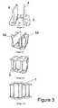
- the figures show an exemplary embodiment of the joining device (100, 100') that is formed by an essentially prismatic or cubic body comprising a first, top cover (1) and a second, bottom cover (2), each of which has a plurality of through holes (3) distributed around the perimeter (1,2) that match up with one another in position.
- the first and second covers (1,2) of the joining device (100) comprise a central opening (3A) that defines an open central space.
- the covers (1,2) of the joining device (100') do not have a central opening.
- the covers (1,2) are joined together by means of, at least, two transverse webs (4) and several inner (5) and outer (5A) stiffener reinforcements, which are arranged in perpendicular to the transverse covers (4).
- the inner space (6) defined by the webs (4) and the inner stiffeners (5) matches up with the open central space (3A) of the covers (1,2), thus defining a space that passes through the assembly.
- each through hole (3) is arranged in a quadrant delimited by the stiffener reinforcements (5,5A) and the webs (4).
- the joining device (100, 100') is especially intended for the purpose of connecting the rebars (201,201 A) of the columns (200,200A), thus meaning that connecting means to this end will be necessary, which in this practical embodiment are a plurality of coupling nuts (202).
- the aforementioned rebars (201,201 A) of the columns (200,200A) have threaded ends (threaded rods may also be welded onto the ends of the rebars).
- the materials used in this exemplary embodiment of the joining device (100, 100') are steels with a characteristic yield stress of at least 275 MPa.
- the connecting means formed by screws, nuts or threaded rods are to be made of high-strength steel with a grade of 10.9 or higher.
- the distance from the outer edges at right angles to the holes (3) is normally to be comprised between 20 and 50 mm, although it may be greater.
- the diameter of said holes (3) is preferably comprised between 25 and 27 mm, although they may be in a greater range comprised between 13 and 35 mm.
- the joining device (100, 100') comprises at least one hole (3) per corner and between one and three side holes, i.e. the holes (3) situated on the sides between two corner holes. All of the holes (3) are at an equal distance from those adjacent to them aligned along the same edge.
- the open central space (3A) is designed to carry out the following functions:
- the holes (3) situated along the edge may be slotted from their theoretical position in a direction perpendicular to the edge and towards it.
- a feature of this slotting is that if a horizontal force is present, causing a bending moment and shear force, the shear stress will only be resisted by means of friction and butting up against the compressed rebars due to the bending moment. Furthermore, if there is a pure bending force with a homogeneous cross-section (without fissures), the neutral fiber would pass through the middle zone and one half would be compressed; in this sense, said rebars would be exploited in order to transmit the shearing stresses that could exceed the friction.
- the holes (3) situated at the corners have double slotting that is analogous to that of the holes (3) along the edges upon which they are located, in both directions, whose purpose it the same as that of the latter.
- the use of slotted holes shall not always be necessary; in some instances the friction caused by the weight gravitating upon the column shall suffice, in which cases circular holes will be valid, with or without an increased radius. It will only be necessary at those points in the building having less weight gravitating upon them, in which case collaboration with the column may be necessary.
- the total dimensions of the joining device (100, 100') are variable in order to adapt to a plurality of cases in terms of column (200,200A) geometry.
- the following table shows a non-limiting example with the illustrative maximum and minimum dimensions, which are variables of each element making up the joining device (100, 100') as detailed in figure 2 .
- segments of column (200,200A) with different cross-sections are connected, one must always consider the cross-section of the segment to be situated on top of the junction, which in general is smaller and therefore more constraining.
- threaded rebars are used straight away.
- the rebars (201,201 A) end up face-to-face and a coupling nut (202) is used as a final joining element.
- said nut (202) is screwed all the way onto the lower segment of column (200), situated beneath the joining device (100, 100').
- the upper segment of column (200A) is then placed upon the joining device (100, 100'), the rebars thus ending up face-to-face, unscrewing on one side while screwing in on the other with one single motion.
- step (i) shows the welding of the stiffener reinforcements, specifically the outer stiffeners (5A) that are welded to the webs (4) and to the second, bottom cover (2).
- step (iii) shows how the inner stiffeners (5) are welded to the second, bottom cover (2), closing the assembly with step (iv) by welding the first, top cover (1), whereby first it is placed in position in order to subsequently weld to the webs and the stiffener reinforcements (5,5A), from the outside, at least all of that which does not end up confined in the space between the webs (4) and the inner stiffeners (5).
- step (iii) shows how the inner stiffeners (5) are welded to the second, bottom cover (2), closing the assembly with step (iv) by welding the first, top cover (1), whereby first it is placed in position in order to subsequently weld to the webs and the stiffener reinforcements (5,5A), from the outside, at least all of that which does not end up confined in the space between the webs (4) and the inner stiffeners (5).
- the holes (3) and, in the embodiment of figure 1 the open central space (3A)
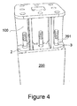
- the junction may be implemented very easily on site, as shown in figures 4 and 6 .
- the joining device (100, 100') is placed upon the end section of an existing column (200) with the ends of the rebars (201) of the existing column (200) passing through the holes (3) in the second, bottom cover (2) of the joining device (100, 100'), as shown specifically in figure 4 .
- the connecting means are placed, which in this particular embodiment are nuts (202) that are screwed all the way on, ensuring that there is space to support the next column (200A).
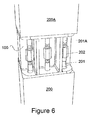
- the end of the next column (200A) rests upon the joining device (100, 100'), the ends of the rebars (201 A) of the next column (200A) ending up face-to-face with the rebars (201) of the existing column (200) by passing through the holes (3) in the first, top cover (1) of the joining device (100, 100'), the coupling nuts (202) then being able to join together the two rebars (201,201 A), unscrewing from one and screwing onto the other.
- the junction is thus completed with a single motion, guaranteeing the transmission of tensile force between the rebars (201,201 A) of each of the two sides, as shown in figure 6 .
- the means of connecting in this particular embodiment shown in figures 4 to 6 are embodied as a coupling nut (202).
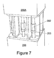
- a pretensioning effect may be achieved by following the process shown in said figures wherein first of all the joining device (100, 100') is placed on the springing point of the lower column (200). The next step consists of adding torque nuts (203) and screwing them all the way on; upon arriving at this point they are pretensioned. Once it has been pretensioned, the coupling nut (202) is added and screwed on. Then, the springing point of the top column (200A) is placed upon the device (100, 100'), and the coupling nut (202) is unscrewed, thus screwing it onto the next segment of rebar.
- the torque nut (203) is loosened, transmitting the stress to the top connection, and is unscrewed until it is pressed against the coupling nut (202), acting as a locknut, as shown in figure 7 .
- the effect may be increased even more with another nut in the upper segment of rebar, loosening it as well and doubling the pretensioning effect.
- Figure 8 shows a second embodiment of the connecting means.
- This second embodiment is intended not to transmit compressive stress, beyond prior preloading and pretensioning, and to avoid problems of tolerances, threads meeting, and so on.
- It is a joining element (204) formed by two structural steel tubes (204A) welded to two concrete-reinforcing corrugated steel bars (204B), forming a doubly-symmetrical bifurcation. The ends of the column rebars of consecutive segments (200,200A) pass through the inside of the tubes (204A) and are tightened with a nut (204C) on the other side, completing the junction.
- this embodiment of the junction is simple: first the column is placed and afterwards the piece with the necessary connecting elements, after which the nut of the lower segment is put on, closing it, and then the upper segment is placed, the nut is placed, and the junction is thus completed.
- Figure 9 shows a third embodiment of the connecting means.
- the form of the male-female junction consists of a threaded rod (205) and a coupling nut (205A) into which it is screwed. It has the advantage of making it possible to progressively bring them closer together, and there is an increase in tolerance that makes it easier for the top and bottom screws to meet, where it is possible for the position of the beginning of the threads to not match up and require a bit more play.
- Assembly is carried out by first placing the joining device (100) and the coupling nuts (205A), and then screwing the threaded rod (205) into the left over section of the nut (205A), and unscrewing the coupling nut (205A) until the end section of threaded rod meets the opposing coupling nut (205A), and both screws (205A) are screwed on and tightened, completing the junction.
Priority Applications (5)
| Application Number | Priority Date | Filing Date | Title |
|---|---|---|---|
| EP14382261.7A EP2966236A1 (de) | 2014-07-07 | 2014-07-07 | Verbindungsvorrichtung für Stahlbeton-Fertigtsäulen mit trockener Fuge |
| MX2017000106A MX2017000106A (es) | 2014-07-07 | 2015-06-25 | Dispositivo de union para pilares prefabricados de hormigon armado con junta seca. |
| US15/324,361 US10400438B2 (en) | 2014-07-07 | 2015-06-25 | Joining device for precast reinforced concrete columns with a dry joint |
| PCT/ES2015/070497 WO2016005631A1 (es) | 2014-07-07 | 2015-06-25 | Dispositivo de unión para pilares prefabricados de hormigón armado con junta seca |
| CL2016003361A CL2016003361A1 (es) | 2014-07-07 | 2016-12-28 | Proceso, uso y dispositivo de unión entre dos pilares de hormigón armado prefabricados, comprende una primera y segunda tapa, paralelas entre sí; una pluralidad de agujeros pasantes y en posición coincidente entre sí; dos almas transversales y refuerzos rigidizadores que se disponen perpendiculares a las tapas; y dispositivo con unos medios de conexión entre los extremos de las armaduras. |
Applications Claiming Priority (1)
| Application Number | Priority Date | Filing Date | Title |
|---|---|---|---|
| EP14382261.7A EP2966236A1 (de) | 2014-07-07 | 2014-07-07 | Verbindungsvorrichtung für Stahlbeton-Fertigtsäulen mit trockener Fuge |
Publications (1)
| Publication Number | Publication Date |
|---|---|
| EP2966236A1 true EP2966236A1 (de) | 2016-01-13 |
Family
ID=51492911
Family Applications (1)
| Application Number | Title | Priority Date | Filing Date |
|---|---|---|---|
| EP14382261.7A Withdrawn EP2966236A1 (de) | 2014-07-07 | 2014-07-07 | Verbindungsvorrichtung für Stahlbeton-Fertigtsäulen mit trockener Fuge |
Country Status (5)
| Country | Link |
|---|---|
| US (1) | US10400438B2 (de) |
| EP (1) | EP2966236A1 (de) |
| CL (1) | CL2016003361A1 (de) |
| MX (1) | MX2017000106A (de) |
| WO (1) | WO2016005631A1 (de) |
Cited By (11)
| Publication number | Priority date | Publication date | Assignee | Title |
|---|---|---|---|---|
| CN105863167A (zh) * | 2016-05-29 | 2016-08-17 | 湖南大学 | 一种可拆卸装配式圆钢管混凝土柱 |
| CN106381926A (zh) * | 2016-10-28 | 2017-02-08 | 湖南大学 | 一种可拆卸的装配式钢筋混凝土柱与柱拼接节点 |
| CN106836657A (zh) * | 2017-03-17 | 2017-06-13 | 北京市建筑设计研究院有限公司 | 钢筋连接用灌浆套筒或装置在灌浆不足时的修补装置及方法 |
| CN108571069A (zh) * | 2018-05-17 | 2018-09-25 | 曙光建设有限公司 | 一种适用于预制装配建筑的框架柱连接节点 |
| CN109057169A (zh) * | 2018-09-10 | 2018-12-21 | 浙江南洋水泥制品有限公司 | 一种预制水泥构件的钢筋连接结构 |
| CN111236536A (zh) * | 2020-02-25 | 2020-06-05 | 东南大学 | 一种自立预制柱混合连接及其施工方法 |
| CN112982830A (zh) * | 2021-03-19 | 2021-06-18 | 中铁六局集团有限公司 | 一种装配式框架柱及施工方法 |
| CN113323482A (zh) * | 2021-05-31 | 2021-08-31 | 重庆大学 | 一种附加震后可更换的防屈曲耗能机构的柱脚节点 |
| CN113700154A (zh) * | 2021-08-26 | 2021-11-26 | 上海宝冶集团有限公司 | 一种带有连接夹具的预制装配式柱柱连接节点 |
| CN114922495A (zh) * | 2022-06-02 | 2022-08-19 | 华南理工大学 | 一种快速装配式预制柱及其连接节点 |
| CN115030306A (zh) * | 2022-04-28 | 2022-09-09 | 湖南大学 | 柱端变形可控且柱身易更换的柱组件 |
Families Citing this family (8)
| Publication number | Priority date | Publication date | Assignee | Title |
|---|---|---|---|---|
| DE102016106526A1 (de) * | 2016-04-08 | 2017-10-12 | Wobben Properties Gmbh | Verbindungskörper und Verfahren zum Verbinden von Teilringsegmenten |
| JP1583269S (de) * | 2016-09-26 | 2017-08-07 | ||
| JP1583268S (de) * | 2016-09-26 | 2017-08-07 | ||
| KR101919583B1 (ko) * | 2018-05-10 | 2018-11-16 | 서울대학교산학협력단 | 자립형 pc 기둥 접합부 |
| CN109024248A (zh) * | 2018-08-10 | 2018-12-18 | 苏交科集团股份有限公司 | 自动嵌入式节段预制墩柱结构及连接方法 |
| EP4223949A1 (de) * | 2019-07-26 | 2023-08-09 | DLC Consulting S.r.l. | Trockenverbindungssystem von fertigbauteilen |
| IT201900012978A1 (it) * | 2019-07-26 | 2021-01-26 | Dlc Consulting S R L | Sistema di connessione a secco di elementi prefabbricati |
| CN112832371B (zh) * | 2021-01-12 | 2021-12-28 | 江南大学 | 一种含榫卯构造的装配式梁柱耗能节点单元 |
Citations (9)
| Publication number | Priority date | Publication date | Assignee | Title |
|---|---|---|---|---|
| DE7624523U1 (de) * | 1976-08-04 | 1977-09-15 | Dyckerhoff & Widmann Ag, 8000 Muenchen | Vorrichtung zur zugfesten verbindung von vorgefertigten bauteilen, vorzugsweise betonfertigteilen |
| FR2367158A1 (fr) * | 1976-10-05 | 1978-05-05 | Gram Sa | Dispositif d'accouplement pour element en beton arme ou precontraint |
| US4295308A (en) * | 1979-10-26 | 1981-10-20 | K S L Corporation | Pole base assembly, bolt circle adaptor |
| JP2008233079A (ja) | 2007-03-16 | 2008-10-02 | Kofukin Seimitsu Kogyo (Shenzhen) Yugenkoshi | 電離真空計 |
| WO2012056101A1 (en) * | 2010-10-26 | 2012-05-03 | Peikko Group Oy | Column shoe |
| KR101228012B1 (ko) * | 2011-08-09 | 2013-02-14 | (주)케이에이치하우징솔루션스 | Pc기둥 접합구조 |
| JP5154962B2 (ja) | 2008-02-01 | 2013-02-27 | 株式会社竹中工務店 | プレキャストコンクリート構造部材の接合構造、建物、及び建物の施工方法 |
| JP5160907B2 (ja) | 2008-01-08 | 2013-03-13 | 株式会社竹中工務店 | プレキャストコンクリート柱梁部材の接合構造、建物、及び建物の施工方法 |
| KR101260392B1 (ko) | 2011-12-07 | 2013-05-07 | (주)케이에이치하우징솔루션스 | 저모멘트존에서 연결되는 pc기둥 및 보유닛의 조립식 구조 |
Family Cites Families (20)
| Publication number | Priority date | Publication date | Assignee | Title |
|---|---|---|---|---|
| US2724261A (en) * | 1951-05-24 | 1955-11-22 | Egil M Rensaa | Precast column attaching means |
| US3572223A (en) * | 1969-08-26 | 1971-03-23 | Ralph L Vierregger | Laterally-disengageable highway marker assembly |
| US3745731A (en) * | 1971-01-27 | 1973-07-17 | M Simpson | Interlocking building construction |
| US3785097A (en) * | 1972-11-06 | 1974-01-15 | W Seymour | Adjustable anchor bolt & block building and leveling means |
| CA1009856A (en) * | 1974-12-02 | 1977-05-10 | West's Piling And Construction Company Limited | Pile connecting device |
| GB1524252A (en) * | 1975-05-13 | 1978-09-06 | Ccl Systems Ltd | Joining concrete members in buildings |
| JPS5827365B2 (ja) | 1978-02-15 | 1983-06-09 | フランク オツト− シルバンデル | コンクリ−ト棒状体の継手 |
| US4330970A (en) * | 1979-10-23 | 1982-05-25 | Copreal S.A. | Building structure and steel parts for same |
| DE3526449A1 (de) | 1985-07-24 | 1987-02-05 | Dimitri Papanikolaou | Vorgefertigtes bauelement fuer die erstellung von gebaeuden sowie verfahren unter dessen verwendung |
| US4781006A (en) * | 1986-11-10 | 1988-11-01 | Haynes Harvey H | Bolted chord bar connector for concrete construction |
| US4938635A (en) * | 1986-12-17 | 1990-07-03 | Russell James B | Concrete beams and connecting means therefor |
| DE3915711A1 (de) | 1989-01-31 | 1990-11-15 | Ibs Integriertes Bauen | Bauelement zur erstellung von gebaeuden, gebaeudeteilen od.dgl. |
| DE9114329U1 (de) | 1991-11-16 | 1992-01-16 | Ibs Gesellschaft Fuer Integriertes Bauen Mbh, 4050 Moenchengladbach, De | |
| US5669196A (en) * | 1996-02-13 | 1997-09-23 | Dahl; Kjell L. | Eye bolt reinforcement steel coupler |
| NO323943B1 (no) * | 2005-10-13 | 2007-07-23 | Sb Produksjon As | Sammenfoyningssystem og anvendelse av dette |
| FI118186B (fi) | 2005-12-27 | 2007-08-15 | Peikko Finland Oy | Pilarikenkä |
| DE102006023296A1 (de) | 2006-05-18 | 2007-11-22 | Krummel, Gerhard, Dipl.-Ing. | Vorrichtung zur Befestigung einer Betonstütze auf einem Fundament, insbesondere einem Betonfundament |
| US20090263189A9 (en) * | 2007-04-13 | 2009-10-22 | Kari Koivunen | Joint for reinforced concrete pile sections |
| US20100322717A1 (en) * | 2009-06-19 | 2010-12-23 | Standard Concrete Products, Inc. | Pile Splice Assemblies, Pile Systems Involving Such Assemblies and Methods for Splicing Piles |
| US9057170B2 (en) * | 2009-07-01 | 2015-06-16 | Nu Tech Ventures, Inc. | Continuously prestressed concrete pile splice |
-
2014
- 2014-07-07 EP EP14382261.7A patent/EP2966236A1/de not_active Withdrawn
-
2015
- 2015-06-25 US US15/324,361 patent/US10400438B2/en not_active Expired - Fee Related
- 2015-06-25 WO PCT/ES2015/070497 patent/WO2016005631A1/es active Application Filing
- 2015-06-25 MX MX2017000106A patent/MX2017000106A/es unknown
-
2016
- 2016-12-28 CL CL2016003361A patent/CL2016003361A1/es unknown
Patent Citations (9)
| Publication number | Priority date | Publication date | Assignee | Title |
|---|---|---|---|---|
| DE7624523U1 (de) * | 1976-08-04 | 1977-09-15 | Dyckerhoff & Widmann Ag, 8000 Muenchen | Vorrichtung zur zugfesten verbindung von vorgefertigten bauteilen, vorzugsweise betonfertigteilen |
| FR2367158A1 (fr) * | 1976-10-05 | 1978-05-05 | Gram Sa | Dispositif d'accouplement pour element en beton arme ou precontraint |
| US4295308A (en) * | 1979-10-26 | 1981-10-20 | K S L Corporation | Pole base assembly, bolt circle adaptor |
| JP2008233079A (ja) | 2007-03-16 | 2008-10-02 | Kofukin Seimitsu Kogyo (Shenzhen) Yugenkoshi | 電離真空計 |
| JP5160907B2 (ja) | 2008-01-08 | 2013-03-13 | 株式会社竹中工務店 | プレキャストコンクリート柱梁部材の接合構造、建物、及び建物の施工方法 |
| JP5154962B2 (ja) | 2008-02-01 | 2013-02-27 | 株式会社竹中工務店 | プレキャストコンクリート構造部材の接合構造、建物、及び建物の施工方法 |
| WO2012056101A1 (en) * | 2010-10-26 | 2012-05-03 | Peikko Group Oy | Column shoe |
| KR101228012B1 (ko) * | 2011-08-09 | 2013-02-14 | (주)케이에이치하우징솔루션스 | Pc기둥 접합구조 |
| KR101260392B1 (ko) | 2011-12-07 | 2013-05-07 | (주)케이에이치하우징솔루션스 | 저모멘트존에서 연결되는 pc기둥 및 보유닛의 조립식 구조 |
Cited By (14)
| Publication number | Priority date | Publication date | Assignee | Title |
|---|---|---|---|---|
| CN105863167A (zh) * | 2016-05-29 | 2016-08-17 | 湖南大学 | 一种可拆卸装配式圆钢管混凝土柱 |
| CN106381926A (zh) * | 2016-10-28 | 2017-02-08 | 湖南大学 | 一种可拆卸的装配式钢筋混凝土柱与柱拼接节点 |
| CN106836657A (zh) * | 2017-03-17 | 2017-06-13 | 北京市建筑设计研究院有限公司 | 钢筋连接用灌浆套筒或装置在灌浆不足时的修补装置及方法 |
| CN106836657B (zh) * | 2017-03-17 | 2022-03-25 | 北京市建筑设计研究院有限公司 | 钢筋连接用灌浆套筒或装置在灌浆不足时的修补装置及方法 |
| CN108571069A (zh) * | 2018-05-17 | 2018-09-25 | 曙光建设有限公司 | 一种适用于预制装配建筑的框架柱连接节点 |
| CN109057169B (zh) * | 2018-09-10 | 2021-04-13 | 安徽省英剑科技发展有限公司 | 一种预制水泥构件的钢筋连接结构 |
| CN109057169A (zh) * | 2018-09-10 | 2018-12-21 | 浙江南洋水泥制品有限公司 | 一种预制水泥构件的钢筋连接结构 |
| CN111236536A (zh) * | 2020-02-25 | 2020-06-05 | 东南大学 | 一种自立预制柱混合连接及其施工方法 |
| CN112982830A (zh) * | 2021-03-19 | 2021-06-18 | 中铁六局集团有限公司 | 一种装配式框架柱及施工方法 |
| CN113323482A (zh) * | 2021-05-31 | 2021-08-31 | 重庆大学 | 一种附加震后可更换的防屈曲耗能机构的柱脚节点 |
| CN113323482B (zh) * | 2021-05-31 | 2022-08-05 | 重庆大学 | 一种附加震后可更换的防屈曲耗能机构的柱脚节点 |
| CN113700154A (zh) * | 2021-08-26 | 2021-11-26 | 上海宝冶集团有限公司 | 一种带有连接夹具的预制装配式柱柱连接节点 |
| CN115030306A (zh) * | 2022-04-28 | 2022-09-09 | 湖南大学 | 柱端变形可控且柱身易更换的柱组件 |
| CN114922495A (zh) * | 2022-06-02 | 2022-08-19 | 华南理工大学 | 一种快速装配式预制柱及其连接节点 |
Also Published As
| Publication number | Publication date |
|---|---|
| US10400438B2 (en) | 2019-09-03 |
| WO2016005631A1 (es) | 2016-01-14 |
| MX2017000106A (es) | 2017-04-27 |
| CL2016003361A1 (es) | 2017-03-24 |
| US20170183861A1 (en) | 2017-06-29 |
Similar Documents
| Publication | Publication Date | Title |
|---|---|---|
| US10400438B2 (en) | Joining device for precast reinforced concrete columns with a dry joint | |
| US10378199B2 (en) | Dry joint joining device between columns and beams of precast reinforced concrete | |
| CN103088920B (zh) | 一种先张法预应力叠合梁结构体系及其施工方法 | |
| CN108729564B (zh) | 装配式建筑体系 | |
| KR101030419B1 (ko) | 수직부재와 수평부재의 결합구조 | |
| EP2559817A2 (de) | Einstellbares System für eine eingebettete Zusammenfügung von vorgefertigten Betonelementen für Gebäudestrukturen, und Verfahren zur Durchführung der Zusammenfügung von vorgefertigten Betonelementen | |
| KR102274029B1 (ko) | 콘크리트 기둥 내진 보강 방법 | |
| KR100858963B1 (ko) | 프리캐스트 철근콘크리트 보용 연결블록, 그 연결블록이결합된 고강도 프리캐스트 철근콘크리트 보의 제조방법 및그 연결블록이 결합된 고강도 프리캐스트 철근콘크리트보와 기둥의 접합 방법 | |
| CN108035443B (zh) | 一种双钢板剪力墙与楼板的连接方法 | |
| CN115110669A (zh) | 一种预制装配式剪力墙及其施工方法 | |
| KR100343960B1 (ko) | 강콘크리트 구조시스템 | |
| DE102007057291A1 (de) | Verfahren zur Herstellung einer Eckverbindung für Beton-Fertigteile | |
| WO2014182262A1 (en) | Beams, columns and beam-column joints structural elements innovation | |
| KR100245056B1 (ko) | 철근콘크리트기둥용 기성철근조립체 및 그를 이용한 기둥의 시공방법 | |
| DE102009022828B4 (de) | Fachwerkträger einschließlich eines unterspannten Trägers sowie ein zugehöriges Verfahren zur Herstellung | |
| KR101846501B1 (ko) | 철근래티스 콘크리트 스틸합성 박스형 기둥 구조체 | |
| CN107023078B (zh) | 装配现浇组合式叠合箱网梁楼盖及施工方法 | |
| CN115110671A (zh) | 一种组合装配式剪力墙及其施工方法 | |
| JP5439016B2 (ja) | 埋設型枠 | |
| JP5050221B2 (ja) | 床スラブ | |
| WO2014076716A1 (en) | A wall system of parallelepiped precast building panel | |
| WO2021014616A1 (ja) | 鉄筋継手および鉄筋組立体、並びにプレキャスト鉄筋コンクリート体 | |
| JP6978901B2 (ja) | プレキャストコンクリート梁部材の接合構造および接合方法 | |
| JP6888944B2 (ja) | 複合梁における異種材料の接合方法と接合構造 | |
| JP6921413B2 (ja) | 鉄筋継手および鉄筋組立体、並びにプレキャスト鉄筋コンクリート体 |
Legal Events
| Date | Code | Title | Description |
|---|---|---|---|
| PUAI | Public reference made under article 153(3) epc to a published international application that has entered the european phase |
Free format text: ORIGINAL CODE: 0009012 |
|
| AK | Designated contracting states |
Kind code of ref document: A1 Designated state(s): AL AT BE BG CH CY CZ DE DK EE ES FI FR GB GR HR HU IE IS IT LI LT LU LV MC MK MT NL NO PL PT RO RS SE SI SK SM TR |
|
| AX | Request for extension of the european patent |
Extension state: BA ME |
|
| 17P | Request for examination filed |
Effective date: 20160622 |
|
| RBV | Designated contracting states (corrected) |
Designated state(s): AL AT BE BG CH CY CZ DE DK EE ES FI FR GB GR HR HU IE IS IT LI LT LU LV MC MK MT NL NO PL PT RO RS SE SI SK SM TR |
|
| 17Q | First examination report despatched |
Effective date: 20160726 |
|
| STAA | Information on the status of an ep patent application or granted ep patent |
Free format text: STATUS: EXAMINATION IS IN PROGRESS |
|
| STAA | Information on the status of an ep patent application or granted ep patent |
Free format text: STATUS: EXAMINATION IS IN PROGRESS |
|
| STAA | Information on the status of an ep patent application or granted ep patent |
Free format text: STATUS: THE APPLICATION IS DEEMED TO BE WITHDRAWN |
|
| 18D | Application deemed to be withdrawn |
Effective date: 20210316 |