EP2965947A1 - Fahrtrichtungsanzeigemodul und Außenrückspiegelanordnung - Google Patents
Fahrtrichtungsanzeigemodul und Außenrückspiegelanordnung Download PDFInfo
- Publication number
- EP2965947A1 EP2965947A1 EP14176666.7A EP14176666A EP2965947A1 EP 2965947 A1 EP2965947 A1 EP 2965947A1 EP 14176666 A EP14176666 A EP 14176666A EP 2965947 A1 EP2965947 A1 EP 2965947A1
- Authority
- EP
- European Patent Office
- Prior art keywords
- light guide
- light
- direction indicator
- indicator module
- mirror assembly
- Prior art date
- Legal status (The legal status is an assumption and is not a legal conclusion. Google has not performed a legal analysis and makes no representation as to the accuracy of the status listed.)
- Granted
Links
Images



Classifications
-
- B—PERFORMING OPERATIONS; TRANSPORTING
- B60—VEHICLES IN GENERAL
- B60Q—ARRANGEMENT OF SIGNALLING OR LIGHTING DEVICES, THE MOUNTING OR SUPPORTING THEREOF OR CIRCUITS THEREFOR, FOR VEHICLES IN GENERAL
- B60Q1/00—Arrangement of optical signalling or lighting devices, the mounting or supporting thereof or circuits therefor
- B60Q1/26—Arrangement of optical signalling or lighting devices, the mounting or supporting thereof or circuits therefor the devices being primarily intended to indicate the vehicle, or parts thereof, or to give signals, to other traffic
- B60Q1/2661—Arrangement of optical signalling or lighting devices, the mounting or supporting thereof or circuits therefor the devices being primarily intended to indicate the vehicle, or parts thereof, or to give signals, to other traffic mounted on parts having other functions
- B60Q1/2665—Arrangement of optical signalling or lighting devices, the mounting or supporting thereof or circuits therefor the devices being primarily intended to indicate the vehicle, or parts thereof, or to give signals, to other traffic mounted on parts having other functions on rear-view mirrors
-
- B—PERFORMING OPERATIONS; TRANSPORTING
- B60—VEHICLES IN GENERAL
- B60Q—ARRANGEMENT OF SIGNALLING OR LIGHTING DEVICES, THE MOUNTING OR SUPPORTING THEREOF OR CIRCUITS THEREFOR, FOR VEHICLES IN GENERAL
- B60Q1/00—Arrangement of optical signalling or lighting devices, the mounting or supporting thereof or circuits therefor
- B60Q1/26—Arrangement of optical signalling or lighting devices, the mounting or supporting thereof or circuits therefor the devices being primarily intended to indicate the vehicle, or parts thereof, or to give signals, to other traffic
- B60Q1/34—Arrangement of optical signalling or lighting devices, the mounting or supporting thereof or circuits therefor the devices being primarily intended to indicate the vehicle, or parts thereof, or to give signals, to other traffic for indicating change of drive direction
-
- B—PERFORMING OPERATIONS; TRANSPORTING
- B60—VEHICLES IN GENERAL
- B60R—VEHICLES, VEHICLE FITTINGS, OR VEHICLE PARTS, NOT OTHERWISE PROVIDED FOR
- B60R1/00—Optical viewing arrangements; Real-time viewing arrangements for drivers or passengers using optical image capturing systems, e.g. cameras or video systems specially adapted for use in or on vehicles
- B60R1/02—Rear-view mirror arrangements
- B60R1/06—Rear-view mirror arrangements mounted on vehicle exterior
-
- B—PERFORMING OPERATIONS; TRANSPORTING
- B60—VEHICLES IN GENERAL
- B60R—VEHICLES, VEHICLE FITTINGS, OR VEHICLE PARTS, NOT OTHERWISE PROVIDED FOR
- B60R1/00—Optical viewing arrangements; Real-time viewing arrangements for drivers or passengers using optical image capturing systems, e.g. cameras or video systems specially adapted for use in or on vehicles
- B60R1/12—Mirror assemblies combined with other articles, e.g. clocks
- B60R1/1207—Mirror assemblies combined with other articles, e.g. clocks with lamps; with turn indicators
-
- F—MECHANICAL ENGINEERING; LIGHTING; HEATING; WEAPONS; BLASTING
- F21—LIGHTING
- F21S—NON-PORTABLE LIGHTING DEVICES; SYSTEMS THEREOF; VEHICLE LIGHTING DEVICES SPECIALLY ADAPTED FOR VEHICLE EXTERIORS
- F21S43/00—Signalling devices specially adapted for vehicle exteriors, e.g. brake lamps, direction indicator lights or reversing lights
- F21S43/20—Signalling devices specially adapted for vehicle exteriors, e.g. brake lamps, direction indicator lights or reversing lights characterised by refractors, transparent cover plates, light guides or filters
- F21S43/235—Light guides
- F21S43/236—Light guides characterised by the shape of the light guide
- F21S43/237—Light guides characterised by the shape of the light guide rod-shaped
-
- F—MECHANICAL ENGINEERING; LIGHTING; HEATING; WEAPONS; BLASTING
- F21—LIGHTING
- F21S—NON-PORTABLE LIGHTING DEVICES; SYSTEMS THEREOF; VEHICLE LIGHTING DEVICES SPECIALLY ADAPTED FOR VEHICLE EXTERIORS
- F21S43/00—Signalling devices specially adapted for vehicle exteriors, e.g. brake lamps, direction indicator lights or reversing lights
- F21S43/20—Signalling devices specially adapted for vehicle exteriors, e.g. brake lamps, direction indicator lights or reversing lights characterised by refractors, transparent cover plates, light guides or filters
- F21S43/235—Light guides
- F21S43/236—Light guides characterised by the shape of the light guide
- F21S43/239—Light guides characterised by the shape of the light guide plate-shaped
-
- F—MECHANICAL ENGINEERING; LIGHTING; HEATING; WEAPONS; BLASTING
- F21—LIGHTING
- F21S—NON-PORTABLE LIGHTING DEVICES; SYSTEMS THEREOF; VEHICLE LIGHTING DEVICES SPECIALLY ADAPTED FOR VEHICLE EXTERIORS
- F21S43/00—Signalling devices specially adapted for vehicle exteriors, e.g. brake lamps, direction indicator lights or reversing lights
- F21S43/20—Signalling devices specially adapted for vehicle exteriors, e.g. brake lamps, direction indicator lights or reversing lights characterised by refractors, transparent cover plates, light guides or filters
- F21S43/235—Light guides
- F21S43/242—Light guides characterised by the emission area
- F21S43/243—Light guides characterised by the emission area emitting light from one or more of its extremities
-
- F—MECHANICAL ENGINEERING; LIGHTING; HEATING; WEAPONS; BLASTING
- F21—LIGHTING
- F21S—NON-PORTABLE LIGHTING DEVICES; SYSTEMS THEREOF; VEHICLE LIGHTING DEVICES SPECIALLY ADAPTED FOR VEHICLE EXTERIORS
- F21S43/00—Signalling devices specially adapted for vehicle exteriors, e.g. brake lamps, direction indicator lights or reversing lights
- F21S43/20—Signalling devices specially adapted for vehicle exteriors, e.g. brake lamps, direction indicator lights or reversing lights characterised by refractors, transparent cover plates, light guides or filters
- F21S43/235—Light guides
- F21S43/242—Light guides characterised by the emission area
- F21S43/245—Light guides characterised by the emission area emitting light from one or more of its major surfaces
-
- F—MECHANICAL ENGINEERING; LIGHTING; HEATING; WEAPONS; BLASTING
- F21—LIGHTING
- F21S—NON-PORTABLE LIGHTING DEVICES; SYSTEMS THEREOF; VEHICLE LIGHTING DEVICES SPECIALLY ADAPTED FOR VEHICLE EXTERIORS
- F21S43/00—Signalling devices specially adapted for vehicle exteriors, e.g. brake lamps, direction indicator lights or reversing lights
- F21S43/20—Signalling devices specially adapted for vehicle exteriors, e.g. brake lamps, direction indicator lights or reversing lights characterised by refractors, transparent cover plates, light guides or filters
- F21S43/2605—Refractors
- F21S43/2621—Refractors characterised by the properties of the light beam shaping surface
- F21S43/26211—Refractors characterised by the properties of the light beam shaping surface redirecting, i.e. substantially only changing light propagation direction
-
- F—MECHANICAL ENGINEERING; LIGHTING; HEATING; WEAPONS; BLASTING
- F21—LIGHTING
- F21S—NON-PORTABLE LIGHTING DEVICES; SYSTEMS THEREOF; VEHICLE LIGHTING DEVICES SPECIALLY ADAPTED FOR VEHICLE EXTERIORS
- F21S43/00—Signalling devices specially adapted for vehicle exteriors, e.g. brake lamps, direction indicator lights or reversing lights
- F21S43/20—Signalling devices specially adapted for vehicle exteriors, e.g. brake lamps, direction indicator lights or reversing lights characterised by refractors, transparent cover plates, light guides or filters
- F21S43/281—Materials thereof; Structures thereof; Properties thereof; Coatings thereof
- F21S43/28135—Structures encapsulating the light source
-
- G—PHYSICS
- G02—OPTICS
- G02B—OPTICAL ELEMENTS, SYSTEMS OR APPARATUS
- G02B6/00—Light guides; Structural details of arrangements comprising light guides and other optical elements, e.g. couplings
-
- G—PHYSICS
- G02—OPTICS
- G02B—OPTICAL ELEMENTS, SYSTEMS OR APPARATUS
- G02B6/00—Light guides; Structural details of arrangements comprising light guides and other optical elements, e.g. couplings
- G02B6/0001—Light guides; Structural details of arrangements comprising light guides and other optical elements, e.g. couplings specially adapted for lighting devices or systems
- G02B6/0011—Light guides; Structural details of arrangements comprising light guides and other optical elements, e.g. couplings specially adapted for lighting devices or systems the light guides being planar or of plate-like form
- G02B6/0075—Arrangements of multiple light guides
- G02B6/0078—Side-by-side arrangements, e.g. for large area displays
-
- B—PERFORMING OPERATIONS; TRANSPORTING
- B60—VEHICLES IN GENERAL
- B60Q—ARRANGEMENT OF SIGNALLING OR LIGHTING DEVICES, THE MOUNTING OR SUPPORTING THEREOF OR CIRCUITS THEREFOR, FOR VEHICLES IN GENERAL
- B60Q1/00—Arrangement of optical signalling or lighting devices, the mounting or supporting thereof or circuits therefor
- B60Q1/26—Arrangement of optical signalling or lighting devices, the mounting or supporting thereof or circuits therefor the devices being primarily intended to indicate the vehicle, or parts thereof, or to give signals, to other traffic
- B60Q1/2696—Mounting of devices using LEDs
Definitions
- the present invention relates to a direction indicator module for an exterior rearview mirror assembly for a motor vehicle and an exterior rearview mirror assembly.
- FIG. 6 shows by way of example such an exterior rearview mirror arrangement 100, which has a mirror head 300 which can be pivoted relative to a mirror base 200.
- the mirror head 300 includes a housing 400 supporting at least a mirror (not shown) and a turn signal module 400.
- the light windows serve as light guides, as in the EP 0 858 932 B2 described, is not easy. Namely, the light windows serve as light guides for transporting light from a coupling-in point to a plurality of outcoupling points provided in the light guide, so that the luminance in an end coupling-out region or radiation area can no longer meet legal requirements.
- the object of the present invention is to provide a direction indicator module for an exterior rearview mirror assembly for a motor vehicle, which overcomes the disadvantages of the prior art. In particular, it should be easy to produce, while meeting both aesthetic and safety requirements.
- a direction indicator module for an exterior rearview mirror assembly for a motor vehicle comprising at least one light source, a first plurality of Lichtauskoppelstellen comprehensive light guide and a second radiating into a single Lichtauskoppel Scheme optical fiber, the light source a first radiation member at a first end in the first light guide and a second radiation part at a first end coupled into the second light guide, and the Lichtauskoppel Complex is disposed in a region of the first end of the first light guide opposite the second end of the first light guide.
- the light extraction points over the entire length of the first light guide between the first and second ends, in particular evenly distributed and / or provided via optical elements.
- the first light guide is formed together with the second light guide, a module housing and / or the optical elements, preferably as a 1K injection molded part.
- the second end of the second light guide ends before or in the Lichtauskoppel Scheme, wherein preferably a gap between the second end of the second light guide and the Lichtauskoppel Scheme is provided.
- Embodiments of the invention are also characterized in that the first and the second optical fiber extend at least partially parallel.
- the invention also provides an exterior rearview mirror assembly for a motor vehicle with a mirror head pivotable relative to a mirror base, wherein at least one mirror and a direction indicator module according to the invention are provided in the housing of the mirror head.
- the housing of the mirror head has a light exit opening, which is filled at least by the first light guide.
- the direction indicator module is detachably connected to the housing of the mirror head, in particular via the housing module and / or by means of a snap connection.
- the invention is therefore based on the surprising finding that the two optical fiber functions of a direction indicator module, namely on the one hand to fulfill design wishes and on the other to fulfill a legally determined illumination, can be provided by two light guides, but preferably formed in one are.
- a first optical fiber represents a design optical fiber with integrated, design-related optics or decoupling points, while a second optical fiber represents a functional fiber optic without design-related optics or decoupling.
- the two light guides are also designed combined with a lens.
- the unit of the two light guides can be formed as a one-component injection molded part be, preferably together with a housing via which the direction indicator module is connectable to an exterior rearview mirror assembly.
- FIG. 1 shows an inventive direction indicator module, which is often referred to simply as a turn signal module 1.
- This turn signal module 1 comprises not only a housing part 2 and a first optical waveguide 3, but also a second optical waveguide 5.
- the first optical waveguide 3 represents a design optical waveguide with a plurality of outcoupling points, for example in the form of a profiling in the sense of EP 0 858 932 B2 light one in the FIG. 1 not shown light source, which comprises at least one LED, succeeded in one in the FIG. 1 shown on the left, first end into the first light guide 3 and loses on its way to the opposite end of the first end second end, in the FIG.
- the second light guide 5 is therefore also referred to as a functional light guide, wherein it is used with light from the light source at its first, left in the FIG. 1 shown end can be acted upon, which he gives essentially without losses in the radiating 9, so that the radiating 9 actually makes the ECE R6 enough.
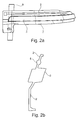
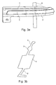
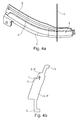
- FIGS. 2a . 3a and 4a make views according to FIG. 1 in which additionally each a sectional plane is shown, and the corresponding sectional views can be found in FIG. 2b . 3b or 4b.
- the Relatiwerlauf the two light guides 2, 3 can be seen. More precisely, the two light guides 3, 5 run parallel from their respective first end 3 'or 5' over a large part of the indicator module 1, and only at the second end 5 "of the second light guide 5 does this approach the second end 3" of the first light guide 3, in order to introduce light beams 11 into the emission area 9 via a gap 7.
- the second light guide can also open directly into the emission area of the first light guide.
- FIGS. 2a . 3a and 4b Furthermore, the geometry of the housing part 2 can be removed, which is formed together with the two light guides 3 and 5 as an injection molded part.
- FIG. 5 schematically indicates how light is coupled into the first end 3 'of the first optical waveguide 3 and into the first end 5' of the second optical waveguide 5 via a light source 13.
- light extraction points 15 are indicated in the first light guide 3.
- Not visible in FIG. 5 are the respective second ends of the two light guides 3, 5, in this regard, in particular to the FIGS. 4a and 4b is referenced.
- the turn signal module 1 can in the usual way, such as in the EP 0 858 932 B2 described, in an exterior rearview mirror assembly (not shown) are introduced. It is distinguished by its diverse design options over the first Optical fiber 3 without loss of luminance in the emission area 9 due to the second light guide 5, which is formed together with the first light guide 3 from.
Landscapes
- Engineering & Computer Science (AREA)
- General Engineering & Computer Science (AREA)
- Mechanical Engineering (AREA)
- Physics & Mathematics (AREA)
- Multimedia (AREA)
- General Physics & Mathematics (AREA)
- Optics & Photonics (AREA)
- Lighting Device Outwards From Vehicle And Optical Signal (AREA)
- Non-Portable Lighting Devices Or Systems Thereof (AREA)
Abstract
Description
- Die vorliegende Erfindung betrifft ein Fahrtrichtungsanzeigemodul für eine Außenrückblickspiegelanordnung für ein Kraftfahrzeug und eine Außenrückblickspiegelanordnung.
- Außenrückblickspiegelanordnungen für Kraftfahrzeuge sind in Stand der Technik vielfältig bekannt. Figur 6 zeigt beispielhaft solch eine Außenrückblickspiegelanordnungen 100, die einen gegenüber einem Spiegelfuß 200 verschwenkbaren Spiegelkopf 300 aufweist. Der Spiegelkopf 300 weist ein Gehäuse 400 auf, das zumindest einen Spiegel (nicht gezeigt) und ein Fahrtrichtungsanzeigemodul 400 trägt.
- Aus der
EP 0 858 932 B2 ist es für solch eine Außenrückblickspiegelanordnung bekannt, mindestens eine Lichtquelle wenigstens einer Lichtaustrittsöffnung im Gehäuse zuzuordnen und die Lichtaustrittsöffnung mit einem Lichtleiter auszufüllen, der innerhalb des Gehäuses mit der Lichtquelle verbunden ist. Der Lichtleiter kann dabei aus glasklarem Kunststoff besteht und mit seiner Außenseite innerhalb der Außenkontur des Gehäuses liegen. - Es hat sich herausgestellt, dass die Herstellung der Lichtfenster, die als Lichtleiter dienen, wie in der
EP 0 858 932 B2 beschrieben, nicht einfach ist. Die Lichtfenster dienen nämlich als Lichtleiter dem Transport von Licht von einer Einkoppelstelle zu einer Vielzahl von im Lichtleiter bereitgestellten Auskoppelstellen, so dass die Leuchtdichte in einem End-Auskoppelbereich bzw. Abstrahlbereich nicht mehr gesetzlichen Bestimmungen genüge leisten kann. - Die Herstellung von Auskoppelstellen ist alternativerweise durch den Einsatz von optischen Folien gelöst worden, siehe die
DE 10 2011 103 200 A1 . - Bei den gesetzlichen Bestimmungen handelt es sich vor allem um die Regelung Nr. 6 der Wirtschaftskommission der Vereinten Nationen für Europa die ECE R6, d. h., zu einheitlichen Bedingungen für die Genehmigung von Fahrtrichtungsanzeigern für Kraftfahrzeuge und ihre Anhänger.
- Aufgabe der vorliegenden Erfindung ist es, ein Fahrtrichtungsanzeigemodul für eine Außenrückblickspiegelanordnung für ein Kraftfahrzeug zu liefern, das die Nachteile des Stands der Technik überwindet. Insbesondere soll es einfach herstellbar sein, und zwar unter Erfüllung sowohl ästhetischer als auch sicherheitstechnischer Anforderungen.
- Diese Aufgabe wird erfindungsgemäß gelöst durch ein Fahrtrichtungsanzeigemodul für eine Außenrückblickspiegelanordnung für ein Kraftfahrzeug, mit zumindest einer Lichtquelle, einem ersten eine Vielzahl von Lichtauskoppelstellen umfassenden Lichtleiter und einem zweiten in einen einzigen Lichtauskoppelbereich abstrahlenden Lichtleiter, wobei die Lichtquelle einen ersten Strahlungsteil an einem ersten Ende in den ersten Lichtleiter und einen zweiten Strahlungsteil an einem ersten Ende in den zweiten Lichtleiter einkoppelt, und der Lichtauskoppelbereich in einem Bereich des dem ersten Ende des ersten Lichtleiters gegenüber liegenden zweiten Endes des ersten Lichtleiters angeordnet ist.
- Dabei kann vorgesehen sein, dass die Lichtauskoppelstellen über die gesamte Länge des ersten Lichtleiters zwischen dessen ersten und zweiten Ende, insbesondere gleichmäßig, verteilt und/oder über Optikelemente bereitgestellt sind.
- Bevorzugt ist erfindungsgemäß, dass der erste Lichtleiter gemeinsam mit dem zweiten Lichtleiter, einem Modul-Gehäuse und/oder den Optikelementen ausgeformt ist, vorzugsweise als ein 1K-Spritzgußteil.
- Weiterhin kann vorgesehen sein, dass das zweite Ende des zweiten Lichtleiters vor oder in dem Lichtauskoppelbereich endet, wobei vorzugsweise ein Spalt zwischen dem zweiten Ende des zweiten Lichtleiters und dem Lichtauskoppelbereich vorgesehen ist.
- Ausführungsbeispiele der Erfindung sind auch dadurch gekennzeichnet, dass der erste und der zweite Lichtleiter zumindest teilweise parallel verlaufen.
- Mit der Erfindung wird auch eine Außenrückblickspiegelanordnung für ein Kraftfahrzeug mit einem gegenüber einem Spiegelfuß verschwenkbaren Spiegelkopf geliefert, wobei in dem Gehäuse des Spiegelkopfs zumindest ein Spiegel und ein erfindungsgemäßes Fahrtrichtungsanzeigemodul bereitgestellt sind.
- Dabei kann vorgesehen sein, dass das Gehäuse des Spiegelkopfs eine Lichtaustrittsöffnung aufweist, die zumindest durch den ersten Lichtleiter ausgefüllt ist.
- Erfindungsgemäß bevorzugt ist, dass das Fahrtrichtungsanzeigemodul mit dem Gehäuse des Spiegelkopfes, insbesondere über das Gehäuse-Modul und/oder mittels einer Schnappverbindung, lösbar verbunden ist.
- Der Erfindung liegt somit die überraschende Erkenntnis zugrunde, dass die beiden Lichtleiter-Funktionen eines Fahrtrichtungsanzeigemoduls, nämlich zum Einen zur Erfüllung von Design-Wünschen und zum Anderen zur Erfüllung einer gesetzlich bestimmten Ausleuchtung, durch zwei Lichtleiter bereitgestellt werden kann, die vorzugsweise jedoch in einem ausgeformt sind. Eine erster Lichtleiter stellt dabei einen Design-Lichtleiter mit integrierten, designbedingten Optiken beziehungsweise Auskoppelstellen dar, während ein zweiter Lichtleiter einen Funktionslichtleiter ohne designbedingte Optiken beziehungsweise Auskoppelstellen darstellt. Bevorzugt sind die beiden Lichtleiter auch kombiniert mit einer Lichtscheibe ausgeführt. Auch kann die Einheit aus den beiden Lichtleitern als ein Ein-Komponenten-Spritzgußteil ausgeformt sein, vorzugsweise zusammen mit einem Gehäuse, über das das Fahrtrichtungsanzeigemodul mit einer Außenrückblickspiegelanordnung verbindbar ist.
- Weitere Merkmale und Vorteile der Erfindung ergeben sich aus der nachfolgenden Beschreibung eines Ausführungsbeispiels unter Bezugnahme auf die nachfolgenden Zeichnungen:
- Fig. 1
- zeigt eine schematische Ansicht eines erfindungsgemäßen Fahrtrichtungsanzeigemoduls;
- Fig. 2a und 2b
- zeigt das Fahrtrichtungsanzeigemodul von
Figur 1 sowie eine Schnittansicht desselben längs einer Ebene A; - Fig. 3a und 3b
- zeigt das Fahrtrichtungsanzeigemodul von
Figur 1 sowie eine Schnittansicht desselben längs einer Ebene B; - Fig. 4a und 4b
- zeigt das Fahrtrichtungsanzeigemodul von
Figur 1 sowie eine Schnittansicht desselben längs einer Ebene C; - Fig. 5
- zeigt eine schematische Ansicht zweier Lichtleiter und einer Lichtquelle des Fahrtrichtungsanzeigemoduls von
Figur 1 ; und - Fig. 6
- zeigt eine schematische Ansicht einer bekannten Außenrückblickspiegelanordnung für ein Kraftfahrzeug mit einem Fahrtrichtungsanzeigemodul.
-
Figur 1 zeigt ein erfindungsgemäßes Fahrtrichtungsanzeigemodul, das häufig auch einfach als Blinkermodul 1 bezeichnet wird. Dieses Blinkermodul 1 umfasst nicht nur ein Gehäuseteil 2 und einen ersten Lichtleiter 3, sondern auch einen zweiten Lichtleiter 5. Der erste Lichtleiter 3 stellt einen Designlichtleiter mit einer Vielzahl von Auskoppelstellen beispielsweise in Form einer Profilierung im Sinne derEP 0 858 932 B2 dar. Licht einer in derFigur 1 nicht gezeigten Lichtquelle, die zumindest eine LED umfasst, gelang an einem in derFigur 1 links gezeigten, ersten Ende in den ersten Lichtleiter 3 und verliert auf seinem Weg zu dem dem ersten Ende gegenüberliegenden zweiten Ende, das in derFigur 1 rechts dargestellt ist, über die Auskoppelstellen an Leuchtdichte, so dass in einem Abstrahlbereich 9 am zweiten Ende des ersten Lichtleiters 3 eine gesetzlich ausreichende Lichtdichte erst durch den zweiten Lichtleiter 5 gewährleistbar ist. Der zweite Lichtleiter 5 wird daher auch als Funktionslichtleiter bezeichnet, wobei er mit Licht aus der Lichtquelle an seinem ersten, links in derFigur 1 dargestellten Ende beaufschlagbar ist, das er im wesentlichen ohne Verluste in den Abstrahlbereich 9 abgibt, so dass der Abstrahlbereich 9 auch tatsächlich der ECE R6 Genüge leistet. -
Figuren 2a ,3a und4a stellen Ansichten gemäßFigur 1 dar, in denen zusätzlich jeweils eine Schnittebene dargestellt ist, und die entsprechenden Schnittansichten finden sich inFigur 2b ,3b beziehungsweise 4b. Anhand dieser Figuren lässt sich der Relatiwerlauf der beiden Lichtleiter 2, 3 erkennen. Genauer gesagt laufen die beiden Lichtleiter 3, 5 von ihrem jeweiligen ersten Ende 3' beziehungsweise 5' über einen Großteil des Blinkermoduls 1 parallel und lediglich am zweiten Ende 5" des zweiten Lichtleiters 5 nähert sich dieser dem zweiten Ende 3" des ersten Lichtleiters 3, um über einen Spalt 7 Lichtstrahlen 11 in den Abstrahlbereich 9 einzubringen. Alternativerweise kann der zweite Lichtleiter auch direkt in den Abstrahlbereich des ersten Lichtleiters münden. - Den
Figuren 2a ,3a und4b ist desweiteren die Geometrie des Gehäuseteils 2 entnehmbar, das zusammen mit den beiden Lichtleitern 3 und 5 als ein Spritzgußteil ausgeformt ist. - In
Figur 5 ist schematisch angedeutet, wie über eine Lichtquelle 13 Licht in das erste Ende 3' des ersten Lichtleiters 3 und in das erste Ende 5' des zweiten Lichtleiters 5 eingekoppelt wird. Dabei sind im ersten Lichtleiter 3 auch Lichtauskoppelstellen 15 angedeutet. Nicht sichtbar inFigur 5 sind die jeweiligen zweiten Enden der beiden Lichtleiter 3, 5, wobei diesbezüglich insbesondere auf dieFiguren 4a und 4b verwiesen wird. - Das erfindungsgemäße Blinkermodul 1 kann in üblicher Weise, wie beispielsweise in der
EP 0 858 932 B2 beschrieben, in einer Außenrückblickspiegelanordnung (nicht gezeigt) eingebracht werden. Es zeichnet sich durch seine vielfältigen Designmöglichkeiten über den ersten Lichtleiter 3 ohne Einbußen an Leuchtdichte im Abstrahlbereich 9 aufgrund des zweiten Lichtleiters 5, der gemeinsam mit dem ersten Lichtleiter 3 ausgeformt ist, aus. - Die in der voranstehenden Beschreibung und in den anhängenden Ansprüchen sowie Zeichnungen offenbarten Merkmale der Erfindung können sowohl einzeln als auch in jeder beliebigen Kombination für die Verwirklichung der Erfindung in ihren verschiedenen Ausführungsformen wesentlich sein.
-
- 1
- Blinkermodul
- 2
- Gehäuseteil
- 3
- Lichtleiter
- 3'
- erstes Ende
- 3''
- zweites Ende
- 5
- Lichtleiter
- 5'
- erstes Ende
- 5''
- zweites Ende
- 7
- Spalt
- 9
- Abstrahlbereich nach ECE R6
- 11
- Lichtstrahl
- 13
- Lichtquelle
- 15
- Aussenkoppelstelle
- 100
- Aussenrückblickspiegelanordnung
- 200
- Spiegelfuß
- 300
- Spiegelkopf
- 400
- Blinkermodul
- 500
- Gehäuse
- A, B, C
- Schnittebene
Claims (8)
- Fahrtrichtungsanzeigemodul (1) für eine Außenrückblickspiegelanordnung für ein Kraftfahrzeug, mit zumindest einer Lichtquelle (13), einem ersten eine Vielzahl von Lichtauskoppelstellen (15) umfassenden Lichtleiter (3) und einem zweiten in einen einzigen Lichtauskoppelbereich (9) abstrahlenden Lichtleiter (5), wobei die Lichtquelle (13) einen ersten Strahlungsteil an einem ersten Ende (3') in den ersten Lichtleiter (3) und einen zweiten Strahlungsteil an einem ersten Ende (5') in den zweiten Lichtleiter (5) einkoppelt, und
der Lichtauskoppelbereich (9) in einem Bereich des dem ersten Ende (3') des ersten Lichtleiters (3) gegenüber liegenden zweiten Endes (3") des ersten Lichtleiters (3) angeordnet ist. - Fahrtrichtungsanzeigemodul nach Anspruch 1, dadurch gekennzeichnet, dass die Lichtauskoppelstellen (15) über die gesamte Länge des ersten Lichtleiters (3) zwischen dessen ersten und zweiten Ende (3', 3"), insbesondere gleichmäßig, verteilt und/oder über Optikelemente bereitgestellt sind.
- Fahrtrichtungsanzeigemodul nach Anspruch 1 oder 2, dadurch gekennzeichnet, dass der erste Lichtleiter (3) gemeinsam mit dem zweiten Lichtleiter (5), einem Modul-Gehäuse (2) und/oder den Optikelementen (15) ausgeformt ist, vorzugsweise als ein 1K-Spritzgußteil.
- Fahrtrichtungsanzeigemodul nach einem der vorangehenden Ansprüche, dadurch gekennzeichnet, dass
das zweite Ende (5") des zweiten Lichtleiters (5) vor oder in dem Lichtauskoppelbereich (9) endet, wobei vorzugsweise ein Spalt (7) zwischen dem zweiten Ende (5") des zweiten Lichtleiters (5) und dem Lichtauskoppelbereich (9) vorgesehen ist. - Fahrtrichtungsanzeigemodul nach einem der vorangehenden Ansprüche, dadurch gekennzeichnet, dass
der erste und der zweite Lichtleiter (3, 5) zumindest teilweise parallel verlaufen. - Außenrückblickspiegelanordnung für ein Kraftfahrzeug mit einem gegenüber einem Spiegelfuß verschwenkbaren Spiegelkopf, wobei in dem Gehäuse des Spiegelkopfs zumindest ein Spiegel und ein Fahrtrichtungsanzeigemodul (1) nach einem der vorangehenden Ansprüche bereitgestellt sind.
- Außenrückblickspiegelanordnung nach Anspruch 6, dadurch gekennzeichnet, dass das Gehäuse des Spiegelkopfs eine Lichtaustrittsöffnung aufweist, die zumindest durch den ersten Lichtleiter ausgefüllt ist.
- Außenrückblickspiegelanordnung nach Anspruch 6 oder 7, dadurch gekennzeichnet, dass das Fahrtrichtungsanzeigemodul (1) mit dem Gehäuse des Spiegelkopfes, insbesondere über das Modul-Gehäuse (2) und/oder mittels einer Schnappverbindung, lösbar verbunden ist.
Priority Applications (6)
| Application Number | Priority Date | Filing Date | Title |
|---|---|---|---|
| EP14176666.7A EP2965947B1 (de) | 2014-07-11 | 2014-07-11 | Fahrtrichtungsanzeigemodul und Außenrückspiegelanordnung |
| EP15734473.0A EP3166818B1 (de) | 2014-07-11 | 2015-06-30 | Fahrtrichtungsanzeigemodul und aussenrückspiegelanordnung |
| CN201580046206.0A CN107074147B (zh) | 2014-07-11 | 2015-06-30 | 行驶方向指示器模块和外部后视镜装置 |
| PCT/IB2015/054900 WO2016005854A1 (de) | 2014-07-11 | 2015-06-30 | Fahrtrichtungsanzeigemodul und aussenrückspiegelanordnung |
| US15/402,074 US10507761B2 (en) | 2014-07-11 | 2017-01-09 | Travel direction indicator module and exterior rearview mirror arrangement |
| US16/716,605 US10759331B2 (en) | 2014-07-11 | 2019-12-17 | Travel direction indicator module and exterior rearview mirror arrangement |
Applications Claiming Priority (1)
| Application Number | Priority Date | Filing Date | Title |
|---|---|---|---|
| EP14176666.7A EP2965947B1 (de) | 2014-07-11 | 2014-07-11 | Fahrtrichtungsanzeigemodul und Außenrückspiegelanordnung |
Publications (2)
| Publication Number | Publication Date |
|---|---|
| EP2965947A1 true EP2965947A1 (de) | 2016-01-13 |
| EP2965947B1 EP2965947B1 (de) | 2019-12-25 |
Family
ID=51176953
Family Applications (2)
| Application Number | Title | Priority Date | Filing Date |
|---|---|---|---|
| EP14176666.7A Active EP2965947B1 (de) | 2014-07-11 | 2014-07-11 | Fahrtrichtungsanzeigemodul und Außenrückspiegelanordnung |
| EP15734473.0A Active EP3166818B1 (de) | 2014-07-11 | 2015-06-30 | Fahrtrichtungsanzeigemodul und aussenrückspiegelanordnung |
Family Applications After (1)
| Application Number | Title | Priority Date | Filing Date |
|---|---|---|---|
| EP15734473.0A Active EP3166818B1 (de) | 2014-07-11 | 2015-06-30 | Fahrtrichtungsanzeigemodul und aussenrückspiegelanordnung |
Country Status (4)
| Country | Link |
|---|---|
| US (2) | US10507761B2 (de) |
| EP (2) | EP2965947B1 (de) |
| CN (1) | CN107074147B (de) |
| WO (1) | WO2016005854A1 (de) |
Cited By (6)
| Publication number | Priority date | Publication date | Assignee | Title |
|---|---|---|---|---|
| EP3354517A1 (de) * | 2017-01-27 | 2018-08-01 | Magna Mirrors Holding GmbH | Aussenspiegel mit seitenblinkleuchte mit zwei leuchtbereichen |
| WO2019086717A1 (fr) * | 2017-11-06 | 2019-05-09 | Compagnie Plastic Omnium | Dispositif d'éclairage et/ou de signalisation pour véhicule |
| US10507761B2 (en) | 2014-07-11 | 2019-12-17 | SMR Patents S.à.r.l. | Travel direction indicator module and exterior rearview mirror arrangement |
| CN112178584A (zh) * | 2020-10-08 | 2021-01-05 | 衡阳大河文化发展有限公司 | 一种旋转式动态投影转向灯 |
| CN113412180A (zh) * | 2019-03-07 | 2021-09-17 | 欧姆龙株式会社 | 导光板的制造方法、导光板及车辆用灯具 |
| EP3342643B1 (de) * | 2016-12-27 | 2024-03-27 | SMR Patents S.à.r.l. | Aussenrückblickvorrichtung mit beleuchtungsfunktionen |
Families Citing this family (1)
| Publication number | Priority date | Publication date | Assignee | Title |
|---|---|---|---|---|
| FR3118133B1 (fr) * | 2020-12-18 | 2023-01-20 | Valeo Vision | Guides de lumière reliés par liens souples |
Citations (7)
| Publication number | Priority date | Publication date | Assignee | Title |
|---|---|---|---|---|
| EP0858932B1 (de) | 1997-02-18 | 2003-04-09 | Schefenacker Vision Systems Germany GmbH & Co. KG | Aussenrückblickspiegel für Fahrzeuge, vorzugsweise für Kraftfahrzeuge |
| EP1391755A2 (de) * | 2002-08-21 | 2004-02-25 | Hella KG Hueck & Co. | Fahrzeugleuchte |
| EP1854667A1 (de) * | 2006-05-11 | 2007-11-14 | Schefenacker Patents S.à.r.l. | Leuchteneinheit und Aussenspiegel mit einer Leuchteneinheit |
| KR100865008B1 (ko) * | 2007-07-10 | 2008-10-23 | 주식회사 비지오코프풍정 | 사이드미러용 방향지시등 |
| DE102008045698A1 (de) * | 2008-09-04 | 2010-03-11 | Hella Kgaa Hueck & Co. | Außenrückspiegel für Kraftfahrzeuge |
| EP2489550A2 (de) * | 2011-02-17 | 2012-08-22 | Koito Manufacturing Co., Ltd. | Fahrzeuglampe |
| DE102011103200A1 (de) | 2011-05-31 | 2012-12-06 | SMR Patents S.à.r.l. | Lichtfenster |
Family Cites Families (12)
| Publication number | Priority date | Publication date | Assignee | Title |
|---|---|---|---|---|
| US6276821B1 (en) * | 1992-12-16 | 2001-08-21 | Donnelly Corporation | Vehicle exterior mirror system with signal light |
| DE102004054732B4 (de) * | 2004-11-14 | 2006-11-23 | Fer Fahrzeugelektrik Gmbh | Lichtleiteranordung |
| DE102007010023B4 (de) * | 2006-03-03 | 2011-07-21 | Truck-Lite Europe GmbH, 99817 | Fahrzeugleuchte |
| JP5007362B2 (ja) * | 2008-03-03 | 2012-08-22 | 株式会社フジクラ | ドアミラー装置 |
| JP2010052444A (ja) * | 2008-08-26 | 2010-03-11 | Mitsuba Corp | 車両用ランプおよび車両用ランプが組込まれたドアミラー |
| JP5469965B2 (ja) * | 2009-09-04 | 2014-04-16 | 株式会社小糸製作所 | サイドターンシグナルランプ |
| EP2428724B1 (de) * | 2010-09-08 | 2017-03-29 | SMR Patents S.à.r.l. | Optimale Lichteinkopplung für Rückblickeinrichtungen |
| DE102012221389B4 (de) * | 2012-11-22 | 2019-08-22 | Automotive Lighting Reutlingen Gmbh | Kraftfahrzeugleuchte mit einem Lichtleiter und einer durch den Lichtleiter hindurch sichtbaren Blende |
| JP6027417B2 (ja) * | 2012-11-28 | 2016-11-16 | 株式会社小糸製作所 | 樹脂成形品の成形方法と成形装置 |
| WO2014192572A1 (ja) * | 2013-05-28 | 2014-12-04 | 本田技研工業株式会社 | 車両用灯体 |
| JP5571828B2 (ja) * | 2013-06-24 | 2014-08-13 | 株式会社小糸製作所 | 車両用灯具 |
| EP2965947B1 (de) | 2014-07-11 | 2019-12-25 | SMR Patents S.à.r.l. | Fahrtrichtungsanzeigemodul und Außenrückspiegelanordnung |
-
2014
- 2014-07-11 EP EP14176666.7A patent/EP2965947B1/de active Active
-
2015
- 2015-06-30 EP EP15734473.0A patent/EP3166818B1/de active Active
- 2015-06-30 WO PCT/IB2015/054900 patent/WO2016005854A1/de not_active Ceased
- 2015-06-30 CN CN201580046206.0A patent/CN107074147B/zh active Active
-
2017
- 2017-01-09 US US15/402,074 patent/US10507761B2/en active Active
-
2019
- 2019-12-17 US US16/716,605 patent/US10759331B2/en active Active
Patent Citations (7)
| Publication number | Priority date | Publication date | Assignee | Title |
|---|---|---|---|---|
| EP0858932B1 (de) | 1997-02-18 | 2003-04-09 | Schefenacker Vision Systems Germany GmbH & Co. KG | Aussenrückblickspiegel für Fahrzeuge, vorzugsweise für Kraftfahrzeuge |
| EP1391755A2 (de) * | 2002-08-21 | 2004-02-25 | Hella KG Hueck & Co. | Fahrzeugleuchte |
| EP1854667A1 (de) * | 2006-05-11 | 2007-11-14 | Schefenacker Patents S.à.r.l. | Leuchteneinheit und Aussenspiegel mit einer Leuchteneinheit |
| KR100865008B1 (ko) * | 2007-07-10 | 2008-10-23 | 주식회사 비지오코프풍정 | 사이드미러용 방향지시등 |
| DE102008045698A1 (de) * | 2008-09-04 | 2010-03-11 | Hella Kgaa Hueck & Co. | Außenrückspiegel für Kraftfahrzeuge |
| EP2489550A2 (de) * | 2011-02-17 | 2012-08-22 | Koito Manufacturing Co., Ltd. | Fahrzeuglampe |
| DE102011103200A1 (de) | 2011-05-31 | 2012-12-06 | SMR Patents S.à.r.l. | Lichtfenster |
Cited By (9)
| Publication number | Priority date | Publication date | Assignee | Title |
|---|---|---|---|---|
| US10507761B2 (en) | 2014-07-11 | 2019-12-17 | SMR Patents S.à.r.l. | Travel direction indicator module and exterior rearview mirror arrangement |
| EP3342643B1 (de) * | 2016-12-27 | 2024-03-27 | SMR Patents S.à.r.l. | Aussenrückblickvorrichtung mit beleuchtungsfunktionen |
| EP3354517A1 (de) * | 2017-01-27 | 2018-08-01 | Magna Mirrors Holding GmbH | Aussenspiegel mit seitenblinkleuchte mit zwei leuchtbereichen |
| WO2019086717A1 (fr) * | 2017-11-06 | 2019-05-09 | Compagnie Plastic Omnium | Dispositif d'éclairage et/ou de signalisation pour véhicule |
| FR3073180A1 (fr) * | 2017-11-06 | 2019-05-10 | Compagnie Plastic Omnium | Dispositif d’eclairage et/ou de signalisation pour vehicule |
| CN113412180A (zh) * | 2019-03-07 | 2021-09-17 | 欧姆龙株式会社 | 导光板的制造方法、导光板及车辆用灯具 |
| US11674661B2 (en) | 2019-03-07 | 2023-06-13 | Omron Corporation | Method for manufacturing light guiding plate, light guiding plate, and lighting tool for vehicle |
| CN113412180B (zh) * | 2019-03-07 | 2023-08-18 | 欧姆龙株式会社 | 导光板的制造方法、导光板及车辆用灯具 |
| CN112178584A (zh) * | 2020-10-08 | 2021-01-05 | 衡阳大河文化发展有限公司 | 一种旋转式动态投影转向灯 |
Also Published As
| Publication number | Publication date |
|---|---|
| WO2016005854A1 (de) | 2016-01-14 |
| CN107074147A (zh) | 2017-08-18 |
| EP2965947B1 (de) | 2019-12-25 |
| EP3166818A1 (de) | 2017-05-17 |
| US10759331B2 (en) | 2020-09-01 |
| US20200122630A1 (en) | 2020-04-23 |
| US10507761B2 (en) | 2019-12-17 |
| US20170217362A1 (en) | 2017-08-03 |
| EP3166818B1 (de) | 2020-01-08 |
| CN107074147B (zh) | 2020-08-07 |
Similar Documents
| Publication | Publication Date | Title |
|---|---|---|
| EP2965947B1 (de) | Fahrtrichtungsanzeigemodul und Außenrückspiegelanordnung | |
| DE102016100207B4 (de) | Signalleuchte | |
| EP3215791B1 (de) | Kraftfahrzeug aufweisend einen kraftfahrzeugscheinwerfer mit einem lichtsystem | |
| DE102008021290B4 (de) | Lichtleiterstruktur für eine Kraftfahrzeugbeleuchtungseinrichtung und Kraftfahrzeugbeleuchtungseinrichtung mit einer solchen Lichtleiterstruktur | |
| EP2530503A1 (de) | Beleuchtungseinrichtung | |
| DE102018119334A1 (de) | Beleuchtungsvorrichtung und/oder signalisierungsvorrichtung für ein kraftfahrzeug | |
| EP2762361A1 (de) | Beleuchtungseinheit | |
| DE102018130425A1 (de) | Lichtleiter für ein fahrzeug | |
| DE102012103997A1 (de) | Beleuchtungsvorrichtung für Fahrzeuge | |
| DE102015204747B4 (de) | Beleuchtungseinrichtung für ein Kraftfahrzeug | |
| EP3158260B1 (de) | Kraftfahrzeugbeleuchtungseinrichtung | |
| DE102013007856A1 (de) | Lichtleitkörper und Leuchtvorrichtung mit dem Lichtleitkörper | |
| DE19940849B4 (de) | Lichtwellenleiter | |
| DE102005011715A1 (de) | Innenleuchte für Fahrzeuge | |
| DE102011050422A1 (de) | Kraftfahrzeugleuchte | |
| DE102016218326A1 (de) | Beleuchtungsvorrichtung, insbesondere für ein Kraftfahrzeug | |
| DE102005038830B4 (de) | Lichtleiterstruktur für Kraftfahrzeugscheinwerfer | |
| EP3853518B1 (de) | Lichtmodul, insbesondere zur verwendung in einer beleuchtungsvorrichtung für ein kraftfahrzeug | |
| EP3814172B1 (de) | Verfahren zur herstellung eines blinkermoduls sowie blinkermodul, rückblickeinrichtung und kraftfahrzeug | |
| DE102012213547B4 (de) | Beleuchtungseinrichtung für ein Kraftfahrzeug | |
| DE102005059958A1 (de) | Beleuchtungseinrichtung | |
| DE102020204906A1 (de) | Heckklappe eines Fahrzeugs mit einer Beleuchtungsanordnung an einteiligem Außenblech | |
| AT520398B1 (de) | Beleuchtungs- und/oder signalisierungsvorrichtung für ein kraftfahrzeug | |
| EP3132972B1 (de) | Verkleidungsbauteil für ein fahrzeug | |
| DE102008045698A1 (de) | Außenrückspiegel für Kraftfahrzeuge |
Legal Events
| Date | Code | Title | Description |
|---|---|---|---|
| PUAI | Public reference made under article 153(3) epc to a published international application that has entered the european phase |
Free format text: ORIGINAL CODE: 0009012 |
|
| 17P | Request for examination filed |
Effective date: 20150630 |
|
| AK | Designated contracting states |
Kind code of ref document: A1 Designated state(s): AL AT BE BG CH CY CZ DE DK EE ES FI FR GB GR HR HU IE IS IT LI LT LU LV MC MK MT NL NO PL PT RO RS SE SI SK SM TR |
|
| AX | Request for extension of the european patent |
Extension state: BA ME |
|
| RAP1 | Party data changed (applicant data changed or rights of an application transferred) |
Owner name: SMR PATENTS S.A.R.L. |
|
| STAA | Information on the status of an ep patent application or granted ep patent |
Free format text: STATUS: EXAMINATION IS IN PROGRESS |
|
| 17Q | First examination report despatched |
Effective date: 20190214 |
|
| GRAP | Despatch of communication of intention to grant a patent |
Free format text: ORIGINAL CODE: EPIDOSNIGR1 |
|
| STAA | Information on the status of an ep patent application or granted ep patent |
Free format text: STATUS: GRANT OF PATENT IS INTENDED |
|
| RIC1 | Information provided on ipc code assigned before grant |
Ipc: G02B 6/00 20060101ALI20190627BHEP Ipc: F21S 43/245 20180101ALI20190627BHEP Ipc: F21S 43/243 20180101ALI20190627BHEP Ipc: B60Q 1/26 20060101AFI20190627BHEP Ipc: B60R 1/06 20060101ALI20190627BHEP Ipc: B60R 1/12 20060101ALI20190627BHEP Ipc: F21S 43/239 20180101ALI20190627BHEP Ipc: F21S 43/237 20180101ALI20190627BHEP |
|
| INTG | Intention to grant announced |
Effective date: 20190719 |
|
| GRAS | Grant fee paid |
Free format text: ORIGINAL CODE: EPIDOSNIGR3 |
|
| GRAA | (expected) grant |
Free format text: ORIGINAL CODE: 0009210 |
|
| STAA | Information on the status of an ep patent application or granted ep patent |
Free format text: STATUS: THE PATENT HAS BEEN GRANTED |
|
| AK | Designated contracting states |
Kind code of ref document: B1 Designated state(s): AL AT BE BG CH CY CZ DE DK EE ES FI FR GB GR HR HU IE IS IT LI LT LU LV MC MK MT NL NO PL PT RO RS SE SI SK SM TR |
|
| REG | Reference to a national code |
Ref country code: GB Ref legal event code: FG4D Free format text: NOT ENGLISH |
|
| REG | Reference to a national code |
Ref country code: CH Ref legal event code: EP |
|
| REG | Reference to a national code |
Ref country code: AT Ref legal event code: REF Ref document number: 1216796 Country of ref document: AT Kind code of ref document: T Effective date: 20200115 |
|
| REG | Reference to a national code |
Ref country code: DE Ref legal event code: R096 Ref document number: 502014013317 Country of ref document: DE |
|
| REG | Reference to a national code |
Ref country code: IE Ref legal event code: FG4D Free format text: LANGUAGE OF EP DOCUMENT: GERMAN |
|
| REG | Reference to a national code |
Ref country code: NL Ref legal event code: MP Effective date: 20191225 |
|
| PG25 | Lapsed in a contracting state [announced via postgrant information from national office to epo] |
Ref country code: GR Free format text: LAPSE BECAUSE OF FAILURE TO SUBMIT A TRANSLATION OF THE DESCRIPTION OR TO PAY THE FEE WITHIN THE PRESCRIBED TIME-LIMIT Effective date: 20200326 Ref country code: NO Free format text: LAPSE BECAUSE OF FAILURE TO SUBMIT A TRANSLATION OF THE DESCRIPTION OR TO PAY THE FEE WITHIN THE PRESCRIBED TIME-LIMIT Effective date: 20200325 Ref country code: LV Free format text: LAPSE BECAUSE OF FAILURE TO SUBMIT A TRANSLATION OF THE DESCRIPTION OR TO PAY THE FEE WITHIN THE PRESCRIBED TIME-LIMIT Effective date: 20191225 Ref country code: SE Free format text: LAPSE BECAUSE OF FAILURE TO SUBMIT A TRANSLATION OF THE DESCRIPTION OR TO PAY THE FEE WITHIN THE PRESCRIBED TIME-LIMIT Effective date: 20191225 Ref country code: BG Free format text: LAPSE BECAUSE OF FAILURE TO SUBMIT A TRANSLATION OF THE DESCRIPTION OR TO PAY THE FEE WITHIN THE PRESCRIBED TIME-LIMIT Effective date: 20200325 Ref country code: FI Free format text: LAPSE BECAUSE OF FAILURE TO SUBMIT A TRANSLATION OF THE DESCRIPTION OR TO PAY THE FEE WITHIN THE PRESCRIBED TIME-LIMIT Effective date: 20191225 Ref country code: LT Free format text: LAPSE BECAUSE OF FAILURE TO SUBMIT A TRANSLATION OF THE DESCRIPTION OR TO PAY THE FEE WITHIN THE PRESCRIBED TIME-LIMIT Effective date: 20191225 |
|
| REG | Reference to a national code |
Ref country code: LT Ref legal event code: MG4D |
|
| PG25 | Lapsed in a contracting state [announced via postgrant information from national office to epo] |
Ref country code: HR Free format text: LAPSE BECAUSE OF FAILURE TO SUBMIT A TRANSLATION OF THE DESCRIPTION OR TO PAY THE FEE WITHIN THE PRESCRIBED TIME-LIMIT Effective date: 20191225 Ref country code: RS Free format text: LAPSE BECAUSE OF FAILURE TO SUBMIT A TRANSLATION OF THE DESCRIPTION OR TO PAY THE FEE WITHIN THE PRESCRIBED TIME-LIMIT Effective date: 20191225 |
|
| PG25 | Lapsed in a contracting state [announced via postgrant information from national office to epo] |
Ref country code: AL Free format text: LAPSE BECAUSE OF FAILURE TO SUBMIT A TRANSLATION OF THE DESCRIPTION OR TO PAY THE FEE WITHIN THE PRESCRIBED TIME-LIMIT Effective date: 20191225 |
|
| REG | Reference to a national code |
Ref country code: DE Ref legal event code: R084 Ref document number: 502014013317 Country of ref document: DE |
|
| PG25 | Lapsed in a contracting state [announced via postgrant information from national office to epo] |
Ref country code: NL Free format text: LAPSE BECAUSE OF FAILURE TO SUBMIT A TRANSLATION OF THE DESCRIPTION OR TO PAY THE FEE WITHIN THE PRESCRIBED TIME-LIMIT Effective date: 20191225 Ref country code: CZ Free format text: LAPSE BECAUSE OF FAILURE TO SUBMIT A TRANSLATION OF THE DESCRIPTION OR TO PAY THE FEE WITHIN THE PRESCRIBED TIME-LIMIT Effective date: 20191225 Ref country code: PT Free format text: LAPSE BECAUSE OF FAILURE TO SUBMIT A TRANSLATION OF THE DESCRIPTION OR TO PAY THE FEE WITHIN THE PRESCRIBED TIME-LIMIT Effective date: 20200520 Ref country code: RO Free format text: LAPSE BECAUSE OF FAILURE TO SUBMIT A TRANSLATION OF THE DESCRIPTION OR TO PAY THE FEE WITHIN THE PRESCRIBED TIME-LIMIT Effective date: 20191225 Ref country code: EE Free format text: LAPSE BECAUSE OF FAILURE TO SUBMIT A TRANSLATION OF THE DESCRIPTION OR TO PAY THE FEE WITHIN THE PRESCRIBED TIME-LIMIT Effective date: 20191225 |
|
| PG25 | Lapsed in a contracting state [announced via postgrant information from national office to epo] |
Ref country code: SM Free format text: LAPSE BECAUSE OF FAILURE TO SUBMIT A TRANSLATION OF THE DESCRIPTION OR TO PAY THE FEE WITHIN THE PRESCRIBED TIME-LIMIT Effective date: 20191225 Ref country code: SK Free format text: LAPSE BECAUSE OF FAILURE TO SUBMIT A TRANSLATION OF THE DESCRIPTION OR TO PAY THE FEE WITHIN THE PRESCRIBED TIME-LIMIT Effective date: 20191225 Ref country code: IS Free format text: LAPSE BECAUSE OF FAILURE TO SUBMIT A TRANSLATION OF THE DESCRIPTION OR TO PAY THE FEE WITHIN THE PRESCRIBED TIME-LIMIT Effective date: 20200425 |
|
| REG | Reference to a national code |
Ref country code: DE Ref legal event code: R097 Ref document number: 502014013317 Country of ref document: DE |
|
| PG25 | Lapsed in a contracting state [announced via postgrant information from national office to epo] |
Ref country code: DK Free format text: LAPSE BECAUSE OF FAILURE TO SUBMIT A TRANSLATION OF THE DESCRIPTION OR TO PAY THE FEE WITHIN THE PRESCRIBED TIME-LIMIT Effective date: 20191225 Ref country code: ES Free format text: LAPSE BECAUSE OF FAILURE TO SUBMIT A TRANSLATION OF THE DESCRIPTION OR TO PAY THE FEE WITHIN THE PRESCRIBED TIME-LIMIT Effective date: 20191225 |
|
| PLBE | No opposition filed within time limit |
Free format text: ORIGINAL CODE: 0009261 |
|
| STAA | Information on the status of an ep patent application or granted ep patent |
Free format text: STATUS: NO OPPOSITION FILED WITHIN TIME LIMIT |
|
| PG25 | Lapsed in a contracting state [announced via postgrant information from national office to epo] |
Ref country code: SI Free format text: LAPSE BECAUSE OF FAILURE TO SUBMIT A TRANSLATION OF THE DESCRIPTION OR TO PAY THE FEE WITHIN THE PRESCRIBED TIME-LIMIT Effective date: 20191225 |
|
| 26N | No opposition filed |
Effective date: 20200928 |
|
| PG25 | Lapsed in a contracting state [announced via postgrant information from national office to epo] |
Ref country code: IT Free format text: LAPSE BECAUSE OF FAILURE TO SUBMIT A TRANSLATION OF THE DESCRIPTION OR TO PAY THE FEE WITHIN THE PRESCRIBED TIME-LIMIT Effective date: 20191225 |
|
| PG25 | Lapsed in a contracting state [announced via postgrant information from national office to epo] |
Ref country code: MC Free format text: LAPSE BECAUSE OF FAILURE TO SUBMIT A TRANSLATION OF THE DESCRIPTION OR TO PAY THE FEE WITHIN THE PRESCRIBED TIME-LIMIT Effective date: 20191225 Ref country code: PL Free format text: LAPSE BECAUSE OF FAILURE TO SUBMIT A TRANSLATION OF THE DESCRIPTION OR TO PAY THE FEE WITHIN THE PRESCRIBED TIME-LIMIT Effective date: 20191225 |
|
| REG | Reference to a national code |
Ref country code: CH Ref legal event code: PL |
|
| REG | Reference to a national code |
Ref country code: BE Ref legal event code: MM Effective date: 20200731 |
|
| PG25 | Lapsed in a contracting state [announced via postgrant information from national office to epo] |
Ref country code: LU Free format text: LAPSE BECAUSE OF NON-PAYMENT OF DUE FEES Effective date: 20200711 Ref country code: CH Free format text: LAPSE BECAUSE OF NON-PAYMENT OF DUE FEES Effective date: 20200731 Ref country code: LI Free format text: LAPSE BECAUSE OF NON-PAYMENT OF DUE FEES Effective date: 20200731 |
|
| PG25 | Lapsed in a contracting state [announced via postgrant information from national office to epo] |
Ref country code: BE Free format text: LAPSE BECAUSE OF NON-PAYMENT OF DUE FEES Effective date: 20200731 |
|
| PG25 | Lapsed in a contracting state [announced via postgrant information from national office to epo] |
Ref country code: IE Free format text: LAPSE BECAUSE OF NON-PAYMENT OF DUE FEES Effective date: 20200711 |
|
| REG | Reference to a national code |
Ref country code: AT Ref legal event code: MM01 Ref document number: 1216796 Country of ref document: AT Kind code of ref document: T Effective date: 20200711 |
|
| PG25 | Lapsed in a contracting state [announced via postgrant information from national office to epo] |
Ref country code: AT Free format text: LAPSE BECAUSE OF NON-PAYMENT OF DUE FEES Effective date: 20200711 |
|
| PG25 | Lapsed in a contracting state [announced via postgrant information from national office to epo] |
Ref country code: TR Free format text: LAPSE BECAUSE OF FAILURE TO SUBMIT A TRANSLATION OF THE DESCRIPTION OR TO PAY THE FEE WITHIN THE PRESCRIBED TIME-LIMIT Effective date: 20191225 Ref country code: MT Free format text: LAPSE BECAUSE OF FAILURE TO SUBMIT A TRANSLATION OF THE DESCRIPTION OR TO PAY THE FEE WITHIN THE PRESCRIBED TIME-LIMIT Effective date: 20191225 Ref country code: CY Free format text: LAPSE BECAUSE OF FAILURE TO SUBMIT A TRANSLATION OF THE DESCRIPTION OR TO PAY THE FEE WITHIN THE PRESCRIBED TIME-LIMIT Effective date: 20191225 |
|
| PG25 | Lapsed in a contracting state [announced via postgrant information from national office to epo] |
Ref country code: MK Free format text: LAPSE BECAUSE OF FAILURE TO SUBMIT A TRANSLATION OF THE DESCRIPTION OR TO PAY THE FEE WITHIN THE PRESCRIBED TIME-LIMIT Effective date: 20191225 |
|
| P01 | Opt-out of the competence of the unified patent court (upc) registered |
Effective date: 20230616 |
|
| PGFP | Annual fee paid to national office [announced via postgrant information from national office to epo] |
Ref country code: DE Payment date: 20250722 Year of fee payment: 12 |
|
| PGFP | Annual fee paid to national office [announced via postgrant information from national office to epo] |
Ref country code: GB Payment date: 20250724 Year of fee payment: 12 |
|
| PGFP | Annual fee paid to national office [announced via postgrant information from national office to epo] |
Ref country code: FR Payment date: 20250723 Year of fee payment: 12 |