EP2965337B1 - Plattenstapel für kühlvorrichtung in installationsgeräten - Google Patents
Plattenstapel für kühlvorrichtung in installationsgeräten Download PDFInfo
- Publication number
- EP2965337B1 EP2965337B1 EP14709914.7A EP14709914A EP2965337B1 EP 2965337 B1 EP2965337 B1 EP 2965337B1 EP 14709914 A EP14709914 A EP 14709914A EP 2965337 B1 EP2965337 B1 EP 2965337B1
- Authority
- EP
- European Patent Office
- Prior art keywords
- plate
- plates
- spacer elements
- stack according
- plate stack
- Prior art date
- Legal status (The legal status is an assumption and is not a legal conclusion. Google has not performed a legal analysis and makes no representation as to the accuracy of the status listed.)
- Not-in-force
Links
Images

Classifications
-
- H—ELECTRICITY
- H01—ELECTRIC ELEMENTS
- H01H—ELECTRIC SWITCHES; RELAYS; SELECTORS; EMERGENCY PROTECTIVE DEVICES
- H01H33/00—High-tension or heavy-current switches with arc-extinguishing or arc-preventing means
- H01H33/02—Details
- H01H33/04—Means for extinguishing or preventing arc between current-carrying parts
- H01H33/08—Stationary parts for restricting or subdividing the arc, e.g. barrier plate
- H01H33/10—Metal parts
-
- H—ELECTRICITY
- H01—ELECTRIC ELEMENTS
- H01H—ELECTRIC SWITCHES; RELAYS; SELECTORS; EMERGENCY PROTECTIVE DEVICES
- H01H9/00—Details of switching devices, not covered by groups H01H1/00 - H01H7/00
- H01H9/30—Means for extinguishing or preventing arc between current-carrying parts
- H01H9/34—Stationary parts for restricting or subdividing the arc, e.g. barrier plate
- H01H9/342—Venting arrangements for arc chutes
-
- H—ELECTRICITY
- H01—ELECTRIC ELEMENTS
- H01H—ELECTRIC SWITCHES; RELAYS; SELECTORS; EMERGENCY PROTECTIVE DEVICES
- H01H50/00—Details of electromagnetic relays
- H01H50/12—Ventilating; Cooling; Heating
-
- H—ELECTRICITY
- H01—ELECTRIC ELEMENTS
- H01H—ELECTRIC SWITCHES; RELAYS; SELECTORS; EMERGENCY PROTECTIVE DEVICES
- H01H9/00—Details of switching devices, not covered by groups H01H1/00 - H01H7/00
- H01H9/30—Means for extinguishing or preventing arc between current-carrying parts
- H01H9/34—Stationary parts for restricting or subdividing the arc, e.g. barrier plate
- H01H9/36—Metal parts
-
- H—ELECTRICITY
- H01—ELECTRIC ELEMENTS
- H01H—ELECTRIC SWITCHES; RELAYS; SELECTORS; EMERGENCY PROTECTIVE DEVICES
- H01H9/00—Details of switching devices, not covered by groups H01H1/00 - H01H7/00
- H01H9/52—Cooling of switch parts
Definitions
- the invention relates to a plate stack for a cooling device in an electrical installation device.
- splitting plates In electrical engineering, parallel plate arrangements with a defined spacing are typically known as splitter stacks.
- the plates i.a. Fixed on special side walls or enclosures and kept at a distance and also at the same time electrically insulated against each other.
- EP 1 667 180 A1 discloses a plate stack, which is arranged in a switching gas cooling device of an electrical switching device, according to the preamble of claim 1. It is the object of the invention to provide cooling plates in a device to installation equipment for cooling of exhaust gases, which are designed uniformly and with tight defined distance can be stacked.
- the plate stack consists of identical plates made of a material of high thermal conductivity, wherein the plates are each provided with the plate spacing corresponding spacers, and wherein the plates are arranged in the stack so that their orientation changes sequentially.
- the plate stack is arranged in a switching gas cooling device of an installation device.
- spacer elements are provided on the plates, said plate and spacers are integrally formed.
- a raised spacer element is created as a bulge by plastic deformation on one side and a depression on the opposite side.
- the invention assumes that the deep stamping process is performed on only one side of the material, so that bulges only occur on one side of the materials. If the plates were stacked in identical orientation, the raised embossments of one plate would dip into the recesses of the next plate.
- cooling plates made of highly thermally conductive ceramics, in which, however, only spacer elements and on the opposite side no depressions are formed.
- the description of the invention therefore relates primarily to metallic cooling plates.
- the parallel cooling plates are arranged at a close distance in the tenth of a millimeter range. Compliance with this narrow distance is essential to the function crucial for cooling and pressure gradient. Therefore, in the arrangement and fixation of the cooling plates, a design is chosen that allows tight tolerances and is suitable for mass production. Furthermore, the parallel-lying cooling plates should be constructed so that a sufficient seal against currents is present, so that possible no exhaust gases to the cooling device passed uncooled the switching device.
- the plate stack arrangement according to the invention is designed such that position and dimension are designed to be insensitive to tolerances. It is advantageous that a mutual insulation of the plates is not needed.
- the spacer elements produced by deep stamping can actually serve as spacers, the arrangement of the spacer elements of successive plates must be made different. This could be achieved in principle by at least two different plate designs with different arrangement of the spacer elements. According to the invention, however, only an identical embodiment is used, wherein the plates are arranged in the stack so that their orientation changes sequentially.
- the change in orientation in the plate stack can take place in that successive plates are each rotated in a plane parallel to the plate surface by 180 ° to each other or arranged folded around an edge of the plates by 180 °. This is made possible by an asymmetrical arrangement of the spacer elements on the plates (rotational asymmetry with respect to 180 °).
- the plates usually have a rectangular format. In the case in which the plates are formed square, there is correspondingly another consideration of Drehunsymmetrie, or the arrangement of the spacer elements.
- the plate stack is part of a cooling device and requires for its function both a holding device (frame / housing), which holds the plates together, as well as an adequate seal against lateral, the plate stack passing flows.
- the plates may preferably be formed such that a window formed in the cooling device is designed to be smooth on the inside as a frame for the stack of plates - ie without insertion grooves.
- An inventively designed plate stack forms by itself a good cohesion and provides the necessary seal against a smooth inner wall of the window.
- the plates can be made of steel, copper or highly thermally conductive ceramics.
- the spacer elements are formed as a deep embossing.
- the spacers are integral with the plate and formed in shape as a knob, as a cone, as a truncated cone, as a cylinder or as a web.
- the spacers should be formed only on one surface of a plate.
- the spacers may be formed in the surface of the plate and / or on the edge of the plate.
- At the edge of a plate can be integrally formed with the plate sealing elements.
- the height of the sealing elements should be made larger than the size of the plate spacing.
- the Figures 1A to 1E show different variants of plate training. At least three spacers are required for a stack of plates in a cooling device ( Fig. 1A ) so that the plates are clearly defined one above the other at a predetermined distance.
- the distance of the plates one above the other is determined by the height of the spacer elements, which is achieved by the punching or embossing depth.
- the spacer elements 30, 31 are preferably arranged on the side edges or in their vicinity, so that the switching gas flow 20 is influenced as little as possible. If compliance with the plate spacing becomes difficult due to greater expansion of the plates due to deflections, additional spacer elements can also be provided at a greater distance from the side edges.
- the Fig. 1A shows plates with three nubs 30 at the edges
- the Fig. 1B represents a second variant, which has an additional nubs in the middle.
- FIG. 1C a third variant is shown, in which the spacer elements 32 have a non-circular shape.
- shape of the spacer elements is not limited to round elements, but in principle may be arbitrary.
- the elements can also be placed directly on the plate edge, as exemplified in Figs. 1C and 1D shown.
- the FIGS. 1A and 1C show an asymmetrical arrangement of the spacer elements, so that when rotating the plates by 180 ° about a vertical axis (perpendicular to the plate plane), the spacer elements of two superimposed plates do not come to lie over each other.
- Fig. 1D is shown a different type of arrangement.
- the desired result is achieved by folding through 180 ° of the plates about an axis lying in the plate surface.
- the stamping or embossing technique can also be used for the production of lateral seals (sealing elements 32) for the flow-through plate stack.
- lateral seals sealing elements 32
- the impressions or punches introduced at the edge must mesh with each other for sealing purposes and must therefore be arranged symmetrically.
- All cooling plates 15 have the same thickness 16. Preferably between 500 to 1000 microns or for special applications, even in a narrower range of 700 to 900 microns on average 800 microns
- FIG. 2 is a sectional view, wherein the cooling device 10 is cut perpendicularly in the middle (with reference numeral 12 as a sectional plane).
- the cooling device 10 is cut perpendicularly in the middle (with reference numeral 12 as a sectional plane).
- reference numeral 12 As a sectional plane.
- the cooling plates 15 are transverse to the flow direction 20 and form the cold plate stack.
- the cooling plates 15 are transverse to the flow direction 20 and form the cold plate stack.
- Twenty-two slots 17 are formed between the cooling plates.
- the space between the cooling plates are slots 17. These have a slot width 18, which is determined by the height of the spacers.
- the slot width 19 corresponds to the width of the window in the cooling device.
- the height of the spacer elements can each be graded according to expected gas mass flow: 100 to 500 microns, or 250 to 400 microns, or even narrower 200 to 300 microns.
- the total cross section of the passage openings is essentially determined by and dependent on the switching power or rated current of the installation device.
- the total cross section of the passage openings of the drawing in Fig. 2 has an order of magnitude of 300 mm 2 , if the slot width (18) is 0.2 mm, the width (19) is 20 mm and the number of plates is 22.
- the switching gas cooling device with the plate stack according to the invention can be applied to all electromechanical switching devices which produce a significant blow-out.
Landscapes
- Heat-Exchange Devices With Radiators And Conduit Assemblies (AREA)
- Cooling Or The Like Of Electrical Apparatus (AREA)
Description
- Die Erfindung betrifft einen Plattenstapel für eine Kühlvorrichtung in einem elektrischen Installationsgerät.
- In der Elektrotechnik sind parallele Plattenanordnungen mit definiertem Abstand typischerweise als Löschblechpakete bekannt. Hierbei werden die Platten (Löschbleche) i.a. über spezielle Seitenwände oder Einfassungen fixiert und auf Abstand gehalten und auch dabei gleichzeitig gegeneinander elektrisch isoliert.
- Es ist eine Kühlvorrichtung in Niederspannungsleistungsschaltern bekannt, bei der ein engmaschiges metallisches Netz oder Gitter eingesetzt wird (
EP 0817223 B1 ). - Auch andere Erfindungen setzen sich mit der Kühlung der Ausblasung auseinander; beispielsweise in
US 7488915 B2 oder inDE 102010034264 B3 . Bei diesen Lösungen wird jedoch die Strömung mehrfach umgelenkt. Nachteile dieser Anordnungen sind, dass ein Druckaufbau durch die Strömungsumlenkung entlang der Kühlvorrichtung entsteht, welcher nachteilig auf das Schaltverhalten zurückwirkt. Will man diese Rückwirkung vermeiden, muss eine Querschnittsvergrößerung vorgenommen werden. Durch die komplexe Strömungsführung (u.a. viele Umlenkungen) und den filigranen Aufbau kann es bei den engmaschigen Kühlgeflechten (EP 0817223 A1 ) zu Verstopfungen der Strömungskanäle durch Partikel in der Ausblasung und zu Schädigungen des Geflechts kommen. - "
EP 1 667 180 A1 " offenbart einen Plattenstapel, welcher in einer Schaltgas-Kühlvorrichtung eines elektrischen Schaltgeräts angeordnet ist, gemäß dem Oberbegriff des Anspruchs 1. Es ist die Aufgabe der Erfindung Kühlplatten in einer Vorrichtung an Installationsgeräten zum Kühlen von Ausblasgasen anzugeben, die einheitlich gestaltet sind und die mit engem definierten Abstand gestapelt werden können. - Die Lösung der Aufgabe wird im Hauptanspruch formuliert. Weitergehende vorteilhafte Ausgestaltungen sind in Unteransprüchen angegeben.
- Der Kern der Erfindung besteht darin, dass der Plattenstapel aus identischen Platten aus einem Material hoher Wärmeleitfähigkeit besteht, wobei die Platten jeweils mit dem Plattenabstand entsprechenden Abstandselementen versehen sind, und wobei die Platten im Stapel derart angeordnet sind, dass ihre Orientierung aufeinanderfolgend wechselt. Der Plattenstapel ist in einer Schaltgas-Kühlvorrichtung eines Installationsgeräts angeordnet.
- Zum Aufbau der Plattenanordnung sind an den Platten Abstandselemente vorhanden, wobei Platte und Abstandselemente einstückig ausgebildet sind.
- Es sollen metallische Platten eingesetzt werden, an denen Abstandselemente durch Tiefprägen erzeugt worden sind.
- Beim Tiefprägeprozess an dünnen Werkstoffen entsteht durch plastische Verformung auf einer Seite als Aufwölbung ein erhabenes Abstandselement und auf der gegenüberliegenden Seite eine Vertiefung. Die Erfindung geht davon aus, dass der Tiefprägeprozess nur auf einer Seite des Werkstoffs vorgenommen wird, so dass Aufwölbungen nur auf einer Seite der Werkstoffe auftreten. Würden die Platten in identischer Orientierung gestapelt, so tauchen die erhabenen Prägungen einer Platte in die Vertiefungen der nächsten Platte ein.
- Als erfindungsgemäße Alternative können Kühlplatten aus gut wärmeleitfähiger Keramik eingesetzt werden, bei denen allerdings nur Abstandselemente und auf der gegenüberliegenden Seite keine Vertiefungen ausgebildet sind.
- Die Beschreibung de Erfindung bezieht sich daher vor allem auf metallische Kühlplatten.
- Mit der Erfindung können folgende Vorteile erreicht werden
- Platten sind mit einheitlichem engen Plattenabstand übereinander stapelbar.
- Einhaltung eines eng definierten Plattenabstands.
- Minimaler Druckaufbau in der Schaltkammer, bei optimaler Abstimmung von Plattendicke und Plattenabstand.
- Serientauglicher Lösungsansatz zur Umsetzung.
- Die parallel liegenden Kühlplatten sind in einem engen Abstand im Zehntel Millimeter Bereich angeordnet. Die Einhaltung dieses engen Abstands ist für die Funktion, insbesondere für Kühlung und Druckgefälle entscheidend. Daher ist bei Anordnung und Fixierung der Kühlplatten eine Konstruktion gewählt, die enge Toleranzen erlaubt und serientauglich ist. Des Weiteren sollen die parallel liegenden Kühlplatten so aufgebaut sein, dass eine ausreichende Abdichtung gegen Strömungen vorhanden ist, so dass möglich keine Ausblasgase an der Kühlvorrichtung vorbei ungekühlt das Schaltgerät verlassen.
- Die erfindungsgemäße Plattenstapelanordnung ist derart ausgebildet, dass Lage und Dimension toleranzunempfindlich gestaltet sind. Vorteilhaft ist, dass eine gegenseitige Isolierung der Platten nicht benötigt wird.
- Damit die durch Tiefprägen hergestellten Abstandselemente auch tatsächlich als Abstandselemente dienen können, muss die Anordnung der Abstandselemente aufeinander folgender Platten unterschiedlich ausgeführt sein. Dies könnte im Prinzip durch mindestens zwei verschiedene Plattenausführungen mit unterschiedlicher Anordnung der Abstandselemente erreicht werden. Erfindungsgemäß wird jedoch nur eine identische Ausführung verwendet, wobei die Platten im Stapel derart angeordnet sind, dass ihre Orientierung aufeinanderfolgend wechselt.
- Der Wechsel in der Orientierung im Plattenstapel kann dadurch erfolgen, dass aufeinanderfolgende Platten jeweils in einer zur Plattenfläche parallelen Ebene um 180° zueinander gedreht bzw. um eine Kante der Platten um 180° geklappt angeordnet sind. Dies wird durch eine asymmetrische Anordnung der Abstandselemente auf den Platten ermöglicht (Drehunsymmetrie bezüglich 180°).
- Die Platten haben in der Regel ein rechteckiges Format. Im Falle, in dem die Platten quadratisch ausgebildet sind, ergibt sich entsprechend eine andere Betrachtung der Drehunsymmetrie, bzw der Anordnung der Abstandselemente.
- Der Plattenstapel ist Teil einer Kühlvorrichtung und erfordert für seine Funktion sowohl eine Haltevorrichtung (Rahmen/Gehäuse), die die Platten zusammenhält, als auch eine ausreichende Abdichtung gegen seitliche, am Plattenstapel vorbeiführende Strömungen. Die Platten können vorzugsweise derart ausgebildet sein, dass ein in der Kühlvorrichtung ausgebildetes Fenster als Rahmen für den Plattenstapel innenseitig glatt ausgebildet ist - also ohne Einführrnuten. Ein erfindungsgemäß ausgebildeter Plattenstapel bildet von sich aus einen guten Zusammenhalt und liefert die nötige Abdichtung gegen eine glatte Innenwand des Fensters.
- Vorteilhafte Ausgestaltungen sind durch folgende Merkmale charakterisiert, wobei die Merkmale einzeln oder gemeinsam - soweit zutreffend - ausgebildet sein können.
- Die Platten können aus Stahl, Kupfer oder aus hoch wärmeleitfähiger Keramik bestehen.
- In Platten aus metallischem Werkstoff sind die Abstandselemente (und Dichtelemente) als Tiefprägung ausgebildet.
- Die Abstandselemente sind einstückig mit der Platte und in ihrer Form als Noppe, als Kegel, als Kegelstumpf, als Zylinder oder als Steg ausgebildet.
- Die Abstandselemente sollen nur auf einer Fläche einer Platte ausgebildet sein.
- Die Abstandselemente können in der Fläche der Platte und/oder am Rand der Platte ausgebildet sein.
- Unsymmetrische Anordnung der Abstandselemente auf der Plattenfläche bezüglich Drehsymmetrie von 180° um eine auf der Plattenfläche stehenden Drehachse.
- Unsymmetrische Anordnung der Abstandselemente auf der Plattenflächen bezüglich Drehsymmetrie von 180° um eine parallel zu einer Kante der Platte stehende Drehachse.
- Am Rand einer Platte können einstückig mit der Platte Dichtelemente ausgebildet sein. Die Höhe der Dichtelemente sollte größer ausgebildet sein als die Größe des Plattenabstands.
- Dimensionen der Platten in Dicke, Breite und Länge (und Anzahl) sind abhängig von der gewünschten Kühlleistung und damit abhängig von der Geräteklasse des Installationsgeräts ausgebildet.
- Die Erfindung und vorteilhafte Ausgestaltungen sind in Figuren dargestellt, welche im Einzelnen zeigen.
-
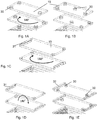
Fig. 1A : Platten mit 3 Noppen an den Rändern, Drehung in der Ebene; -
Fig. 1B : Variante - Platte mit zusätzlicher Noppe in der Mitte; -
Fig. 1C : Variante - nicht runde Noppenform, Drehung in der Ebene; -
Fig. 1D : Variante - aus der Ebene geklappte Platten, -
Fig. 1E : seitlich Randstege zur Abdichtung und -
Fig. 2 : Schnittbild eines Plattenstapels in einer Kühlvorrichtung. - Die
Figuren 1A bis 1E zeigen verschiedene Varianten der Plattenausbildung. Für einen Plattenstapel in einer Kühlvorrichtung sind mindesten drei Abstandselemente erforderlich (Fig. 1A ), damit die Platten eindeutig definiert mit vorgegebenem Abstand übereinander zu liegen kommen. Der Abstand der Platten übereinander (Schlitzweite 18 im Fenster 13 der Kühlvorrichtung) wird durch die Höhe der Abstandselemente bestimmt, was durch die Stanz- oder Prägetiefe erzielt wird. Die Abstandselemente 30, 31 sind vorzugsweise an den Seitenrändern oder in deren Nähe angeordnet, damit die Schaltgasströmung 20 möglichst wenig beeinflusst wird. Wird die Einhaltung des Plattenabstands durch eine größere Ausdehnung der Platten aufgrund von Durchbiegungen schwierig, können weitere Abstandselemente auch in größerem Abstand zu den Seitenrändern vorgesehen werden. - Die
Fig. 1A zeigt Platten mit drei Noppen 30 an den Rändern, wobei dieFig. 1B eine zweite Variante darstellt, welche einen zusätzlichen Noppen in der Mitte aufweist. - In der
Fig. 1C ist eine dritte Variante dargestellt, in der die Abstandselemente 32 eine nichtrunde Form haben. Das heißt, dass die Form der Abstandselemente nicht auf runde Elemente beschränkt ist, sondern im Prinzip beliebig sein kann. Zudem können die Elemente auch direkt an den Plattenrand gelegt sein, wie beispielhaft inFig. 1C und 1D dargestellt. DieFiguren 1A und 1C zeigen eine unsymmetrische Anordnung der Abstandselemente, so dass bei Drehung der Platten um 180° um eine Hochachse (senkrecht auf Plattenebene) die Abstandselemente zweier über einander liegender Platten nicht über einander zu liegen kommen. - In
Fig. 1D ist eine andere Art der Anordnung gezeigt. Hier wird durch Klappen um 180° der Platten um eine in der Plattenfläche liegende Achse das gewünschte Ergebnis erreicht. - Die Stanz- oder Prägetechnik kann auch zur Herstellung seitlicher Abdichtungen (Dichtelemente 32) für den durchströmten Plattenstapel verwendet werden. Dazu wird vorgeschlagen, seitlich an den Platten weitere Prägungen oder Stanzungen vorzunehmen, wie in der
Fig. 1E beispielhaft dargestellt. Im Gegensatz zu den Abstandselementen müssen die am Rand eingebrachten Prägungen oder Stanzungen zur Abdichtung ineinander greifen und sind daher symmetrisch anzuordnen. Des Weiteren ist für die Dichtwirkung hilfreich, wenn die seitlich angeordneten Prägungen tiefer ausfallen als die Höhe 18 der Abstandselemente. - Alle Kühlplatten 15 haben dieselbe Dicke 16. Vorzugsweise zwischen 500 bis 1000 µm oder für besondere Anwendungsfälle auch in einem schmaleren Bereich von 700 bis 900 µm im Mittel 800 µm
-
Figur 2 ist eine Schnittdarstellung, wobei die Kühlvorrichtung 10 senkrecht in der Mitte geschnitten ist (mit Bezugszeichen 12 als Schnittebene). Vorn in der Zeichnung befindet sich die Austrittsöffnung für die Schaltgase; der hintere Bereich der Kühlvorrichtung ist zur Schaltkammer des Installationsgeräts gerichtet. - Die Kühlplatten 15 liegen quer zur Strömungsrichtung 20 und bilden den Kühlplattenstapel. In der zeichnerisch dargestellten Ausführung nach
Fig. 2 befinden sich dreiundzwanzig Kühlplatten, die zusammen mit dem Rahmen 14 nach Masse, Volumen und Material die Wärmekapazität der Kühlvorrichtung bilden. Zwischen den Kühlplatten sind zweiundzwanzig Schlitze 17 ausgebildet. - Der Zwischenraum zwischen den Kühlplatten sind Schlitze 17. Diese haben eine Schlitzweite 18, die durch die Höhe der Abstandselemente bestimmt ist. Die Schlitzbreite 19 entspricht der Breite des Fensters in der Kühlvorrichtung. Die Höhe der Abstandselemente kann jeweils nach zu erwartenden Gasmassestrom abgestuft betragen: 100 bis 500 µm, oder 250 bis 400 µm, oder noch enger 200 bis 300 µm. Der Gesamtquerschnitt der Durchtrittsöffnungen ist im Wesentlichen bestimmt durch und abhängig von Schaltleistung bzw. Nennstrom des Installationsgeräts. Der Gesamtquerschnitt der Durchtrittsöffnungen der zeichnerisch in
Fig. 2 dargestellten Ausführung hat eine Größenordnung von 300 mm2, wenn als Schlitzweite (18) 0,2 mm, als Breite (19) 20 mm und die Anzahl der Platten mit 22 zugrunde gelegt wird. - Prinzipiell kann die Schaltgas-Kühlvorrichtung mit dem erfindungsgemäßen Plattenstapel auf alle elektromechanischen Schaltgeräte, die eine nennenswerte Ausblasung erzeugen, angewendet werden. Vorteilhaft bei Leistungsschaltern, Leitungsschutzschaltern und Motorschutzschaltern im Niederspannungsbereich.
-
- 12
- Schnittebene
- 13
- Fenster
- 14
- Rahmen
- 15
- Kühlplatte
- 16
- Plattendicke
- 17
- Schlitz
- 18
- Schlitzweite, Höhe Abstandselement
- 19
- Plattenbreite, Schlitzbreite
- 20
- Schaltgasstrom
- 30
- Abstandselement (zylindrisch)
- 31
- Abstandselement (Steg)
- 32
- Dichtelement
Claims (11)
- Plattenstapel, welcher in einer Schaltgas-Kühlvorrichtung eines elektrischen Schaltgeräts angeordnet ist, umfassend identische Platten (15) aus einem Material hoher Wärmeleitfähigkeit, welche mit einheitlichem Plattenabstand (18) gestapelt sind,
wobei die Platten jeweils mit dem Plattenabstand (18) entsprechenden Abstandselementen (30, 31) versehen sind,
wobei die Platten (15) im Stapel derart angeordnet sind, dass ihre Orientierung aufeinanderfolgend wechselt, und dadurch gekennzeichnet, dass die Abstandselemente (30, 31) als Tiefprägung in Platten aus metallischem Werkstoff ausgebildet sind. - Plattenstapel nach Anspruch 1, dadurch gekennzeichnet, dass die Platten (15) aus Stahl oder Kupfer bestehen.
- Plattenstapel nach einem der vorhergehenden Ansprüche, dadurch gekennzeichnet, dass die Abstandselemente (30) einstückig mit der Platte (15) und in ihrer Form als Noppe, als Kegel, als Kegelstumpf, als Zylinder (30) oder als Steg (31) ausgebildet sind.
- Plattenstapel nach Anspruch 3, dadurch gekennzeichnet, dass die Abstandselemente (30) nur auf einer Fläche der Platte (15) ausgebildet sind.
- Plattenstapel nach Anspruch 3, dadurch gekennzeichnet, dass die Abstandselemente (30) in einer Fläche der Platte und/oder am Rand der Platte (15) ausgebildet sind.
- Plattenstapel nach Anspruch 4 oder 5, dadurch gekennzeichnet, dass eine Anordnung der Abstandselemente (30) auf einer der Plattenflächen abweichend von einer Drehsymmetrie von 180 ° um eine auf der Plattenfläche stehende Drehachse ausgebildet ist.
- Plattenstapel nach Anspruch 4 oder 5, dadurch gekennzeichnet, dass eine Anordnung der Abstandselemente (30) auf einer der Plattenflächen abweichend von einer Drehsymmetrie von 180 ° um eine parallel zu einer Kante der Platte (15) stehende Drehachse ausgebildet ist.
- Plattenstapel nach einem der vorhergehenden Ansprüche, dadurch gekennzeichnet, dass am Rand einer Platte (15) einstückig mit der Platte Dichtelemente (32) ausgebildet sind.
- Plattenstapel nach Anspruch 8, dadurch gekennzeichnet, dass die Dichtelemente (32) als Tiefprägung ausgebildet sind.
- Plattenstapel nach Anspruch 8 oder 9, dadurch gekennzeichnet, dass die Höhe der Dichtelemente (32) größer ausgebildet ist als die Größe des Plattenabstands (18).
- Plattenstapel nach einem der vorhergehenden Ansprüche, dadurch gekennzeichnet, dass Dimensionen und Anzahl der Platten einem Fenster (13) in der Schaltgas-Kühlvorrichtung angepasst sind.
Applications Claiming Priority (2)
| Application Number | Priority Date | Filing Date | Title |
|---|---|---|---|
| US201361773289P | 2013-03-06 | 2013-03-06 | |
| PCT/EP2014/054360 WO2014135641A2 (de) | 2013-03-06 | 2014-03-06 | Plattenstapel für kühlvorrichtung in installationsgeräten |
Publications (2)
| Publication Number | Publication Date |
|---|---|
| EP2965337A2 EP2965337A2 (de) | 2016-01-13 |
| EP2965337B1 true EP2965337B1 (de) | 2017-04-19 |
Family
ID=50277201
Family Applications (1)
| Application Number | Title | Priority Date | Filing Date |
|---|---|---|---|
| EP14709914.7A Not-in-force EP2965337B1 (de) | 2013-03-06 | 2014-03-06 | Plattenstapel für kühlvorrichtung in installationsgeräten |
Country Status (4)
| Country | Link |
|---|---|
| US (1) | US9761392B2 (de) |
| EP (1) | EP2965337B1 (de) |
| CN (1) | CN105637604B (de) |
| WO (1) | WO2014135641A2 (de) |
Families Citing this family (4)
| Publication number | Priority date | Publication date | Assignee | Title |
|---|---|---|---|---|
| US20160293352A1 (en) * | 2013-11-07 | 2016-10-06 | Eaton Electrical Ip Gmbh & Co. Kg | Method for producing plate arrangements and use thereof |
| CN106796851B (zh) | 2014-11-06 | 2019-03-29 | 伊顿电气Ip两合公司 | 包括开关气体冷却组件和颗粒捕获组件的系统 |
| US10415901B2 (en) * | 2016-09-12 | 2019-09-17 | Hamilton Sundstrand Corporation | Counter-flow ceramic heat exchanger assembly and method |
| US10902728B2 (en) * | 2017-04-26 | 2021-01-26 | Ford Global Technologies, Llc | Blind spot object detection |
Family Cites Families (25)
| Publication number | Priority date | Publication date | Assignee | Title |
|---|---|---|---|---|
| US2244061A (en) * | 1940-07-31 | 1941-06-03 | Ite Circuit Breaker Ltd | Arc quencher |
| US3286065A (en) * | 1966-03-16 | 1966-11-15 | Ite Circuit Breaker Ltd | Ceramic arc plates having minimum density variations |
| US3555224A (en) * | 1968-12-23 | 1971-01-12 | Gen Electric | Arc chute for an air circuit breaker |
| US3803376A (en) * | 1972-07-27 | 1974-04-09 | Ite Imperial Corp | Vent for arc chute |
| US4019005A (en) * | 1974-12-30 | 1977-04-19 | I-T-E Imperial Corporation | Multi-pole circuit breaker with baffle shield venting |
| TW224508B (de) * | 1991-03-15 | 1994-06-01 | Toshiba Co Ltd | |
| US5589672A (en) * | 1994-06-14 | 1996-12-31 | Fuji Electric Co., Ltd. | Circuit breaker with arc quenching device and vent |
| US5628363A (en) * | 1995-04-13 | 1997-05-13 | Alliedsignal Inc. | Composite continuous sheet fin heat exchanger |
| US5655600A (en) * | 1995-06-05 | 1997-08-12 | Alliedsignal Inc. | Composite plate pin or ribbon heat exchanger |
| FR2750531B1 (fr) | 1996-06-28 | 1998-08-07 | Schneider Electric Sa | Dispositif de desionisation des gaz notamment des gaz de coupure dans une chambre d'extinction d'arc d'un disjoncteur basse tension a boitier moule et chambre d'extinction d'arc equipee de ce dispositif |
| AU724423B2 (en) * | 1997-06-09 | 2000-09-21 | Sevex North America, Inc. | Shaped multilayer metal foil shield structures and method of making |
| DE19935632A1 (de) * | 1999-07-29 | 2001-02-01 | Abb Patent Gmbh | Lichtbogenlöschblechpaket für ein elektrisches Schaltgerät |
| IT1314358B1 (it) * | 1999-12-31 | 2002-12-09 | Abb Ricerca Spa | Camera d'arco per interruttori di bassa tensione |
| ITMI20032210A1 (it) * | 2003-11-14 | 2005-05-15 | Getters Spa | Convertitore di gas di scarico di motori a combustione interna. |
| KR20060035194A (ko) * | 2004-10-21 | 2006-04-26 | 엘에스산전 주식회사 | 배선용 차단기의 소호장치 |
| US7034242B1 (en) * | 2004-11-09 | 2006-04-25 | Eaton Corporation | Arc chute and circuit interrupter employing the same |
| FR2879019B1 (fr) * | 2004-12-06 | 2008-04-04 | Schneider Electric Ind Sas | Dispositif electrique de coupure avec chambre d'extinction d'arc a ailettes de desionisation |
| US7488915B2 (en) | 2006-09-20 | 2009-02-10 | Eaton Corporation | ARC baffle, and ARC chute assembly and electrical switching apparatus employing the same |
| US7521645B2 (en) * | 2006-09-20 | 2009-04-21 | Eaton Corporation | Arc plate, and arc chute assembly and electrical switching apparatus employing the same |
| US7705263B2 (en) * | 2008-04-15 | 2010-04-27 | General Electric Company | Arc chute assembly for a circuit breaker |
| FR2931542A1 (fr) | 2008-05-22 | 2009-11-27 | Valeo Systemes Thermiques | Echangeur de chaleur a plaques, notamment pour vehicules automobiles |
| CN201293494Y (zh) * | 2008-09-03 | 2009-08-19 | 贵州贵航汽车零部件股份有限公司 | 半导体换热器 |
| DE102010034264B3 (de) | 2010-08-13 | 2012-02-23 | Abb Ag | Installationsschaltgerät mit einer Lichtbogenlöscheinrichtung |
| US8222555B2 (en) * | 2010-08-17 | 2012-07-17 | Eaton Corporation | Circuit breaker and arc chute with shield apparatus |
| JP5629558B2 (ja) | 2010-11-15 | 2014-11-19 | トヨタ自動車株式会社 | 車両用熱交換器 |
-
2014
- 2014-03-06 CN CN201480012862.4A patent/CN105637604B/zh active Active
- 2014-03-06 WO PCT/EP2014/054360 patent/WO2014135641A2/de not_active Ceased
- 2014-03-06 US US14/772,412 patent/US9761392B2/en not_active Expired - Fee Related
- 2014-03-06 EP EP14709914.7A patent/EP2965337B1/de not_active Not-in-force
Non-Patent Citations (1)
| Title |
|---|
| None * |
Also Published As
| Publication number | Publication date |
|---|---|
| US20160035517A1 (en) | 2016-02-04 |
| CN105637604A (zh) | 2016-06-01 |
| WO2014135641A2 (de) | 2014-09-12 |
| WO2014135641A3 (de) | 2016-01-14 |
| US9761392B2 (en) | 2017-09-12 |
| EP2965337A2 (de) | 2016-01-13 |
| CN105637604B (zh) | 2018-11-30 |
Similar Documents
| Publication | Publication Date | Title |
|---|---|---|
| EP2965337B1 (de) | Plattenstapel für kühlvorrichtung in installationsgeräten | |
| DE102016120841A1 (de) | Batterie mit verpresster Zellanordnung | |
| DE112009004685B4 (de) | Leiter einer elektrischen Hochspannungsvorrichtung | |
| DE2625515A1 (de) | Heizvorrichtung fuer gase oder fluessigkeiten | |
| EP3218966B1 (de) | Vorrichtung zur leistungskontaktierung | |
| DE2809070C2 (de) | Elektrischer Linearmotor | |
| EP2619770B1 (de) | Elektrischer leistungswiderstand | |
| WO2015067462A1 (de) | Herstellverfahren von plattenanordnungen und ihre verwendung | |
| EP1627441B1 (de) | Brennstoffzelle und heizeinrichtung einer brennstoffzelle | |
| EP1070248B1 (de) | Ionenmobilitätsspektrometer | |
| DE102011102257A1 (de) | Hörnerfunkenstrecke mit Deionkammer | |
| DE102013112400B4 (de) | Lichtbogenlöschkammer und Überspannungsableiter mit einer solchen | |
| EP3702219A1 (de) | Längenausgleichselement für einen stromschienenverbund, stromschienenverbund und verfahren zum herstellen eines stromschienenverbunds | |
| WO2014131619A1 (de) | Brennstoffzellenstapel | |
| DE102013201689B4 (de) | Schirmgehäuse | |
| DE102013015753B4 (de) | Zellblock für eine Batterie und Batterie | |
| DE19815436B4 (de) | Ionenmobilitätsspektrometer | |
| DE102012103559B4 (de) | Flüssigkeitsheizung | |
| WO2017178231A1 (de) | Steuerring für überspannungsableiter | |
| DE102015214126A1 (de) | Phasenleiteranordnung | |
| AT528043A1 (de) | Akkumulatorvorrichtung | |
| EP3507849A1 (de) | Batterie mit verpresster zellanordnung | |
| DE102023104603A1 (de) | Mehrzweck-Zelltrennelement für eine Batterieanordnung eines Kraftfahrzeugs, Batterieanordnung und Kraftfahrzeug | |
| DE102023201056A1 (de) | Elektrische Maschine | |
| DE102017117065A1 (de) | Thermoelektrische Baugruppe |
Legal Events
| Date | Code | Title | Description |
|---|---|---|---|
| PUAI | Public reference made under article 153(3) epc to a published international application that has entered the european phase |
Free format text: ORIGINAL CODE: 0009012 |
|
| 17P | Request for examination filed |
Effective date: 20150929 |
|
| AK | Designated contracting states |
Kind code of ref document: A2 Designated state(s): AL AT BE BG CH CY CZ DE DK EE ES FI FR GB GR HR HU IE IS IT LI LT LU LV MC MK MT NL NO PL PT RO RS SE SI SK SM TR |
|
| AX | Request for extension of the european patent |
Extension state: BA ME |
|
| R17D | Deferred search report published (corrected) |
Effective date: 20160114 |
|
| DAX | Request for extension of the european patent (deleted) | ||
| GRAP | Despatch of communication of intention to grant a patent |
Free format text: ORIGINAL CODE: EPIDOSNIGR1 |
|
| INTG | Intention to grant announced |
Effective date: 20170110 |
|
| GRAS | Grant fee paid |
Free format text: ORIGINAL CODE: EPIDOSNIGR3 |
|
| GRAA | (expected) grant |
Free format text: ORIGINAL CODE: 0009210 |
|
| AK | Designated contracting states |
Kind code of ref document: B1 Designated state(s): AL AT BE BG CH CY CZ DE DK EE ES FI FR GB GR HR HU IE IS IT LI LT LU LV MC MK MT NL NO PL PT RO RS SE SI SK SM TR |
|
| REG | Reference to a national code |
Ref country code: GB Ref legal event code: FG4D Free format text: NOT ENGLISH |
|
| REG | Reference to a national code |
Ref country code: CH Ref legal event code: EP |
|
| REG | Reference to a national code |
Ref country code: AT Ref legal event code: REF Ref document number: 886666 Country of ref document: AT Kind code of ref document: T Effective date: 20170515 |
|
| REG | Reference to a national code |
Ref country code: IE Ref legal event code: FG4D Free format text: LANGUAGE OF EP DOCUMENT: GERMAN |
|
| REG | Reference to a national code |
Ref country code: DE Ref legal event code: R096 Ref document number: 502014003480 Country of ref document: DE |
|
| REG | Reference to a national code |
Ref country code: NL Ref legal event code: MP Effective date: 20170419 |
|
| REG | Reference to a national code |
Ref country code: LT Ref legal event code: MG4D |
|
| PG25 | Lapsed in a contracting state [announced via postgrant information from national office to epo] |
Ref country code: NL Free format text: LAPSE BECAUSE OF FAILURE TO SUBMIT A TRANSLATION OF THE DESCRIPTION OR TO PAY THE FEE WITHIN THE PRESCRIBED TIME-LIMIT Effective date: 20170419 |
|
| PG25 | Lapsed in a contracting state [announced via postgrant information from national office to epo] |
Ref country code: LT Free format text: LAPSE BECAUSE OF FAILURE TO SUBMIT A TRANSLATION OF THE DESCRIPTION OR TO PAY THE FEE WITHIN THE PRESCRIBED TIME-LIMIT Effective date: 20170419 Ref country code: GR Free format text: LAPSE BECAUSE OF FAILURE TO SUBMIT A TRANSLATION OF THE DESCRIPTION OR TO PAY THE FEE WITHIN THE PRESCRIBED TIME-LIMIT Effective date: 20170720 Ref country code: FI Free format text: LAPSE BECAUSE OF FAILURE TO SUBMIT A TRANSLATION OF THE DESCRIPTION OR TO PAY THE FEE WITHIN THE PRESCRIBED TIME-LIMIT Effective date: 20170419 Ref country code: ES Free format text: LAPSE BECAUSE OF FAILURE TO SUBMIT A TRANSLATION OF THE DESCRIPTION OR TO PAY THE FEE WITHIN THE PRESCRIBED TIME-LIMIT Effective date: 20170419 Ref country code: NO Free format text: LAPSE BECAUSE OF FAILURE TO SUBMIT A TRANSLATION OF THE DESCRIPTION OR TO PAY THE FEE WITHIN THE PRESCRIBED TIME-LIMIT Effective date: 20170719 Ref country code: HR Free format text: LAPSE BECAUSE OF FAILURE TO SUBMIT A TRANSLATION OF THE DESCRIPTION OR TO PAY THE FEE WITHIN THE PRESCRIBED TIME-LIMIT Effective date: 20170419 |
|
| PG25 | Lapsed in a contracting state [announced via postgrant information from national office to epo] |
Ref country code: BG Free format text: LAPSE BECAUSE OF FAILURE TO SUBMIT A TRANSLATION OF THE DESCRIPTION OR TO PAY THE FEE WITHIN THE PRESCRIBED TIME-LIMIT Effective date: 20170719 Ref country code: PL Free format text: LAPSE BECAUSE OF FAILURE TO SUBMIT A TRANSLATION OF THE DESCRIPTION OR TO PAY THE FEE WITHIN THE PRESCRIBED TIME-LIMIT Effective date: 20170419 Ref country code: IS Free format text: LAPSE BECAUSE OF FAILURE TO SUBMIT A TRANSLATION OF THE DESCRIPTION OR TO PAY THE FEE WITHIN THE PRESCRIBED TIME-LIMIT Effective date: 20170819 Ref country code: RS Free format text: LAPSE BECAUSE OF FAILURE TO SUBMIT A TRANSLATION OF THE DESCRIPTION OR TO PAY THE FEE WITHIN THE PRESCRIBED TIME-LIMIT Effective date: 20170419 Ref country code: LV Free format text: LAPSE BECAUSE OF FAILURE TO SUBMIT A TRANSLATION OF THE DESCRIPTION OR TO PAY THE FEE WITHIN THE PRESCRIBED TIME-LIMIT Effective date: 20170419 Ref country code: SE Free format text: LAPSE BECAUSE OF FAILURE TO SUBMIT A TRANSLATION OF THE DESCRIPTION OR TO PAY THE FEE WITHIN THE PRESCRIBED TIME-LIMIT Effective date: 20170419 |
|
| REG | Reference to a national code |
Ref country code: DE Ref legal event code: R097 Ref document number: 502014003480 Country of ref document: DE |
|
| PG25 | Lapsed in a contracting state [announced via postgrant information from national office to epo] |
Ref country code: EE Free format text: LAPSE BECAUSE OF FAILURE TO SUBMIT A TRANSLATION OF THE DESCRIPTION OR TO PAY THE FEE WITHIN THE PRESCRIBED TIME-LIMIT Effective date: 20170419 Ref country code: CZ Free format text: LAPSE BECAUSE OF FAILURE TO SUBMIT A TRANSLATION OF THE DESCRIPTION OR TO PAY THE FEE WITHIN THE PRESCRIBED TIME-LIMIT Effective date: 20170419 Ref country code: DK Free format text: LAPSE BECAUSE OF FAILURE TO SUBMIT A TRANSLATION OF THE DESCRIPTION OR TO PAY THE FEE WITHIN THE PRESCRIBED TIME-LIMIT Effective date: 20170419 Ref country code: SK Free format text: LAPSE BECAUSE OF FAILURE TO SUBMIT A TRANSLATION OF THE DESCRIPTION OR TO PAY THE FEE WITHIN THE PRESCRIBED TIME-LIMIT Effective date: 20170419 Ref country code: RO Free format text: LAPSE BECAUSE OF FAILURE TO SUBMIT A TRANSLATION OF THE DESCRIPTION OR TO PAY THE FEE WITHIN THE PRESCRIBED TIME-LIMIT Effective date: 20170419 |
|
| PLBE | No opposition filed within time limit |
Free format text: ORIGINAL CODE: 0009261 |
|
| STAA | Information on the status of an ep patent application or granted ep patent |
Free format text: STATUS: NO OPPOSITION FILED WITHIN TIME LIMIT |
|
| PG25 | Lapsed in a contracting state [announced via postgrant information from national office to epo] |
Ref country code: IT Free format text: LAPSE BECAUSE OF FAILURE TO SUBMIT A TRANSLATION OF THE DESCRIPTION OR TO PAY THE FEE WITHIN THE PRESCRIBED TIME-LIMIT Effective date: 20170419 Ref country code: SM Free format text: LAPSE BECAUSE OF FAILURE TO SUBMIT A TRANSLATION OF THE DESCRIPTION OR TO PAY THE FEE WITHIN THE PRESCRIBED TIME-LIMIT Effective date: 20170419 |
|
| 26N | No opposition filed |
Effective date: 20180122 |
|
| PG25 | Lapsed in a contracting state [announced via postgrant information from national office to epo] |
Ref country code: SI Free format text: LAPSE BECAUSE OF FAILURE TO SUBMIT A TRANSLATION OF THE DESCRIPTION OR TO PAY THE FEE WITHIN THE PRESCRIBED TIME-LIMIT Effective date: 20170419 |
|
| PG25 | Lapsed in a contracting state [announced via postgrant information from national office to epo] |
Ref country code: MT Free format text: LAPSE BECAUSE OF FAILURE TO SUBMIT A TRANSLATION OF THE DESCRIPTION OR TO PAY THE FEE WITHIN THE PRESCRIBED TIME-LIMIT Effective date: 20170419 |
|
| REG | Reference to a national code |
Ref country code: CH Ref legal event code: PL |
|
| GBPC | Gb: european patent ceased through non-payment of renewal fee |
Effective date: 20180306 |
|
| PG25 | Lapsed in a contracting state [announced via postgrant information from national office to epo] |
Ref country code: MC Free format text: LAPSE BECAUSE OF FAILURE TO SUBMIT A TRANSLATION OF THE DESCRIPTION OR TO PAY THE FEE WITHIN THE PRESCRIBED TIME-LIMIT Effective date: 20170419 |
|
| REG | Reference to a national code |
Ref country code: BE Ref legal event code: MM Effective date: 20180331 |
|
| REG | Reference to a national code |
Ref country code: IE Ref legal event code: MM4A |
|
| PG25 | Lapsed in a contracting state [announced via postgrant information from national office to epo] |
Ref country code: LU Free format text: LAPSE BECAUSE OF NON-PAYMENT OF DUE FEES Effective date: 20180306 |
|
| REG | Reference to a national code |
Ref country code: DE Ref legal event code: R081 Ref document number: 502014003480 Country of ref document: DE Owner name: EATON INTELLIGENT POWER LIMITED, IE Free format text: FORMER OWNER: EATON ELECTRICAL IP GMBH & CO. KG, 12529 SCHOENEFELD, DE |
|
| PG25 | Lapsed in a contracting state [announced via postgrant information from national office to epo] |
Ref country code: IE Free format text: LAPSE BECAUSE OF NON-PAYMENT OF DUE FEES Effective date: 20180306 |
|
| PG25 | Lapsed in a contracting state [announced via postgrant information from national office to epo] |
Ref country code: BE Free format text: LAPSE BECAUSE OF NON-PAYMENT OF DUE FEES Effective date: 20180331 Ref country code: GB Free format text: LAPSE BECAUSE OF NON-PAYMENT OF DUE FEES Effective date: 20180306 Ref country code: CH Free format text: LAPSE BECAUSE OF NON-PAYMENT OF DUE FEES Effective date: 20180331 Ref country code: LI Free format text: LAPSE BECAUSE OF NON-PAYMENT OF DUE FEES Effective date: 20180331 |
|
| PG25 | Lapsed in a contracting state [announced via postgrant information from national office to epo] |
Ref country code: FR Free format text: LAPSE BECAUSE OF NON-PAYMENT OF DUE FEES Effective date: 20180331 |
|
| PG25 | Lapsed in a contracting state [announced via postgrant information from national office to epo] |
Ref country code: TR Free format text: LAPSE BECAUSE OF FAILURE TO SUBMIT A TRANSLATION OF THE DESCRIPTION OR TO PAY THE FEE WITHIN THE PRESCRIBED TIME-LIMIT Effective date: 20170419 |
|
| PG25 | Lapsed in a contracting state [announced via postgrant information from national office to epo] |
Ref country code: PT Free format text: LAPSE BECAUSE OF FAILURE TO SUBMIT A TRANSLATION OF THE DESCRIPTION OR TO PAY THE FEE WITHIN THE PRESCRIBED TIME-LIMIT Effective date: 20170419 |
|
| PG25 | Lapsed in a contracting state [announced via postgrant information from national office to epo] |
Ref country code: HU Free format text: LAPSE BECAUSE OF FAILURE TO SUBMIT A TRANSLATION OF THE DESCRIPTION OR TO PAY THE FEE WITHIN THE PRESCRIBED TIME-LIMIT; INVALID AB INITIO Effective date: 20140306 Ref country code: MK Free format text: LAPSE BECAUSE OF NON-PAYMENT OF DUE FEES Effective date: 20170419 Ref country code: CY Free format text: LAPSE BECAUSE OF FAILURE TO SUBMIT A TRANSLATION OF THE DESCRIPTION OR TO PAY THE FEE WITHIN THE PRESCRIBED TIME-LIMIT Effective date: 20170419 |
|
| PG25 | Lapsed in a contracting state [announced via postgrant information from national office to epo] |
Ref country code: AL Free format text: LAPSE BECAUSE OF FAILURE TO SUBMIT A TRANSLATION OF THE DESCRIPTION OR TO PAY THE FEE WITHIN THE PRESCRIBED TIME-LIMIT Effective date: 20170419 |
|
| REG | Reference to a national code |
Ref country code: AT Ref legal event code: MM01 Ref document number: 886666 Country of ref document: AT Kind code of ref document: T Effective date: 20190306 |
|
| PG25 | Lapsed in a contracting state [announced via postgrant information from national office to epo] |
Ref country code: AT Free format text: LAPSE BECAUSE OF NON-PAYMENT OF DUE FEES Effective date: 20190306 |
|
| P01 | Opt-out of the competence of the unified patent court (upc) registered |
Effective date: 20230521 |
|
| PGFP | Annual fee paid to national office [announced via postgrant information from national office to epo] |
Ref country code: DE Payment date: 20240220 Year of fee payment: 11 |
|
| REG | Reference to a national code |
Ref country code: DE Ref legal event code: R119 Ref document number: 502014003480 Country of ref document: DE |