EP2965337B1 - Pile de plaques pour un dispositif de refroidissement dans des appareils d'installation - Google Patents
Pile de plaques pour un dispositif de refroidissement dans des appareils d'installation Download PDFInfo
- Publication number
- EP2965337B1 EP2965337B1 EP14709914.7A EP14709914A EP2965337B1 EP 2965337 B1 EP2965337 B1 EP 2965337B1 EP 14709914 A EP14709914 A EP 14709914A EP 2965337 B1 EP2965337 B1 EP 2965337B1
- Authority
- EP
- European Patent Office
- Prior art keywords
- plate
- plates
- spacer elements
- stack according
- plate stack
- Prior art date
- Legal status (The legal status is an assumption and is not a legal conclusion. Google has not performed a legal analysis and makes no representation as to the accuracy of the status listed.)
- Active
Links
- 238000001816 cooling Methods 0.000 title claims description 35
- 238000009434 installation Methods 0.000 title description 6
- 125000006850 spacer group Chemical group 0.000 claims description 39
- 238000007789 sealing Methods 0.000 claims description 12
- 239000000463 material Substances 0.000 claims description 6
- RYGMFSIKBFXOCR-UHFFFAOYSA-N Copper Chemical compound [Cu] RYGMFSIKBFXOCR-UHFFFAOYSA-N 0.000 claims description 2
- 229910000831 Steel Inorganic materials 0.000 claims description 2
- 229910052802 copper Inorganic materials 0.000 claims description 2
- 239000010949 copper Substances 0.000 claims description 2
- 239000007769 metal material Substances 0.000 claims description 2
- 239000010959 steel Substances 0.000 claims description 2
- 239000007789 gas Substances 0.000 description 9
- 238000004049 embossing Methods 0.000 description 4
- 238000000034 method Methods 0.000 description 3
- 239000000919 ceramic Substances 0.000 description 2
- 230000001419 dependent effect Effects 0.000 description 2
- 230000000694 effects Effects 0.000 description 2
- 238000004519 manufacturing process Methods 0.000 description 2
- 238000004080 punching Methods 0.000 description 2
- 206010000496 acne Diseases 0.000 description 1
- 230000009286 beneficial effect Effects 0.000 description 1
- 238000010276 construction Methods 0.000 description 1
- 238000005520 cutting process Methods 0.000 description 1
- 238000004870 electrical engineering Methods 0.000 description 1
- 238000010616 electrical installation Methods 0.000 description 1
- 238000003780 insertion Methods 0.000 description 1
- 230000037431 insertion Effects 0.000 description 1
- 238000009413 insulation Methods 0.000 description 1
- 239000002245 particle Substances 0.000 description 1
- 238000010791 quenching Methods 0.000 description 1
- 230000000171 quenching effect Effects 0.000 description 1
Images

Classifications
-
- H—ELECTRICITY
- H01—ELECTRIC ELEMENTS
- H01H—ELECTRIC SWITCHES; RELAYS; SELECTORS; EMERGENCY PROTECTIVE DEVICES
- H01H33/00—High-tension or heavy-current switches with arc-extinguishing or arc-preventing means
- H01H33/02—Details
- H01H33/04—Means for extinguishing or preventing arc between current-carrying parts
- H01H33/08—Stationary parts for restricting or subdividing the arc, e.g. barrier plate
- H01H33/10—Metal parts
-
- H—ELECTRICITY
- H01—ELECTRIC ELEMENTS
- H01H—ELECTRIC SWITCHES; RELAYS; SELECTORS; EMERGENCY PROTECTIVE DEVICES
- H01H9/00—Details of switching devices, not covered by groups H01H1/00 - H01H7/00
- H01H9/30—Means for extinguishing or preventing arc between current-carrying parts
- H01H9/34—Stationary parts for restricting or subdividing the arc, e.g. barrier plate
- H01H9/342—Venting arrangements for arc chutes
-
- H—ELECTRICITY
- H01—ELECTRIC ELEMENTS
- H01H—ELECTRIC SWITCHES; RELAYS; SELECTORS; EMERGENCY PROTECTIVE DEVICES
- H01H50/00—Details of electromagnetic relays
- H01H50/12—Ventilating; Cooling; Heating
-
- H—ELECTRICITY
- H01—ELECTRIC ELEMENTS
- H01H—ELECTRIC SWITCHES; RELAYS; SELECTORS; EMERGENCY PROTECTIVE DEVICES
- H01H9/00—Details of switching devices, not covered by groups H01H1/00 - H01H7/00
- H01H9/30—Means for extinguishing or preventing arc between current-carrying parts
- H01H9/34—Stationary parts for restricting or subdividing the arc, e.g. barrier plate
- H01H9/36—Metal parts
-
- H—ELECTRICITY
- H01—ELECTRIC ELEMENTS
- H01H—ELECTRIC SWITCHES; RELAYS; SELECTORS; EMERGENCY PROTECTIVE DEVICES
- H01H9/00—Details of switching devices, not covered by groups H01H1/00 - H01H7/00
- H01H9/52—Cooling of switch parts
Definitions
- the invention relates to a plate stack for a cooling device in an electrical installation device.
- splitting plates In electrical engineering, parallel plate arrangements with a defined spacing are typically known as splitter stacks.
- the plates i.a. Fixed on special side walls or enclosures and kept at a distance and also at the same time electrically insulated against each other.
- EP 1 667 180 A1 discloses a plate stack, which is arranged in a switching gas cooling device of an electrical switching device, according to the preamble of claim 1. It is the object of the invention to provide cooling plates in a device to installation equipment for cooling of exhaust gases, which are designed uniformly and with tight defined distance can be stacked.
- the plate stack consists of identical plates made of a material of high thermal conductivity, wherein the plates are each provided with the plate spacing corresponding spacers, and wherein the plates are arranged in the stack so that their orientation changes sequentially.
- the plate stack is arranged in a switching gas cooling device of an installation device.
- spacer elements are provided on the plates, said plate and spacers are integrally formed.
- a raised spacer element is created as a bulge by plastic deformation on one side and a depression on the opposite side.
- the invention assumes that the deep stamping process is performed on only one side of the material, so that bulges only occur on one side of the materials. If the plates were stacked in identical orientation, the raised embossments of one plate would dip into the recesses of the next plate.
- cooling plates made of highly thermally conductive ceramics, in which, however, only spacer elements and on the opposite side no depressions are formed.
- the description of the invention therefore relates primarily to metallic cooling plates.
- the parallel cooling plates are arranged at a close distance in the tenth of a millimeter range. Compliance with this narrow distance is essential to the function crucial for cooling and pressure gradient. Therefore, in the arrangement and fixation of the cooling plates, a design is chosen that allows tight tolerances and is suitable for mass production. Furthermore, the parallel-lying cooling plates should be constructed so that a sufficient seal against currents is present, so that possible no exhaust gases to the cooling device passed uncooled the switching device.
- the plate stack arrangement according to the invention is designed such that position and dimension are designed to be insensitive to tolerances. It is advantageous that a mutual insulation of the plates is not needed.
- the spacer elements produced by deep stamping can actually serve as spacers, the arrangement of the spacer elements of successive plates must be made different. This could be achieved in principle by at least two different plate designs with different arrangement of the spacer elements. According to the invention, however, only an identical embodiment is used, wherein the plates are arranged in the stack so that their orientation changes sequentially.
- the change in orientation in the plate stack can take place in that successive plates are each rotated in a plane parallel to the plate surface by 180 ° to each other or arranged folded around an edge of the plates by 180 °. This is made possible by an asymmetrical arrangement of the spacer elements on the plates (rotational asymmetry with respect to 180 °).
- the plates usually have a rectangular format. In the case in which the plates are formed square, there is correspondingly another consideration of Drehunsymmetrie, or the arrangement of the spacer elements.
- the plate stack is part of a cooling device and requires for its function both a holding device (frame / housing), which holds the plates together, as well as an adequate seal against lateral, the plate stack passing flows.
- the plates may preferably be formed such that a window formed in the cooling device is designed to be smooth on the inside as a frame for the stack of plates - ie without insertion grooves.
- An inventively designed plate stack forms by itself a good cohesion and provides the necessary seal against a smooth inner wall of the window.
- the plates can be made of steel, copper or highly thermally conductive ceramics.
- the spacer elements are formed as a deep embossing.
- the spacers are integral with the plate and formed in shape as a knob, as a cone, as a truncated cone, as a cylinder or as a web.
- the spacers should be formed only on one surface of a plate.
- the spacers may be formed in the surface of the plate and / or on the edge of the plate.
- At the edge of a plate can be integrally formed with the plate sealing elements.
- the height of the sealing elements should be made larger than the size of the plate spacing.
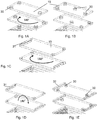
- the Figures 1A to 1E show different variants of plate training. At least three spacers are required for a stack of plates in a cooling device ( Fig. 1A ) so that the plates are clearly defined one above the other at a predetermined distance.
- the distance of the plates one above the other is determined by the height of the spacer elements, which is achieved by the punching or embossing depth.
- the spacer elements 30, 31 are preferably arranged on the side edges or in their vicinity, so that the switching gas flow 20 is influenced as little as possible. If compliance with the plate spacing becomes difficult due to greater expansion of the plates due to deflections, additional spacer elements can also be provided at a greater distance from the side edges.
- the Fig. 1A shows plates with three nubs 30 at the edges
- the Fig. 1B represents a second variant, which has an additional nubs in the middle.
- FIG. 1C a third variant is shown, in which the spacer elements 32 have a non-circular shape.
- shape of the spacer elements is not limited to round elements, but in principle may be arbitrary.
- the elements can also be placed directly on the plate edge, as exemplified in Figs. 1C and 1D shown.
- the FIGS. 1A and 1C show an asymmetrical arrangement of the spacer elements, so that when rotating the plates by 180 ° about a vertical axis (perpendicular to the plate plane), the spacer elements of two superimposed plates do not come to lie over each other.
- Fig. 1D is shown a different type of arrangement.
- the desired result is achieved by folding through 180 ° of the plates about an axis lying in the plate surface.
- the stamping or embossing technique can also be used for the production of lateral seals (sealing elements 32) for the flow-through plate stack.
- lateral seals sealing elements 32
- the impressions or punches introduced at the edge must mesh with each other for sealing purposes and must therefore be arranged symmetrically.
- All cooling plates 15 have the same thickness 16. Preferably between 500 to 1000 microns or for special applications, even in a narrower range of 700 to 900 microns on average 800 microns
- FIG. 2 is a sectional view, wherein the cooling device 10 is cut perpendicularly in the middle (with reference numeral 12 as a sectional plane).
- the cooling device 10 is cut perpendicularly in the middle (with reference numeral 12 as a sectional plane).
- reference numeral 12 As a sectional plane.
- the cooling plates 15 are transverse to the flow direction 20 and form the cold plate stack.
- the cooling plates 15 are transverse to the flow direction 20 and form the cold plate stack.
- Twenty-two slots 17 are formed between the cooling plates.
- the space between the cooling plates are slots 17. These have a slot width 18, which is determined by the height of the spacers.
- the slot width 19 corresponds to the width of the window in the cooling device.
- the height of the spacer elements can each be graded according to expected gas mass flow: 100 to 500 microns, or 250 to 400 microns, or even narrower 200 to 300 microns.
- the total cross section of the passage openings is essentially determined by and dependent on the switching power or rated current of the installation device.
- the total cross section of the passage openings of the drawing in Fig. 2 has an order of magnitude of 300 mm 2 , if the slot width (18) is 0.2 mm, the width (19) is 20 mm and the number of plates is 22.
- the switching gas cooling device with the plate stack according to the invention can be applied to all electromechanical switching devices which produce a significant blow-out.
Landscapes
- Heat-Exchange Devices With Radiators And Conduit Assemblies (AREA)
- Cooling Or The Like Of Electrical Apparatus (AREA)
Claims (11)
- Pile de plaques, qui est disposée dans un dispositif de refroidissement à gaz de commutation d'un appareil de commutation électrique, comprenant des plaques (15) identiques composées d'un matériau à conductivité thermique élevée, lesquelles sont empilées avec un espacement entre les plaques (18) homogène,
dans laquelle les plaques sont pourvues respectivement d'éléments d'espacement (30, 31) correspondant à l'espacement entre les plaques (18),
dans laquelle les plaques (15) sont disposées dans la pile de telle manière que leur orientation alterne de manière successive, et
caractérisée en ce que
les éléments d'espacement (30, 31) sont réalisés à partir d'un matériau métallique sous la forme d'un estampage profond dans des plaques. - Pile de plaques selon la revendication 1, caractérisée en ce que les plaques (15) sont constituées d'acier ou de cuivre.
- Pile de plaques selon l'une quelconque des revendications précédentes, caractérisée en ce que les éléments d'espacement (30) sont réalisés d'un seul tenant avec la plaque (15) et, dans leur forme, sous la forme d'une protubérance, d'un cône, d'un cône tronqué, d'un cylindre (30) ou d'une entretoise (31).
- Pile de plaques selon la revendication 3, caractérisée en ce que les éléments d'espacement (30) sont réalisés seulement sur une surface de la plaque (15).
- Pile de plaques selon la revendication 3, caractérisée en ce que les éléments d'espacement (30) sont réalisés dans une surface de la plaque et/ou au niveau du bord de la plaque (15).
- Pile de plaques selon la revendication 4 ou 5, caractérisée en ce qu'un ensemble des éléments d'espacement (30) est réalisé sur une des surfaces de plaque en s'écartant d'une symétrie en rotation de 180° autour d'un axe de rotation situé sur la surface de plaque.
- Pile de plaques selon la revendication 4 ou 5, caractérisée en ce qu'un ensemble des éléments d'espacement (30) est réalisé sur une des surfaces de plaque en s'écartant d'une symétrie de rotation de 180° autour d'un axe de rotation situé de manière parallèle par rapport à une arête de la plaque (15).
- Pile de plaques selon l'une quelconque des revendications précédentes, caractérisée en ce que des éléments d'étanchéité (32) sont réalisés au niveau du bord d'une plaque (15) d'un seul tenant avec la plaque.
- Pile de plaques selon la revendication 8, caractérisée en ce que les éléments d'étanchéité (32) sont réalisés sous la forme d'un emboutissage profond.
- Pile de plaques selon la revendication 8 ou 9, caractérisée en ce que la hauteur des éléments d'étanchéité (32) est réalisée plus grande que la grandeur de l'espacement entre les plaques (18).
- Pile de plaques selon l'une quelconque des revendications précédentes, caractérisée en ce que les dimensions et le nombre des plaques sont adaptés à une fenêtre (13) dans le dispositif de refroidissement à gaz de commutation.
Applications Claiming Priority (2)
| Application Number | Priority Date | Filing Date | Title |
|---|---|---|---|
| US201361773289P | 2013-03-06 | 2013-03-06 | |
| PCT/EP2014/054360 WO2014135641A2 (fr) | 2013-03-06 | 2014-03-06 | Pile de plaques pour un dispositif de refroidissement dans des appareils d'installation |
Publications (2)
| Publication Number | Publication Date |
|---|---|
| EP2965337A2 EP2965337A2 (fr) | 2016-01-13 |
| EP2965337B1 true EP2965337B1 (fr) | 2017-04-19 |
Family
ID=50277201
Family Applications (1)
| Application Number | Title | Priority Date | Filing Date |
|---|---|---|---|
| EP14709914.7A Active EP2965337B1 (fr) | 2013-03-06 | 2014-03-06 | Pile de plaques pour un dispositif de refroidissement dans des appareils d'installation |
Country Status (4)
| Country | Link |
|---|---|
| US (1) | US9761392B2 (fr) |
| EP (1) | EP2965337B1 (fr) |
| CN (1) | CN105637604B (fr) |
| WO (1) | WO2014135641A2 (fr) |
Families Citing this family (4)
| Publication number | Priority date | Publication date | Assignee | Title |
|---|---|---|---|---|
| CN105684117B (zh) * | 2013-11-07 | 2018-05-04 | 伊顿电气Ip两合公司 | 制造板装置的方法及其应用 |
| US10079121B2 (en) | 2014-11-06 | 2018-09-18 | Eaton Intelligent Power Limited | Switching gas cooling and particle trapping system |
| US10415901B2 (en) * | 2016-09-12 | 2019-09-17 | Hamilton Sundstrand Corporation | Counter-flow ceramic heat exchanger assembly and method |
| US10902728B2 (en) * | 2017-04-26 | 2021-01-26 | Ford Global Technologies, Llc | Blind spot object detection |
Family Cites Families (25)
| Publication number | Priority date | Publication date | Assignee | Title |
|---|---|---|---|---|
| US2244061A (en) * | 1940-07-31 | 1941-06-03 | Ite Circuit Breaker Ltd | Arc quencher |
| US3286065A (en) * | 1966-03-16 | 1966-11-15 | Ite Circuit Breaker Ltd | Ceramic arc plates having minimum density variations |
| US3555224A (en) * | 1968-12-23 | 1971-01-12 | Gen Electric | Arc chute for an air circuit breaker |
| US3803376A (en) * | 1972-07-27 | 1974-04-09 | Ite Imperial Corp | Vent for arc chute |
| US4019005A (en) * | 1974-12-30 | 1977-04-19 | I-T-E Imperial Corporation | Multi-pole circuit breaker with baffle shield venting |
| TW224508B (fr) * | 1991-03-15 | 1994-06-01 | Toshiba Co Ltd | |
| US5589672A (en) * | 1994-06-14 | 1996-12-31 | Fuji Electric Co., Ltd. | Circuit breaker with arc quenching device and vent |
| US5628363A (en) * | 1995-04-13 | 1997-05-13 | Alliedsignal Inc. | Composite continuous sheet fin heat exchanger |
| US5655600A (en) * | 1995-06-05 | 1997-08-12 | Alliedsignal Inc. | Composite plate pin or ribbon heat exchanger |
| FR2750531B1 (fr) | 1996-06-28 | 1998-08-07 | Schneider Electric Sa | Dispositif de desionisation des gaz notamment des gaz de coupure dans une chambre d'extinction d'arc d'un disjoncteur basse tension a boitier moule et chambre d'extinction d'arc equipee de ce dispositif |
| WO1998056573A1 (fr) * | 1997-06-09 | 1998-12-17 | Atd Corporation | Structures multifeuilles de toles forgees/matricees de blindage, et leur procede de fabrication |
| DE19935632A1 (de) * | 1999-07-29 | 2001-02-01 | Abb Patent Gmbh | Lichtbogenlöschblechpaket für ein elektrisches Schaltgerät |
| IT1314358B1 (it) * | 1999-12-31 | 2002-12-09 | Abb Ricerca Spa | Camera d'arco per interruttori di bassa tensione |
| ITMI20032210A1 (it) * | 2003-11-14 | 2005-05-15 | Getters Spa | Convertitore di gas di scarico di motori a combustione interna. |
| KR20060035194A (ko) * | 2004-10-21 | 2006-04-26 | 엘에스산전 주식회사 | 배선용 차단기의 소호장치 |
| US7034242B1 (en) * | 2004-11-09 | 2006-04-25 | Eaton Corporation | Arc chute and circuit interrupter employing the same |
| FR2879019B1 (fr) * | 2004-12-06 | 2008-04-04 | Schneider Electric Ind Sas | Dispositif electrique de coupure avec chambre d'extinction d'arc a ailettes de desionisation |
| US7521645B2 (en) * | 2006-09-20 | 2009-04-21 | Eaton Corporation | Arc plate, and arc chute assembly and electrical switching apparatus employing the same |
| US7488915B2 (en) | 2006-09-20 | 2009-02-10 | Eaton Corporation | ARC baffle, and ARC chute assembly and electrical switching apparatus employing the same |
| US7705263B2 (en) * | 2008-04-15 | 2010-04-27 | General Electric Company | Arc chute assembly for a circuit breaker |
| FR2931542A1 (fr) * | 2008-05-22 | 2009-11-27 | Valeo Systemes Thermiques | Echangeur de chaleur a plaques, notamment pour vehicules automobiles |
| CN201293494Y (zh) * | 2008-09-03 | 2009-08-19 | 贵州贵航汽车零部件股份有限公司 | 半导体换热器 |
| DE102010034264B3 (de) | 2010-08-13 | 2012-02-23 | Abb Ag | Installationsschaltgerät mit einer Lichtbogenlöscheinrichtung |
| US8222555B2 (en) * | 2010-08-17 | 2012-07-17 | Eaton Corporation | Circuit breaker and arc chute with shield apparatus |
| JP5629558B2 (ja) | 2010-11-15 | 2014-11-19 | トヨタ自動車株式会社 | 車両用熱交換器 |
-
2014
- 2014-03-06 WO PCT/EP2014/054360 patent/WO2014135641A2/fr active Application Filing
- 2014-03-06 CN CN201480012862.4A patent/CN105637604B/zh active Active
- 2014-03-06 US US14/772,412 patent/US9761392B2/en active Active
- 2014-03-06 EP EP14709914.7A patent/EP2965337B1/fr active Active
Non-Patent Citations (1)
| Title |
|---|
| None * |
Also Published As
| Publication number | Publication date |
|---|---|
| US9761392B2 (en) | 2017-09-12 |
| US20160035517A1 (en) | 2016-02-04 |
| WO2014135641A3 (fr) | 2016-01-14 |
| EP2965337A2 (fr) | 2016-01-13 |
| WO2014135641A2 (fr) | 2014-09-12 |
| CN105637604B (zh) | 2018-11-30 |
| CN105637604A (zh) | 2016-06-01 |
Similar Documents
| Publication | Publication Date | Title |
|---|---|---|
| DE602005003908T2 (de) | Lichtbogenkammer und elektromagnetischer Schalter mit solchen Lichtbogenkammer | |
| EP2965337B1 (fr) | Pile de plaques pour un dispositif de refroidissement dans des appareils d'installation | |
| DE2625515A1 (de) | Heizvorrichtung fuer gase oder fluessigkeiten | |
| DE102016120841A1 (de) | Batterie mit verpresster Zellanordnung | |
| WO2011051386A1 (fr) | Agencement d'élément de batterie | |
| EP3218966B1 (fr) | Agencement pour connection de puissance | |
| EP3079442A1 (fr) | Dispositif de chauffage electrique et cadre associe | |
| WO2015067462A1 (fr) | Procédé de fabrication d'ensembles de plaques et utilisation de ces ensembles | |
| EP2619770B1 (fr) | Résistance de puissance électrique | |
| DE112009004685B4 (de) | Leiter einer elektrischen Hochspannungsvorrichtung | |
| DE102018129226A1 (de) | Elektrische Maschine mit mehreren als Hohlleiter ausgebildeten starren Wicklungsstücken - elektrisches Anschlusskonzept | |
| EP1627441B1 (fr) | Pile a combustible et systeme de chauffage de pile a combustible | |
| EP1070248B1 (fr) | Spectrometre de mobilite ionique | |
| EP3716381B1 (fr) | Plaque bipolaire destinée à l'utilisation dans une empilement de piles à combustible | |
| EP3476000B1 (fr) | Dispositif de conversion d'énergie, en particulier pile à combustible ou électrolyseur | |
| DE102011102257A1 (de) | Hörnerfunkenstrecke mit Deionkammer | |
| EP3702219A1 (fr) | Élément de compensation de la longueur pour un ensemble de rails conducteurs, ensemble de rails conducteurs et procédé de fabrication d'un ensemble de rails conducteurs | |
| EP1467597B1 (fr) | Dispositif de chauffage | |
| DE102015214126A1 (de) | Phasenleiteranordnung | |
| DE19815436B4 (de) | Ionenmobilitätsspektrometer | |
| EP1999829B1 (fr) | Paroi de séparation d'une armoire de distribution | |
| WO2014131619A1 (fr) | Empilement de piles à combustible | |
| EP3507849B1 (fr) | Batterie comprenant un ensemble d'éléments comprimés | |
| WO2017178231A1 (fr) | Anneau de garde pour dispositif de protection contre les surtensions | |
| DE102017117065A1 (de) | Thermoelektrische Baugruppe |
Legal Events
| Date | Code | Title | Description |
|---|---|---|---|
| PUAI | Public reference made under article 153(3) epc to a published international application that has entered the european phase |
Free format text: ORIGINAL CODE: 0009012 |
|
| 17P | Request for examination filed |
Effective date: 20150929 |
|
| AK | Designated contracting states |
Kind code of ref document: A2 Designated state(s): AL AT BE BG CH CY CZ DE DK EE ES FI FR GB GR HR HU IE IS IT LI LT LU LV MC MK MT NL NO PL PT RO RS SE SI SK SM TR |
|
| AX | Request for extension of the european patent |
Extension state: BA ME |
|
| R17D | Deferred search report published (corrected) |
Effective date: 20160114 |
|
| DAX | Request for extension of the european patent (deleted) | ||
| GRAP | Despatch of communication of intention to grant a patent |
Free format text: ORIGINAL CODE: EPIDOSNIGR1 |
|
| INTG | Intention to grant announced |
Effective date: 20170110 |
|
| GRAS | Grant fee paid |
Free format text: ORIGINAL CODE: EPIDOSNIGR3 |
|
| GRAA | (expected) grant |
Free format text: ORIGINAL CODE: 0009210 |
|
| AK | Designated contracting states |
Kind code of ref document: B1 Designated state(s): AL AT BE BG CH CY CZ DE DK EE ES FI FR GB GR HR HU IE IS IT LI LT LU LV MC MK MT NL NO PL PT RO RS SE SI SK SM TR |
|
| REG | Reference to a national code |
Ref country code: GB Ref legal event code: FG4D Free format text: NOT ENGLISH |
|
| REG | Reference to a national code |
Ref country code: CH Ref legal event code: EP |
|
| REG | Reference to a national code |
Ref country code: AT Ref legal event code: REF Ref document number: 886666 Country of ref document: AT Kind code of ref document: T Effective date: 20170515 |
|
| REG | Reference to a national code |
Ref country code: IE Ref legal event code: FG4D Free format text: LANGUAGE OF EP DOCUMENT: GERMAN |
|
| REG | Reference to a national code |
Ref country code: DE Ref legal event code: R096 Ref document number: 502014003480 Country of ref document: DE |
|
| REG | Reference to a national code |
Ref country code: NL Ref legal event code: MP Effective date: 20170419 |
|
| REG | Reference to a national code |
Ref country code: LT Ref legal event code: MG4D |
|
| PG25 | Lapsed in a contracting state [announced via postgrant information from national office to epo] |
Ref country code: NL Free format text: LAPSE BECAUSE OF FAILURE TO SUBMIT A TRANSLATION OF THE DESCRIPTION OR TO PAY THE FEE WITHIN THE PRESCRIBED TIME-LIMIT Effective date: 20170419 |
|
| PG25 | Lapsed in a contracting state [announced via postgrant information from national office to epo] |
Ref country code: LT Free format text: LAPSE BECAUSE OF FAILURE TO SUBMIT A TRANSLATION OF THE DESCRIPTION OR TO PAY THE FEE WITHIN THE PRESCRIBED TIME-LIMIT Effective date: 20170419 Ref country code: GR Free format text: LAPSE BECAUSE OF FAILURE TO SUBMIT A TRANSLATION OF THE DESCRIPTION OR TO PAY THE FEE WITHIN THE PRESCRIBED TIME-LIMIT Effective date: 20170720 Ref country code: FI Free format text: LAPSE BECAUSE OF FAILURE TO SUBMIT A TRANSLATION OF THE DESCRIPTION OR TO PAY THE FEE WITHIN THE PRESCRIBED TIME-LIMIT Effective date: 20170419 Ref country code: ES Free format text: LAPSE BECAUSE OF FAILURE TO SUBMIT A TRANSLATION OF THE DESCRIPTION OR TO PAY THE FEE WITHIN THE PRESCRIBED TIME-LIMIT Effective date: 20170419 Ref country code: NO Free format text: LAPSE BECAUSE OF FAILURE TO SUBMIT A TRANSLATION OF THE DESCRIPTION OR TO PAY THE FEE WITHIN THE PRESCRIBED TIME-LIMIT Effective date: 20170719 Ref country code: HR Free format text: LAPSE BECAUSE OF FAILURE TO SUBMIT A TRANSLATION OF THE DESCRIPTION OR TO PAY THE FEE WITHIN THE PRESCRIBED TIME-LIMIT Effective date: 20170419 |
|
| PG25 | Lapsed in a contracting state [announced via postgrant information from national office to epo] |
Ref country code: BG Free format text: LAPSE BECAUSE OF FAILURE TO SUBMIT A TRANSLATION OF THE DESCRIPTION OR TO PAY THE FEE WITHIN THE PRESCRIBED TIME-LIMIT Effective date: 20170719 Ref country code: PL Free format text: LAPSE BECAUSE OF FAILURE TO SUBMIT A TRANSLATION OF THE DESCRIPTION OR TO PAY THE FEE WITHIN THE PRESCRIBED TIME-LIMIT Effective date: 20170419 Ref country code: IS Free format text: LAPSE BECAUSE OF FAILURE TO SUBMIT A TRANSLATION OF THE DESCRIPTION OR TO PAY THE FEE WITHIN THE PRESCRIBED TIME-LIMIT Effective date: 20170819 Ref country code: RS Free format text: LAPSE BECAUSE OF FAILURE TO SUBMIT A TRANSLATION OF THE DESCRIPTION OR TO PAY THE FEE WITHIN THE PRESCRIBED TIME-LIMIT Effective date: 20170419 Ref country code: LV Free format text: LAPSE BECAUSE OF FAILURE TO SUBMIT A TRANSLATION OF THE DESCRIPTION OR TO PAY THE FEE WITHIN THE PRESCRIBED TIME-LIMIT Effective date: 20170419 Ref country code: SE Free format text: LAPSE BECAUSE OF FAILURE TO SUBMIT A TRANSLATION OF THE DESCRIPTION OR TO PAY THE FEE WITHIN THE PRESCRIBED TIME-LIMIT Effective date: 20170419 |
|
| REG | Reference to a national code |
Ref country code: DE Ref legal event code: R097 Ref document number: 502014003480 Country of ref document: DE |
|
| PG25 | Lapsed in a contracting state [announced via postgrant information from national office to epo] |
Ref country code: EE Free format text: LAPSE BECAUSE OF FAILURE TO SUBMIT A TRANSLATION OF THE DESCRIPTION OR TO PAY THE FEE WITHIN THE PRESCRIBED TIME-LIMIT Effective date: 20170419 Ref country code: CZ Free format text: LAPSE BECAUSE OF FAILURE TO SUBMIT A TRANSLATION OF THE DESCRIPTION OR TO PAY THE FEE WITHIN THE PRESCRIBED TIME-LIMIT Effective date: 20170419 Ref country code: DK Free format text: LAPSE BECAUSE OF FAILURE TO SUBMIT A TRANSLATION OF THE DESCRIPTION OR TO PAY THE FEE WITHIN THE PRESCRIBED TIME-LIMIT Effective date: 20170419 Ref country code: SK Free format text: LAPSE BECAUSE OF FAILURE TO SUBMIT A TRANSLATION OF THE DESCRIPTION OR TO PAY THE FEE WITHIN THE PRESCRIBED TIME-LIMIT Effective date: 20170419 Ref country code: RO Free format text: LAPSE BECAUSE OF FAILURE TO SUBMIT A TRANSLATION OF THE DESCRIPTION OR TO PAY THE FEE WITHIN THE PRESCRIBED TIME-LIMIT Effective date: 20170419 |
|
| PLBE | No opposition filed within time limit |
Free format text: ORIGINAL CODE: 0009261 |
|
| STAA | Information on the status of an ep patent application or granted ep patent |
Free format text: STATUS: NO OPPOSITION FILED WITHIN TIME LIMIT |
|
| PG25 | Lapsed in a contracting state [announced via postgrant information from national office to epo] |
Ref country code: IT Free format text: LAPSE BECAUSE OF FAILURE TO SUBMIT A TRANSLATION OF THE DESCRIPTION OR TO PAY THE FEE WITHIN THE PRESCRIBED TIME-LIMIT Effective date: 20170419 Ref country code: SM Free format text: LAPSE BECAUSE OF FAILURE TO SUBMIT A TRANSLATION OF THE DESCRIPTION OR TO PAY THE FEE WITHIN THE PRESCRIBED TIME-LIMIT Effective date: 20170419 |
|
| 26N | No opposition filed |
Effective date: 20180122 |
|
| PG25 | Lapsed in a contracting state [announced via postgrant information from national office to epo] |
Ref country code: SI Free format text: LAPSE BECAUSE OF FAILURE TO SUBMIT A TRANSLATION OF THE DESCRIPTION OR TO PAY THE FEE WITHIN THE PRESCRIBED TIME-LIMIT Effective date: 20170419 |
|
| PG25 | Lapsed in a contracting state [announced via postgrant information from national office to epo] |
Ref country code: MT Free format text: LAPSE BECAUSE OF FAILURE TO SUBMIT A TRANSLATION OF THE DESCRIPTION OR TO PAY THE FEE WITHIN THE PRESCRIBED TIME-LIMIT Effective date: 20170419 |
|
| REG | Reference to a national code |
Ref country code: CH Ref legal event code: PL |
|
| GBPC | Gb: european patent ceased through non-payment of renewal fee |
Effective date: 20180306 |
|
| PG25 | Lapsed in a contracting state [announced via postgrant information from national office to epo] |
Ref country code: MC Free format text: LAPSE BECAUSE OF FAILURE TO SUBMIT A TRANSLATION OF THE DESCRIPTION OR TO PAY THE FEE WITHIN THE PRESCRIBED TIME-LIMIT Effective date: 20170419 |
|
| REG | Reference to a national code |
Ref country code: BE Ref legal event code: MM Effective date: 20180331 |
|
| REG | Reference to a national code |
Ref country code: IE Ref legal event code: MM4A |
|
| PG25 | Lapsed in a contracting state [announced via postgrant information from national office to epo] |
Ref country code: LU Free format text: LAPSE BECAUSE OF NON-PAYMENT OF DUE FEES Effective date: 20180306 |
|
| REG | Reference to a national code |
Ref country code: DE Ref legal event code: R081 Ref document number: 502014003480 Country of ref document: DE Owner name: EATON INTELLIGENT POWER LIMITED, IE Free format text: FORMER OWNER: EATON ELECTRICAL IP GMBH & CO. KG, 12529 SCHOENEFELD, DE |
|
| PG25 | Lapsed in a contracting state [announced via postgrant information from national office to epo] |
Ref country code: IE Free format text: LAPSE BECAUSE OF NON-PAYMENT OF DUE FEES Effective date: 20180306 |
|
| PG25 | Lapsed in a contracting state [announced via postgrant information from national office to epo] |
Ref country code: BE Free format text: LAPSE BECAUSE OF NON-PAYMENT OF DUE FEES Effective date: 20180331 Ref country code: GB Free format text: LAPSE BECAUSE OF NON-PAYMENT OF DUE FEES Effective date: 20180306 Ref country code: CH Free format text: LAPSE BECAUSE OF NON-PAYMENT OF DUE FEES Effective date: 20180331 Ref country code: LI Free format text: LAPSE BECAUSE OF NON-PAYMENT OF DUE FEES Effective date: 20180331 |
|
| PG25 | Lapsed in a contracting state [announced via postgrant information from national office to epo] |
Ref country code: FR Free format text: LAPSE BECAUSE OF NON-PAYMENT OF DUE FEES Effective date: 20180331 |
|
| PG25 | Lapsed in a contracting state [announced via postgrant information from national office to epo] |
Ref country code: TR Free format text: LAPSE BECAUSE OF FAILURE TO SUBMIT A TRANSLATION OF THE DESCRIPTION OR TO PAY THE FEE WITHIN THE PRESCRIBED TIME-LIMIT Effective date: 20170419 |
|
| PG25 | Lapsed in a contracting state [announced via postgrant information from national office to epo] |
Ref country code: PT Free format text: LAPSE BECAUSE OF FAILURE TO SUBMIT A TRANSLATION OF THE DESCRIPTION OR TO PAY THE FEE WITHIN THE PRESCRIBED TIME-LIMIT Effective date: 20170419 |
|
| PG25 | Lapsed in a contracting state [announced via postgrant information from national office to epo] |
Ref country code: HU Free format text: LAPSE BECAUSE OF FAILURE TO SUBMIT A TRANSLATION OF THE DESCRIPTION OR TO PAY THE FEE WITHIN THE PRESCRIBED TIME-LIMIT; INVALID AB INITIO Effective date: 20140306 Ref country code: MK Free format text: LAPSE BECAUSE OF NON-PAYMENT OF DUE FEES Effective date: 20170419 Ref country code: CY Free format text: LAPSE BECAUSE OF FAILURE TO SUBMIT A TRANSLATION OF THE DESCRIPTION OR TO PAY THE FEE WITHIN THE PRESCRIBED TIME-LIMIT Effective date: 20170419 |
|
| PG25 | Lapsed in a contracting state [announced via postgrant information from national office to epo] |
Ref country code: AL Free format text: LAPSE BECAUSE OF FAILURE TO SUBMIT A TRANSLATION OF THE DESCRIPTION OR TO PAY THE FEE WITHIN THE PRESCRIBED TIME-LIMIT Effective date: 20170419 |
|
| REG | Reference to a national code |
Ref country code: AT Ref legal event code: MM01 Ref document number: 886666 Country of ref document: AT Kind code of ref document: T Effective date: 20190306 |
|
| PG25 | Lapsed in a contracting state [announced via postgrant information from national office to epo] |
Ref country code: AT Free format text: LAPSE BECAUSE OF NON-PAYMENT OF DUE FEES Effective date: 20190306 |
|
| P01 | Opt-out of the competence of the unified patent court (upc) registered |
Effective date: 20230521 |
|
| PGFP | Annual fee paid to national office [announced via postgrant information from national office to epo] |
Ref country code: DE Payment date: 20240220 Year of fee payment: 11 |