EP2965029B2 - Luftzerlegungsanlage, verfahren zur gewinnung eines argon enthaltenden produkts und verfahren zur erstellung einer luftzerlegungsanlage - Google Patents
Luftzerlegungsanlage, verfahren zur gewinnung eines argon enthaltenden produkts und verfahren zur erstellung einer luftzerlegungsanlage Download PDFInfo
- Publication number
- EP2965029B2 EP2965029B2 EP14716232.5A EP14716232A EP2965029B2 EP 2965029 B2 EP2965029 B2 EP 2965029B2 EP 14716232 A EP14716232 A EP 14716232A EP 2965029 B2 EP2965029 B2 EP 2965029B2
- Authority
- EP
- European Patent Office
- Prior art keywords
- column
- low
- pressure column
- section
- argon
- Prior art date
- Legal status (The legal status is an assumption and is not a legal conclusion. Google has not performed a legal analysis and makes no representation as to the accuracy of the status listed.)
- Active
Links
- XKRFYHLGVUSROY-UHFFFAOYSA-N Argon Chemical compound [Ar] XKRFYHLGVUSROY-UHFFFAOYSA-N 0.000 title claims description 314
- 229910052786 argon Inorganic materials 0.000 title claims description 158
- 238000000926 separation method Methods 0.000 title claims description 75
- 238000000034 method Methods 0.000 title claims description 14
- 239000007788 liquid Substances 0.000 claims description 25
- 239000001301 oxygen Substances 0.000 claims description 15
- 229910052760 oxygen Inorganic materials 0.000 claims description 15
- QVGXLLKOCUKJST-UHFFFAOYSA-N atomic oxygen Chemical compound [O] QVGXLLKOCUKJST-UHFFFAOYSA-N 0.000 claims description 14
- 239000012530 fluid Substances 0.000 claims description 4
- IJGRMHOSHXDMSA-UHFFFAOYSA-N Atomic nitrogen Chemical compound N#N IJGRMHOSHXDMSA-UHFFFAOYSA-N 0.000 description 18
- 229910052757 nitrogen Inorganic materials 0.000 description 9
- 230000008901 benefit Effects 0.000 description 7
- 239000007789 gas Substances 0.000 description 7
- 238000001704 evaporation Methods 0.000 description 6
- 230000008020 evaporation Effects 0.000 description 6
- 238000004519 manufacturing process Methods 0.000 description 6
- 238000010992 reflux Methods 0.000 description 6
- MYMOFIZGZYHOMD-UHFFFAOYSA-N Dioxygen Chemical compound O=O MYMOFIZGZYHOMD-UHFFFAOYSA-N 0.000 description 5
- 230000007704 transition Effects 0.000 description 5
- 230000006835 compression Effects 0.000 description 4
- 238000007906 compression Methods 0.000 description 4
- 239000000203 mixture Substances 0.000 description 4
- DOTMOQHOJINYBL-UHFFFAOYSA-N molecular nitrogen;molecular oxygen Chemical compound N#N.O=O DOTMOQHOJINYBL-UHFFFAOYSA-N 0.000 description 4
- 238000010276 construction Methods 0.000 description 3
- 230000008569 process Effects 0.000 description 3
- 210000001015 abdomen Anatomy 0.000 description 2
- 150000001485 argon Chemical class 0.000 description 2
- 239000000498 cooling water Substances 0.000 description 2
- 238000000354 decomposition reaction Methods 0.000 description 2
- 238000000605 extraction Methods 0.000 description 2
- 230000000630 rising effect Effects 0.000 description 2
- VVTSZOCINPYFDP-UHFFFAOYSA-N [O].[Ar] Chemical compound [O].[Ar] VVTSZOCINPYFDP-UHFFFAOYSA-N 0.000 description 1
- 230000006978 adaptation Effects 0.000 description 1
- 238000004140 cleaning Methods 0.000 description 1
- 238000001816 cooling Methods 0.000 description 1
- 239000012809 cooling fluid Substances 0.000 description 1
- 230000008878 coupling Effects 0.000 description 1
- 238000010168 coupling process Methods 0.000 description 1
- 238000005859 coupling reaction Methods 0.000 description 1
- 238000005520 cutting process Methods 0.000 description 1
- 238000003745 diagnosis Methods 0.000 description 1
- 238000004821 distillation Methods 0.000 description 1
- 230000000694 effects Effects 0.000 description 1
- 238000005265 energy consumption Methods 0.000 description 1
- 230000010354 integration Effects 0.000 description 1
- 238000012423 maintenance Methods 0.000 description 1
- 239000000463 material Substances 0.000 description 1
- 239000002808 molecular sieve Substances 0.000 description 1
- 201000009240 nasopharyngitis Diseases 0.000 description 1
- 229910052756 noble gas Inorganic materials 0.000 description 1
- 150000002835 noble gases Chemical class 0.000 description 1
- 150000002926 oxygen Chemical class 0.000 description 1
- 238000012856 packing Methods 0.000 description 1
- 239000012071 phase Substances 0.000 description 1
- 238000011084 recovery Methods 0.000 description 1
- URGAHOPLAPQHLN-UHFFFAOYSA-N sodium aluminosilicate Chemical compound [Na+].[Al+3].[O-][Si]([O-])=O.[O-][Si]([O-])=O URGAHOPLAPQHLN-UHFFFAOYSA-N 0.000 description 1
- 238000001179 sorption measurement Methods 0.000 description 1
- 238000003860 storage Methods 0.000 description 1
- 239000012808 vapor phase Substances 0.000 description 1
Images
Classifications
-
- F—MECHANICAL ENGINEERING; LIGHTING; HEATING; WEAPONS; BLASTING
- F25—REFRIGERATION OR COOLING; COMBINED HEATING AND REFRIGERATION SYSTEMS; HEAT PUMP SYSTEMS; MANUFACTURE OR STORAGE OF ICE; LIQUEFACTION SOLIDIFICATION OF GASES
- F25J—LIQUEFACTION, SOLIDIFICATION OR SEPARATION OF GASES OR GASEOUS OR LIQUEFIED GASEOUS MIXTURES BY PRESSURE AND COLD TREATMENT OR BY BRINGING THEM INTO THE SUPERCRITICAL STATE
- F25J3/00—Processes or apparatus for separating the constituents of gaseous or liquefied gaseous mixtures involving the use of liquefaction or solidification
- F25J3/02—Processes or apparatus for separating the constituents of gaseous or liquefied gaseous mixtures involving the use of liquefaction or solidification by rectification, i.e. by continuous interchange of heat and material between a vapour stream and a liquid stream
- F25J3/0228—Processes or apparatus for separating the constituents of gaseous or liquefied gaseous mixtures involving the use of liquefaction or solidification by rectification, i.e. by continuous interchange of heat and material between a vapour stream and a liquid stream characterised by the separated product stream
- F25J3/028—Processes or apparatus for separating the constituents of gaseous or liquefied gaseous mixtures involving the use of liquefaction or solidification by rectification, i.e. by continuous interchange of heat and material between a vapour stream and a liquid stream characterised by the separated product stream separation of noble gases
- F25J3/0285—Processes or apparatus for separating the constituents of gaseous or liquefied gaseous mixtures involving the use of liquefaction or solidification by rectification, i.e. by continuous interchange of heat and material between a vapour stream and a liquid stream characterised by the separated product stream separation of noble gases of argon
-
- F—MECHANICAL ENGINEERING; LIGHTING; HEATING; WEAPONS; BLASTING
- F25—REFRIGERATION OR COOLING; COMBINED HEATING AND REFRIGERATION SYSTEMS; HEAT PUMP SYSTEMS; MANUFACTURE OR STORAGE OF ICE; LIQUEFACTION SOLIDIFICATION OF GASES
- F25J—LIQUEFACTION, SOLIDIFICATION OR SEPARATION OF GASES OR GASEOUS OR LIQUEFIED GASEOUS MIXTURES BY PRESSURE AND COLD TREATMENT OR BY BRINGING THEM INTO THE SUPERCRITICAL STATE
- F25J3/00—Processes or apparatus for separating the constituents of gaseous or liquefied gaseous mixtures involving the use of liquefaction or solidification
- F25J3/02—Processes or apparatus for separating the constituents of gaseous or liquefied gaseous mixtures involving the use of liquefaction or solidification by rectification, i.e. by continuous interchange of heat and material between a vapour stream and a liquid stream
- F25J3/04—Processes or apparatus for separating the constituents of gaseous or liquefied gaseous mixtures involving the use of liquefaction or solidification by rectification, i.e. by continuous interchange of heat and material between a vapour stream and a liquid stream for air
- F25J3/04006—Providing pressurised feed air or process streams within or from the air fractionation unit
- F25J3/04048—Providing pressurised feed air or process streams within or from the air fractionation unit by compression of cold gaseous streams, e.g. intermediate or oxygen enriched (waste) streams
-
- F—MECHANICAL ENGINEERING; LIGHTING; HEATING; WEAPONS; BLASTING
- F25—REFRIGERATION OR COOLING; COMBINED HEATING AND REFRIGERATION SYSTEMS; HEAT PUMP SYSTEMS; MANUFACTURE OR STORAGE OF ICE; LIQUEFACTION SOLIDIFICATION OF GASES
- F25J—LIQUEFACTION, SOLIDIFICATION OR SEPARATION OF GASES OR GASEOUS OR LIQUEFIED GASEOUS MIXTURES BY PRESSURE AND COLD TREATMENT OR BY BRINGING THEM INTO THE SUPERCRITICAL STATE
- F25J3/00—Processes or apparatus for separating the constituents of gaseous or liquefied gaseous mixtures involving the use of liquefaction or solidification
- F25J3/02—Processes or apparatus for separating the constituents of gaseous or liquefied gaseous mixtures involving the use of liquefaction or solidification by rectification, i.e. by continuous interchange of heat and material between a vapour stream and a liquid stream
- F25J3/04—Processes or apparatus for separating the constituents of gaseous or liquefied gaseous mixtures involving the use of liquefaction or solidification by rectification, i.e. by continuous interchange of heat and material between a vapour stream and a liquid stream for air
- F25J3/04006—Providing pressurised feed air or process streams within or from the air fractionation unit
- F25J3/04078—Providing pressurised feed air or process streams within or from the air fractionation unit providing pressurized products by liquid compression and vaporisation with cold recovery, i.e. so-called internal compression
- F25J3/0409—Providing pressurised feed air or process streams within or from the air fractionation unit providing pressurized products by liquid compression and vaporisation with cold recovery, i.e. so-called internal compression of oxygen
-
- F—MECHANICAL ENGINEERING; LIGHTING; HEATING; WEAPONS; BLASTING
- F25—REFRIGERATION OR COOLING; COMBINED HEATING AND REFRIGERATION SYSTEMS; HEAT PUMP SYSTEMS; MANUFACTURE OR STORAGE OF ICE; LIQUEFACTION SOLIDIFICATION OF GASES
- F25J—LIQUEFACTION, SOLIDIFICATION OR SEPARATION OF GASES OR GASEOUS OR LIQUEFIED GASEOUS MIXTURES BY PRESSURE AND COLD TREATMENT OR BY BRINGING THEM INTO THE SUPERCRITICAL STATE
- F25J3/00—Processes or apparatus for separating the constituents of gaseous or liquefied gaseous mixtures involving the use of liquefaction or solidification
- F25J3/02—Processes or apparatus for separating the constituents of gaseous or liquefied gaseous mixtures involving the use of liquefaction or solidification by rectification, i.e. by continuous interchange of heat and material between a vapour stream and a liquid stream
- F25J3/04—Processes or apparatus for separating the constituents of gaseous or liquefied gaseous mixtures involving the use of liquefaction or solidification by rectification, i.e. by continuous interchange of heat and material between a vapour stream and a liquid stream for air
- F25J3/04406—Processes or apparatus for separating the constituents of gaseous or liquefied gaseous mixtures involving the use of liquefaction or solidification by rectification, i.e. by continuous interchange of heat and material between a vapour stream and a liquid stream for air using a dual pressure main column system
- F25J3/04412—Processes or apparatus for separating the constituents of gaseous or liquefied gaseous mixtures involving the use of liquefaction or solidification by rectification, i.e. by continuous interchange of heat and material between a vapour stream and a liquid stream for air using a dual pressure main column system in a classical double column flowsheet, i.e. with thermal coupling by a main reboiler-condenser in the bottom of low pressure respectively top of high pressure column
-
- F—MECHANICAL ENGINEERING; LIGHTING; HEATING; WEAPONS; BLASTING
- F25—REFRIGERATION OR COOLING; COMBINED HEATING AND REFRIGERATION SYSTEMS; HEAT PUMP SYSTEMS; MANUFACTURE OR STORAGE OF ICE; LIQUEFACTION SOLIDIFICATION OF GASES
- F25J—LIQUEFACTION, SOLIDIFICATION OR SEPARATION OF GASES OR GASEOUS OR LIQUEFIED GASEOUS MIXTURES BY PRESSURE AND COLD TREATMENT OR BY BRINGING THEM INTO THE SUPERCRITICAL STATE
- F25J3/00—Processes or apparatus for separating the constituents of gaseous or liquefied gaseous mixtures involving the use of liquefaction or solidification
- F25J3/02—Processes or apparatus for separating the constituents of gaseous or liquefied gaseous mixtures involving the use of liquefaction or solidification by rectification, i.e. by continuous interchange of heat and material between a vapour stream and a liquid stream
- F25J3/04—Processes or apparatus for separating the constituents of gaseous or liquefied gaseous mixtures involving the use of liquefaction or solidification by rectification, i.e. by continuous interchange of heat and material between a vapour stream and a liquid stream for air
- F25J3/04406—Processes or apparatus for separating the constituents of gaseous or liquefied gaseous mixtures involving the use of liquefaction or solidification by rectification, i.e. by continuous interchange of heat and material between a vapour stream and a liquid stream for air using a dual pressure main column system
- F25J3/04424—Processes or apparatus for separating the constituents of gaseous or liquefied gaseous mixtures involving the use of liquefaction or solidification by rectification, i.e. by continuous interchange of heat and material between a vapour stream and a liquid stream for air using a dual pressure main column system without thermally coupled high and low pressure columns, i.e. a so-called split columns
-
- F—MECHANICAL ENGINEERING; LIGHTING; HEATING; WEAPONS; BLASTING
- F25—REFRIGERATION OR COOLING; COMBINED HEATING AND REFRIGERATION SYSTEMS; HEAT PUMP SYSTEMS; MANUFACTURE OR STORAGE OF ICE; LIQUEFACTION SOLIDIFICATION OF GASES
- F25J—LIQUEFACTION, SOLIDIFICATION OR SEPARATION OF GASES OR GASEOUS OR LIQUEFIED GASEOUS MIXTURES BY PRESSURE AND COLD TREATMENT OR BY BRINGING THEM INTO THE SUPERCRITICAL STATE
- F25J3/00—Processes or apparatus for separating the constituents of gaseous or liquefied gaseous mixtures involving the use of liquefaction or solidification
- F25J3/02—Processes or apparatus for separating the constituents of gaseous or liquefied gaseous mixtures involving the use of liquefaction or solidification by rectification, i.e. by continuous interchange of heat and material between a vapour stream and a liquid stream
- F25J3/04—Processes or apparatus for separating the constituents of gaseous or liquefied gaseous mixtures involving the use of liquefaction or solidification by rectification, i.e. by continuous interchange of heat and material between a vapour stream and a liquid stream for air
- F25J3/04624—Processes or apparatus for separating the constituents of gaseous or liquefied gaseous mixtures involving the use of liquefaction or solidification by rectification, i.e. by continuous interchange of heat and material between a vapour stream and a liquid stream for air using integrated mass and heat exchange, so-called non-adiabatic rectification, e.g. dephlegmator, reflux exchanger
-
- F—MECHANICAL ENGINEERING; LIGHTING; HEATING; WEAPONS; BLASTING
- F25—REFRIGERATION OR COOLING; COMBINED HEATING AND REFRIGERATION SYSTEMS; HEAT PUMP SYSTEMS; MANUFACTURE OR STORAGE OF ICE; LIQUEFACTION SOLIDIFICATION OF GASES
- F25J—LIQUEFACTION, SOLIDIFICATION OR SEPARATION OF GASES OR GASEOUS OR LIQUEFIED GASEOUS MIXTURES BY PRESSURE AND COLD TREATMENT OR BY BRINGING THEM INTO THE SUPERCRITICAL STATE
- F25J3/00—Processes or apparatus for separating the constituents of gaseous or liquefied gaseous mixtures involving the use of liquefaction or solidification
- F25J3/02—Processes or apparatus for separating the constituents of gaseous or liquefied gaseous mixtures involving the use of liquefaction or solidification by rectification, i.e. by continuous interchange of heat and material between a vapour stream and a liquid stream
- F25J3/04—Processes or apparatus for separating the constituents of gaseous or liquefied gaseous mixtures involving the use of liquefaction or solidification by rectification, i.e. by continuous interchange of heat and material between a vapour stream and a liquid stream for air
- F25J3/04642—Recovering noble gases from air
- F25J3/04648—Recovering noble gases from air argon
- F25J3/04654—Producing crude argon in a crude argon column
- F25J3/04666—Producing crude argon in a crude argon column as a parallel working rectification column of the low pressure column in a dual pressure main column system
- F25J3/04672—Producing crude argon in a crude argon column as a parallel working rectification column of the low pressure column in a dual pressure main column system having a top condenser
- F25J3/04678—Producing crude argon in a crude argon column as a parallel working rectification column of the low pressure column in a dual pressure main column system having a top condenser cooled by oxygen enriched liquid from high pressure column bottoms
-
- F—MECHANICAL ENGINEERING; LIGHTING; HEATING; WEAPONS; BLASTING
- F25—REFRIGERATION OR COOLING; COMBINED HEATING AND REFRIGERATION SYSTEMS; HEAT PUMP SYSTEMS; MANUFACTURE OR STORAGE OF ICE; LIQUEFACTION SOLIDIFICATION OF GASES
- F25J—LIQUEFACTION, SOLIDIFICATION OR SEPARATION OF GASES OR GASEOUS OR LIQUEFIED GASEOUS MIXTURES BY PRESSURE AND COLD TREATMENT OR BY BRINGING THEM INTO THE SUPERCRITICAL STATE
- F25J3/00—Processes or apparatus for separating the constituents of gaseous or liquefied gaseous mixtures involving the use of liquefaction or solidification
- F25J3/02—Processes or apparatus for separating the constituents of gaseous or liquefied gaseous mixtures involving the use of liquefaction or solidification by rectification, i.e. by continuous interchange of heat and material between a vapour stream and a liquid stream
- F25J3/04—Processes or apparatus for separating the constituents of gaseous or liquefied gaseous mixtures involving the use of liquefaction or solidification by rectification, i.e. by continuous interchange of heat and material between a vapour stream and a liquid stream for air
- F25J3/04642—Recovering noble gases from air
- F25J3/04648—Recovering noble gases from air argon
- F25J3/04654—Producing crude argon in a crude argon column
- F25J3/04666—Producing crude argon in a crude argon column as a parallel working rectification column of the low pressure column in a dual pressure main column system
- F25J3/04672—Producing crude argon in a crude argon column as a parallel working rectification column of the low pressure column in a dual pressure main column system having a top condenser
- F25J3/04703—Producing crude argon in a crude argon column as a parallel working rectification column of the low pressure column in a dual pressure main column system having a top condenser being arranged in more than one vessel
-
- F—MECHANICAL ENGINEERING; LIGHTING; HEATING; WEAPONS; BLASTING
- F25—REFRIGERATION OR COOLING; COMBINED HEATING AND REFRIGERATION SYSTEMS; HEAT PUMP SYSTEMS; MANUFACTURE OR STORAGE OF ICE; LIQUEFACTION SOLIDIFICATION OF GASES
- F25J—LIQUEFACTION, SOLIDIFICATION OR SEPARATION OF GASES OR GASEOUS OR LIQUEFIED GASEOUS MIXTURES BY PRESSURE AND COLD TREATMENT OR BY BRINGING THEM INTO THE SUPERCRITICAL STATE
- F25J3/00—Processes or apparatus for separating the constituents of gaseous or liquefied gaseous mixtures involving the use of liquefaction or solidification
- F25J3/02—Processes or apparatus for separating the constituents of gaseous or liquefied gaseous mixtures involving the use of liquefaction or solidification by rectification, i.e. by continuous interchange of heat and material between a vapour stream and a liquid stream
- F25J3/04—Processes or apparatus for separating the constituents of gaseous or liquefied gaseous mixtures involving the use of liquefaction or solidification by rectification, i.e. by continuous interchange of heat and material between a vapour stream and a liquid stream for air
- F25J3/04642—Recovering noble gases from air
- F25J3/04648—Recovering noble gases from air argon
- F25J3/04721—Producing pure argon, e.g. recovered from a crude argon column
- F25J3/04727—Producing pure argon, e.g. recovered from a crude argon column using an auxiliary pure argon column for nitrogen rejection
-
- F—MECHANICAL ENGINEERING; LIGHTING; HEATING; WEAPONS; BLASTING
- F25—REFRIGERATION OR COOLING; COMBINED HEATING AND REFRIGERATION SYSTEMS; HEAT PUMP SYSTEMS; MANUFACTURE OR STORAGE OF ICE; LIQUEFACTION SOLIDIFICATION OF GASES
- F25J—LIQUEFACTION, SOLIDIFICATION OR SEPARATION OF GASES OR GASEOUS OR LIQUEFIED GASEOUS MIXTURES BY PRESSURE AND COLD TREATMENT OR BY BRINGING THEM INTO THE SUPERCRITICAL STATE
- F25J3/00—Processes or apparatus for separating the constituents of gaseous or liquefied gaseous mixtures involving the use of liquefaction or solidification
- F25J3/02—Processes or apparatus for separating the constituents of gaseous or liquefied gaseous mixtures involving the use of liquefaction or solidification by rectification, i.e. by continuous interchange of heat and material between a vapour stream and a liquid stream
- F25J3/04—Processes or apparatus for separating the constituents of gaseous or liquefied gaseous mixtures involving the use of liquefaction or solidification by rectification, i.e. by continuous interchange of heat and material between a vapour stream and a liquid stream for air
- F25J3/04763—Start-up or control of the process; Details of the apparatus used
- F25J3/04866—Construction and layout of air fractionation equipments, e.g. valves, machines
- F25J3/04872—Vertical layout of cold equipments within in the cold box, e.g. columns, heat exchangers etc.
- F25J3/04878—Side by side arrangement of multiple vessels in a main column system, wherein the vessels are normally mounted one upon the other or forming different sections of the same column
-
- F—MECHANICAL ENGINEERING; LIGHTING; HEATING; WEAPONS; BLASTING
- F25—REFRIGERATION OR COOLING; COMBINED HEATING AND REFRIGERATION SYSTEMS; HEAT PUMP SYSTEMS; MANUFACTURE OR STORAGE OF ICE; LIQUEFACTION SOLIDIFICATION OF GASES
- F25J—LIQUEFACTION, SOLIDIFICATION OR SEPARATION OF GASES OR GASEOUS OR LIQUEFIED GASEOUS MIXTURES BY PRESSURE AND COLD TREATMENT OR BY BRINGING THEM INTO THE SUPERCRITICAL STATE
- F25J3/00—Processes or apparatus for separating the constituents of gaseous or liquefied gaseous mixtures involving the use of liquefaction or solidification
- F25J3/02—Processes or apparatus for separating the constituents of gaseous or liquefied gaseous mixtures involving the use of liquefaction or solidification by rectification, i.e. by continuous interchange of heat and material between a vapour stream and a liquid stream
- F25J3/04—Processes or apparatus for separating the constituents of gaseous or liquefied gaseous mixtures involving the use of liquefaction or solidification by rectification, i.e. by continuous interchange of heat and material between a vapour stream and a liquid stream for air
- F25J3/04763—Start-up or control of the process; Details of the apparatus used
- F25J3/04866—Construction and layout of air fractionation equipments, e.g. valves, machines
- F25J3/0489—Modularity and arrangement of parts of the air fractionation unit, in particular of the cold box, e.g. pre-fabrication, assembling and erection, dimensions, horizontal layout "plot"
-
- F—MECHANICAL ENGINEERING; LIGHTING; HEATING; WEAPONS; BLASTING
- F25—REFRIGERATION OR COOLING; COMBINED HEATING AND REFRIGERATION SYSTEMS; HEAT PUMP SYSTEMS; MANUFACTURE OR STORAGE OF ICE; LIQUEFACTION SOLIDIFICATION OF GASES
- F25J—LIQUEFACTION, SOLIDIFICATION OR SEPARATION OF GASES OR GASEOUS OR LIQUEFIED GASEOUS MIXTURES BY PRESSURE AND COLD TREATMENT OR BY BRINGING THEM INTO THE SUPERCRITICAL STATE
- F25J2235/00—Processes or apparatus involving steps for increasing the pressure or for conveying of liquid process streams
- F25J2235/02—Processes or apparatus involving steps for increasing the pressure or for conveying of liquid process streams using a pump in general or hydrostatic pressure increase
-
- F—MECHANICAL ENGINEERING; LIGHTING; HEATING; WEAPONS; BLASTING
- F25—REFRIGERATION OR COOLING; COMBINED HEATING AND REFRIGERATION SYSTEMS; HEAT PUMP SYSTEMS; MANUFACTURE OR STORAGE OF ICE; LIQUEFACTION SOLIDIFICATION OF GASES
- F25J—LIQUEFACTION, SOLIDIFICATION OR SEPARATION OF GASES OR GASEOUS OR LIQUEFIED GASEOUS MIXTURES BY PRESSURE AND COLD TREATMENT OR BY BRINGING THEM INTO THE SUPERCRITICAL STATE
- F25J2235/00—Processes or apparatus involving steps for increasing the pressure or for conveying of liquid process streams
- F25J2235/52—Processes or apparatus involving steps for increasing the pressure or for conveying of liquid process streams the fluid being oxygen enriched compared to air ("crude oxygen")
-
- F—MECHANICAL ENGINEERING; LIGHTING; HEATING; WEAPONS; BLASTING
- F25—REFRIGERATION OR COOLING; COMBINED HEATING AND REFRIGERATION SYSTEMS; HEAT PUMP SYSTEMS; MANUFACTURE OR STORAGE OF ICE; LIQUEFACTION SOLIDIFICATION OF GASES
- F25J—LIQUEFACTION, SOLIDIFICATION OR SEPARATION OF GASES OR GASEOUS OR LIQUEFIED GASEOUS MIXTURES BY PRESSURE AND COLD TREATMENT OR BY BRINGING THEM INTO THE SUPERCRITICAL STATE
- F25J2235/00—Processes or apparatus involving steps for increasing the pressure or for conveying of liquid process streams
- F25J2235/58—Processes or apparatus involving steps for increasing the pressure or for conveying of liquid process streams the fluid being argon or crude argon
Definitions
- the present invention relates to an air separation plant, a method for obtaining an argon product by low-temperature separation of air and a method for constructing a corresponding air separation plant.
- argon can be produced in conventional air separation plants with known double column systems for nitrogen-oxygen separation and an additional argon production unit.
- argon accumulates in the area of the so-called argon transition in the low-pressure column (also known as the argon belly or argon bubble) and reaches concentrations in the gas phase of up to 15%.
- an argon-enriched stream is withdrawn from the low-pressure column slightly below this argon maximum so that it has a lower nitrogen content.
- the argon-enriched stream is transferred to a so-called crude argon column.
- the crude argon column is a separation column for argon-oxygen separation.
- the crude argon column can be formed by a one-piece column, but two- or multi-piece columns are also possible, for example in the EP 0 628 777 B1 , described.
- An argon-enriched stream with an argon content of, for example, 10% is fed into known crude argon columns.
- an argon-rich stream is obtained from this, which can be further purified in a downstream pure argon column.
- an argon product with a content of up to 99.9999% argon or more can be obtained. This argon product is usually obtained in liquid form to facilitate storage and transport.
- a double column system for nitrogen-oxygen separation can reach a total height of almost 60 m, and a crude argon column in one-piece form is also in this range.
- the invention is therefore based on the object of constructing and operating an air separation plant of the type mentioned at the beginning in a particularly cost-effective manner.
- the present invention proposes an air separation plant, a method for obtaining an argon product by low-temperature separation of air and a method for producing a corresponding air separation plant with the features of the independent patent claims.
- Preferred embodiments are the subject of the subclaims and the following description.
- an air separation plant which is designed to obtain a product containing argon by low-temperature separation of compressed and cooled feed air.
- the air separation plant has a high-pressure column, a multi-part low-pressure column and a multi-part crude argon column.
- the multi-part The low-pressure column formed in several parts and the crude argon column formed in several parts each have at least one foot section and a head section arranged spatially separate therefrom.
- the low-pressure column formed in several parts and the crude argon column formed in several parts are each formed in two parts.
- the air separation plant operates on the basis of the principles explained above, whereby an argon-enriched stream can be taken from the low-pressure column of the air separation plant.
- the "argon-containing product” can be, for example, liquid argon (LAR), gaseous argon (GAR, possibly obtained by so-called internal compression) or so-called fake argon (impure argon that is added in gaseous form to a residual gas in the cold state).
- LAR liquid argon
- GAR gaseous argon
- fake argon impure argon that is added in gaseous form to a residual gas in the cold state
- a "two-part" column is designed in such a way that the two sections (head section and foot section) can be arranged spatially separated from one another.
- Known air separation plants can, for example, have column systems for nitrogen-oxygen separation in which the high-pressure column and the low-pressure column are arranged separately from one another and are connected in a heat-exchanging manner via a head condenser.
- Such column systems are "two-part".
- the term "two-part" thus distinguishes corresponding configurations from structural units in which components are permanently connected to one another and cannot be arranged separately from one another.
- foot section and "head section” refer to the sections of the two-part columns which, in terms of their function, particularly with regard to the fractions or streams arising there, correspond to the lowest and highest sections of conventional, one-part columns.
- a foot section has, for example, a sump tank
- a head section has, for example, a head condenser.
- the head section is therefore the part of the columns which is connected to a corresponding condenser and in which a return flow is fed to the corresponding columns.
- an oxygen-rich liquid fraction is obtained in the sump, which can be withdrawn as an oxygen product. This also takes place in a sump of a foot section of a two-part low-pressure column.
- a gaseous nitrogen product can be withdrawn accordingly, and the same applies to the upper part of a head section of a two-part low-pressure column.
- a crude argon stream is withdrawn and transferred to a pure argon column, from the bottom of a one-piece crude argon column - and correspondingly from the bottom of a foot section of a two-piece crude argon column - the resulting bottom product is fed back into the low-pressure column.
- a "multi-part" low-pressure and/or crude argon column has more than two parts, additional intermediate sections are provided between the foot and head sections.
- the individual sections foot, head and, if applicable, intermediate sections
- the air separation plant according to the invention is configured in a conventional manner, which means that at least one oxygen-rich stream can be obtained in the high-pressure column from at least a portion of the feed air, which can be provided, for example, in the form of several feed air streams.
- the oxygen-rich stream can be transferred at least in part to the multi-part low-pressure column, initially to its foot section.
- at least one argon-rich stream can be obtained from at least a portion of the oxygen-enriched stream at the so-called argon transition. This can be transferred to the multi-part crude argon column, initially also to its foot section.
- at least one argon-rich stream can be obtained from at least a portion of the argon-enriched stream.
- a “stream” is, for example, a fluid that is continuously guided in a corresponding line.
- a “fraction” represents a portion of an initial mixture, for example air, that can be separated from the initial mixture. Such a fraction can be guided as a stream in a corresponding line system or in a column at any time.
- a stream or fraction may be "enriched" in one or more components contained therein, with an enriched fraction or stream having a higher content of one or more correspondingly designated components than the starting mixture.
- enrichment occurs when the content is at least two, five, ten or one hundred times the corresponding content in the starting mixture.
- a stream "rich" in one or more components predominantly comprises the corresponding component(s).
- an argon-rich stream may comprise at least 80%, 90%, 95% or 99% argon on a molar, weight or volume basis.
- the air separation plant according to the invention is characterized in that at least one liquid Stream from a lower region of the head section of the low-pressure column and from a lower region of the foot section of the crude argon column can be transferred by means of a common pump into an upper region of the foot section of the low-pressure column.
- the invention can comprise different arrangements of the columns or their sections.
- the base section and/or the head section of the crude argon column can be arranged geodetically at least partially next to the head section of the low-pressure column.
- the high-pressure column, the head section of the low-pressure column, the base section and the head section of the crude argon column can also be arranged geodetically at least partially next to one another.
- the base section or the head section of the crude argon column is arranged geodetically completely above the head section of the low-pressure column.
- the base section of the low-pressure column is also arranged next to its head section in a vertical plan view and the base section of the crude argon column is arranged next to its head section in a vertical plan view.
- the base section or the head section of the crude argon column is arranged geodetically completely above the head section of the low-pressure column, the high-pressure column and the base section of the low-pressure column on the one hand and the head section or the base section of the crude argon column and the head section of the low-pressure column are arranged at least partially one above the other in a vertical plan view.
- “geodetically at least partially adjacent” means that the lowest point of the respectively specified column or column section (here, for example, the base section and/or the head section of the crude argon column) is below the highest point of the corresponding other column or column section (here, for example, the head section of the low-pressure column).
- the lowest points of the respectively specified columns or column sections can also be on one level.
- the base section and/or the head section of the crude argon column is arranged geodetically at least partially adjacent to the head section of the low-pressure column, there is therefore a horizontal cutting plane that intersects both the base section and/or the head section of the crude argon column and the head section of the low-pressure column.
- “geodetically completely above” means that the lowest point of the respective more specifically designated column or column section (here, for example, the base section or the head section of the crude argon column) is above the highest point of the corresponding other column or column section (here, for example, the head section of the low-pressure column). If, in the case explained, the base section or the head section of the crude argon column, which is geodetically completely above the head section of the low-pressure column, were fluidically connected to the head section of the low-pressure column at its lowest point, a liquid would flow completely into the head section of the low-pressure column, neglecting pressure differences.
- the "lowest point” of a column or column section is the lowest point on the bottom of a container arranged at the bottom, for example a sump container, or of the entire interior of the column or column section. Any lines connected to this are not part of the column.
- the "highest point” of a column or column section is the roof of the column or column section. If a column or column section has a top condenser, its highest point is the highest point of the column or column section.
- An arrangement of a component "next to one another in vertical plan view” here means an arrangement in which the corresponding components are arranged next to one another in vertical projection. This does not exclude the possibility that the corresponding elements are arranged at different (geodetic) heights to one another.
- the base section of the low-pressure column can be arranged next to the head section of the low-pressure column in vertical plan view, but the height arrangement can be so different that the geodetically highest point of the head section of the low-pressure column is still below the geodetically lowest point of the base section of the low-pressure column.
- the components are arranged "at least partially one above the other in vertical plan view", their circumferential lines overlap at least partially. For example, a crude argon container can be moved sideways in order to be able to build more space-saving.
- the arrangement according to the invention in the embodiments mentioned proves to be particularly advantageous because it allows corresponding air separation plants to be constructed with a significantly lower height.
- an air separation plant with a crude argon column with an effective height of approx. 60 m can be constructed with a total construction height of approx. 40 m by means of a corresponding division and arrangement.
- the crude argon column with the height mentioned is divided into two parts, for example.
- the head section of the low-pressure column which is also divided into two parts, can be placed geodetically below the head or foot section of the crude argon column in a common cold box.
- the foot section of the low-pressure column can form a structural unit with the high-pressure column and as such can also be placed in a corresponding cold box.
- the high-pressure column and the foot section of the low-pressure column can be connected to one another in a heat-exchanging manner via a main condenser. This Configuration corresponds to a conventional air separation plant with a Linde double column.
- the corresponding cold box for the head or foot section of the crude argon column and the head section of the low-pressure column measures only about 40 m. This makes transportation easier. The same applies to the cold box that contains the high-pressure column and the foot section of the low-pressure column. The remaining section of the crude argon column also requires a construction height of about 40 m.
- the air separation plant can therefore be constructed and operated particularly cost-effectively, in particular due to the pump arrangement according to the invention mentioned above.
- such an air separation plant can be completely prefabricated at the production site and transported to the destination in the appropriate cold boxes in the form of modular units.
- a complex connection of a large number of components at the destination is therefore not necessary.
- the system components can be checked in their entirety for their functionality particularly easily in the factory, which may make complex fault diagnosis on individual components at the destination unnecessary.
- the low-pressure column is preferably designed and operated in such a way that the aforementioned argon transition is located at the separation point between the head and foot sections of the low-pressure column.
- an argon-enriched stream is withdrawn from the low-pressure column slightly below the actual argon maximum so that it has a lower nitrogen content. This can be taken into account when choosing the separation point and when operating the low-pressure column.
- the streams from the lower area of the foot section of the crude argon column and from the lower area of the head section of the low-pressure column have the same or similar argon concentrations, so that they can be fed into the upper area of the foot section of the low-pressure column using the common pump.
- An air separation plant according to the invention can be constructed in different configurations, in particular using so-called piping skids, i.e. piping modules that also enable prefabricated piping.
- the air separation plant according to the invention advantageously comprises a pure argon column in which argon with a purity in the range mentioned at the beginning can be obtained.
- the pure argon column can be arranged in one of the cold boxes mentioned or separately therefrom, in particular in a separate cold box.
- a process according to the invention comprises the recovery of an argon product by low-temperature decomposition of compressed and cooled feed air.
- the process according to the invention benefits from the previously mentioned advantages, so that express reference can be made to it.
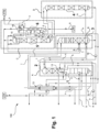
- FIG. 1 an air separation plant according to the invention for obtaining an argon product is shown schematically and designated overall by 100.
- the air separation plant has as separation units a high-pressure column 1, a two-part low-pressure column with a foot section 2 and a head section 3, a crude argon column also divided into two parts with a foot section 4 and a head section 5 and a pure argon column 6.
- the foot section 2 and the head section 3 of the low-pressure column are structurally separated from one another.
- the head section 3 of the low-pressure column is arranged next to the high-pressure column 1 in a vertical plan view, the foot section 2 of the low-pressure column above it.
- the foot section 2 and the head section 3 of the low-pressure column together correspond functionally to a conventional low-pressure column of a Linde double column.
- the high-pressure column 1 and the two column sections 2 and 3 of the low-pressure column thus form a distillation column system for nitrogen-oxygen separation.
- cooled and compressed feed air is fed into the high-pressure column 1 in the form of two streams a and b.
- the streams a and b can be a so-called turbine stream (stream a) on the one hand and a so-called throttle stream (stream b) on the other.
- the air separation plant 100 according to the invention can thus be designed for internal compression.
- the provision of the streams a and b is, for example, in the EP 2 026 024 A1
- atmospheric air can be sucked in by an air compressor via a filter and compressed there to an absolute pressure of 5.0 to 7.0 bar, preferably about 5.5 bar.
- the air can also be compressed to a higher pressure in the air compressor itself or in a further compressor (post-compressor) arranged downstream of it and later expanded via an expansion machine, whereby, for example, part of the cooling requirement of the air separation plant 100 can be covered.
- the air can be cooled, for example in a direct contact cooler in direct heat exchange with cooling water.
- the cooling water can be supplied, for example, from an evaporative cooler and/or from an external source.
- the compressed and cooled air can then be cleaned in a cleaning device. This can, for example, have a pair of containers filled with a suitable adsorption material, preferably molecular sieve.
- the cleaned air is then cooled to approximately the dew point, usually in a main heat exchanger.
- the operating pressures - respectively at the head or the upper part of the head section - are 4.5 to 6.5 bar, preferably about 5.0 bar in the high-pressure column 1 and 1.2 to 1.7 bar, preferably about 1.3 bar in the low-pressure column 2, 3.
- the foot section 2 and the head section 3 of the low-pressure column are preferably operated at essentially the same pressure, although this does not exclude certain pressure differences, for example due to line resistances.
- the high-pressure column 1 and the base section 2 of the low-pressure column are connected in a heat-exchanging manner via a main condenser 12 and are designed as a structural unit.
- the invention can also be used in principle in systems in which the high-pressure column 1 and the low-pressure column (or its base section 2) are arranged separately from one another and have a separate main condenser, i.e. one that is not integrated into the columns.
- Air which is liquefied when the feed air stream b is fed into the high-pressure column 1 can be partly discharged as a corresponding stream c, heated in a subcooling countercurrent device 13, and then used elsewhere or recompressed and provided as feed air stream a, b.
- An oxygen-enriched fraction d is withdrawn from the bottom of the high-pressure column 1, subcooled in the subcooling countercurrent device 13 and, as stream e, partly cooled further in a bottom evaporator 14 of the pure argon column 6. Another part can be passed past the bottom evaporator 14. Part of the stream e flows into the evaporation space of a top condenser 15 of the top section 5 of the two-part crude argon column, another part into the evaporation space of a top condenser 16 of the pure argon column 6. The portion of the oxygen-enriched fraction evaporated in the top condensers 15 and 16 is fed as stream f to the top section 3 of the low-pressure column at a first intermediate point. The remaining liquid portions are fed as stream g to a second intermediate point of the top section 3 of the low-pressure column, which is above the first intermediate point.
- Gaseous nitrogen from the top of the high-pressure column 1 can be partly heated as stream h, for example in the main heat exchanger (not shown), to cool the feed air to approximately ambient temperature and then, for example as in the EP 2 026 024 A1 presented, will be discussed further.
- the remaining gaseous nitrogen from the top of the high-pressure column 1 is at least partially condensed in the main condenser 12.
- the liquid nitrogen produced in this way is partially fed to the high-pressure column 1 as reflux.
- Another part is passed as stream i to the upper part of the top section 3 of the low-pressure column after subcooling in the subcooling countercurrent 13.
- a gaseous nitrogen stream j from the top of the top section 3 of the low-pressure column can be used in different ways or reused in the air separation plant after passing through the subcooling countercurrent 13.
- a liquid oxygen stream k from the sump of the foot section 2 of the low-pressure column can be pressurized by means of a pump 17 and then fed to a liquid oxygen tank (LOX), for example. Part of this oxygen can also be evaporated to provide gaseous compressed oxygen (so-called internal compression).
- LOX liquid oxygen tank
- a stream I flows from the upper part of the foot section 2 of the low-pressure column into the head section 3 of the low-pressure column in its lower region, whereby the foot section 2 and the head section 3 of the low-pressure column are partially functionally coupled.
- an argon-rich stream m is withdrawn from the head section 3 of the low-pressure column and fed into the foot section 4 of the crude argon column.
- the feed takes place directly above the bottom of the foot section 4 of the crude argon column.
- Bottom liquid from the bottom of the head section 3 of the low-pressure column and from the bottom of the foot section 4 of the crude argon column is fed back into the foot section 2 of the low-pressure column via a pump 18 as stream n.
- the top condenser 15 of the top section 5 of the crude argon column can be designed as a reflux condenser. Gas from the upper end of the top section 5 of the crude argon column flows into the reflux passages at the bottom and is partially condensed there. The condensate produced thereby flows downwards in countercurrent to the rising gas in the reflux passages and is used as liquid reflux in the top section 5 of the crude argon column.
- the top condenser 15 On the evaporation side, the top condenser 15 is designed as a bath condenser.
- the cooling fluid which is formed here by the liquid oxygen-enriched fraction from the high-pressure column 1, flows into the evaporation passages at the bottom via one or more side openings and is partially evaporated there.
- the top condenser 15 is therefore designed as a bath evaporator on the evaporation side.
- a crude argon stream n is taken in gaseous form from the upper end of the return passages via a side header and fed to the pure argon column 6 at an intermediate point.
- the top condenser 16 of the pure argon column 6 is designed conventionally on the liquefaction side in the example, i.e. a top gas stream o of the pure argon column 6 flows from top to bottom through the liquefaction passages.
- the top condenser 16 of the pure argon column 6 and/or the main condenser 12 could also be designed as return condensers.
- a residual gas stream p is taken from the top condenser 16 of the pure argon column 6 and, in the example, blown off into the atmosphere (ATM). Alternatively, it can be fed back into the high-pressure column 1 or the low-pressure column 2, 3 and/or in front of the air compressor via a separate blower.
- the bottom liquid of the pure argon column 6 is partially evaporated as stream p in the bottom evaporator 14 and the vapor generated is used as rising gas in the pure argon column 6. The remainder is removed as liquid pure argon product stream q (LAR).
- A designates a first coldbox, which is designed to accommodate the high-pressure column 1 and the foot section 2 of the low-pressure column.
- a second coldbox B can be designed to accommodate the head section 3 of the low-pressure column.
- a third coldbox C is designed to accommodate the head section 5 of the crude argon column.
- the head section 3 of the low-pressure column and the head section 5 of the high-pressure column can also be arranged in a common coldbox.
- Such a coldbox can, for example, have a height of 40 m.
- a fourth coldbox D is shown in a reduced size in the example shown and also has, for example, a height of 40 m.
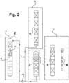
- FIG 2 an air separation plant for obtaining an argon product according to a further embodiment of the invention is shown in an even more schematic manner.
- this air separation plant only columns 2 to 6 are shown, and a representation of the corresponding connections, pumps and heat exchangers has been largely omitted.
- a foot section 4 of the crude argon column is arranged above the head section 3 of the low-pressure column.
- the crude argon column can be subdivided at a different location than that shown in the figure, provided this is expedient for the arrangement according to the invention.
- fluid from the foot section 4 of the crude argon column and from the head section 3 of the low-pressure column can be pumped by means of the pump 18 as stream n into the foot section 3 of the low-pressure column.
- This also applies to alternative arrangements in which the foot section 4 and/or the head section 5 of the crude argon column is arranged geodetically at least partially next to the head section 3 of the low-pressure column. All column sections 1 to 4 can also be arranged geodetically next to each other, at least partially.
- the diameter of the columns can be influenced accordingly by the choice of fittings in the respective columns (sieve trays, packings with different densities), thereby achieving further structural adaptation if necessary.
Landscapes
- Engineering & Computer Science (AREA)
- Physics & Mathematics (AREA)
- Mechanical Engineering (AREA)
- Thermal Sciences (AREA)
- General Engineering & Computer Science (AREA)
- Health & Medical Sciences (AREA)
- Emergency Medicine (AREA)
- Separation By Low-Temperature Treatments (AREA)
Description
- Die vorliegende Erfindung betrifft eine Luftzerlegungsanlage, ein Verfahren zur Gewinnung eines Argonprodukts durch Tieftemperaturzerlegung von Luft und ein Verfahren zur Erstellung einer entsprechenden Luftzerlegungsanlage.
- Die Gewinnung von Argon durch Tieftemperaturzerlegung von Luft ist beispielsweise im Artikel "Noble Gases" in Ullmann's Encyclopedia of Industrial Chemistry (doi: 10.1002/14356007.a17_485) beschrieben. Wie dort beispielsweise in Figur 18 dargestellt, kann Argon in herkömmlichen Luftzerlegungsanlagen mit bekannten Doppelsäulensystemen zur Stickstoff-Sauerstoff-Trennung und einer zusätzlichen Argongewinnungseinheit gewonnen werden.
- In solchen Doppelsäulensystemen reichert sich Argon im Bereich des sogenannten Argonübergangs in der Niederdrucksäule (auch als Argonbauch bzw. Argonbubble bezeichnet) an und erreicht dort Konzentrationen in der Gasphase von bis zu 15%. In der praktischen Anwendung wird ein argonangereicherter Strom etwas unterhalb dieses Argonmaximums aus der Niederdrucksäule abgezogen, damit dieser einen geringeren Stickstoffgehalt aufweist.
- Der argonangereicherte Strom wird in eine sogenannte Rohargonsäule überführt. Bei der Rohargonsäule handelt es sich um eine Trennsäule zur Argon-Sauerstoff-Trennung. In herkömmlichen Luftzerlegungsanlagen kann die Rohargonsäule durch eine einteilige Säule gebildet sein, es sind jedoch auch zwei- oder mehrteilige Säulen, beispielsweise in der
EP 0 628 777 B1 , beschrieben. - In bekannte Rohargonsäulen wird ein argonangereicherter Strom mit einem Argongehalt von beispielsweise 10% eingespeist. In der Rohargonsäule wird hieraus ein argonreicher Strom gewonnen, der in einer nachgeschalteten Reinargonsäule nochmals aufgereinigt werden kann. In der Reinargonsäule kann ein Argonprodukt mit einem Gehalt von bis zu 99,9999% Argon oder mehr gewonnen werden. Dieses Argonprodukt wird üblicherweise in flüssiger Form gewonnen, um Lagerung und Transport zu erleichtern.
- Prozesse zur Argongewinnung der erläuterten Art sind beispielsweise aus den folgenden Druckschriften bekannt:
DE 2 325 422 A ,EP 0 171 711 A2 ,EP 0 377 117 B2 (entsprichtUS 5 019 145 A ),DE 403 07 49 A1 ,EP 0 628 777 B1 (US 5 426 946 A ),EP 0 669 508 A1 (US 5 592 833 A ),EP 0 669 509 B1 (US 5 590 544 A ),EP 0 942 246 A2 ,EP 1 103 772 A1 ,DE 196 09 490 A1 (US 5 669 237 A ),EP 1 243 882 A1 (US 2002/178747 A1 ),EP 1 243 881 A1 (US 2002/189281 A1 ) undFR 2 964 451 A3 - Bei der Erstellung von Luftzerlegungsanlagen zur Argongewinnung ergeben sich Probleme aufgrund der Dimensionen der verwendeten Säulen, insbesondere der Rohargonsäule. Ein Doppelsäulensystem zur Stickstoff-Sauerstoff-Trennung kann insgesamt eine Höhe von beinahe 60 m erreichen, eine Rohargonsäule in einteiliger Form liegt ebenfalls in diesem Bereich.
- Entsprechende Luftzerlegungsanlagen sind kaum mehr vorfertigbar, weil die jeweiligen Komponentengruppen in der Regel nicht mehr über längere Strecken transportiert werden können. Dies bedeutet, dass sie am jeweiligen Zielort erstellt werden müssen. Dies ist aus unterschiedlichen Gründen nachteilig, unter anderem deshalb, weil entsprechendes Personal am Zielort entweder nicht verfügbar oder teuer ist. Der Aufwand zur Erstellung entsprechender Luftzerlegungsanlagen erhöht sich damit signifikant.
- Wünschenswert ist hingegen die weitgehend modularisierte Erstellung einer entsprechenden Luftzerlegungsanlage am Fertigungsort. Die einzelnen Komponenten werden dort vorzugsweise bereits in den entsprechenden Coldboxen untergebracht und müssen am Zielort nur noch miteinander verbunden werden. Hierfür können vorteilhafterweise ebenfalls Module, sogenannte Piping Skids, eingesetzt werden.
- In der
US 2001/0001364 A1 , welche eine Luftzerlegungsanlage entsprechend des Oberbegriffs von Anspruch 1 offenbart, wird vorgeschlagen, einen Teil der Säulen einer Luftzerlegungsanlage zur Argongewinnung zweiteilig auszubilden und eine Anordnung vorzunehmen, die es erlaubt, eine Coldbox für diese Säulen zu verkleinern. - Wenngleich diese Aufteilung die Erstellung von Luftzerlegungsanlagen erleichtert, besteht weiter der Bedarf nach Verbesserungen. Der Erfindung liegt daher die Aufgabe zugrunde, eine Luftzerlegungsanlage der eingangs genannten Art wirtschaftlich besonders günstig zu erstellen und zu betreiben.
- Vor diesem Hintergrund schlägt die vorliegende Erfindung eine Luftzerlegungsanlage, ein Verfahren zur Gewinnung eines Argonprodukts durch Tieftemperaturzerlegung von Luft und ein Verfahren zur Erstellung einer entsprechenden Luftzerlegungsanlage mit den Merkmalen der unabhängigen Patentansprüche vor. Bevorzugte Ausgestaltungen sind jeweils Gegenstand der Unteransprüche sowie der nachfolgenden Beschreibung.
- Erfindungsgemäß wird eine Luftzerlegungsanlage vorgeschlagen, die zur Gewinnung eines Argon enthaltenden Produkts durch Tieftemperaturzerlegung von verdichteter und abgekühlter Einsatzluft eingerichtet ist. Die Luftzerlegungsanlage weist eine Hochdrucksäule, eine mehrteilig ausgebildete Niederdrucksäule und eine mehrteilig ausgebildete Rohargonsäule auf. Die mehrteilig ausgebildete Niederdrucksäule und die mehrteilig ausgebildete Rohargonsäule weisen jeweils zumindest einen Fußabschnitt und einen räumlich getrennt hiervon angeordneten Kopfabschnitt auf. Insbesondere sind die mehrteilig ausgebildete Niederdrucksäule und die mehrteilig ausgebildete Rohargonsäule jeweils zweiteilig ausgebildet.
- Die Luftzerlegungsanlage arbeitet auf Grundlage der eingangs erläuterten Prinzipien, wobei ein argonangereicherter Strom der Niederdrucksäule der Luftzerlegungsanlage entnehmbar ist.
- Bei dem "Argon enthaltenden Produkt" kann es sich beispielsweise um flüssiges Argon (LAR), gasförmiges Argon (GAR, ggf. durch sogenannte Innenverdichtung erhalten) oder sogenanntes Fake Argon (unreines Argon, das gasförmig im kalten Zustand zu einem Restgas zugegeben wird) handeln. Die Erfindung wird nachfolgend vorwiegend am Beispiel von flüssigem Reinargon (LAR) dargestellt, das kurz als "Argonprodukt" bezeichnet wird.
- Eine "zweiteilig ausgebildete" Säule ist, wie erwähnt derart ausgebildet, dass die zwei Abschnitte (Kopfabschnitt und Fußabschnitt) räumlich voneinander getrennt anordenbar sind. Bekannte Luftzerlegungsanlagen können beispielsweise Säulensysteme zur Stickstoff-Sauerstoff-Trennung aufweisen, bei denen die Hochdrucksäule und die Niederdrucksäule getrennt voneinander angeordnet und über einen Kopfkondensator wärmetauschend verbunden sind. Derartige Säulensysteme sind "zweiteilig ausgebildet". Der Begriff "zweiteilig ausgebildet" grenzt entsprechende Konfigurationen damit von baulichen Einheiten ab, in denen Komponenten dauerhaft miteinander verbunden und nicht getrennt voneinander anordenbar sind.
- Mit "Fußabschnitt" und "Kopfabschnitt" werden jeweils die Abschnitte der zweiteilig ausgebildeten Säulen bezeichnet, die in ihrer Funktion, insbesondere hinsichtlich der dort anfallenden Fraktionen bzw. Ströme, den untersten bzw. obersten Abschnitten herkömmlicher, einteilig ausgebildeter Säulen entsprechen. Ein Fußabschnitt weist beispielsweise einen Sumpfbehälter auf, ein Kopfabschnitt weist beispielsweise einen Kopfkondensator auf. Der Kopfabschnitt ist damit der Teil der Säulen, der mit einem entsprechenden Kondensator verbunden ist, und in dem ein Rücklauf auf die entsprechenden Säulen aufgegeben wird. In einer einteilig ausgebildeten Niederdrucksäule bekannter Luftzerlegungsanlagen wird im Sumpf eine sauerstoffreiche Flüssigfraktion gewonnen, die als Sauerstoffprodukt abgezogen werden kann. Dies erfolgt damit auch in einem Sumpf eines Fußabschnitts einer zweiteilig ausgebildeten Niederdrucksäule. Am Kopf einer einteilig ausgebildeten Niederdrucksäule bekannter Luftzerlegungsanlagen kann entsprechend ein gasförmiges Stickstoffprodukt abgezogen werden, gleiches gilt für den oberen Teil eines Kopfabschnitts einer zweiteilig ausgebildeten Niederdrucksäule. Am Kopf einer einteilig ausgebildeten Rohargonsäule - und entsprechend am oberen Teil eines Kopfabschnitts einer zweiteilig ausgebildeten Rohargonsäule - wird ein Rohargonstrom abgezogen und in eine Reinargonsäule überführt, vom Sumpf einer einteilig ausgebildeten Rohargonsäule - und entsprechend vom Sumpf eines Fußabschnitts einer zweiteilig ausgebildeten Rohargonsäule - wird das anfallende Sumpfprodukt in die Niederdrucksäule zurückgespeist.
- Weist eine "mehrteilig" ausgebildete Niederdruck- und/oder Rohargonsäule mehr als zwei Teile auf, sind zusätzlich Zwischenabschnitte zwischen Fuß- und Kopfabschnitt vorgesehen. Die einzelnen Abschnitte (Fuß-, Kopf- und gegebenenfalls Zwischenabschnitte) sind mittels Leitungen und gegebenenfalls Pumpen miteinander verbunden, um auf diese Weise einen Betrieb, wie er auch mit einer jeweils einteiligen Säule erfolgt, darzustellen.
- Die erfindungsgemäße Luftzerlegungsanlage ist in gängiger Weise konfiguriert, was bedeutet, dass in der Hochdrucksäule aus zumindest einem Teil von Einsatzluft, die beispielsweise in Form mehrerer Einsatzluftströme bereitgestellt werden kann, zumindest ein sauerstoffreicher Strom gewinnbar ist. Der sauerstoffreiche Strom kann zumindest zum Teil in die mehrteilige Niederdrucksäule überführt werden, und zwar zunächst in deren Fußabschnitt. In der mehrteiligen Niederdrucksäule kann, wie erläutert, am sogenannten Argonübergang aus zumindest einem Teil des sauerstoffangereicherten Stroms zumindest ein argonreicher Strom gewonnen werden. Dieser kann in die mehrteilige Rohargonsäule überführt werden, und zwar zunächst ebenfalls in deren Fußabschnitt. In der Rohargonsäule kann zumindest aus einem Teil des argonangereicherten Stroms zumindest ein argonreicher Strom gewonnen werden.
- Für entsprechende Fluide werden hier die Begriffe "Ströme" und "Fraktionen" verwendet. Bei einem "Strom" handelt es sich beispielsweise um ein Fluid, das kontinuierlich in einer entsprechenden Leitung geführt wird. Eine "Fraktion" stellt einen Anteil eines Ausgangsgemischs dar, beispielsweise von Luft, der aus dem Ausgangsgemisch abgetrennt werden kann. Eine derartige Fraktion kann jederzeit als Strom in einem entsprechenden Leitungssystem oder in einer Säule geführt werden.
- Ein Strom oder eine Fraktion kann bezüglich einer oder mehrerer enthaltener Komponenten "angereichert" sein, wobei eine angereicherte Fraktion bzw. ein angereicherter Strom einen höheren Gehalt einer oder mehrerer entsprechend bezeichneter Komponenten als das Ausgangsgemisch aufweist. Insbesondere liegt eine Anreicherung dann vor, wenn der Gehalt mindestens dem zwei-, fünf-, zehn- oder einhundertfachen des entsprechenden Gehalts im Ausgangsgemisch entspricht. Ein bezüglich einer oder mehrerer Komponenten "reicher" Strom weist überwiegend die entsprechende(n) Komponente(n) auf. Beispielsweise kann ein argonreicher Strom wenigstens 80%, 90%, 95% oder 99% Argon auf molarer, Gewichts- oder Volumenbasis aufweisen.
- Die erfindungsgemäße Luftzerlegungsanlage zeichnet sich dadurch aus, dass zumindest ein flüssiger Strom aus einem unteren Bereich des Kopfabschnitts der Niederdrucksäule und aus einem unteren Bereich des Fußabschnitts der Rohargonsäule mittels einer gemeinsamen Pumpe in einen oberen Bereich des Fußabschnitts der Niederdrucksäule überführbar sind.
- Die Erfindung kann unterschiedliche Anordnungen der Säulen bzw. ihrer Abschnitte umfassen. So kann der Fußabschnitt und/oder der Kopfabschnitt der Rohargonsäule geodätisch zumindest teilweise neben dem Kopfabschnitt der Niederdrucksäule angeordnet sein. In diesem Fall können auch die Hochdrucksäule, der Kopfabschnitt der Niederdrucksäule, der Fußabschnitt und der Kopfabschnitt der Rohargonsäule geodätisch zumindest teilweise nebeneinander angeordnet sein. Gemäß einer weiteren Ausführungsform ist vorgesehen, dass der Fußabschnitt oder der Kopfabschnitt der Rohargonsäule geodätisch vollständig oberhalb des Kopfabschnitts der Niederdrucksäule angeordnet ist. Vorzugsweise sind auch der Fußabschnitt der Niederdrucksäule in vertikaler Draufsicht neben ihrem Kopfabschnitt und der Fußabschnitt der Rohargonsäule in vertikaler Draufsicht neben ihrem Kopfabschnitt angeordnet. Gleichzeitig sind, wenn der Fußabschnitt oder der Kopfabschnitt der Rohargonsäule geodätisch vollständig oberhalb des Kopfabschnitts der Niederdrucksäule angeordnet ist, die Hochdrucksäule und der Fußabschnitt der Niederdrucksäule einerseits und der Kopfabschnitt oder der Fußabschnitt der Rohargonsäule und der Kopfabschnitt der Niederdrucksäule in vertikaler Draufsicht zumindest teilweise übereinander angeordnet.
- Im Rahmen der vorliegenden Anmeldung ist mit "geodätisch zumindest teilweise neben" gemeint, dass der tiefste Punkt der jeweils näher bezeichneten Säule oder des Säulenabschnitts (hier beispielsweise des Fußabschnitts und/oder des Kopfabschnitts der Rohargonsäule) unterhalb des höchsten Punkts der entsprechenden anderen Säule oder des Säulenabschnitts (hier beispielsweise des Kopfabschnitts der Niederdrucksäule) liegt. Die tiefsten Punkte der jeweils näher bezeichneten Säulen oder Säulenabschnitte können auch auf einer Ebene liegen. In der erwähnten Ausführungsform, in der der Fußabschnitt und/oder der Kopfabschnitt der Rohargonsäule geodätisch zumindest teilweise neben dem Kopfabschnitt der Niederdrucksäule angeordnet ist, existiert also eine horizontale Schnittebene, die sowohl den Fußabschnitt und/oder den Kopfabschnitt der Rohargonsäule als auch den Kopfabschnitt der Niederdrucksäule schneidet.
- Entsprechend ist mit "geodätisch vollständig oberhalb" gemeint, dass der tiefste Punkt der jeweils näher bezeichneten Säule oder des Säulenabschnitts (hier beispielsweise des Fußabschnitts oder des Kopfabschnitts der Rohargonsäule) oberhalb des höchsten Punkts der entsprechenden anderen Säule oder des Säulenabschnitts (hier beispielsweise des Kopfabschnitts der Niederdrucksäule) liegt. Würde in dem erläuterten Fall der Fußabschnitt bzw. der Kopfabschnitt der Rohargonsäule, der geodätisch vollständig oberhalb des Kopfabschnitts der Niederdrucksäule angeordnet ist, an seinem tiefsten Punkt fluidisch mit dem Kopfabschnitt der Niederdrucksäule verbunden, würde eine Flüssigkeit, Druckunterschiede vernachlässigt, vollständig in den Kopfabschnitt der Niederdrucksäule abfließen.
- Hierbei ist der "tiefste Punkt" einer Säule oder eines Säulenabschnitts jeweils die tiefste Stelle am Boden eines bodenseitig angeordneten Behälters, beispielsweise eines Sumpfbehälters, oder des gesamten Innenraums der Säule oder des Säulenabschnitts. Die eventuell hiermit verbundenen Leitungen zählen nicht zur Säule. Der "höchste Punkt" einer Säule oder eines Säulenabschnitts ist das Dach der Säule oder eines Säulenabschnitts. Weist eine Säule oder ein Säulenabschnitt einen Kopfkondensator auf, ist dessen höchster Punkt der höchste Punkt der Säule oder des Säulenabschnitts.
- Eine Anordnung einer Komponente "in vertikaler Draufsicht neben" meint hier eine Anordnung, in der die entsprechenden Komponenten in vertikaler Projektion nebeneinander angeordnet sind. Dies schließt nicht aus, dass die entsprechenden Elemente in unterschiedlichen (geodätischen) Höhen zueinander angeordnet sind. Beispielsweise kann der Fußabschnitt der Niederdrucksäule in vertikaler Draufsicht neben dem Kopfabschnitt der Niederdrucksäule angeordnet sein, die höhenmäßige Anordnung kann jedoch derart unterschiedlich sein, dass der geodätisch höchste Punkt des Kopfabschnitts der Niederdrucksäule noch unterhalb des geodätisch tiefsten Punkts des Fußabschnitts der Niederdrucksäule liegt. Wenn die Komponenten hingegen "in vertikaler Draufsicht zumindest teilweise übereinander" angeordnet sind, überschneiden sich ihre Umfangslinien zumindest zum Teil. Beispielsweise kann ein Rohargonbehälter seitlich verschoben werden, um platzsparender bauen zu können.
- Die erfindungsgemäße Anordnung in den erwähnten Ausführungsformen erweist sich als besonders vorteilhaft, weil hierdurch entsprechende Luftzerlegungsanlagen mit deutlich geringerer Höhe erstellt werden können. Beispielsweise kann mittels der erfindungsgemäßen Maßnahmen eine Luftzerlegungsanlage mit einer Rohargonsäule mit einer wirksamen Höhe von ca. 60 m durch eine entsprechende Aufteilung und Anordnung in einer Gesamtbauhöhe von ca. 40 m erstellt werden.
- Die Rohargonsäule mit der genannten Höhe wird hierzu in beispielsweise zwei Teile unterteilt. Der Kopfabschnitt der ebenfalls zweigeteilten Niederdrucksäule kann geodätisch unterhalb des Kopf- oder Fußabschnitts der Rohargonsäule in einer gemeinsamen Coldbox plaziert werden. Diese Anordnung weist eine Reihe zusätzlicher Vorteile auf, die nachfolgend erläutert werden. Der Fußabschnitt der Niederdrucksäule kann mit der Hochdrucksäule eine bauliche Einheit bilden und als solche ebenfalls in einer entsprechenden Coldbox plaziert werden. Die Hochdrucksäule und der Fußabschnitt der Niederdrucksäule können über einen Hauptkondensator wärmetauschend miteinander verbunden sein. Diese Konfiguration entspricht einer herkömmlichen Luftzerlegungsanlage mit einer Linde-Doppelsäule.
- Die entsprechende Coldbox für den Kopf- oder Fußabschnitt der Rohargonsäule und den Kopfabschnitt der Niederdrucksäule misst nur ca. 40 m. Der Transport ist damit erleichtert. Ähnliches gilt für die Coldbox, die die Hochdrucksäule und den Fußabschnitt der Niederdrucksäule enthält. Der verbleibende Abschnitt der Rohargonsäule benötigt ebenfalls eine Bauhöhe von ca. 40 m.
- Die Luftzerlegungsanlage kann daher besonders kostengünstig erstellt und, insbesondere aufgrund der erwähnten erfindungsgemäßen Pumpenanordnung, betrieben werden. Insbesondere kann eine derartige Luftzerlegungsanlage vollständig am Fertigungsort vorgefertigt und in den entsprechenden Coldboxen in Form modularer Einheiten an den Zielort transportiert werden. Eine aufwendige Verbindung einer Vielzahl von Komponenten am Zielort ist damit nicht erforderlich. Die Anlagenkomponenten können im Werk besonders einfach in ihrer Gesamtheit auf ihre Funktionsfähigkeit überprüft werden, was gegebenenfalls eine aufwendige Fehlerdiagnose an Einzelkomponenten am Zielort erübrigt.
- Besondere Vorteile ergeben sich beim Betrieb der erfindungsgemäßen Luftzerlegungsanlage dadurch, dass, wie erwähnt, ein flüssiger Strom aus einem unteren Bereich des Kopfabschnitts der Niederdrucksäule und ein flüssiger Strom aus einem unteren Bereich des Fußabschnitts der Rohargonsäule mittels einer gemeinsamen Pumpe in einen oberen Bereich des Fußabschnitts der Niederdrucksäule überführt werden. Die Bereitstellung mehrerer unterschiedlicher Pumpen und damit ein entsprechender Energieverbrauch sowie der damit verbundene Wärmeeintrag und eine entsprechende Wartungsanfälligkeit entfallen hierdurch vollständig.
- Die Niederdrucksäule wird hierbei vorzugsweise derart ausgebildet und betrieben, dass sich der erwähnte Argonübergang an der Trennstelle zwischen dem Kopf- und dem Fußabschnitt der Niederdrucksäule befindet. Wie erwähnt, wird in der praktischen Anwendung ein argonangereicherter Strom etwas unterhalb des eigentlichen Argonmaximums aus der Niederdrucksäule abgezogen, damit dieser einen geringeren Stickstoffgehalt aufweist. Dies kann bei der Wahl der Trennstelle und beim Betrieb der Niederdrucksäule berücksichtigt werden. Im Ergebnis weisen die Ströme aus dem unteren Bereich des Fußabschnitts der Rohargonsäule und aus dem unteren Bereich des Kopfabschnitts der Niederdrucksäule gleiche oder ähnliche Argonkonzentrationen auf, so dass diese mittels der gemeinsamen Pumpe in den oberen Bereich des Fußabschnitts der Niederdrucksäule eingespeist werden können.
- Eine erfindungsgemäße Luftzerlegungsanlage kann in unterschiedlicher Konfiguration erstellt werden, insbesondere unter Verwendung von sogenannten Piping Skids, also von Verrohrungsmodulen, die auch eine vorgefertigte Verrohrung ermöglichen.
- Ferner umfasst die erfindungsgemäße Luftzerlegungsanlage vorteilhafterweise eine Reinargonsäule, in der sich Argon mit einer Reinheit im eingangs erwähnten Bereich gewinnen lässt. Die Reinargonsäule kann in einer der erwähnten Coldboxen oder separat dazu, insbesondere in einer eigenen Coldbox, angeordnet sein.
- Ein erfindungsgemäßes Verfahren umfasst die Gewinnung eines Argonprodukts durch Tieftemperaturzerlegung von verdichteter und abgekühlter Einsatzluft. Das erfindungsgemäße Verfahren profitiert von den zuvor erwähnten Vorteilen, so dass hierauf ausdrücklich verwiesen werden kann.
- Die Erfindung wird nachfolgend unter Bezugnahme auf die beigefügten Zeichnungen beschrieben, die bevorzugte Ausführungsformen der Erfindung zeigen.
-
-
Figur 1 zeigt schematisch eine Luftzerlegungsanlage zur Gewinnung eines Argonprodukts gemäß einer besonders bevorzugten Ausführungsform der Erfindung. -
Figur 2 zeigt schematisch eine Luftzerlegungsanlage zur Gewinnung eines Argonpodukts gemäß einer besonders bevorzugten Ausführungsform der Erfindung. - In den Figuren sind einander entsprechende Elemente mit identischen Bezugszeichen angegeben. Auf eine wiederholte Erläuterung derselben wird verzichtet.
- Es sei ausdrücklich betont, dass die Anordnung der Komponenten der in den
Figuren 1 und2 dargestellten Luftzerlegungsanlagen lediglich beispielhaft ist und dass insbesondere die Dimensionen der dort dargestellten Komponenten, insbesondere der Säulen, nicht maßstabsgerecht sind. Wie erwähnt weist die Rohargonsäule einer entsprechenden Luftzerlegungsanlage in der Regel die größte Höhe auf, was in der Zeichnung nicht maßstabsgerecht wiedergegeben ist. Auch Anlagen mit sogenannten Dummysäulen sind bekannt, aus denen nur Argon abgezogen wird, um einen Energievorteil zu erreichen. Derartige Säulen sind deutlich niedriger, also auch niedriger als die anderen Säulen. - In
Figur 1 ist eine erfindungsgemäße Luftzerlegungsanlage zur Gewinnung eines Argonprodukts schematisch dargestellt und insgesamt mit 100 bezeichnet. Die Luftzerlegungsanlage weist als Trenneinheiten eine Hochdrucksäule 1, eine zweigeteilte Niederdrucksäule mit einem Fußabschnitt 2 und einem Kopfabschnitt 3, eine ebenfalls zweigeteilte Rohargonsäule mit einem Fußabschnitt 4 und einem Kopfabschnitt 5 sowie eine Reinargonsäule 6 auf. Der Fußabschnitt 2 und der Kopfabschnitt 3 der Niederdrucksäule sind baulich voneinander getrennt. Der Kopfabschnitt 3 der Niederdrucksäule ist in vertikaler Draufsicht neben der Hochdrucksäule 1 angeordnet, der Fußabschnitt 2 der Niederdrucksäule darüber. Der Fußabschnitt 2 und der Kopfabschnitt 3 der Niederdrucksäule entsprechen zusammen funktional einer herkömmlichen Niederdrucksäule einer Linde-Doppelsäule. Die Hochdrucksäule 1 und die beiden Säulenabschnitte 2 und 3 der Niederdrucksäule bilden damit ein Destilliersäulensystem zur Stickstoff-Sauerstoff-Trennung. - Im dargestellten Ausführungsbeispiel wird abgekühlte und verdichtete Einsatzluft in Form zweier Ströme a und b in die Hochdrucksäule 1 eingespeist. Bei den Strömen a und b kann es sich um einen sogenannten Turbinenstrom (Strom a) einerseits und einen sogenannten Drosselstrom (Strom b) andererseits handeln. Die erfindungsgemäße Luftzerlegungsanlage 100 kann damit zur Innenverdichtung ausgebildet sein. Die Bereitstellung der Ströme a und b ist beispielsweise in der der
EP 2 026 024 A1 dargestellt. Beispielsweise kann atmosphärische Luft über ein Filter von einem Luftverdichter angesaugt und dort auf einen Absolutdruck von 5,0 bis 7,0 bar, vorzugsweise etwa 5,5 bar verdichtet werden. Die Luft kann in dem Luftverdichter selbst oder in einem stromab hiervon angeordneten weiteren Verdichter (Nachverdichter) auch auf einen höheren Druck verdichtet und später über eine Entspannungsmaschine entspannt werden, wodurch beispielsweise ein Teil des Kältebedarfs der Luftzerlegungsanlage 100 gedeckt werden kann. - Die Luft kann nach der Verdichtung beispielsweise in einem Direktkontaktkühler in direktem Wärmeaustausch mit Kühlwasser gekühlt werden. Das Kühlwasser kann beispielsweise aus einem Verdunstungskühler und/oder von einer äußeren Quelle zugeführt werden. Die verdichtete und gekühlte Luft kann dann in einer Reinigungsvorrichtung gereinigt werden. Diese kann beispielsweise ein Paar von Behältern aufweisen, die mit einem geeigneten Adsorptionsmaterial, vorzugsweise Molekularsieb, gefüllt sind. Die gereinigte Luft wird dann, i.d.R. in einem Hauptwärmetauscher, auf etwa Taupunkt abgekühlt.
- Die Betriebsdrücke - jeweils am Kopf bzw. dem oberen Teil des Kopfabschnitts - betragen 4,5 bis 6,5 bar, vorzugsweise etwa 5,0 bar in der Hochdrucksäule 1 und 1,2 bis 1,7 bar, vorzugsweise etwa 1,3 bar in der Niederdrucksäule 2, 3. Der Fußabschnitt 2 und der Kopfabschnitt 3 der Niederdrucksäule werden vorzugsweise bei im Wesentlichen gleichem Druck betrieben, was jedoch gewisse Druckunterschiede, beispielsweise aufgrund von Leitungswiderständen, nicht ausschließt.
- Die Hochdrucksäule 1 und der Fußabschnitt 2 der Niederdrucksäule stehen über einen Hauptkondensator 12 in wärmetauschender Verbindung und sind als bauliche Einheit ausgebildet. Die Erfindung ist jedoch grundsätzlich auch in Systemen einsetzbar, in denen die Hochdrucksäule 1 und die Niederdrucksäule (bzw. deren Fußabschnitt 2) getrennt voneinander angeordnet sind und einen separaten, d.h. nicht in die Säulen integrierten, Hauptkondensator aufweisen.
- Luft, die bei der Einspeisung des Einsatzluftstroms b in die Hochdrucksäule 1 verflüssigt wird, kann zum Teil als entsprechender Strom c abgeführt, in einem Unterkühlungs-Gegenströmer 13 erwärmt, und anschließend anderweitig verwendet oder erneut verdichtet und als Einsatzluftstrom a, b bereitgestellt werden.
- Eine sauerstoffangereicherte Fraktion d wird vom Sumpf der Hochdrucksäule 1 abgezogen, in dem Unterkühlungs-Gegenströmer 13 unterkühlt und als Strom e zu einem Teil in einem Sumpfverdampfer 14 der Reinargonsäule 6 weiter abgekühlt. Ein anderer Teil kann am Sumpfverdampfer 14 vorbeigeleitet werden. Ein Teil des Stroms e strömt in den Verdampfungsraum eines Kopfkondensators 15 des Kopfabschnitts 5 der zweigeteilten Rohargonsäule, ein anderer Teil in den Verdampfungsraum eines Kopfkondensators 16 der Reinargonsäule 6. Der in den Kopfkondensatoren 15 und 16 verdampfte Anteil der sauerstoffangereicherten Fraktion wird als Strom f dem Kopfabschnitt 3 der Niederdrucksäule an einer ersten Zwischenstelle zugeführt. Die flüssig verbliebenen Anteile werden als Strom g an einer zweiten Zwischenstelle des Kopfabschnitts 3 der Niederdrucksäule aufgegeben, die oberhalb der ersten Zwischenstelle liegt.
- Gasförmiger Stickstoff vom Kopf der Hochdrucksäule 1 kann zu einem Teil als Strom h, beispielsweise in dem nicht dargestellten Hauptwärmetauscher, zur Abkühlung der Einsatzluft auf etwa Umgebungstemperatur angewärmt und anschließend, beispielsweise wie in der
EP 2 026 024 A1 dargestellt, weiter behandelt werden. - Der restliche gasförmige Stickstoff vom Kopf der Hochdrucksäule 1 wird im Hauptkondensator 12 mindestens teilweise kondensiert. Der dabei erzeugte flüssige Stickstoff wird teilweise auf die Hochdrucksäule 1 als Rücklauf aufgegeben. Ein anderer Teil wird nach Unterkühlung in dem Unterkühlungs-Gegenströmer 13 als Strom i zum oberen Teil des Kopfabschnitts 3 der Niederdrucksäule geleitet. Ein gasförmiger Stickstoffstrom j vom Kopf des Kopfabschnitts 3 der Niederdrucksäule kann nach Durchlaufen des Unterkühlungs-Gegenströmers 13 auf unterschiedliche Weise genutzt bzw. in der Luftzerlegungsanlage weiterverwendet werden.
- Ein flüssiger Sauerstoffstrom k aus dem Sumpf des Fußabschnitts 2 der Niederdrucksäule kann mittels einer Pumpe 17 flüssig auf Druck gebracht und anschließend beispielsweise einem Flüssigsauerstofftank (LOX) zugeleitet werden. Ein Teil dieses Sauerstoffs kann auch zur Bereitstellung von gasförmigem Drucksauerstoff verdampft werden (sogenannte Innenverdichtung).
- Die Aufteilung der Niederdrucksäule in den Fußabschnitt 2 und den Kopfabschnitt 3 und deren Betrieb erfolgen derart, dass sich im unteren Teil des Kopfabschnitts 3 der Niederdrucksäule eine argonangereicherte Fraktion anreichert. Es handelt sich hierbei um den Bereich des sogenannten Argonübergangs (auch als Argonbauch oder Argonabschnitt bezeichnet). Diese Anreicherung ergibt sich, wie dem Fachmann bekannt, aus der Flüchtigkeit von Argon, die zwischen jener von Stickstoff und jener von Sauerstoff liegt. Werden in der Niederdrucksäule übliche Rücklaufverhältnisse verwendet, liegt der Argonübergang oberhalb und unterhalb der Zwischenstelle, an der eine sauerstoffangereicherte Fraktion eingespeist wird (Ströme f und g). Es können Argonkonzentrationen von bis zu 15% in der Dampfphase erreicht werden. Um die Stickstoffkonzentration zu reduzieren, wird der argonangereicherte Strom jedoch üblicherweise unterhalb dieser Zwischenstelle abgezogen, wie hier der Fall (Strom m).
- In der Luftzerlegungsanlage 100 strömt ein Strom I vom oberen Teil des Fußabschnitts 2 der Niederdrucksäule in den Kopfabschnitt 3 der Niederdrucksäule in dessen unterem Bereich, wodurch der Fußabschnitt 2 und der Kopfabschnitt 3 der Niederdrucksäule teilweise funktional gekoppelt werden. In gleicher Höhe wird aus dem Kopfabschnitt 3 der Niederdrucksäule ein argonreicher Strom m abgezogen und in den Fußabschnitt 4 der Rohargonsäule eingespeist. Die Einspeisung erfolgt unmittelbar über dem Sumpf des Fußabschnitts 4 der Rohargonsäule. Sumpfflüssigkeit vom Sumpf des Kopfabschnitts 3 der Niederdrucksäule und vom Sumpf des Fußabschnitts 4 der Rohargonsäule wird über eine Pumpe 18 als Strom n in den Fußabschnitt 2 der Niederdrucksäule zurückgeleitet. Hierdurch wird einerseits die funktionelle Kopplung des ersten Säulenabschnitts 2 und des zweiten Säulenabschnitts 3 der Niederdrucksäule vervollständigt und andererseits die Rohargonsäule über den Fußabschnitt 4 in das Trennsystem eingebunden.
- Der Kopfkondensator 15 des Kopfabschnitts 5 der Rohargonsäule kann als Rücklaufkondensator ausgebildet sein. Gas vom oberen Ende des Kopfabschnitts 5 der Rohargonsäule strömt unten in die Rücklaufpassagen ein und wird dort partiell kondensiert. Das dabei erzeugte Kondensat strömt im Gegenstrom zu dem aufsteigenden Gas in den Rücklaufpassagen nach unten und wird im Kopfabschnitt 5 der Rohargonsäule als flüssiger Rücklauf genutzt. Auf der Verdampfungsseite ist der Kopfkondensator 15 als Badkondensator ausgebildet. Das Kühlfluid, das hier durch die flüssige sauerstoffangereicherte Fraktion aus der Hochdrucksäule 1 gebildet wird, strömt unten über eine oder mehrere seitliche Öffnungen in die Verdampfungspassagen ein und wird dort teilweise verdampft. Durch den Thermosiphoneffekt wird Flüssigkeit mitgerissen, tritt zusammen mit dem verdampften Anteil am oberen Ende der Verdampfungspassagen aus und wird in das Flüssigkeitsbad zurückgeleitet. Der Kopfkondensator 15 ist also auf der Verdampfungsseite als Badverdampfer ausgebildet.
- Vom oberen Ende der Rücklaufpassagen wird über einen seitlichen Header ein Rohargonstrom n gasförmig entnommen und der Reinargonsäule 6 an einer Zwischenstelle zugeleitet. Der Kopfkondensator 16 der Reinargonsäule 6 ist in dem Beispiel auf der Verflüssigungsseite konventionell ausgeführt, d.h. ein Kopfgasstrom o der Reinargonsäule 6 strömt von oben nach unten durch die Verflüssigungspassagen. (Alternativ könnten auch der Kopfkondensator 16 der Reinargonsäule 6 und/oder der Hauptkondensator 12 als Rücklaufkondensatoren ausgebildet sein.) Vom Kopfkondensator 16 der Reinargonsäule 6 wird ein Restgasstrom p abgezogen und in dem Beispiel in die Atmosphäre (ATM) abgeblasen. Alternativ kann er über ein eigenes Gebläse in die Hochdrucksäule 1 oder die Niederdrucksäule 2, 3 und/oder vor den Luftverdichter zurückgeführt werden.
- Die Sumpfflüssigkeit der Reinargonsäule 6 wird zu einem Teil als Strom p in dem Sumpfverdampfer 14 verdampft und der dabei erzeugte Dampf wird als aufsteigendes Gas in der Reinargonsäule 6 genutzt. Der Rest wird als flüssiger Reinargonproduktstrom q (LAR) entnommen.
- Eine beispielhafte Integration der Komponenten der Luftzerlegungsanlage 100 in entsprechende Coldboxen ist in der
Figur 1 durch gestrichelte Linien veranschaulicht. Hierbei bezeichnet A eine erste Coldbox, die zur Aufnahme der Hochdrucksäule 1 und des Fußabschnitts 2 der Niederdrucksäule eingerichtet ist. Eine zweite Coldbox B kann zur Aufnahme des Kopfabschnitts 3 der Niederdrucksäule eingerichtet sein. Im dargestellten Beispiel ist eine dritte Coldbox C zur Aufnahme des Kopfabschnitts 5 der Rohargonsäule eingerichtet. Wie erläutert, können der Kopfabschnitt 3 der Niederdrucksäule und der Kopfabschnitt 5 der Hochdrucksäule (ggf. zusammen mit der Reinargonsäule 6) auch in einer gemeinsamen Coldbox angeordnet sein. Eine derartige Coldbox kann beispielsweise eine Höhe von 40 m aufweisen. Eine vierte Coldbox D ist im dargestellten Beispiel verkleinert gezeigt und weist beispielsweise ebenfalls eine Höhe von 40 m auf. - In
Figur 2 ist eine Luftzerlegungsanlage zur Gewinnung eines Argonprodukts gemäß einer weiteren Ausführungsform der Erfindung noch stärker schematisiert dargestellt. In dieser Luftzerlegungsanlage sind lediglich die Säulen 2 bis 6 dargestellt, auf eine Darstellung der entsprechenden Verbindungen, Pumpen und Wärmetauscher wurde weitgehend verzichtet. Wie ersichtlich, ist hier im Gegensatz zur Darstellung derFigur 1 ein Fußabschnitt 4 der Rohargonsäule oberhalb des Kopfabschnitts 3 der Niederdrucksäule angeordnet. In dieser alternativen Ausführungsform kann die Unterteilung der Rohargonsäule an einer anderen Stelle als in der Figur dargestellt erfolgen, sofern dies für die erfindungsgemäße Anordnung zweckmäßig ist. Auch hier ergibt sich der Vorteil, dass Fluid vom Fußabschnitt 4 der Rohargonsäule und vom Kopfabschnitt 3 der Niederdrucksäule mittels der Pumpe 18 als Strom n in den Fußabschnitt 3 der Niederdrucksäule gepumpt werden kann. Dies gilt auch für alternativ vorgesehene Anordnungen, in denen der Fußabschnitt 4 und/oder der Kopfabschnitt 5 der Rohargonsäule geodätisch zumindest teilweise neben dem Kopfabschnitt 3 der Niederdrucksäule angeordnet ist. Auch alle Säulenabschnitte 1 bis 4 können zumindest teilweise geodätisch nebeneinander angeordnet sein. - In allen dargestellten Fällen kann über die Wahl der Einbauten in die jeweiligen Säulen (Siebböden, Packungen mit unterschiedlicher Dichte) der Durchmesser der Säulen entsprechend beeinflusst und hierdurch ggf. eine weitere bauliche Anpassung erzielt werden.
Claims (15)
- Luftzerlegungsanlage (100), die zur Gewinnung eines Argon enthaltenden Produkts durch Tieftemperaturzerlegung von verdichteter, abgekühlter Einsatzluft eingerichtet ist, wobei die Luftzerlegungsanlage (100) eine Hochdrucksäule (1), eine mehrteilig ausgebildete Niederdrucksäule mit einem Fußabschnitt (2) und einem räumlich getrennt hiervon angeordneten Kopfabschnitt (3) sowie eine mehrteilig ausgebildete Rohargonsäule mit einem Fußabschnitt (4) und einem räumlich getrennt hiervon angeordneten Kopfabschnitt (5) aufweist, wobei in der Hochdrucksäule (1) aus zumindest einem Teil der Einsatzluft zumindest ein sauerstoffangereicherter Strom (d) gewinnbar ist, in der Niederdrucksäule aus zumindest einem Teil des sauerstoffangereicherten Stroms (d) zumindest ein argonangereicherter Strom (m) gewinnbar ist, und in der Rohargonsäule aus zumindest einem Teil des argonangereicherten Stroms (m) zumindest ein argonreicher Strom (n) gewinnbar ist, dadurch gekennzeichnet, dass die Luftzerlegungsanlage eine gemeinsamen Pumpe (18) aufweist, mittels derer zumindest ein flüssiger Strom (n) aus einem unteren Bereich des Kopfabschnitts (3) der Niederdrucksäule und aus einem unteren Bereich des Fußabschnitts (4) der Rohargonsäule in einen oberen Bereich des Fußabschnitts (2) der Niederdrucksäule überführbar sind, indem ein erster flüssiger Strom über eine erste Rohrleitung vom Sumpf des Kopfabschnitts (3) der Niederdrucksäule abziehbar ist und ein zweiter flüssiger Strom über eine zweite Rohrleitung vom Sumpf des Fußabschnitts (4) der Rohargonsäule abziehbar ist, wobei die erste und die zweite Rohrleitung in eine gemeinsame Rohrleitung eingeführt werden, die mit der gemeinsamen Pumpe (18) verbunden ist.
- Luftzerlegungsanlage (100) nach Anspruch 1, bei der der Fußabschnitt (4) und/oder der Kopfabschnitt (5) der Rohargonsäule geodätisch zumindest teilweise neben dem Kopfabschnitt (3) der Niederdrucksäule angeordnet ist.
- Luftzerlegungsanlage (100) nach Anspruch 1, bei der der Fußabschnitt (4) oder der Kopfabschnitt (5) der Rohargonsäule geodätisch vollständig oberhalb des Kopfabschnitts (3) der Niederdrucksäule angeordnet ist.
- Luftzerlegungsanlage (100) nach einem der vorstehenden Ansprüche, bei der der Fußabschnitt (2) der Niederdrucksäule in vertikaler Draufsicht neben deren Kopfabschnitt (3) und/oder der Fußabschnitt (4) der Rohargonsäule in vertikaler Draufsicht neben deren Kopfabschnitt (5) angeordnet ist.
- Luftzerlegungsanlage (100) nach einem der vorstehenden Ansprüche, bei der die Hochdrucksäule (1) mit dem Fußabschnitt (2) der Niederdrucksäule in einer Coldbox angeordnet ist.
- Luftzerlegungsanlage (100) nach einem der vorstehenden Ansprüche, bei der der Fußabschnitt (4) oder der Kopfabschnitt (5) der Rohargonsäule mit dem Kopfabschnitt (3) der Niederdrucksäule in einer Coldbox angeordnet ist.
- Luftzerlegungsanlage (100) nach Anspruch 6, bei der zumindest die Coldbox mit dem Fußabschnitt (2) oder dem Kopfabschnitt (3) der Niederdrucksäule und dem Kopfabschnitt (5) der Rohargonsäule mittels eines Verrohrungsmoduls an weitere Komponenten der Luftzerlegungsanlage (100) anbindbar ist.
- Luftzerlegungsanlage (100) nach einem der vorstehenden Ansprüche, bei der die Hochdrucksäule (1) und der Fußabschnitt (2) der Niederdrucksäule als bauliche Einheit ausgebildet und über einen Hauptkondensator (12) wärmetauschend miteinander verbunden sind.
- Luftzerlegungsanlage (100) nach einem der vorstehenden Ansprüche, die ferner eine Reinargonsäule (6) aufweist, wobei zumindest ein Fluid der Reinargonsäule mit dem sauerstoffangereicherten Strom (d) kühlbar ist.
- Verfahren zur Gewinnung eines Argon enthaltenden Produkts durch Tieftemperaturzerlegung von verdichteter, abgekühlte Einsatzluft in einer Luftzerlegungsanlage (100) nach einem der vorstehenden Ansprüche, wobei eine Hochdrucksäule (1), eine mehrteilig ausgebildete Niederdrucksäule mit einem Fußabschnitt (2) und einem räumlich getrennt hiervon angeordneten Kopfabschnitt (3) sowie eine mehrteilig ausgebildete Rohargonsäule mit einem Fußabschnitt (4) und einem räumlich getrennt hiervon angeordneten Kopfabschnitt (5) verwendet wird, wobei in der Hochdrucksäule (1) aus zumindest einem Teil der Einsatzluft zumindest ein sauerstoffangereicherter Strom (d) gewonnen wird, in der Niederdrucksäule aus zumindest einem Teil des sauerstoffangereicherten Stroms (d) zumindest ein argonangereicherter Strom (m) gewonnen wird und in der Rohargonsäule aus zumindest einem Teil des argonangereicherten Stroms (m) zumindest ein argonreicher Strom (n) gewonnen wird, und wobei zumindest ein flüssiger Strom (n) aus einem unteren Bereich des Kopfabschnitts (3) der Niederdrucksäule und aus einem unteren Bereich des Fußabschnitts (4) der Rohargonsäule mittels einer gemeinsamen Pumpe (18) in einen oberen Bereich des Fußabschnitts (2) der Niederdrucksäule überführt werden, indem ein erster flüssiger Strom über eine erste Rohrleitung vom Sumpf des Kopfabschnitts (3) der Niederdrucksäule abgezogen wird und ein zweiter flüssiger Strom über eine zweite Rohrleitung vom Sumpf des Fußabschnitts (4) der Rohargonsäule abgezogen wird, wobei die erste und die zweite Rohrleitung in eine gemeinsame Rohrleitung eingeführt werden, die mit der gemeinsamen Pumpe (18) verbunden ist.
- Verfahren nach Anspruch 10, bei der der Fußabschnitt (4) und/oder der Kopfabschnitt (5) der Rohargonsäule geodätisch zumindest teilweise neben dem Kopfabschnitt (3) der Niederdrucksäule angeordnet ist.
- Verfahren nach Anspruch 10, bei der der Fußabschnitt (4) oder der Kopfabschnitt (5) der Rohargonsäule geodätisch vollständig oberhalb des Kopfabschnitts (3) der Niederdrucksäule angeordnet ist.
- Verfahren zur Erstellung einer Luftzerlegungsanlage (100) nach einem der Ansprüche 1 bis 9, bei dem eine Hochdrucksäule (1), eine mehrteilig ausgebildete Niederdrucksäule mit einem Fußabschnitt (2) und einem Kopfabschnitt (3) sowie eine mehrteilig ausgebildete Rohargonsäule mit einem Fußabschnitt (4) und einem Kopfabschnitt (5) bereitgestellt wird, wobei ferner eine gemeinsame Pumpe (18) bereitgestellt wird, mittels derer zumindest ein flüssiger Strom (n) aus einem unteren Bereich des Kopfabschnitts (3) der Niederdrucksäule und aus einem unteren Bereich des Fußabschnitts (4) der Rohargonsäule in einen oberen Bereich des Fußabschnitts (2) der Niederdrucksäule überführbar sind, indem ein erster flüssiger Strom über eine erste Rohrleitung vom Sumpf des Kopfabschnitts (3) der Niederdrucksäule abziehbar ist und ein zweiter flüssiger Strom über eine zweite Rohrleitung vom Sumpf des Fußabschnitts (4) der Rohargonsäule abziehbar ist, wobei die erste und die zweite Rohrleitung in eine gemeinsame Rohrleitung eingeführt werden, die mit der gemeinsamen Pumpe (18) verbunden ist.
- Verfahren nach Anspruch 13, bei dem der Fußabschnitt (4) und/oder der Kopfabschnitt (5) der Rohargonsäule geodätisch zumindest teilweise neben dem Kopfabschnitt (3) der Niederdrucksäule angeordnet wird.
- Verfahren nach Anspruch 13, bei dem der Fußabschnitt (4) oder der Kopfabschnitt (5) der Rohargonsäule geodätisch vollständig oberhalb des Kopfabschnitts (3) der Niederdrucksäule angeordnet wird.
Priority Applications (1)
| Application Number | Priority Date | Filing Date | Title |
|---|---|---|---|
| EP14716232.5A EP2965029B2 (de) | 2013-03-06 | 2014-03-05 | Luftzerlegungsanlage, verfahren zur gewinnung eines argon enthaltenden produkts und verfahren zur erstellung einer luftzerlegungsanlage |
Applications Claiming Priority (3)
| Application Number | Priority Date | Filing Date | Title |
|---|---|---|---|
| EP13001127 | 2013-03-06 | ||
| PCT/EP2014/000553 WO2014135271A2 (de) | 2013-03-06 | 2014-03-05 | Luftzerlegungsanlage, verfahren zur gewinnung eines argon enthaltenden produkts und verfahren zur erstellung einer luftzerlegungsanlage |
| EP14716232.5A EP2965029B2 (de) | 2013-03-06 | 2014-03-05 | Luftzerlegungsanlage, verfahren zur gewinnung eines argon enthaltenden produkts und verfahren zur erstellung einer luftzerlegungsanlage |
Publications (3)
| Publication Number | Publication Date |
|---|---|
| EP2965029A2 EP2965029A2 (de) | 2016-01-13 |
| EP2965029B1 EP2965029B1 (de) | 2017-07-12 |
| EP2965029B2 true EP2965029B2 (de) | 2024-10-30 |
Family
ID=47900434
Family Applications (1)
| Application Number | Title | Priority Date | Filing Date |
|---|---|---|---|
| EP14716232.5A Active EP2965029B2 (de) | 2013-03-06 | 2014-03-05 | Luftzerlegungsanlage, verfahren zur gewinnung eines argon enthaltenden produkts und verfahren zur erstellung einer luftzerlegungsanlage |
Country Status (10)
| Country | Link |
|---|---|
| US (1) | US10591209B2 (de) |
| EP (1) | EP2965029B2 (de) |
| JP (1) | JP6257656B2 (de) |
| KR (1) | KR102178230B1 (de) |
| CN (1) | CN105026862B (de) |
| BR (1) | BR112015020093A2 (de) |
| CA (1) | CA2900122C (de) |
| CL (1) | CL2015002367A1 (de) |
| RU (1) | RU2659698C2 (de) |
| WO (1) | WO2014135271A2 (de) |
Families Citing this family (18)
| Publication number | Priority date | Publication date | Assignee | Title |
|---|---|---|---|---|
| EP3040665A1 (de) * | 2014-12-30 | 2016-07-06 | Linde Aktiengesellschaft | Destillationssäulen-system und anlage zur erzeugung von sauerstoff durch tieftemperaturzerlegung von luft |
| EP3067650B1 (de) | 2015-03-13 | 2018-04-25 | Linde Aktiengesellschaft | Anlage und verfahren zur erzeugung von sauerstoff durch tieftemperaturzerlegung von luft |
| DE102015009563A1 (de) | 2015-07-23 | 2017-01-26 | Linde Aktiengesellschaft | Luftzerlegungsanlage und Luftzerlegungsverfahren |
| EP3176526A1 (de) | 2015-12-03 | 2017-06-07 | Linde Aktiengesellschaft | Verfahren und anordnung zum überführen von fluid |
| US20170176098A1 (en) * | 2015-12-22 | 2017-06-22 | L'air Liquide, Societe Anonyme Pour L'etude Et L'exploitation Des Procedes Georges Claude | Systems and methods for automated startup of an air separation plant |
| US11740015B2 (en) * | 2018-01-26 | 2023-08-29 | L'air Liquide, Societe Anonyme Pour L'etude Et L'exploitation Des Procedes Georges Claude | Air separation unit by cryogenic distillation |
| CN108731376A (zh) * | 2018-04-18 | 2018-11-02 | 衢州杭氧气体有限公司 | 一种氩气生产工艺及其生产线 |
| JP6557763B1 (ja) * | 2018-08-09 | 2019-08-07 | レール・リキード−ソシエテ・アノニム・プール・レテュード・エ・レクスプロワタシオン・デ・プロセデ・ジョルジュ・クロード | 空気分離装置 |
| EP3614083A1 (de) * | 2018-08-22 | 2020-02-26 | Linde Aktiengesellschaft | Luftzerlegungsanlage, verfahren zur tieftemperaturzerlegung von luft mittels luftzerlegungsanlage und verfahren zur erstellung einer luftzerlegungsanlage |
| EP3614084A1 (de) * | 2018-08-22 | 2020-02-26 | Linde Aktiengesellschaft | Verfahren und anlage zur tieftemperaturzerlegung von luft |
| EP3614082A1 (de) | 2018-08-22 | 2020-02-26 | Linde Aktiengesellschaft | Luftzerlegungsanlage, verfahren zur tieftemperaturzerlegung von luft und verfahren zur erstellung einer luftzerlegungsanlage |
| JP7491716B2 (ja) * | 2020-03-31 | 2024-05-28 | 大陽日酸株式会社 | 空気液化分離装置 |
| US11828532B2 (en) | 2020-12-31 | 2023-11-28 | L'air Liquide Societe Anonyme Pour L'etude Et L'exploitation Des Procedes Georges Claude | Method and apparatus for transfer of liquid |
| WO2022258222A1 (de) | 2021-06-07 | 2022-12-15 | Linde Gmbh | Luftzerlegungsanlage und luftzerlegungsverfahren |
| WO2023001400A1 (de) | 2021-07-22 | 2023-01-26 | Linde Gmbh | Pumpenmodul für eine luftzerlegungsanlage, luftzerlegungsanlage und verfahren zum aufbau |
| WO2023030682A2 (de) * | 2021-09-01 | 2023-03-09 | Linde Gmbh | Anlage und verfahren zur tieftemperaturzerlegung von luft |
| US20250085050A1 (en) | 2021-09-02 | 2025-03-13 | Taiyo Nippon Sanso Corporation | Argon column for air separation unit and air separation unit |
| JP2024163591A (ja) | 2023-05-12 | 2024-11-22 | レール・リキード-ソシエテ・アノニム・プール・レテュード・エ・レクスプロワタシオン・デ・プロセデ・ジョルジュ・クロード | 液化ガス供給システムおよびそれを備える空気分離装置 |
Family Cites Families (31)
| Publication number | Priority date | Publication date | Assignee | Title |
|---|---|---|---|---|
| DE2325422A1 (de) | 1973-05-18 | 1974-12-05 | Linde Ag | Verfahren und vorrichtung zur zerlegung von rohargon |
| SU658372A1 (ru) * | 1976-12-20 | 1979-04-25 | Научно-Исследовательский Институт Технологии Криогенного Машиностроения | Установка разделени воздуха |
| SU851034A1 (ru) * | 1979-09-04 | 1981-07-30 | Предприятие П/Я А-3605 | Установка разделени воздуха |
| DE3428968A1 (de) | 1984-08-06 | 1986-02-13 | Linde Ag, 6200 Wiesbaden | Verfahren und vorrichtung zur zerlegung von rohargon |
| DE3840506A1 (de) | 1988-12-01 | 1990-06-07 | Linde Ag | Verfahren und vorrichtung zur luftzerlegung |
| DE4030749A1 (de) | 1990-09-28 | 1992-04-02 | Linde Ag | Verfahren zur tieftemperaturzerlegung von luft |
| WO1992007434A1 (en) * | 1990-10-23 | 1992-04-30 | Omnipoint Corporation | Method and apparatus for establishing spread spectrum communications |
| DE4317916A1 (de) | 1993-05-28 | 1994-12-01 | Linde Ag | Verfahren und Vorrichtung zur Gewinnung von Argon |
| CA2142318A1 (en) | 1994-02-24 | 1995-08-25 | Horst Corduan | Process and apparatus for recovery of pure argon |
| CA2142317A1 (en) | 1994-02-24 | 1995-08-25 | Anton Moll | Process and apparatus for the recovery of pure argon |
| US5440884A (en) * | 1994-07-14 | 1995-08-15 | Praxair Technology, Inc. | Cryogenic air separation system with liquid air stripping |
| GB9500514D0 (en) * | 1995-01-11 | 1995-03-01 | Boc Group Plc | Air separation |
| DE19609490A1 (de) | 1995-03-10 | 1996-09-12 | Linde Ag | Verfahren und Vorrichtung zur Tieftemperaturzerlegung von Luft |
| GB9513765D0 (en) * | 1995-07-06 | 1995-09-06 | Boc Group Plc | Production of argon |
| GB9521996D0 (en) * | 1995-10-27 | 1996-01-03 | Boc Group Plc | Air separation |
| US6205815B1 (en) * | 1997-04-11 | 2001-03-27 | L'air Liquide, Societe Anonyme Pour L'etude Et L'exploitation Des Procedes Georges Claude | Plant for separation of a gas mixture by distillation |
| FR2761897B1 (fr) * | 1997-04-11 | 1999-05-14 | Air Liquide | Installation de separation d'un melange gazeux par distillation |
| EP0942246A2 (de) | 1998-03-11 | 1999-09-15 | Linde Aktiengesellschaft | Verfahren und Vorrichtung zur Luftzerlegung |
| US5970743A (en) * | 1998-06-10 | 1999-10-26 | Air Products And Chemicals, Inc. | Production of argon from a cryogenic air separation process |
| US6347534B1 (en) * | 1999-05-25 | 2002-02-19 | Air Liquide Process And Construction | Cryogenic distillation system for air separation |
| DE19957017A1 (de) | 1999-11-26 | 2001-05-31 | Linde Ag | Vorrichtung zur Gewinnung von Argon |
| DE10040391A1 (de) * | 2000-08-18 | 2002-02-28 | Linde Ag | Tieftemperaturluftzerlegungsanlage |
| DE10045121A1 (de) * | 2000-09-13 | 2002-03-21 | Linde Ag | Verfahren und Vorrichtung zur Gewinnung eines gasförmigen Produkts durch Tieftemperaturzerlegung von Luft |
| DE10103968A1 (de) * | 2001-01-30 | 2002-08-01 | Linde Ag | Drei-Säulen-System zur Tieftemperaturzerlegung von Luft |
| DE10113790A1 (de) | 2001-03-21 | 2002-09-26 | Linde Ag | Drei-Säulen-System zur Tieftemperatur-Luftzerlegung |
| RU2231723C2 (ru) * | 2002-07-29 | 2004-06-27 | Санкт-Петербургский государственный университет низкотемпературных и пищевых технологий | Способ получения чистого аргона методом ректификации воздуха |
| CN100439838C (zh) * | 2006-09-08 | 2008-12-03 | 浙江大学 | 一种节能空分装置 |
| EP2026024A1 (de) | 2007-07-30 | 2009-02-18 | Linde Aktiengesellschaft | Verfahren und Vorrichtung zur Gewinnung von Argon durch Tieftemperaturzerlegung von Luft |
| FR2946735B1 (fr) * | 2009-06-12 | 2012-07-13 | Air Liquide | Appareil et procede de separation d'air par distillation cryogenique. |
| US8899075B2 (en) * | 2010-11-18 | 2014-12-02 | Praxair Technology, Inc. | Air separation method and apparatus |
| FR2964451B3 (fr) * | 2011-12-05 | 2012-10-12 | Air Liquide | Installation de separation d'un gaz de l'air par separation cryogenique |
-
2014
- 2014-03-05 EP EP14716232.5A patent/EP2965029B2/de active Active
- 2014-03-05 WO PCT/EP2014/000553 patent/WO2014135271A2/de not_active Ceased
- 2014-03-05 US US14/765,847 patent/US10591209B2/en active Active
- 2014-03-05 RU RU2015142384A patent/RU2659698C2/ru active
- 2014-03-05 CN CN201480011523.4A patent/CN105026862B/zh active Active
- 2014-03-05 JP JP2015560582A patent/JP6257656B2/ja active Active
- 2014-03-05 BR BR112015020093A patent/BR112015020093A2/pt not_active IP Right Cessation
- 2014-03-05 KR KR1020157027209A patent/KR102178230B1/ko active Active
- 2014-03-05 CA CA2900122A patent/CA2900122C/en active Active
-
2015
- 2015-08-24 CL CL2015002367A patent/CL2015002367A1/es unknown
Also Published As
| Publication number | Publication date |
|---|---|
| EP2965029A2 (de) | 2016-01-13 |
| KR102178230B1 (ko) | 2020-11-12 |
| RU2659698C2 (ru) | 2018-07-03 |
| CA2900122A1 (en) | 2014-09-12 |
| CL2015002367A1 (es) | 2016-03-04 |
| RU2015142384A (ru) | 2017-04-10 |
| BR112015020093A2 (pt) | 2017-07-18 |
| US10591209B2 (en) | 2020-03-17 |
| KR20150126001A (ko) | 2015-11-10 |
| WO2014135271A2 (de) | 2014-09-12 |
| WO2014135271A3 (de) | 2015-01-08 |
| JP2016515188A (ja) | 2016-05-26 |
| CA2900122C (en) | 2023-10-31 |
| CN105026862B (zh) | 2018-03-27 |
| JP6257656B2 (ja) | 2018-01-10 |
| CN105026862A (zh) | 2015-11-04 |
| EP2965029B1 (de) | 2017-07-12 |
| US20150369535A1 (en) | 2015-12-24 |
Similar Documents
| Publication | Publication Date | Title |
|---|---|---|
| EP2965029B2 (de) | Luftzerlegungsanlage, verfahren zur gewinnung eines argon enthaltenden produkts und verfahren zur erstellung einer luftzerlegungsanlage | |
| EP3870915B1 (de) | Verfahren und anlage zur tieftemperaturzerlegung von luft | |
| EP2236964B1 (de) | Verfahren und Vorrichtung zur Tieftemperatur-Luftzerlegung | |
| EP1482266B1 (de) | Verfahren und Vorrichtung zur Gewinnung von Krypton und/oder Xenon durch Tieftemperaturzerlegung von Luft | |
| WO2021204424A2 (de) | Verfahren zur tieftemperaturzerlegung von luft, luftzerlegungsanlage und verbund aus wenigstens zwei luftzerlegungsanlagen | |
| DE10228111A1 (de) | Luftzerlegungsverfahren und -anlage mit Mischsäule und Krypton-Xenon-Gewinnung | |
| WO2020169257A1 (de) | Verfahren und anlage zur tieftemperaturzerlegung von luft | |
| EP2986924B1 (de) | Nachrüstbare vorrichtung zur tieftemperaturzerlegung von luft, nachrüstanlage und verfahren zum nachrüsten einer tieftemperatur-luftzerlegungsanlage | |
| WO2016058666A1 (de) | Verfahren und vorrichtung zur variablen gewinnung von argon durch tieftemperaturzerlegung | |
| EP3327393A1 (de) | Verfahren und vorrichtung zur gewinnung eines hochreinsauerstoffproduktstroms durch tieftemperaturzerlegung von luft | |
| EP3980705A1 (de) | Verfahren und anlage zur tieftemperaturzerlegung von luft | |
| WO2016146246A1 (de) | Anlage zur erzeugung von sauerstoff durch tieftemperaturzerlegung von luft | |
| EP3067649A1 (de) | Destillationssäulen-system und verfahren zur erzeugung von sauerstoff durch tieftemperaturzerlegung von luft | |
| EP2914913B1 (de) | Verfahren zur tieftemperaturzerlegung von luft in einer luftzerlegungsanlage und luftzerlegungsanlage | |
| EP4065910A1 (de) | Verfahren und anlage zur tieftemperaturzerlegung von luft | |
| EP3067650A1 (de) | Anlage und verfahren zur erzeugung von sauerstoff durch tieftemperaturzerlegung von luft | |
| WO2023030682A2 (de) | Anlage und verfahren zur tieftemperaturzerlegung von luft | |
| WO2023083488A1 (de) | Verfahren und anordnung zur erzeugung eines argonprodukts und eines sauerstoffprodukts und verfahren zum umrüsten einer oder mehrerer luftzerlegungsanlagen | |
| EP2703757A1 (de) | Verfahren und Anlage zur Erzeugung flüssiger und gasförmiger Sauerstoffprodukte durch Tieftemperaturzerlegung von Luft | |
| WO2020187449A1 (de) | Verfahren und anlage zur tieftemperaturzerlegung von luft | |
| DE10248656A1 (de) | Verfahren zur Gewinnung von Krypton und/oder Xenon durch Tieftemperaturzerlegung von Luft | |
| EP3614084A1 (de) | Verfahren und anlage zur tieftemperaturzerlegung von luft | |
| EP3841345A1 (de) | Luftzerlegungsanlage, verfahren zur tieftemperaturzerlegung von luft mittels luftzerlegungsanlage und verfahren zur erstellung einer luftzerlegungsanlage | |
| EP4320397A1 (de) | Verfahren und anlage zur tieftemperaturzerlegung von luft | |
| WO2023001400A1 (de) | Pumpenmodul für eine luftzerlegungsanlage, luftzerlegungsanlage und verfahren zum aufbau |
Legal Events
| Date | Code | Title | Description |
|---|---|---|---|
| PUAI | Public reference made under article 153(3) epc to a published international application that has entered the european phase |
Free format text: ORIGINAL CODE: 0009012 |
|
| 17P | Request for examination filed |
Effective date: 20150723 |
|
| AK | Designated contracting states |
Kind code of ref document: A2 Designated state(s): AL AT BE BG CH CY CZ DE DK EE ES FI FR GB GR HR HU IE IS IT LI LT LU LV MC MK MT NL NO PL PT RO RS SE SI SK SM TR |
|
| AX | Request for extension of the european patent |
Extension state: BA ME |
|
| DAX | Request for extension of the european patent (deleted) | ||
| GRAP | Despatch of communication of intention to grant a patent |
Free format text: ORIGINAL CODE: EPIDOSNIGR1 |
|
| STAA | Information on the status of an ep patent application or granted ep patent |
Free format text: STATUS: GRANT OF PATENT IS INTENDED |
|
| INTG | Intention to grant announced |
Effective date: 20170111 |
|
| GRAS | Grant fee paid |
Free format text: ORIGINAL CODE: EPIDOSNIGR3 |
|
| GRAJ | Information related to disapproval of communication of intention to grant by the applicant or resumption of examination proceedings by the epo deleted |
Free format text: ORIGINAL CODE: EPIDOSDIGR1 |
|
| GRAL | Information related to payment of fee for publishing/printing deleted |
Free format text: ORIGINAL CODE: EPIDOSDIGR3 |
|
| STAA | Information on the status of an ep patent application or granted ep patent |
Free format text: STATUS: REQUEST FOR EXAMINATION WAS MADE |
|
| INTC | Intention to grant announced (deleted) | ||
| GRAR | Information related to intention to grant a patent recorded |
Free format text: ORIGINAL CODE: EPIDOSNIGR71 |
|
| STAA | Information on the status of an ep patent application or granted ep patent |
Free format text: STATUS: GRANT OF PATENT IS INTENDED |
|
| GRAA | (expected) grant |
Free format text: ORIGINAL CODE: 0009210 |
|
| STAA | Information on the status of an ep patent application or granted ep patent |
Free format text: STATUS: THE PATENT HAS BEEN GRANTED |
|
| INTG | Intention to grant announced |
Effective date: 20170531 |
|
| AK | Designated contracting states |
Kind code of ref document: B1 Designated state(s): AL AT BE BG CH CY CZ DE DK EE ES FI FR GB GR HR HU IE IS IT LI LT LU LV MC MK MT NL NO PL PT RO RS SE SI SK SM TR |
|
| REG | Reference to a national code |
Ref country code: GB Ref legal event code: FG4D Free format text: NOT ENGLISH |
|
| REG | Reference to a national code |
Ref country code: CH Ref legal event code: EP |
|
| REG | Reference to a national code |
Ref country code: AT Ref legal event code: REF Ref document number: 908739 Country of ref document: AT Kind code of ref document: T Effective date: 20170715 |
|
| REG | Reference to a national code |
Ref country code: IE Ref legal event code: FG4D Free format text: LANGUAGE OF EP DOCUMENT: GERMAN |
|
| REG | Reference to a national code |
Ref country code: DE Ref legal event code: R096 Ref document number: 502014004557 Country of ref document: DE |
|
| REG | Reference to a national code |
Ref country code: NL Ref legal event code: MP Effective date: 20170712 |
|
| REG | Reference to a national code |
Ref country code: LT Ref legal event code: MG4D |
|
| PG25 | Lapsed in a contracting state [announced via postgrant information from national office to epo] |
Ref country code: NL Free format text: LAPSE BECAUSE OF FAILURE TO SUBMIT A TRANSLATION OF THE DESCRIPTION OR TO PAY THE FEE WITHIN THE PRESCRIBED TIME-LIMIT Effective date: 20170712 Ref country code: SE Free format text: LAPSE BECAUSE OF FAILURE TO SUBMIT A TRANSLATION OF THE DESCRIPTION OR TO PAY THE FEE WITHIN THE PRESCRIBED TIME-LIMIT Effective date: 20170712 Ref country code: HR Free format text: LAPSE BECAUSE OF FAILURE TO SUBMIT A TRANSLATION OF THE DESCRIPTION OR TO PAY THE FEE WITHIN THE PRESCRIBED TIME-LIMIT Effective date: 20170712 Ref country code: NO Free format text: LAPSE BECAUSE OF FAILURE TO SUBMIT A TRANSLATION OF THE DESCRIPTION OR TO PAY THE FEE WITHIN THE PRESCRIBED TIME-LIMIT Effective date: 20171012 Ref country code: FI Free format text: LAPSE BECAUSE OF FAILURE TO SUBMIT A TRANSLATION OF THE DESCRIPTION OR TO PAY THE FEE WITHIN THE PRESCRIBED TIME-LIMIT Effective date: 20170712 Ref country code: LT Free format text: LAPSE BECAUSE OF FAILURE TO SUBMIT A TRANSLATION OF THE DESCRIPTION OR TO PAY THE FEE WITHIN THE PRESCRIBED TIME-LIMIT Effective date: 20170712 |
|
| REG | Reference to a national code |
Ref country code: FR Ref legal event code: PLFP Year of fee payment: 5 |
|
| PG25 | Lapsed in a contracting state [announced via postgrant information from national office to epo] |
Ref country code: ES Free format text: LAPSE BECAUSE OF FAILURE TO SUBMIT A TRANSLATION OF THE DESCRIPTION OR TO PAY THE FEE WITHIN THE PRESCRIBED TIME-LIMIT Effective date: 20170712 Ref country code: RS Free format text: LAPSE BECAUSE OF FAILURE TO SUBMIT A TRANSLATION OF THE DESCRIPTION OR TO PAY THE FEE WITHIN THE PRESCRIBED TIME-LIMIT Effective date: 20170712 Ref country code: GR Free format text: LAPSE BECAUSE OF FAILURE TO SUBMIT A TRANSLATION OF THE DESCRIPTION OR TO PAY THE FEE WITHIN THE PRESCRIBED TIME-LIMIT Effective date: 20171013 Ref country code: LV Free format text: LAPSE BECAUSE OF FAILURE TO SUBMIT A TRANSLATION OF THE DESCRIPTION OR TO PAY THE FEE WITHIN THE PRESCRIBED TIME-LIMIT Effective date: 20170712 Ref country code: BG Free format text: LAPSE BECAUSE OF FAILURE TO SUBMIT A TRANSLATION OF THE DESCRIPTION OR TO PAY THE FEE WITHIN THE PRESCRIBED TIME-LIMIT Effective date: 20171012 Ref country code: PL Free format text: LAPSE BECAUSE OF FAILURE TO SUBMIT A TRANSLATION OF THE DESCRIPTION OR TO PAY THE FEE WITHIN THE PRESCRIBED TIME-LIMIT Effective date: 20170712 Ref country code: IS Free format text: LAPSE BECAUSE OF FAILURE TO SUBMIT A TRANSLATION OF THE DESCRIPTION OR TO PAY THE FEE WITHIN THE PRESCRIBED TIME-LIMIT Effective date: 20171112 |
|
| REG | Reference to a national code |
Ref country code: DE Ref legal event code: R026 Ref document number: 502014004557 Country of ref document: DE |
|
| PLBI | Opposition filed |
Free format text: ORIGINAL CODE: 0009260 |
|
| PLAX | Notice of opposition and request to file observation + time limit sent |
Free format text: ORIGINAL CODE: EPIDOSNOBS2 |
|
| PG25 | Lapsed in a contracting state [announced via postgrant information from national office to epo] |
Ref country code: DK Free format text: LAPSE BECAUSE OF FAILURE TO SUBMIT A TRANSLATION OF THE DESCRIPTION OR TO PAY THE FEE WITHIN THE PRESCRIBED TIME-LIMIT Effective date: 20170712 Ref country code: RO Free format text: LAPSE BECAUSE OF FAILURE TO SUBMIT A TRANSLATION OF THE DESCRIPTION OR TO PAY THE FEE WITHIN THE PRESCRIBED TIME-LIMIT Effective date: 20170712 Ref country code: CZ Free format text: LAPSE BECAUSE OF FAILURE TO SUBMIT A TRANSLATION OF THE DESCRIPTION OR TO PAY THE FEE WITHIN THE PRESCRIBED TIME-LIMIT Effective date: 20170712 |
|
| 26 | Opposition filed |
Opponent name: L'AIR LIQUIDE, SOCIETE ANONYME POUR L'ETUDE ET L'E Effective date: 20180411 |
|
| PG25 | Lapsed in a contracting state [announced via postgrant information from national office to epo] |
Ref country code: EE Free format text: LAPSE BECAUSE OF FAILURE TO SUBMIT A TRANSLATION OF THE DESCRIPTION OR TO PAY THE FEE WITHIN THE PRESCRIBED TIME-LIMIT Effective date: 20170712 Ref country code: SM Free format text: LAPSE BECAUSE OF FAILURE TO SUBMIT A TRANSLATION OF THE DESCRIPTION OR TO PAY THE FEE WITHIN THE PRESCRIBED TIME-LIMIT Effective date: 20170712 Ref country code: IT Free format text: LAPSE BECAUSE OF FAILURE TO SUBMIT A TRANSLATION OF THE DESCRIPTION OR TO PAY THE FEE WITHIN THE PRESCRIBED TIME-LIMIT Effective date: 20170712 Ref country code: SK Free format text: LAPSE BECAUSE OF FAILURE TO SUBMIT A TRANSLATION OF THE DESCRIPTION OR TO PAY THE FEE WITHIN THE PRESCRIBED TIME-LIMIT Effective date: 20170712 |
|
| PG25 | Lapsed in a contracting state [announced via postgrant information from national office to epo] |
Ref country code: SI Free format text: LAPSE BECAUSE OF FAILURE TO SUBMIT A TRANSLATION OF THE DESCRIPTION OR TO PAY THE FEE WITHIN THE PRESCRIBED TIME-LIMIT Effective date: 20170712 |
|
| PLBB | Reply of patent proprietor to notice(s) of opposition received |
Free format text: ORIGINAL CODE: EPIDOSNOBS3 |
|
| PG25 | Lapsed in a contracting state [announced via postgrant information from national office to epo] |
Ref country code: MT Free format text: LAPSE BECAUSE OF FAILURE TO SUBMIT A TRANSLATION OF THE DESCRIPTION OR TO PAY THE FEE WITHIN THE PRESCRIBED TIME-LIMIT Effective date: 20170712 |
|
| REG | Reference to a national code |
Ref country code: CH Ref legal event code: PL |
|
| PG25 | Lapsed in a contracting state [announced via postgrant information from national office to epo] |
Ref country code: MC Free format text: LAPSE BECAUSE OF FAILURE TO SUBMIT A TRANSLATION OF THE DESCRIPTION OR TO PAY THE FEE WITHIN THE PRESCRIBED TIME-LIMIT Effective date: 20170712 |
|
| REG | Reference to a national code |
Ref country code: BE Ref legal event code: MM Effective date: 20180331 |
|
| REG | Reference to a national code |
Ref country code: IE Ref legal event code: MM4A |
|
| PG25 | Lapsed in a contracting state [announced via postgrant information from national office to epo] |
Ref country code: LU Free format text: LAPSE BECAUSE OF NON-PAYMENT OF DUE FEES Effective date: 20180305 |
|
| PG25 | Lapsed in a contracting state [announced via postgrant information from national office to epo] |
Ref country code: IE Free format text: LAPSE BECAUSE OF NON-PAYMENT OF DUE FEES Effective date: 20180305 |
|
| PG25 | Lapsed in a contracting state [announced via postgrant information from national office to epo] |
Ref country code: BE Free format text: LAPSE BECAUSE OF NON-PAYMENT OF DUE FEES Effective date: 20180331 Ref country code: LI Free format text: LAPSE BECAUSE OF NON-PAYMENT OF DUE FEES Effective date: 20180331 Ref country code: CH Free format text: LAPSE BECAUSE OF NON-PAYMENT OF DUE FEES Effective date: 20180331 |
|
| PG25 | Lapsed in a contracting state [announced via postgrant information from national office to epo] |
Ref country code: TR Free format text: LAPSE BECAUSE OF FAILURE TO SUBMIT A TRANSLATION OF THE DESCRIPTION OR TO PAY THE FEE WITHIN THE PRESCRIBED TIME-LIMIT Effective date: 20170712 |
|
| PLBP | Opposition withdrawn |
Free format text: ORIGINAL CODE: 0009264 |
|
| PG25 | Lapsed in a contracting state [announced via postgrant information from national office to epo] |
Ref country code: PT Free format text: LAPSE BECAUSE OF FAILURE TO SUBMIT A TRANSLATION OF THE DESCRIPTION OR TO PAY THE FEE WITHIN THE PRESCRIBED TIME-LIMIT Effective date: 20170712 |
|
| RDAF | Communication despatched that patent is revoked |
Free format text: ORIGINAL CODE: EPIDOSNREV1 |
|
| RAP2 | Party data changed (patent owner data changed or rights of a patent transferred) |
Owner name: LINDE GMBH |
|
| PG25 | Lapsed in a contracting state [announced via postgrant information from national office to epo] |
Ref country code: HU Free format text: LAPSE BECAUSE OF FAILURE TO SUBMIT A TRANSLATION OF THE DESCRIPTION OR TO PAY THE FEE WITHIN THE PRESCRIBED TIME-LIMIT; INVALID AB INITIO Effective date: 20140305 Ref country code: CY Free format text: LAPSE BECAUSE OF FAILURE TO SUBMIT A TRANSLATION OF THE DESCRIPTION OR TO PAY THE FEE WITHIN THE PRESCRIBED TIME-LIMIT Effective date: 20170712 Ref country code: MK Free format text: LAPSE BECAUSE OF NON-PAYMENT OF DUE FEES Effective date: 20170712 |
|
| RDAE | Information deleted related to despatch of communication that patent is revoked |
Free format text: ORIGINAL CODE: EPIDOSDREV1 |
|
| REG | Reference to a national code |
Ref country code: DE Ref legal event code: R081 Ref document number: 502014004557 Country of ref document: DE Owner name: LINDE GMBH, DE Free format text: FORMER OWNER: LINDE AKTIENGESELLSCHAFT, 80331 MUENCHEN, DE |
|
| RDAF | Communication despatched that patent is revoked |
Free format text: ORIGINAL CODE: EPIDOSNREV1 |
|
| PG25 | Lapsed in a contracting state [announced via postgrant information from national office to epo] |
Ref country code: AL Free format text: LAPSE BECAUSE OF FAILURE TO SUBMIT A TRANSLATION OF THE DESCRIPTION OR TO PAY THE FEE WITHIN THE PRESCRIBED TIME-LIMIT Effective date: 20170712 |
|
| REG | Reference to a national code |
Ref country code: AT Ref legal event code: MM01 Ref document number: 908739 Country of ref document: AT Kind code of ref document: T Effective date: 20190305 |
|
| APBM | Appeal reference recorded |
Free format text: ORIGINAL CODE: EPIDOSNREFNO |
|
| APBP | Date of receipt of notice of appeal recorded |
Free format text: ORIGINAL CODE: EPIDOSNNOA2O |
|
| APAH | Appeal reference modified |
Free format text: ORIGINAL CODE: EPIDOSCREFNO |
|
| PLAB | Opposition data, opponent's data or that of the opponent's representative modified |
Free format text: ORIGINAL CODE: 0009299OPPO |
|
| PG25 | Lapsed in a contracting state [announced via postgrant information from national office to epo] |
Ref country code: AT Free format text: LAPSE BECAUSE OF NON-PAYMENT OF DUE FEES Effective date: 20190305 |
|
| APBQ | Date of receipt of statement of grounds of appeal recorded |
Free format text: ORIGINAL CODE: EPIDOSNNOA3O |
|
| P01 | Opt-out of the competence of the unified patent court (upc) registered |
Effective date: 20230525 |
|
| APBU | Appeal procedure closed |
Free format text: ORIGINAL CODE: EPIDOSNNOA9O |
|
| PUAH | Patent maintained in amended form |
Free format text: ORIGINAL CODE: 0009272 |
|
| STAA | Information on the status of an ep patent application or granted ep patent |
Free format text: STATUS: PATENT MAINTAINED AS AMENDED |
|
| 27A | Patent maintained in amended form |
Effective date: 20241030 |
|
| AK | Designated contracting states |
Kind code of ref document: B2 Designated state(s): AL AT BE BG CH CY CZ DE DK EE ES FI FR GB GR HR HU IE IS IT LI LT LU LV MC MK MT NL NO PL PT RO RS SE SI SK SM TR |
|
| REG | Reference to a national code |
Ref country code: DE Ref legal event code: R102 Ref document number: 502014004557 Country of ref document: DE |
|
| PGFP | Annual fee paid to national office [announced via postgrant information from national office to epo] |
Ref country code: DE Payment date: 20250319 Year of fee payment: 12 |
|
| PGFP | Annual fee paid to national office [announced via postgrant information from national office to epo] |
Ref country code: FR Payment date: 20250324 Year of fee payment: 12 |
|
| PGFP | Annual fee paid to national office [announced via postgrant information from national office to epo] |
Ref country code: GB Payment date: 20250324 Year of fee payment: 12 |