EP0171711A2 - Verfahren und Vorrichtung zur Zerlegung von Rohargon - Google Patents
Verfahren und Vorrichtung zur Zerlegung von Rohargon Download PDFInfo
- Publication number
- EP0171711A2 EP0171711A2 EP85109675A EP85109675A EP0171711A2 EP 0171711 A2 EP0171711 A2 EP 0171711A2 EP 85109675 A EP85109675 A EP 85109675A EP 85109675 A EP85109675 A EP 85109675A EP 0171711 A2 EP0171711 A2 EP 0171711A2
- Authority
- EP
- European Patent Office
- Prior art keywords
- gas mixture
- raw gas
- nitrogen
- argon
- liquefied
- Prior art date
- Legal status (The legal status is an assumption and is not a legal conclusion. Google has not performed a legal analysis and makes no representation as to the accuracy of the status listed.)
- Withdrawn
Links
Images
Classifications
-
- F—MECHANICAL ENGINEERING; LIGHTING; HEATING; WEAPONS; BLASTING
- F25—REFRIGERATION OR COOLING; COMBINED HEATING AND REFRIGERATION SYSTEMS; HEAT PUMP SYSTEMS; MANUFACTURE OR STORAGE OF ICE; LIQUEFACTION SOLIDIFICATION OF GASES
- F25J—LIQUEFACTION, SOLIDIFICATION OR SEPARATION OF GASES OR GASEOUS OR LIQUEFIED GASEOUS MIXTURES BY PRESSURE AND COLD TREATMENT OR BY BRINGING THEM INTO THE SUPERCRITICAL STATE
- F25J3/00—Processes or apparatus for separating the constituents of gaseous or liquefied gaseous mixtures involving the use of liquefaction or solidification
- F25J3/02—Processes or apparatus for separating the constituents of gaseous or liquefied gaseous mixtures involving the use of liquefaction or solidification by rectification, i.e. by continuous interchange of heat and material between a vapour stream and a liquid stream
- F25J3/04—Processes or apparatus for separating the constituents of gaseous or liquefied gaseous mixtures involving the use of liquefaction or solidification by rectification, i.e. by continuous interchange of heat and material between a vapour stream and a liquid stream for air
- F25J3/04642—Recovering noble gases from air
- F25J3/04648—Recovering noble gases from air argon
- F25J3/04721—Producing pure argon, e.g. recovered from a crude argon column
- F25J3/04733—Producing pure argon, e.g. recovered from a crude argon column using a hybrid system, e.g. using adsorption, permeation or catalytic reaction
- F25J3/04739—Producing pure argon, e.g. recovered from a crude argon column using a hybrid system, e.g. using adsorption, permeation or catalytic reaction in combination with an auxiliary pure argon column
-
- F—MECHANICAL ENGINEERING; LIGHTING; HEATING; WEAPONS; BLASTING
- F25—REFRIGERATION OR COOLING; COMBINED HEATING AND REFRIGERATION SYSTEMS; HEAT PUMP SYSTEMS; MANUFACTURE OR STORAGE OF ICE; LIQUEFACTION SOLIDIFICATION OF GASES
- F25J—LIQUEFACTION, SOLIDIFICATION OR SEPARATION OF GASES OR GASEOUS OR LIQUEFIED GASEOUS MIXTURES BY PRESSURE AND COLD TREATMENT OR BY BRINGING THEM INTO THE SUPERCRITICAL STATE
- F25J2205/00—Processes or apparatus using other separation and/or other processing means
- F25J2205/82—Processes or apparatus using other separation and/or other processing means using a reactor with combustion or catalytic reaction
-
- F—MECHANICAL ENGINEERING; LIGHTING; HEATING; WEAPONS; BLASTING
- F25—REFRIGERATION OR COOLING; COMBINED HEATING AND REFRIGERATION SYSTEMS; HEAT PUMP SYSTEMS; MANUFACTURE OR STORAGE OF ICE; LIQUEFACTION SOLIDIFICATION OF GASES
- F25J—LIQUEFACTION, SOLIDIFICATION OR SEPARATION OF GASES OR GASEOUS OR LIQUEFIED GASEOUS MIXTURES BY PRESSURE AND COLD TREATMENT OR BY BRINGING THEM INTO THE SUPERCRITICAL STATE
- F25J2230/00—Processes or apparatus involving steps for increasing the pressure of gaseous process streams
- F25J2230/58—Processes or apparatus involving steps for increasing the pressure of gaseous process streams the fluid being argon or crude argon
Definitions
- the invention relates to a method and a device for the decomposition of an essentially argon and small amounts of oxygen and possibly nitrogen-containing raw gas mixture, in which the raw gas mixture compresses, the oxygen with the supplied hydrogen is reduced to water and the water formed is separated from the gas mixture, and the remaining The gas mixture is at least partially liquefied and broken down into a liquid argon fraction and a residual gas fraction by rectification.
- crude argon with a composition of, for example, 95% by volume Ar, 3% by volume 0 and 2% by volume N is obtained. Since this purity is not sufficient for many uses, the crude argon is processed further to produce pure argon, i.e. To obtain argon with a purity of more than 99% by volume.
- the crude argon obtained in gaseous form from a crude argon column is mixed with hydrogen and compressed.
- the oxygen contained in the raw argon is reduced to water by the hydrogen.
- the water is separated off by partial condensation and adsorption, while the remaining gas mixture is cooled and partially liquefied.
- the two-phase mixture is introduced into a rectification column in which it is broken down into a liquid pure argon fraction and a gaseous residual gas fraction which essentially contains nitrogen and residual hydrogen.
- the pressure in the crude argon column is only slightly above atmospheric pressure and is, for example, 1.1 bar.
- a higher pressure namely at least about 2 bar, preferably 3-5 bar, for example 4.5 bar, is required, so that the gas mixture has to be compressed. The process is therefore energetically unfavorable.
- the invention has for its object to develop a method of the type mentioned, which has a lower energy consumption while maintaining product purity.
- This object is achieved in that the raw gas mixture is liquefied, brought to the desired pressure in the liquid state using its hydrostatic potential and evaporated.
- a hydrostatic pressure between 2 and 6 bar is set.
- the hydrostatic pressure is preferably between 3 and 5 bar.
- the nitrogen is advantageously removed from the air separation plant if the argon production is operated after an air separation plant by means of low-temperature rectification.
- the evaporation of the raw gas mixture is carried out by heat exchange with air and / or nitrogen. If air is used, it must be dry and free of CO.
- the liquefaction of the raw gas mixture is carried out in a raw argon column.
- the liquefied raw gas mixture is removed from the top of the crude argon column below the top condenser.
- the air or the nitrogen have a pressure of at least 7 or 8.5 bar and a Condensation temperature, which is 1-3 ° above the vaporization temperature of the argon.
- the preferred pressure range is between 8 bar and 10 bar, corresponding to a pressure of 3 to 4 bar of the evaporating argon.
- the pressure can be lower if the air or nitrogen are not liquefied during the heat exchange with the raw gas mixture.
- the air or the nitrogen is brought into heat exchange with the raw gas mixture to be liquefied
- hydrogen is separated from the remaining gas mixture before the rectification and is returned to the raw gas mixture.
- a device for carrying out the method according to the invention comprises a feed line for a raw gas mixture into which a line for hydrogen flows, a so-called “Deoxo” reactor located downstream of the confluence, a drying device, its input with the output of the "Deoxo” reactor and its output is connected to a rectification column, which has removal devices for a top and a bottom fraction, and is characterized in that a condenser and an evaporator are provided in the feed line and the condenser is arranged above the evaporator.
- the height difference between the outlet of the condenser and the inlet of the evaporator is at least 12 m.
- a rectification column 1 which is connected via a feed line 2 and a discharge line 3 to a rectification column (not shown) for air separation, is used to produce crude argon. That about the
- Line 2 fed mixture has a composition of 88-95% oxygen, 5-12% argon and less than 0.1% nitrogen.
- the crude argon is removed from the top of the crude argon column 1 via a line 4 at a pressure of approximately 1.2 bar and has, for example, a composition of 95% by volume argon, 3% by volume oxygen and 2% by volume nitrogen. Its temperature is, for example, 89 K.
- the raw gas mixture is fed to a liquefier 5, in which the raw gas mixture is liquefied.
- the liquefied raw gas mixture is fed to an evaporator 7 via a line 7 6.
- the liquefier 5 is arranged above the evaporator 7, so that the liquefied raw argon at the inlet of the evaporator has a hydrostatic pressure of 3 to 5, preferably 4 bar. This hydrostatic pressure corresponds to a height difference between the condenser and evaporator of approx. 12 m to 27 m.
- the evaporator 7 is supplied with air or nitrogen or a mixture of air and nitrogen at a pressure of at least 7 or 8.5 bar, preferably 8 or 10 bar, via a line 8.
- the air or the nitrogen or the nitrogen / air mixture is fed to the condenser 5, where it is brought from line 4 into heat exchange with the crude argon to be liquefied.
- the air or the nitrogen or the nitrogen / air mixture is admixed with liquid nitrogen via a line 9.
- hydrogen is mixed into the vaporous crude argon via a line 10.
- the mixture is fed to a reactor 11 by reducing the oxygen contained in the raw gas mixture with the hydrogen to water.
- the outlet of the reactor 11 is followed by a dryer 12 in which the water formed in the reaction is separated off (line 13).
- the dryer 12 contains, for example, a cooler with a subsequent water separator and a subsequent adsorber.
- a gas mixture is withdrawn via a line 14, which essentially contains argon, nitrogen and optionally hydrogen, since it is advisable to supply hydrogen in a stoichiometric ratio upstream of the reactor 11 in order to ensure complete removal of the oxygen.
- This gas mixture is cooled in a heat exchanger 15 by heat exchange with nitrogen (line 16) and at least partially liquefied. It is fed to the bottom heater of a pure argon column 17, where it is brought into heat exchange with the liquid bottom product of this column.
- the liquid portion of the gas mixture is throttled via a line 18 into the pure argon column 17, which is operated at a pressure of approximately 1.6 bar.
- the gaseous fraction of the gas mixture is introduced into the pure argon column 17 via a line 19.
- the head cooling of the pure argon column 17 is carried out by liquid nitrogen, which is supplied via a line 20.
- the pure argon column 17 there is a rectification of the gas mixture, in which a liquid is formed in the sump which contains argon with a purity of approximately 99.999%.
- the liquid argon is removed via a line 21.
- a residual gas which essentially contains nitrogen and optionally hydrogen is removed via a line 22.
- the raw gas mixture is removed from the raw argon column 1 in the liquefied state. This eliminates the condenser 5.
- This gas stream 23 which essentially contains 0 " N, and Ar, is introduced into the air stream, for example, upstream of the air compressor of the air separation plant (not shown) to which the crude argon column is connected
- FIG. 2 also shows two further differences from the process according to FIG. 1.
- the raw gas mixture is passed through a line 24 through the heat exchanger 15 and heated before it is fed to the reactor 11. This procedure is used when the heat content of the air or nitrogen in line 8 does not ensure sufficient heating of the raw gas mixture.
- the gaseous portion of the gas mixture which is withdrawn via line 19 and which has a high hydrogen content, is instead introduced directly into the pure argon column 17, warmed in the heat exchanger 15 and, after recompression in a blower 26 in front of the reactor 11, returned to the raw gas mixture (line 25). In this way, the hydrogen is used optimally. The amount of residual gas withdrawn via line 22 is reduced accordingly.
Landscapes
- Engineering & Computer Science (AREA)
- Chemical & Material Sciences (AREA)
- Chemical Kinetics & Catalysis (AREA)
- Physics & Mathematics (AREA)
- Mechanical Engineering (AREA)
- Thermal Sciences (AREA)
- General Engineering & Computer Science (AREA)
- Separation By Low-Temperature Treatments (AREA)
Abstract
Description
- Die Erfindung betrifft ein Verfahren und eine Vorrichtung zur Zerlegung eines im wesentlichen Argon sowie geringe Mengen Sauerstoff und gegebenenfalls Stickstoff enthaltenden Rohgasgemisches, bei dem das Rohgasgemisch verdichtet, der Sauerstoff mit zugeführtem Wasserstoff zu Wasser reduziert und das gebildete Wasser aus dem Gasgemisch abgetrennt, und das verbleibende Gasgemisch zumindest zum Teil verflüssigt und durch Rektifikation in eine flüssige Argonfraktion und eine Restgasfraktion zerlegt wird.
- In einer Rohargonsäule, die mit einer Anlage zur Zerlegung von Luft durch Tieftemperaturrektifikation gekoppelt ist, wird Rohargon mit einer Zusammensetzung von beispielsweise 95 Vol.% Ar, 3 Vol.% 0, und 2 Vol.% N, gewonnen. Da diese Reinheit für viele Verwendungszwecke nicht ausreicht, wird das Rohargon weiterbehandeft, um reines Argon, d.h. Argon mit einer Reinheit von mehr als 99 Vol. %, zu gewinnen.
- Bei einem bekannten Verfahren dieser Art (DE-OS 2325422) wird das gasförmig aus einer Rohargonsäule bezogene Rohargon mit Wasserstoff vermischt und verdichtet. In einem nachfolgenden Reaktor wird der im Rohargon enthaltene Sauerstoff durch den Wasserstoff zu Wasser reduziert. Das Wasser wird durch partiette Kondensation und Adsorption abgetrennt, während das verbleibende Gasgemisch gekühlt und teilweise verflüssigt wird. Das zweiphasige Gemisch wird in eine Rektifiziersäule eingeleitet, in der eine Zerlegung in eine flüssige Reinargonfraktion und eine gasförmige, im wesentlichen Stickstoff sowie restlichen Wasserstoff enthaltende Restgasfraktion erfolgt.
- Aufgrund der bei der Luftzerlegung herrschenden Verfahrensbedingungen ist der Druck in der Rohargonsäule nur geringfügig über dem Atmosphärendruck und liegt beispielsweise bei 1,1 bar. In dem nachfolgenden Reaktor wird dagegen ein höherer Druck, nämlich mindestens etwa 2 bar, vorzugsweise 3-5 bar, beispielsweise 4,5 bar, benötigt, so daß das Gasgemisch verdichtet werden muß. Das Verfahren ist daher energetisch ungünstig.
- Der Erfindung liegt die Aufgabe zugrunde, ein Verfahren der eingangs genannten Art zu entwickeln, das bei gleichbleibender Produktreinheit einen geringeren Energieverbrauch besitzt.
- Diese Aufgabe wird erfindungsgemäß dadurch gelöst, daß das Rohgasgemisch verflüssigt, in flüssigem Zustand unter Ausnutzung seines hydrostatischen Potentials auf den gewünschten Druck gebracht und verdampft wird.
- Er erscheint zunächst überraschend, daß mit dem erfindungsgemäßen Verfahren Energie eingespart werden kann, da das Rohargon zunächst verflüssigt und anschließend wieder verdampft werden muß. Tatsächlich ist aber der hierfür benötigte Energieaufwand geringer als der durch Wegfall der Verdichtung eingesparte Energieaufwand, so daß in der Gesamtenergiebilanz das erfindungsgemäße Verfahren energetisch günstiger ist.
- Daneben ergibt sich als weiterer Vorteil, daß durch den Wegfall des bisher üblichen Verdichters der apparative Aufwand und die Störanfälligkeit der Anlage geringer werden.
- Bei einer bevorzugten Weiterbildung des erfindungsgemäßen Verfahrens wird ein hydrostatischer Druck zwischen 2 und 6 bar eingestellt Vorzugsweise beträgt der hydrostatische Druck zwischen 3 und 5 bar.
- Es erweist sich als zweckmäßig, wenn, wie weiter vorgeschlagen wird, die Verflüssigung des Rohgasgemisches durch Wärmetausch mit Stickstoff durchgeführt wird.
- Der Stickstoff wird, wenn die Argongewinnung im Anschluß an eine Luftzerlegungsanlage mittels Tieftemperaturrektifikation betrieben wird, mit Vorteil von der Luftzerlegungsanlage entnommen.
- Bei einer Weiterbildung des erfindungsgemäßen Verfahrens wird die Verdampfung des Rohgasgemisches durch Wärmetausch mit Luft und/oder Stickstoff durchgeführt. Sofern Luft verwendet wird, muß diese trocken und frei von CO, sein. Bei einer bevorzugten Weiterbildung des erfindungsgemäßen Verfahrens wird die Verflüssigung des Rohgasgemisches in einer Rohargonsäule durchgeführt.
- Die Entnahme des verflüssigten Rohgasgemisches erfolgt vom Kopf der Rohargonsäule unterhalb des Kopfkondensators.
- Um eine vollständige Verdampfung des auf erhöhtem Druckniveau befindlichen verflüssigten Rohargons zu gewährleisten, das je nach Druck eine Verdampfungstemperatur zwischen 95 und 108K besitzt, wird weiter vorgeschlagen, daß die Luft bzw. der Stickstoff einen Druck von mindestens 7 bzw. 8,5 bar und eine Kondensationstemperatur, die 1-3° über der Verdampfungstemperatur des Argon liegt, aufweisen. Der bevorzugte Druckbereich liegt zwischen 8 bar und 10 bar entsprechend einem Druck von 3 bis 4 bar des verdampfenden Argon. Der Druck kann niedriger sein, wenn die Luft bzw. der Stickstoff beim Wärmetausch mit dem Rohgasgemisch nicht verflüssigt werden. In weiterer Ausgestaltung des erfindungsgemäßen Verfahrens wird die Luft bzw. der Stickstoff nach dem Wärmetausch mit dem Rohgasgemisch in Wärmetausch mit dem zu verflüssigenden Rohgasgemisch gebracht
- Bei einer vorteilhaften Ausgestaltung des erfindungsgemäßen Verfahrens wird vor der Rektifikation Wasserstoff aus dem verbleibenden Gasgemisch abgetrennt und in das Rohgasgemisch zurückgeführt.
- Eine Vorrichtung zur Durchführung des erfindungsgemäßen Verfahrens umfaßt eine Zuführungsleitung für ein Rohgasgemisch, in die eine Leitung für Wasserstoff einmündet, einen stromab der Einmündung befindlichen sogenannten "Deoxo"-Reaktor eine Trocknungseinrichtung, deren Eingang mit dem Ausgang des "Deoxo"-Reaktors und deren Ausgang mit einer Rektifiziersäule verbunden ist, die Entnahmeeinrichtungen für eine Kopf- und eine Sumpffraktion aufweist, und ist dadurch gekennzeichnet, daß in der Zuführungsleitung ein Verflüssiger und ein Verdampfer vorgesehen sind und der Verflüssiger oberhalb des Verdampfers angeordnet ist.
- Bei einer bevorzugten Ausführungsform der erfindungsgemäßen Vorrichtung beträgt die Höhendifferenz zwischen dem Ausgang des Verflüssigers und dem Eingang des Verdampfers mindestens 12 m.
- Die Erfindung sowie weitere Einzelheiten der Erfindung werden anhand eines schematisch dargestellten Ausführungsbeispiels näher erläutert.
- Hierbei zeigen:
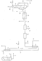
- Figur 1 ein Fließschema einer Ausführungsform des erfindungsgemäßen Verfahrens;
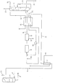
- Figur 2 eine andere Ausführungsform des erfindungsgemäßen Verfahrens.
- Eine Rektifiziersäule 1, welche über eine Zuführungsleitung 2 und eine Abführungsleitung 3 mit einer nichtdargestellten Rektifiziersäule zur Luftzerlegung verbunden ist, dient zur Erzeugung von Rohargon. Das über die
- Leitung 2 zugeführte Gemisch weist eine Zusammensetzung von 88-95% Sauerstoff, 5-12% Argon sowie weniger als 0.1 % Stickstoff auf.
- Das Rohargon wird über eine Leitung 4 mit einem Druck von etwa 1,2 bar vom Kopf der Rohargonsäule 1 entnommen und weist beispielsweise eine Zusammensetzung von 95 Vol.% Argon, 3 Vol.% Sauerstoff und 2 Vol.% Stickstoff auf. Seine Temperatur beträgt beispielsweise 89 K. Das Rohgasgemisch wird einem Verflüssiger 5 zugeführt, in dem das Rohgasgemisch verflüssigt wird. Das verflüssigte Rohgasgemisch wird über eine Leitung 7 6 einem Verdampfer 7 zugeführt. Der Verflüssiger 5 ist oberhalb des Verdampfers 7 angeordnet, so daß das verflüssigte Rohargon am Eingang des Verdampfers einen hydrostatischen Druck von 3 bis 5, vorzugsweise 4 bar aufweist. Dieser hydrostatische Druck entspricht einer Höhendifferenz zwischen Verflüssiger und Verdampfer von ca. 12 m bis 27 m.
- Zur Verdampfung des verflüssigten Rohargons wird dem Verdampfer 7 über eine Leitung 8 Luft oder Stickstoff oder ein Gemisch aus Luft und Stickstoff mit einem Druck von mindestens 7 bzw. 8,5 bar, vorzugsweise 8 bzw. 10 bar. Nach dem Wärmetausch im Verdampfer 7 wird die Luft bzw. der Stickstoff oder das Stickstoff/Luft-Gemisch dem Verflüssiger 5 zugeführt, wo es in Wärmetausch mit dem zu verflüssigenden Rohargon aus Leitung 4 gebracht wird. Vor dem Verflüssiger 5 wird der Luft bzw. dem Stickstoff oder dem Stickstoff/Luft-Gemisch über eine Leitung 9 flüssiger Stickstoff zugemischt.
- Dem dampfförmigen Rohargon wird nach Verlassen des Verdampfers 7 über eine Leitung 10 Wasserstoff zugemischt. Das Gemisch wird einem Reaktor 11 zugeführt, indem der in dem Rohgasgemisch enthaltene Sauerstoff mit dem Wasserstoff zu Wasser reduziert wird. Dem Reaktor 11 ist ausgangsseitig ein Trockner 12 nachgeschaltet in dem das bei der Reaktion gebildete Wasser abgetrennt wird (Leitung 13).
- Der Trockner 12 enthält beispielsweise einen Kühler mit nachfolgendem Wasserabscheider und einen nachfolgenden Adsorber.
- Im Trockner 12 wird über eine Leitung 14 ein Gasgemisch entnommen, das im wesentlichen Argon, Stickstoff sowie gegebenenfalls Wasserstoff enthält, da es sich empfiehlt, vor dem Reaktor 11 Wasserstoff in überstöchiometrischem Verhältnis zuzuführen, um eine restlose Entfernung des Sauersto-fes zu gewährleisten.
- Dieses Gasgemisch wird in einem Wärmetauscher 15 durch Wärmetausch mit Stickstoff (Leitung 16) abgekühlt und mindestens zum Teil verflüssigt Es wird der Sumpfheizung einer Reinargonsäule 17 zugeführt, wo es in Wärmetausch mit flüssigem Sumpfprodukt dieser Säule gebracht wird. Der flüssige Anteil des Gasgemisches wird über eine Leitung 18 in die Reinargonsäule 17 eingedrosselt, die bei einem Druck von etwa 1,6 bar betrieben wird. Der gasförmig verbliebene Anteil des Gasgemisches wird über eine Leitung 19 in die Reinargonsäule 17 eingeleitet. Die Kopfkühlung der Reinargonsäule 17 erfolgt durch flüssigen Stickstoff, der über eine Leitung 20 zugeführt wird.
- In der Reinargonsäule 17 erfolgt eine Rektifikation des Gasgemisches, bei der im Sumpf eine Flüssigkeit gebildet wird, die Argon mit einer Reinheit von etwa 99,999% ent hält. Das flüssige Argon wird über eine Leitung 21 entnommen. Vom Kopf der Reinargonsäule 17 wird über eine Leitung 22 ein Restgas, das im wesentlichen Stickstoff sowie gegebenenfalls Wasserstoff enthält, entnommen.
- Bei dem in Figur 2 dargestellten Verfahren wird das Rohgasgemisch im Gegensatz zu dem Verfahren gemäß Figur 1 in verflüssigtem Zustand aus der Rohargonsäule 1 entnommen. Dadurch entfällt der Verflüssiger 5. Zum Betrieb der Rohargonsäule 1 ist es erforderlich, einen Gasstrom 23 zu entnehmen. Dieser Gasstrom, der im wesentlichen 0"N, und Ar enthält, wird beispielsweise vor dem Luftverdichter der Luftzerlegungsanlage (nicht dargestellt) an die die Rohargonsäule angeschlossen ist, in den Luftstrom eingeleitet
- Figur 2 zeigt außerdem zwei weitere Unterschiede zum Verfahren gemäß Figur 1. Das Rohgasgemisch wird über eine Leitung 24 durch den Wärmetauscher 15 geleitet und erwärmt, vor es dem Reaktor 11 zugeführt wird. Diese Verfahrensweise wird angewendet, wenn der Wärmeinhalt der Luft bzw. des Stickstoffes in Leitung 8 nicht für eine ausreichende Erwärmung des Rohgasgemisches sorgt.
- Der gasförmige Anteil des Gasgemisches, der über Leitung 19 entnommen wird, und der einen hohen Wasserstoffanteil aufweist, wird anstatt direkt in die Reinargonsäule 17 eingeführt, im Wärmetauscher 15 angewärmt und nach Rückverdichtung in einem Gebläse 26 vor dem Reaktor 11 in das Rohgasgemisch rückgeführt (Leitung 25). Auf diese Weise wird der Wasserstoff optimal ausgenutzt. Die über Leitung 22 entnommene Restgasmenge verringert sich entsprechend.
Claims (10)
Applications Claiming Priority (2)
| Application Number | Priority Date | Filing Date | Title |
|---|---|---|---|
| DE3428968 | 1984-08-06 | ||
| DE19843428968 DE3428968A1 (de) | 1984-08-06 | 1984-08-06 | Verfahren und vorrichtung zur zerlegung von rohargon |
Publications (2)
| Publication Number | Publication Date |
|---|---|
| EP0171711A2 true EP0171711A2 (de) | 1986-02-19 |
| EP0171711A3 EP0171711A3 (de) | 1987-08-26 |
Family
ID=6242459
Family Applications (1)
| Application Number | Title | Priority Date | Filing Date |
|---|---|---|---|
| EP85109675A Withdrawn EP0171711A3 (de) | 1984-08-06 | 1985-08-01 | Verfahren und Vorrichtung zur Zerlegung von Rohargon |
Country Status (3)
| Country | Link |
|---|---|
| EP (1) | EP0171711A3 (de) |
| JP (1) | JPS6144279A (de) |
| DE (1) | DE3428968A1 (de) |
Cited By (15)
| Publication number | Priority date | Publication date | Assignee | Title |
|---|---|---|---|---|
| EP0331028A1 (de) * | 1988-03-01 | 1989-09-06 | Linde Aktiengesellschaft | Verfahren zur Reinigung von Rohargon |
| DE4406051A1 (de) * | 1994-02-24 | 1995-08-31 | Linde Ag | Verfahren und Vorrichtung zur Gewinnung von reinem Argon |
| DE4406049A1 (de) * | 1994-02-24 | 1995-09-07 | Linde Ag | Verfahren und Vorrichtung zur Gewinnung von reinem Argon |
| DE4406069A1 (de) * | 1994-02-24 | 1995-09-07 | Linde Ag | Verfahren und Vorrichtung zur Gewinnung von reinem Argon |
| US5590544A (en) * | 1994-02-24 | 1997-01-07 | Linde Aktiengesellschaft | Process and apparatus for recovery of pure argon |
| US5592833A (en) * | 1994-02-24 | 1997-01-14 | Linde Aktiengesellschaft | Process and apparatus for the recovery of pure argon |
| US5644934A (en) * | 1994-12-05 | 1997-07-08 | Linde Aktiengesellchaft | Process and device for low-temperature separation of air |
| EP0628778B2 (de) † | 1993-06-07 | 2001-03-21 | L'air Liquide, Societe Anonyme Pour L'etude Et L'exploitation Des Procedes Georges Claude | Verfahren und Hochdruckgasversorgungseinheit für eine ein Luftbestandteil verbrauchende Anlage |
| FR2848652A1 (fr) * | 2002-12-12 | 2004-06-18 | Air Liquide | Procede et installation de production d'argon |
| DE102007035619A1 (de) | 2007-07-30 | 2009-02-05 | Linde Ag | Verfahren und Vorrichtung zur Gewinnung von Argon durch Tieftemperaturzerlegung von Luft |
| EP2026024A1 (de) | 2007-07-30 | 2009-02-18 | Linde Aktiengesellschaft | Verfahren und Vorrichtung zur Gewinnung von Argon durch Tieftemperaturzerlegung von Luft |
| DE102009016043A1 (de) | 2009-04-02 | 2010-10-07 | Linde Ag | Verfahren zum Betreiben einer Reinargonsäule und Vorrichtung zur Reinargongewinnung |
| WO2014135271A2 (de) | 2013-03-06 | 2014-09-12 | Linde Aktiengesellschaft | Luftzerlegungsanlage, verfahren zur gewinnung eines argon enthaltenden produkts und verfahren zur erstellung einer luftzerlegungsanlage |
| DE102013018664A1 (de) | 2013-10-25 | 2015-04-30 | Linde Aktiengesellschaft | Verfahren zur Tieftemperaturzerlegung von Luft und Tieftemperatur-Luftzerlegungsanlage |
| EP3040665A1 (de) | 2014-12-30 | 2016-07-06 | Linde Aktiengesellschaft | Destillationssäulen-system und anlage zur erzeugung von sauerstoff durch tieftemperaturzerlegung von luft |
Families Citing this family (1)
| Publication number | Priority date | Publication date | Assignee | Title |
|---|---|---|---|---|
| DE3840506A1 (de) * | 1988-12-01 | 1990-06-07 | Linde Ag | Verfahren und vorrichtung zur luftzerlegung |
Family Cites Families (3)
| Publication number | Priority date | Publication date | Assignee | Title |
|---|---|---|---|---|
| DE2325422A1 (de) * | 1973-05-18 | 1974-12-05 | Linde Ag | Verfahren und vorrichtung zur zerlegung von rohargon |
| GB2061478B (en) * | 1979-10-23 | 1983-06-22 | Air Prod & Chem | Method and cryogenic plant for producing gaseous oxygen |
| JPS5697774A (en) * | 1979-12-29 | 1981-08-06 | Nippon Oxygen Co Ltd | Method of sampling argon in air separator |
-
1984
- 1984-08-06 DE DE19843428968 patent/DE3428968A1/de not_active Withdrawn
-
1985
- 1985-08-01 EP EP85109675A patent/EP0171711A3/de not_active Withdrawn
- 1985-08-05 JP JP17224385A patent/JPS6144279A/ja active Pending
Cited By (15)
| Publication number | Priority date | Publication date | Assignee | Title |
|---|---|---|---|---|
| EP0331028A1 (de) * | 1988-03-01 | 1989-09-06 | Linde Aktiengesellschaft | Verfahren zur Reinigung von Rohargon |
| EP0628778B2 (de) † | 1993-06-07 | 2001-03-21 | L'air Liquide, Societe Anonyme Pour L'etude Et L'exploitation Des Procedes Georges Claude | Verfahren und Hochdruckgasversorgungseinheit für eine ein Luftbestandteil verbrauchende Anlage |
| DE4406051A1 (de) * | 1994-02-24 | 1995-08-31 | Linde Ag | Verfahren und Vorrichtung zur Gewinnung von reinem Argon |
| DE4406049A1 (de) * | 1994-02-24 | 1995-09-07 | Linde Ag | Verfahren und Vorrichtung zur Gewinnung von reinem Argon |
| DE4406069A1 (de) * | 1994-02-24 | 1995-09-07 | Linde Ag | Verfahren und Vorrichtung zur Gewinnung von reinem Argon |
| US5590544A (en) * | 1994-02-24 | 1997-01-07 | Linde Aktiengesellschaft | Process and apparatus for recovery of pure argon |
| US5592833A (en) * | 1994-02-24 | 1997-01-14 | Linde Aktiengesellschaft | Process and apparatus for the recovery of pure argon |
| US5644934A (en) * | 1994-12-05 | 1997-07-08 | Linde Aktiengesellchaft | Process and device for low-temperature separation of air |
| FR2848652A1 (fr) * | 2002-12-12 | 2004-06-18 | Air Liquide | Procede et installation de production d'argon |
| DE102007035619A1 (de) | 2007-07-30 | 2009-02-05 | Linde Ag | Verfahren und Vorrichtung zur Gewinnung von Argon durch Tieftemperaturzerlegung von Luft |
| EP2026024A1 (de) | 2007-07-30 | 2009-02-18 | Linde Aktiengesellschaft | Verfahren und Vorrichtung zur Gewinnung von Argon durch Tieftemperaturzerlegung von Luft |
| DE102009016043A1 (de) | 2009-04-02 | 2010-10-07 | Linde Ag | Verfahren zum Betreiben einer Reinargonsäule und Vorrichtung zur Reinargongewinnung |
| WO2014135271A2 (de) | 2013-03-06 | 2014-09-12 | Linde Aktiengesellschaft | Luftzerlegungsanlage, verfahren zur gewinnung eines argon enthaltenden produkts und verfahren zur erstellung einer luftzerlegungsanlage |
| DE102013018664A1 (de) | 2013-10-25 | 2015-04-30 | Linde Aktiengesellschaft | Verfahren zur Tieftemperaturzerlegung von Luft und Tieftemperatur-Luftzerlegungsanlage |
| EP3040665A1 (de) | 2014-12-30 | 2016-07-06 | Linde Aktiengesellschaft | Destillationssäulen-system und anlage zur erzeugung von sauerstoff durch tieftemperaturzerlegung von luft |
Also Published As
| Publication number | Publication date |
|---|---|
| EP0171711A3 (de) | 1987-08-26 |
| DE3428968A1 (de) | 1986-02-13 |
| JPS6144279A (ja) | 1986-03-03 |
Similar Documents
| Publication | Publication Date | Title |
|---|---|---|
| EP0299364B1 (de) | Verfahren und Vorrichtung zur Luftzerlegung durch Rektifikation | |
| EP0331028B1 (de) | Verfahren zur Reinigung von Rohargon | |
| EP0377117B1 (de) | Verfahren und Vorrichtung zur Luftzerlegung | |
| EP0171711A2 (de) | Verfahren und Vorrichtung zur Zerlegung von Rohargon | |
| DE69214409T3 (de) | Verfahren zur Herstellung unreinen Sauerstoffs | |
| DE2535132C3 (de) | Verfahren und Vorrichtung zur Herstellung von Drucksauerstoff durch zweistufige Tieftemperaturrektifikation von Luft | |
| DE2920270C2 (de) | Verfahren zum Erzeugen von Sauerstoff | |
| DE69302064T3 (de) | Destillationsprozess für die Herstellung von kohlenmonoxidfreiem Stickstoff | |
| DE69004994T3 (de) | Lufttrennung. | |
| DE69209572T2 (de) | Verfahren zur Herstellung von reinstem Stickstoff | |
| EP0100923A1 (de) | Verfahren und Vorrichtung zur Zerlegung eines Gasgemisches | |
| DE69900516T2 (de) | Verfahren und Anlage zur kombinierter Herstellung einer Ammoniak-Synthesemischung und Kohlenmonoxyd | |
| EP0948730A1 (de) | Verfahren und vorrichtung zur gewinnung von druckstickstoff | |
| DE3817244A1 (de) | Verfahren zur tieftemperaturzerlegung von luft | |
| DE3307181C2 (de) | ||
| DE69520134T2 (de) | Verfahren und Vorrichtung zum Verdichten eines zu destillierenden Gasgemisches und zum Entspannen wenigstens eines Gasstromes | |
| DE2903089A1 (de) | Verfahren zur gewinnung von sauerstoff aus luft | |
| EP0313883B1 (de) | Verfahren zur Wasserstoff-Kohlenmonoxid-Zerlegung mittels partieller Kondensation bei tiefer Temperatur | |
| DE1135935B (de) | Verfahren und Vorrichtung zur Gewinnung von Sauerstoff geringer Reinheit durch Tieftemperatur-Luftzerlegung | |
| DE3035844A1 (de) | Verfahren und vorrichtung zur gewinnung von sauerstoff mittlerer reinheit | |
| DE19636306A1 (de) | Verfahren und Vorrichtung zur Gewinnung von Argon durch Tieftemperaturzerlegung von Luft | |
| DE1041989B (de) | Verfahren und Einrichtung zur Gaszerlegung, vorzugsweise Luftzerlegung, mittels Tieftemperaturrektifikation | |
| DE3814187A1 (de) | Verfahren zur luftzerlegung durch tieftemperaturrektifikation | |
| EP0559117B1 (de) | Verfahren und Vorrichtung zur Zerlegung eines Gasgemisches | |
| EP0834711A2 (de) | Verfahren und Vorrichtung zur Gewinnung von hochreinem Stickstoff |
Legal Events
| Date | Code | Title | Description |
|---|---|---|---|
| PUAI | Public reference made under article 153(3) epc to a published international application that has entered the european phase |
Free format text: ORIGINAL CODE: 0009012 |
|
| AK | Designated contracting states |
Designated state(s): AT DE FR GB IT NL SE |
|
| PUAL | Search report despatched |
Free format text: ORIGINAL CODE: 0009013 |
|
| AK | Designated contracting states |
Kind code of ref document: A3 Designated state(s): AT DE FR GB IT NL SE |
|
| STAA | Information on the status of an ep patent application or granted ep patent |
Free format text: STATUS: THE APPLICATION IS DEEMED TO BE WITHDRAWN |
|
| 18D | Application deemed to be withdrawn |
Effective date: 19880227 |
|
| RIN1 | Information on inventor provided before grant (corrected) |
Inventor name: SCHOENPFLUG, EUGEN, DIPL.-ING. Inventor name: KOENNING, HEINRICH, ING. GRAD. |