EP2961244B1 - Gargerät - Google Patents
Gargerät Download PDFInfo
- Publication number
- EP2961244B1 EP2961244B1 EP15173251.8A EP15173251A EP2961244B1 EP 2961244 B1 EP2961244 B1 EP 2961244B1 EP 15173251 A EP15173251 A EP 15173251A EP 2961244 B1 EP2961244 B1 EP 2961244B1
- Authority
- EP
- European Patent Office
- Prior art keywords
- cooking chamber
- frequency
- cooking
- damping
- chamber door
- Prior art date
- Legal status (The legal status is an assumption and is not a legal conclusion. Google has not performed a legal analysis and makes no representation as to the accuracy of the status listed.)
- Active
Links
Images

Classifications
-
- H—ELECTRICITY
- H05—ELECTRIC TECHNIQUES NOT OTHERWISE PROVIDED FOR
- H05B—ELECTRIC HEATING; ELECTRIC LIGHT SOURCES NOT OTHERWISE PROVIDED FOR; CIRCUIT ARRANGEMENTS FOR ELECTRIC LIGHT SOURCES, IN GENERAL
- H05B6/00—Heating by electric, magnetic or electromagnetic fields
- H05B6/64—Heating using microwaves
- H05B6/76—Prevention of microwave leakage, e.g. door sealings
- H05B6/763—Microwave radiation seals for doors
Definitions
- the present invention relates to a cooking appliance with at least one housing device and at least one heatable by at least one heater cooking chamber, wherein the heater comprises at least one high-frequency generator and wherein the cooking chamber for introducing food has at least one cooking chamber opening which is closed by at least one cooking chamber door, wherein the cooking chamber door is assigned at least one high-frequency damping device which seals at least one remaining between the housing device and the closed cooking chamber gap against the escape of high frequency radiation from the cooking chamber and the at least two damping elements, and wherein the housing means in the cooking chamber opening at least partially has an inclined contact portion , Which has an angle to the depth extent of the cooking chamber, which is greater than 0 ° and less than 90 °, and that the cooking space in closed Side facing the cooking chamber door ssenen state comprises a sealing portion which is adapted to the inclined contact portion of the housing device characterized in that the inlet regions of the damping elements of the high-frequency damping device extending substantially parallel to the contact portion of the cooking chamber.
- high-frequency radiation is introduced into the cooking chamber for cooking food.
- the cooking chamber opening can be closed with a door, which itself substantially does not transmit high-frequency radiation.
- the remaining gap between the housing of the cooking appliance and the closed cooking chamber door is usually sealed radiation-safe with a high-frequency gasket in the form of a lambda / 4-trap.
- the radiation entering the gap then enters the lambda / 4 trap and is extinguished in it.
- a disadvantage of such high-frequency seals is that an optimal seal only works in a very specific wavelength range.
- a lambda / 4 trap is dimensioned such that it has a length of approximately one quarter of the wavelength of the high-frequency radiation used. Dodge the However, if the wavelength radiated differs from the design of the lambda / 4 trap, not all of the radiation may be shielded from the frequency selective seal.
- Cooking appliances of the type mentioned are, for example, from the JP 2005 249267 A known.
- the DE 195 79 28 A1 discloses a microwave working space with a conical door whose contact surface with the working space consists of a plastic material with a flexible metal surface.
- the cooking appliance according to the invention has at least one housing device and at least one cooking chamber which can be heated by means of at least one heating device.
- the heating device comprises at least one high frequency generator and the cooking chamber has at least one cooking chamber opening for introducing food to be cooked.
- the cooking chamber opening can be closed by means of at least one cooking chamber door.
- the cooking chamber door is associated with at least one high-frequency damping device which seals at least one gap remaining between the housing device and the closed cooking chamber against the escape of high-frequency radiation from the cooking chamber and which comprises at least two damping elements.
- the housing device has, at least in sections, an oblique contact section.
- the side of the cooking chamber door facing the cooking chamber in the closed state comprises a sealing section which is adapted to this oblique contact section in that the entry regions of the damping elements of the high-frequency damping device extend substantially parallel to the contact section of the cooking chamber.
- the distance and / or the alignment between the high-frequency damping device and the contact region of the housing device can be adjusted. So can a more even Gap between the closed cooking chamber door and the housing device can be achieved.
- the distance and / or the alignment between the high-frequency damping device and the abutment region of the housing device can preferably be set via at least one screw connection.
- the high-frequency damping device is preferably movable or adjustable z. B. added to a frame part of the cooking chamber door.
- the high-frequency damping device can be adapted to fit the system section of the housing device. As a result, a particularly reliable shielding of the cooking chamber is achieved with respect to the environment.
- the distance and / or the alignment between the high-frequency damping device and the abutment region of the housing device can also be adjusted in a self-adjusting manner by means of at least one pretensioning device in advantageous developments.
- the high-frequency damping device is particularly preferably resiliently or easily floating added to the cooking chamber door, wherein the high-frequency damping device automatically applies when closing the door to the inclined contact portion of the housing device.
- the cooking appliance according to the invention is designed in particular as a microwave oven or as a microwave.
- the cooking appliance according to the invention can also be designed as a Kombigar réelle, in which the heating device comprises at least one further heat source in addition to a high-frequency generator.
- Such a combination device can, for. B. be designed as an oven, which is then designed for a convection, top and bottom heat and microwave operation.
- the individual heat sources of the heater can be used individually or in combination.
- the high-frequency damping device on the cooking chamber door is preferably configured in such a way that, when the cooking chamber door is closed, it provides a gasket opening which essentially completely surrounds the cooking chamber opening.
- the damping elements of the high-frequency damping device form a kind of comb or a comb structure and provide a plurality of damping sections in the high-frequency damping device.
- oblique means in particular also inclined, the oblique contact section and the sealing section adapted thereto in particular not being arranged at an angle of 90 ° to the front of the device, but at least slightly deviating therefrom angularly.
- the cooking appliance according to the invention offers many advantages.
- a considerable advantage is that a high-frequency damping device with at least two damping elements can be used by the oblique configuration of the cooking chamber opening and the matching Garraumt without the space of the cooking appliance must be substantially increased or the available cooking space must be reduced.
- the high-frequency damping device is provided at the oblique sealing portion of the cooking chamber door, whereby the high-frequency damping device is not provided longitudinally or transversely on the door, but is also inclined. This allows a particularly small design of the cooking device, in which the size of the cooking chamber is not significantly limited.
- the high-frequency damping device comprises at least two wave traps, which are each formed by at least one damping element at least in sections.
- a high-frequency damping device is provided which allows a particularly good sealing of the gap between the closed cooking chamber door and the housing device. This is particularly advantageous when the high-frequency generator generates high-frequency radiation in a specific frequency band and not the entire high-frequency radiation is extinguished by a first wave trap.
- the damping sections provided by the individual damping elements or the individual wave traps work essentially analogously to known lambda / 4 traps by shaft extinction.
- the length of the wave traps does not have to be lambda / 4, but may also deviate upward and particularly preferably downward.
- the substantially complete radiation is intercepted by the high-frequency damping device through the entirety of the damping elements provided or through the damping sections.
- the extinction takes place by an interaction of the individual wave traps or damping sections.
- the high-frequency damping device or the wave traps are then preferably of the basic structure similar to known lambda / 4 traps.
- at least one cooking chamber opening with the door closed essentially circumferential channel is provided, which is in particular at least partially made of a radiopaque material.
- the at least two damping elements are arranged at least in sections and thus form the wave traps.
- the channel is then preferably also formed at least in sections by the damping elements.
- the channel preferably has at least two openings through which high-frequency radiation from the gap between the cooking chamber door and the housing device can penetrate into the high-frequency damping device.
- the abutment portion of the housing device and / or the sealing portion of the cooking chamber door are formed at least partially substantially funnel-shaped.
- this funnel-shaped configuration is provided in particular such that the funnel shape tapers into the cooking appliance.
- the contact section of the housing device is provided along the entire cooking chamber opening and the sealing section of the cooking chamber door is designed accordingly. As a result, the escape of high-frequency radiation from the cooking chamber through the gap between the cooking chamber door and the housing device is avoided in a particularly effective manner.
- the high-frequency damping device is an integral part of the cooking chamber door. Then, the high-frequency damping device is not visible as a separate part and so from the outside substantially not recognized by the user.
- the high-frequency damping device preferably has at least one cover element.
- a cover is preferably radiolucent and can, for. B. may be formed as a silicone gasket, which in particular substantially completely fills the gap between the cooking chamber door and the housing device when the cooking chamber door is closed and preferably provides a certain seal between the cooking chamber and the environment. For example, the escape of moisture through the door gap can be avoided.
- the cover member has a rib structure, which can contribute to the alignment and stabilization of the damping elements.
- the cover preferably covers the individual damping elements visually appealing, so that the high-frequency damping device can be integrated inconspicuously in the cooking chamber door.
- the damping elements of the high-frequency damping device are arranged substantially one behind the other.
- the orientation starting from the cooking space along the inclined contact area to the outside is to be understood in particular behind one another.
- a plurality of successively arranged wave traps are provided, which in particular also cancel out different frequency ranges of the high-frequency radiation generated by a high-frequency generator.
- the high-frequency damping device comprises at least four damping elements.
- a high-frequency damping device with four successively arranged wave traps is provided which ensure a reliable seal even with a broadly emitted frequency band of high-frequency radiation.
- the length of the wave trap can be understood as the length of the attenuation sections, the length of the attenuation elements of the wave trap preferably being adapted to the frequencies or wavelengths of the high-frequency radiation generated by the high frequency generator.
- a cooking appliance as described above may preferably also damp a very large radiation spectrum.
- the frequency of the high-frequency radiation can then also lie, for example, outside the ISM band, without there being any escape of radiation from the cooking chamber.
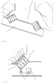
- FIG. 1 is a purely schematic representation of an inventive cooking appliance 1 is shown in a perspective view, wherein the cooking appliance 1 is designed here as a microwave oven 100.
- the cooking appliance 1 has a housing 2, in which a substantially parallelepiped cooking space 3 with cooking space walls 4 is provided.
- a cooking chamber opening 6 of the cooking chamber 3 can be closed by a cooking chamber door 7.
- the cooking chamber 3 can be heated by means of a heating device, wherein the heating device in the exemplary embodiment shown here comprises only one high-frequency generator 5.
- High-frequency radiation 10 can be introduced into the cooking chamber 3 via the high-frequency generator 5, as a result of which food introduced into the cooking chamber 3 can be heated or cooked.
- the heating device may also include a plurality of high frequency generator 5 or other heating sources, with which the cooking chamber 3 can also be heated thermally.
- a Kombigarêt can in addition to a microwave operation z.
- circulating air or a hot air operation can be provided, the various modes can be used individually or in combination.
- the cooking chamber door 7 has a viewing window 20, which here in the embodiment shown here, an outer pane 21, an inner pane 22, a perforated plate 23 and a purely in FIG. 4 indicated frame construction includes.
- the perforated plate 23 serves to seal the cooking chamber 3 in the region of the viewing window 20 against high-frequency radiation.
- the holes in the perforated plate 23 are suitably small-sized in accordance with the wavelength or frequency of the high-frequency radiation used.
- the cooking appliance 1 also has a control panel 24, which comprises a display device 25 and a plurality of operating elements 26. Via the operating elements 26, various parameters and operating modes for a cooking process can be set. About as a display 27 In the case of a display device 25, a user can be informed about various properties of the cooking appliance and about the progress of the cooking process.
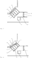
- FIG. 2 the cooking appliance according to the invention is shown in a purely schematic sectional view from above in the cooking chamber opening 6.
- the cooking chamber 3 in the region of the cooking chamber opening 6 has an inclined contact section 11, to which the sealing section 13 of the cooking chamber door 7 is adapted on the side 12 facing the cooking chamber 3. Sloping means that this section has an angle ⁇ to the depth extent (arrow z) of the cooking chamber, which is greater than 0 ° and smaller than 90 °. It is particularly advantageous if the angle is between 15 ° and 40 °.
- the high-frequency damping device 8 is provided to seal the gap 9 between the cooking chamber door 7 and the housing device 2 with closed cooking chamber door 7 against high-frequency radiation 10.
- the high-frequency damping device 8 comprises a plurality of, in the embodiment shown here four damping elements 14, which is formed by four so-called wave traps 15 to eliminate passing through the gap 9 high-frequency radiation 10 by extinction.
- the structure of the individual wave traps 15 corresponds to the structure of the prior art known lambda / 4 traps.
- inlet regions are provided which extend to the gap 9 and thus also to the contact section 11.
- a damping portion 19 extends in the form of a labyrinth-shaped here channel 28, the electromagnetically effective length is less than a quarter of the wavelength of the incoming high-frequency radiation.
- four successively arranged channels 28 are provided, each having an entrance slit 29.
- the inlet regions are likewise arranged one behind the other and thus on a line which extends substantially parallel to the abutment section 11 of the cooking chamber 3.
- the arrangement of several wave traps 15 in a row provides a particularly secure foreclosure of the cooking chamber 3 against exiting high frequency radiation 10.
- one or more wave traps 15 ensure that the entire in the Gap 9 entering high-frequency radiation 10 is eliminated by the wave traps 15. This can be advantageous in particular when a wide spectrum of high-frequency radiation is introduced into the cooking chamber 3 by the high-frequency generator 5.
- the inclined arrangement of the high-frequency damping device 8 ensures that a plurality of shaft traps 15 can be provided one behind the other for sealing the cooking chamber 3, without significantly increasing the space of the cooking chamber door 7 or that the usable cooking space size is reduced.
- the funnel-shaped configuration of the abutment portion 11 and the sealing portion 13 has advantages in adjusting the gap 9 between the closed cooking chamber door 7 and the abutment portion 11.
- FIG. 3 is the view according to FIG. 2 shown with a slightly open cooking chamber door 7. Again, the substantially funnel-shaped configuration of the cooking chamber opening 6 can be seen through the obliquely formed contact portion 11.
- FIG. 4 shows purely schematically an enlarged detail of the sealing portion 13 of the cooking chamber door 7 at the abutment portion 11 of the housing device 2. It can be seen that the sealing portion 13 is substantially completely provided by the high-frequency damping device 8, wherein the remaining gap 9 between the housing device 2 and the cooking chamber door 7 is filled in the embodiment shown here by a cover 16.
- the cover element 16 is embodied here as a silicone seal 31 and seals the remaining gap 9 substantially dense but permeable to radiation.
- High-frequency radiation 10 from the cooking chamber 3 can pass through the gap 9 and the cover element 16 into one or more wave traps 15 through the corresponding entrance gaps 29, where the high-frequency radiation 10 is extinguished. As a result, a reliable high-frequency sealing of the cooking chamber 3 is achieved.
- the cover 16 has a rib structure 36, with which a stabilization and alignment of the individual damping elements can be achieved.
- the cover 16 it is achieved by the cover 16 that the high-frequency damping device 8 can be concealed visually appealing.
- the high-frequency damping device 8 is received on the cooking chamber door 7 via two screw connections 17.
- the screw 17 are fixed on one side to a frame part 30 of the cooking chamber door 7 and connected to the other side with the high-frequency damping device 8.
- the distance and / or the alignment between the high-frequency damping device 8 and the contact area 11 of the housing device 2 can be adjusted.
- an optimal alignment of sealing portion 13 and contact portion 11 can always be ensured to each other.
- the substantially funnel-shaped configuration of the two sections is advantageous.
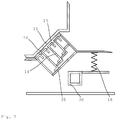
- FIG. 5 Another embodiment is in FIG. 5 shown purely schematically. Also in FIG. 5 an enlarged detail of a sealing portion 13 of the cooking chamber door 7 at a contact portion 11 of the housing device 2 is shown.
- the high-frequency damping device 8 by means of a biasing device 18, which is designed here as a spring 32, stored. Due to the sprung mounting and the funnel-shaped configuration of the sealing section 13 and contact section 11, the high-frequency damping device 8 is accommodated in a self-adjusting manner on the cooking chamber door 7 or on the cooking appliance 1.
- the oblique sealing portion 13 is guided along the oblique or funnel-shaped abutment portion 11 of the housing device 2, wherein the high-frequency damping device 8 self-aligning when closing the door by the spring-mounted storage in the optimum position.
- the high-frequency damping device 8 self-aligning when closing the door by the spring-mounted storage in the optimum position.
- the high-frequency damping device 8 is received in the embodiment shown here on the inner pane 22 of the cooking chamber door 7.
- the spring-mounted storage takes place via a biasing device 18, which connects the inner disc 22 with a housing part 33.
- the high-frequency damping device 8 can also be directly by means of a biasing device 18 z. B. are connected to a frame part 30 of the cooking chamber door 7.
- FIGS. 6 and 7 is in each case an embodiment according to FIG. 5 shown purely schematically, wherein in the FIGS. 6 and 7 representations shown four damping elements 14 in the high-frequency damping device 8, the damping sections 19 have different lengths.
- the damping elements 14, also referred to as choke, are dimensioned differently long, whereby they each provide a different damping section 19 available.
- Conventional lambda / 4 traps generally have attenuation sections with a length of one quarter of the wavelength of the high-frequency radiation 10 to be attenuated.
- the wave traps 15 may be advantageous for the wave traps 15 to have attenuation sections 19 of different lengths. This may be advantageous, for example, if not exactly one wavelength, but high-frequency radiation 10 of a certain bandwidth is introduced into the cooking chamber.
- the damping portions 19 according to the invention not necessarily have a length of lambda / 4.
- the damping sections can preferably also be shorter or longer. An extinction of the radiation is then effected by an interaction of the individual wave traps 15.
- An advantageous embodiment of the individual wave traps 15 for specific wavelengths or wavelength ranges can be simulated and then easily implemented.
- the cooking appliance 1 according to the invention with a high-frequency attenuation device 8 with several wave traps 15 can also attenuate a very large radiation spectrum.
- the frequency of the high-frequency radiation can then also lie, for example, outside the ISM band, without there being any escape of radiation from the cooking chamber.
Landscapes
- Physics & Mathematics (AREA)
- Electromagnetism (AREA)
- Electric Ovens (AREA)
- Constitution Of High-Frequency Heating (AREA)
Priority Applications (1)
| Application Number | Priority Date | Filing Date | Title |
|---|---|---|---|
| PL15173251T PL2961244T3 (pl) | 2014-06-25 | 2015-06-23 | Urządzenie do gotowania |
Applications Claiming Priority (1)
| Application Number | Priority Date | Filing Date | Title |
|---|---|---|---|
| DE102014108855.7A DE102014108855A1 (de) | 2014-06-25 | 2014-06-25 | Gargerät |
Publications (2)
| Publication Number | Publication Date |
|---|---|
| EP2961244A1 EP2961244A1 (de) | 2015-12-30 |
| EP2961244B1 true EP2961244B1 (de) | 2017-08-09 |
Family
ID=53488206
Family Applications (1)
| Application Number | Title | Priority Date | Filing Date |
|---|---|---|---|
| EP15173251.8A Active EP2961244B1 (de) | 2014-06-25 | 2015-06-23 | Gargerät |
Country Status (4)
| Country | Link |
|---|---|
| EP (1) | EP2961244B1 (pl) |
| DE (1) | DE102014108855A1 (pl) |
| ES (1) | ES2643395T3 (pl) |
| PL (1) | PL2961244T3 (pl) |
Family Cites Families (6)
| Publication number | Priority date | Publication date | Assignee | Title |
|---|---|---|---|---|
| CA1054231A (en) * | 1975-03-31 | 1979-05-08 | Arnold M. Bucksbaum | Microwave oven door seal system of resonant transmission line structure |
| JP2851118B2 (ja) * | 1990-03-29 | 1999-01-27 | 株式会社東芝 | 高周波加熱装置 |
| JPH0815117B2 (ja) * | 1993-06-28 | 1996-02-14 | 川重防災工業株式会社 | 誘電加熱装置のシール構造 |
| JP2005249267A (ja) * | 2004-03-03 | 2005-09-15 | Sanyo Electric Co Ltd | 電子レンジ |
| DE102006042992A1 (de) * | 2006-09-13 | 2008-04-03 | BSH Bosch und Siemens Hausgeräte GmbH | Mikrowellenfalle |
| JP5845431B2 (ja) * | 2010-07-16 | 2016-01-20 | パナソニックIpマネジメント株式会社 | 高周波加熱装置 |
-
2014
- 2014-06-25 DE DE102014108855.7A patent/DE102014108855A1/de not_active Withdrawn
-
2015
- 2015-06-23 ES ES15173251.8T patent/ES2643395T3/es active Active
- 2015-06-23 PL PL15173251T patent/PL2961244T3/pl unknown
- 2015-06-23 EP EP15173251.8A patent/EP2961244B1/de active Active
Non-Patent Citations (1)
| Title |
|---|
| None * |
Also Published As
| Publication number | Publication date |
|---|---|
| EP2961244A1 (de) | 2015-12-30 |
| ES2643395T3 (es) | 2017-11-22 |
| DE102014108855A1 (de) | 2015-12-31 |
| PL2961244T3 (pl) | 2017-12-29 |
Similar Documents
| Publication | Publication Date | Title |
|---|---|---|
| EP2966935B1 (de) | Gargerät und befestigungssystem | |
| EP2469177A1 (de) | Gargerät | |
| EP2747515A1 (de) | Gargerät | |
| AT398875B (de) | Hochfrequenz-heizgerät | |
| EP2961244B1 (de) | Gargerät | |
| DE3607557C2 (pl) | ||
| EP3225079B1 (de) | Haushaltsgargerät | |
| DE3029648A1 (de) | Mikrowellenheizvorrichtung | |
| EP2950617B1 (de) | Gargerät mit mikrowellendichtung | |
| EP4473798A1 (de) | Haushalts-mikrowellengargerät | |
| DE102009026932A1 (de) | Dichtung und Hausgerät zum Zubereiten von Lebensmitteln mit einer derartigen Dichtung | |
| BE1030443B1 (de) | Gargerät, umfassend einen Garraum und eine Kamera zur Beobachtung des Garraums, sowie Verfahren zum Betrieb des Gargeräts | |
| DE102004003406A1 (de) | Garofen | |
| DE102006042992A1 (de) | Mikrowellenfalle | |
| DE102014112592A1 (de) | Gargerät | |
| EP3209094B1 (de) | Gargerät | |
| DE102023118290B4 (de) | Kombinationsgargerät mit Ringmodenunterdrücker | |
| DE102015102981A1 (de) | Frontblech für ein Gargerät, Baugruppe mit einem Frontblech und einem Gargeräte-Innenkasten sowie Verfahren zur Herstellung der Baugruppe | |
| EP2991451A1 (de) | Gargerät | |
| DE102004052798B4 (de) | Garofen | |
| DE2832914A1 (de) | Mikrowellenbrat- oder backrohr | |
| DE2705983A1 (de) | Mikrowellendichtung fuer kocheinrichtungen | |
| DE3521666C3 (pl) | ||
| DE102014112421A1 (de) | Gargerät | |
| DE7704209U1 (de) | Mikrowellendichtung fuer kocheinrichtungen |
Legal Events
| Date | Code | Title | Description |
|---|---|---|---|
| PUAI | Public reference made under article 153(3) epc to a published international application that has entered the european phase |
Free format text: ORIGINAL CODE: 0009012 |
|
| AK | Designated contracting states |
Kind code of ref document: A1 Designated state(s): AL AT BE BG CH CY CZ DE DK EE ES FI FR GB GR HR HU IE IS IT LI LT LU LV MC MK MT NL NO PL PT RO RS SE SI SK SM TR |
|
| AX | Request for extension of the european patent |
Extension state: BA ME |
|
| 17P | Request for examination filed |
Effective date: 20160704 |
|
| RBV | Designated contracting states (corrected) |
Designated state(s): AL AT BE BG CH CY CZ DE DK EE ES FI FR GB GR HR HU IE IS IT LI LT LU LV MC MK MT NL NO PL PT RO RS SE SI SK SM TR |
|
| GRAP | Despatch of communication of intention to grant a patent |
Free format text: ORIGINAL CODE: EPIDOSNIGR1 |
|
| INTG | Intention to grant announced |
Effective date: 20170330 |
|
| GRAS | Grant fee paid |
Free format text: ORIGINAL CODE: EPIDOSNIGR3 |
|
| GRAA | (expected) grant |
Free format text: ORIGINAL CODE: 0009210 |
|
| AK | Designated contracting states |
Kind code of ref document: B1 Designated state(s): AL AT BE BG CH CY CZ DE DK EE ES FI FR GB GR HR HU IE IS IT LI LT LU LV MC MK MT NL NO PL PT RO RS SE SI SK SM TR |
|
| REG | Reference to a national code |
Ref country code: GB Ref legal event code: FG4D Free format text: NOT ENGLISH |
|
| REG | Reference to a national code |
Ref country code: CH Ref legal event code: EP Ref country code: AT Ref legal event code: REF Ref document number: 918134 Country of ref document: AT Kind code of ref document: T Effective date: 20170815 |
|
| REG | Reference to a national code |
Ref country code: IE Ref legal event code: FG4D Free format text: LANGUAGE OF EP DOCUMENT: GERMAN |
|
| REG | Reference to a national code |
Ref country code: DE Ref legal event code: R096 Ref document number: 502015001617 Country of ref document: DE |
|
| REG | Reference to a national code |
Ref country code: NL Ref legal event code: FP |
|
| REG | Reference to a national code |
Ref country code: ES Ref legal event code: FG2A Ref document number: 2643395 Country of ref document: ES Kind code of ref document: T3 Effective date: 20171122 |
|
| REG | Reference to a national code |
Ref country code: LT Ref legal event code: MG4D |
|
| PG25 | Lapsed in a contracting state [announced via postgrant information from national office to epo] |
Ref country code: FI Free format text: LAPSE BECAUSE OF FAILURE TO SUBMIT A TRANSLATION OF THE DESCRIPTION OR TO PAY THE FEE WITHIN THE PRESCRIBED TIME-LIMIT Effective date: 20170809 Ref country code: LT Free format text: LAPSE BECAUSE OF FAILURE TO SUBMIT A TRANSLATION OF THE DESCRIPTION OR TO PAY THE FEE WITHIN THE PRESCRIBED TIME-LIMIT Effective date: 20170809 Ref country code: NO Free format text: LAPSE BECAUSE OF FAILURE TO SUBMIT A TRANSLATION OF THE DESCRIPTION OR TO PAY THE FEE WITHIN THE PRESCRIBED TIME-LIMIT Effective date: 20171109 Ref country code: HR Free format text: LAPSE BECAUSE OF FAILURE TO SUBMIT A TRANSLATION OF THE DESCRIPTION OR TO PAY THE FEE WITHIN THE PRESCRIBED TIME-LIMIT Effective date: 20170809 Ref country code: SE Free format text: LAPSE BECAUSE OF FAILURE TO SUBMIT A TRANSLATION OF THE DESCRIPTION OR TO PAY THE FEE WITHIN THE PRESCRIBED TIME-LIMIT Effective date: 20170809 |
|
| PG25 | Lapsed in a contracting state [announced via postgrant information from national office to epo] |
Ref country code: BG Free format text: LAPSE BECAUSE OF FAILURE TO SUBMIT A TRANSLATION OF THE DESCRIPTION OR TO PAY THE FEE WITHIN THE PRESCRIBED TIME-LIMIT Effective date: 20171109 Ref country code: RS Free format text: LAPSE BECAUSE OF FAILURE TO SUBMIT A TRANSLATION OF THE DESCRIPTION OR TO PAY THE FEE WITHIN THE PRESCRIBED TIME-LIMIT Effective date: 20170809 Ref country code: IS Free format text: LAPSE BECAUSE OF FAILURE TO SUBMIT A TRANSLATION OF THE DESCRIPTION OR TO PAY THE FEE WITHIN THE PRESCRIBED TIME-LIMIT Effective date: 20171209 Ref country code: LV Free format text: LAPSE BECAUSE OF FAILURE TO SUBMIT A TRANSLATION OF THE DESCRIPTION OR TO PAY THE FEE WITHIN THE PRESCRIBED TIME-LIMIT Effective date: 20170809 Ref country code: GR Free format text: LAPSE BECAUSE OF FAILURE TO SUBMIT A TRANSLATION OF THE DESCRIPTION OR TO PAY THE FEE WITHIN THE PRESCRIBED TIME-LIMIT Effective date: 20171110 |
|
| PG25 | Lapsed in a contracting state [announced via postgrant information from national office to epo] |
Ref country code: CZ Free format text: LAPSE BECAUSE OF FAILURE TO SUBMIT A TRANSLATION OF THE DESCRIPTION OR TO PAY THE FEE WITHIN THE PRESCRIBED TIME-LIMIT Effective date: 20170809 Ref country code: DK Free format text: LAPSE BECAUSE OF FAILURE TO SUBMIT A TRANSLATION OF THE DESCRIPTION OR TO PAY THE FEE WITHIN THE PRESCRIBED TIME-LIMIT Effective date: 20170809 Ref country code: RO Free format text: LAPSE BECAUSE OF FAILURE TO SUBMIT A TRANSLATION OF THE DESCRIPTION OR TO PAY THE FEE WITHIN THE PRESCRIBED TIME-LIMIT Effective date: 20170809 |
|
| REG | Reference to a national code |
Ref country code: DE Ref legal event code: R097 Ref document number: 502015001617 Country of ref document: DE |
|
| PG25 | Lapsed in a contracting state [announced via postgrant information from national office to epo] |
Ref country code: SK Free format text: LAPSE BECAUSE OF FAILURE TO SUBMIT A TRANSLATION OF THE DESCRIPTION OR TO PAY THE FEE WITHIN THE PRESCRIBED TIME-LIMIT Effective date: 20170809 Ref country code: SM Free format text: LAPSE BECAUSE OF FAILURE TO SUBMIT A TRANSLATION OF THE DESCRIPTION OR TO PAY THE FEE WITHIN THE PRESCRIBED TIME-LIMIT Effective date: 20170809 Ref country code: EE Free format text: LAPSE BECAUSE OF FAILURE TO SUBMIT A TRANSLATION OF THE DESCRIPTION OR TO PAY THE FEE WITHIN THE PRESCRIBED TIME-LIMIT Effective date: 20170809 |
|
| PLBE | No opposition filed within time limit |
Free format text: ORIGINAL CODE: 0009261 |
|
| STAA | Information on the status of an ep patent application or granted ep patent |
Free format text: STATUS: NO OPPOSITION FILED WITHIN TIME LIMIT |
|
| REG | Reference to a national code |
Ref country code: FR Ref legal event code: PLFP Year of fee payment: 4 |
|
| 26N | No opposition filed |
Effective date: 20180511 |
|
| PG25 | Lapsed in a contracting state [announced via postgrant information from national office to epo] |
Ref country code: SI Free format text: LAPSE BECAUSE OF FAILURE TO SUBMIT A TRANSLATION OF THE DESCRIPTION OR TO PAY THE FEE WITHIN THE PRESCRIBED TIME-LIMIT Effective date: 20170809 |
|
| PG25 | Lapsed in a contracting state [announced via postgrant information from national office to epo] |
Ref country code: MT Free format text: LAPSE BECAUSE OF FAILURE TO SUBMIT A TRANSLATION OF THE DESCRIPTION OR TO PAY THE FEE WITHIN THE PRESCRIBED TIME-LIMIT Effective date: 20170809 |
|
| REG | Reference to a national code |
Ref country code: CH Ref legal event code: PL |
|
| REG | Reference to a national code |
Ref country code: BE Ref legal event code: MM Effective date: 20180630 |
|
| REG | Reference to a national code |
Ref country code: IE Ref legal event code: MM4A |
|
| PG25 | Lapsed in a contracting state [announced via postgrant information from national office to epo] |
Ref country code: MC Free format text: LAPSE BECAUSE OF FAILURE TO SUBMIT A TRANSLATION OF THE DESCRIPTION OR TO PAY THE FEE WITHIN THE PRESCRIBED TIME-LIMIT Effective date: 20170809 Ref country code: LU Free format text: LAPSE BECAUSE OF NON-PAYMENT OF DUE FEES Effective date: 20180623 |
|
| PG25 | Lapsed in a contracting state [announced via postgrant information from national office to epo] |
Ref country code: CH Free format text: LAPSE BECAUSE OF NON-PAYMENT OF DUE FEES Effective date: 20180630 Ref country code: LI Free format text: LAPSE BECAUSE OF NON-PAYMENT OF DUE FEES Effective date: 20180630 Ref country code: IE Free format text: LAPSE BECAUSE OF NON-PAYMENT OF DUE FEES Effective date: 20180623 |
|
| PG25 | Lapsed in a contracting state [announced via postgrant information from national office to epo] |
Ref country code: BE Free format text: LAPSE BECAUSE OF NON-PAYMENT OF DUE FEES Effective date: 20180630 |
|
| PG25 | Lapsed in a contracting state [announced via postgrant information from national office to epo] |
Ref country code: TR Free format text: LAPSE BECAUSE OF FAILURE TO SUBMIT A TRANSLATION OF THE DESCRIPTION OR TO PAY THE FEE WITHIN THE PRESCRIBED TIME-LIMIT Effective date: 20170809 |
|
| PG25 | Lapsed in a contracting state [announced via postgrant information from national office to epo] |
Ref country code: PT Free format text: LAPSE BECAUSE OF FAILURE TO SUBMIT A TRANSLATION OF THE DESCRIPTION OR TO PAY THE FEE WITHIN THE PRESCRIBED TIME-LIMIT Effective date: 20170809 |
|
| PG25 | Lapsed in a contracting state [announced via postgrant information from national office to epo] |
Ref country code: CY Free format text: LAPSE BECAUSE OF FAILURE TO SUBMIT A TRANSLATION OF THE DESCRIPTION OR TO PAY THE FEE WITHIN THE PRESCRIBED TIME-LIMIT Effective date: 20170809 Ref country code: MK Free format text: LAPSE BECAUSE OF NON-PAYMENT OF DUE FEES Effective date: 20170809 Ref country code: HU Free format text: LAPSE BECAUSE OF FAILURE TO SUBMIT A TRANSLATION OF THE DESCRIPTION OR TO PAY THE FEE WITHIN THE PRESCRIBED TIME-LIMIT; INVALID AB INITIO Effective date: 20150623 |
|
| PG25 | Lapsed in a contracting state [announced via postgrant information from national office to epo] |
Ref country code: AL Free format text: LAPSE BECAUSE OF FAILURE TO SUBMIT A TRANSLATION OF THE DESCRIPTION OR TO PAY THE FEE WITHIN THE PRESCRIBED TIME-LIMIT Effective date: 20170809 |
|
| REG | Reference to a national code |
Ref country code: AT Ref legal event code: MM01 Ref document number: 918134 Country of ref document: AT Kind code of ref document: T Effective date: 20200623 |
|
| PG25 | Lapsed in a contracting state [announced via postgrant information from national office to epo] |
Ref country code: AT Free format text: LAPSE BECAUSE OF NON-PAYMENT OF DUE FEES Effective date: 20200623 |
|
| P01 | Opt-out of the competence of the unified patent court (upc) registered |
Effective date: 20230528 |
|
| PGFP | Annual fee paid to national office [announced via postgrant information from national office to epo] |
Ref country code: NL Payment date: 20240625 Year of fee payment: 10 |
|
| PGFP | Annual fee paid to national office [announced via postgrant information from national office to epo] |
Ref country code: IT Payment date: 20240619 Year of fee payment: 10 |
|
| PGFP | Annual fee paid to national office [announced via postgrant information from national office to epo] |
Ref country code: ES Payment date: 20240710 Year of fee payment: 10 |
|
| REG | Reference to a national code |
Ref country code: DE Ref legal event code: R084 Ref document number: 502015001617 Country of ref document: DE |
|
| PGFP | Annual fee paid to national office [announced via postgrant information from national office to epo] |
Ref country code: DE Payment date: 20250630 Year of fee payment: 11 Ref country code: PL Payment date: 20250520 Year of fee payment: 11 |
|
| PGFP | Annual fee paid to national office [announced via postgrant information from national office to epo] |
Ref country code: GB Payment date: 20250617 Year of fee payment: 11 |
|
| PGFP | Annual fee paid to national office [announced via postgrant information from national office to epo] |
Ref country code: FR Payment date: 20250624 Year of fee payment: 11 |
|
| REG | Reference to a national code |
Ref country code: NL Ref legal event code: MM Effective date: 20250701 |
|
| PG25 | Lapsed in a contracting state [announced via postgrant information from national office to epo] |
Ref country code: NL Free format text: LAPSE BECAUSE OF NON-PAYMENT OF DUE FEES Effective date: 20250701 |