EP2960614B1 - Vorrichtung und verfahren zur schwingungsunterdrückung eines wärmeübertragungsrohrs und dampferzeuger - Google Patents
Vorrichtung und verfahren zur schwingungsunterdrückung eines wärmeübertragungsrohrs und dampferzeuger Download PDFInfo
- Publication number
- EP2960614B1 EP2960614B1 EP13882969.2A EP13882969A EP2960614B1 EP 2960614 B1 EP2960614 B1 EP 2960614B1 EP 13882969 A EP13882969 A EP 13882969A EP 2960614 B1 EP2960614 B1 EP 2960614B1
- Authority
- EP
- European Patent Office
- Prior art keywords
- heat transfer
- support
- support member
- transfer tube
- vibration
- Prior art date
- Legal status (The legal status is an assumption and is not a legal conclusion. Google has not performed a legal analysis and makes no representation as to the accuracy of the status listed.)
- Active
Links
Images


Classifications
-
- F—MECHANICAL ENGINEERING; LIGHTING; HEATING; WEAPONS; BLASTING
- F22—STEAM GENERATION
- F22B—METHODS OF STEAM GENERATION; STEAM BOILERS
- F22B37/00—Component parts or details of steam boilers
- F22B37/02—Component parts or details of steam boilers applicable to more than one kind or type of steam boiler
- F22B37/10—Water tubes; Accessories therefor
- F22B37/20—Supporting arrangements, e.g. for securing water-tube sets
-
- F—MECHANICAL ENGINEERING; LIGHTING; HEATING; WEAPONS; BLASTING
- F22—STEAM GENERATION
- F22B—METHODS OF STEAM GENERATION; STEAM BOILERS
- F22B1/00—Methods of steam generation characterised by form of heating method
- F22B1/02—Methods of steam generation characterised by form of heating method by exploitation of the heat content of hot heat carriers
- F22B1/023—Methods of steam generation characterised by form of heating method by exploitation of the heat content of hot heat carriers with heating tubes, for nuclear reactors as far as they are not classified, according to a specified heating fluid, in another group
- F22B1/025—Methods of steam generation characterised by form of heating method by exploitation of the heat content of hot heat carriers with heating tubes, for nuclear reactors as far as they are not classified, according to a specified heating fluid, in another group with vertical U shaped tubes carried on a horizontal tube sheet
-
- B—PERFORMING OPERATIONS; TRANSPORTING
- B23—MACHINE TOOLS; METAL-WORKING NOT OTHERWISE PROVIDED FOR
- B23P—METAL-WORKING NOT OTHERWISE PROVIDED FOR; COMBINED OPERATIONS; UNIVERSAL MACHINE TOOLS
- B23P15/00—Making specific metal objects by operations not covered by a single other subclass or a group in this subclass
- B23P15/26—Making specific metal objects by operations not covered by a single other subclass or a group in this subclass heat exchangers or the like
-
- F—MECHANICAL ENGINEERING; LIGHTING; HEATING; WEAPONS; BLASTING
- F22—STEAM GENERATION
- F22B—METHODS OF STEAM GENERATION; STEAM BOILERS
- F22B37/00—Component parts or details of steam boilers
- F22B37/02—Component parts or details of steam boilers applicable to more than one kind or type of steam boiler
- F22B37/10—Water tubes; Accessories therefor
- F22B37/20—Supporting arrangements, e.g. for securing water-tube sets
- F22B37/205—Supporting and spacing arrangements for tubes of a tube bundle
- F22B37/206—Anti-vibration supports for the bends of U-tube steam generators
-
- F—MECHANICAL ENGINEERING; LIGHTING; HEATING; WEAPONS; BLASTING
- F28—HEAT EXCHANGE IN GENERAL
- F28D—HEAT-EXCHANGE APPARATUS, NOT PROVIDED FOR IN ANOTHER SUBCLASS, IN WHICH THE HEAT-EXCHANGE MEDIA DO NOT COME INTO DIRECT CONTACT
- F28D7/00—Heat-exchange apparatus having stationary tubular conduit assemblies for both heat-exchange media, the media being in contact with different sides of a conduit wall
- F28D7/16—Heat-exchange apparatus having stationary tubular conduit assemblies for both heat-exchange media, the media being in contact with different sides of a conduit wall the conduits being arranged in parallel spaced relation
- F28D7/1607—Heat-exchange apparatus having stationary tubular conduit assemblies for both heat-exchange media, the media being in contact with different sides of a conduit wall the conduits being arranged in parallel spaced relation with particular pattern of flow of the heat exchange media, e.g. change of flow direction
-
- F—MECHANICAL ENGINEERING; LIGHTING; HEATING; WEAPONS; BLASTING
- F28—HEAT EXCHANGE IN GENERAL
- F28F—DETAILS OF HEAT-EXCHANGE AND HEAT-TRANSFER APPARATUS, OF GENERAL APPLICATION
- F28F9/00—Casings; Header boxes; Auxiliary supports for elements; Auxiliary members within casings
- F28F9/007—Auxiliary supports for elements
- F28F9/013—Auxiliary supports for elements for tubes or tube-assemblies
- F28F9/0132—Auxiliary supports for elements for tubes or tube-assemblies formed by slats, tie-rods, articulated or expandable rods
-
- F—MECHANICAL ENGINEERING; LIGHTING; HEATING; WEAPONS; BLASTING
- F28—HEAT EXCHANGE IN GENERAL
- F28F—DETAILS OF HEAT-EXCHANGE AND HEAT-TRANSFER APPARATUS, OF GENERAL APPLICATION
- F28F2265/00—Safety or protection arrangements; Arrangements for preventing malfunction
- F28F2265/30—Safety or protection arrangements; Arrangements for preventing malfunction for preventing vibrations
Definitions
- the present invention relates to a vibration suppression device and method for heat transfer tubes for suppressing vibration of a plurality of heat transfer tubes used in a heat exchanger, and a steam generator to which the vibration suppression device for heat transfer tubes is applied.
- a nuclear power plant includes a nuclear reactor, a steam turbine, an electric generator, and the like.
- a pressurized water reactor PWR
- the steam generator exchanges heat between the high-temperature and high-pressure water (primary cooling water) and secondary cooling water to generate steam.
- the steam turbine drives a turbine by this steam, and the electric generator generates electricity by this driving power.
- a hollow airtight body portion is provided therein with a tube bundle shroud at a predetermined distance with an inner wall face thereof, a plurality of reverse U-shaped heat transfer tubes are provided in the tube bundle shroud, ends of the heat transfer tubes are supported by a tube sheet, and thus an inlet side channel head and an outlet side channel head of the primary cooling water are formed at a lower end of the body portion.
- an inlet portion of the secondary cooling water is positioned and provided above the tube bundle shroud, a steam-water separator and a moisture separator are vertically arranged, and a steam outlet is formed on the upper side thereof.
- the heat transfer tubes easily vibrate.
- the lower ends of the heat transfer tubes are supported by the tube sheet, intermediate portions are supported by a plurality of tube support plates, and an upper U bend portion is supported by a plurality of anti-vibration bars.
- Each anti-vibration bar is inserted among the transfer tubes to be capable of suppressing vibration of the heat transfer tubes in the out-of-plane direction (stacking direction of the heat transfer tubes) and in-plane direction (longitudinal direction of the heat transfer tubes).
- the anti-vibration bars suppress vibration of the heat transfer tubes in the in-plane direction with friction between the heat transfer tubes and the anti-vibration bars. Therefore, when assembling precision of the heat transfer tubes or the anti-vibration bars is poor, it is difficult to sufficiently suppress the vibration of the heat transfer tubes.
- Patent Literatures To solve such problem, the techniques described in Patent Literatures below have been proposed, for example.
- a heat transfer tube is held by plane parts of upper and lower holding plates.
- a flat plate, a corrugated mounting plate, and a flat plate with a block are used as a support member for a U-shaped portion of a heat transfer tube.
- An U-shaped tube support body with nubs described in Patent Literature 3 holds a tube with tube contact faces of opposed nubs.
- US 2011/146598 discloses a system for retaining boiler tubes.
- EP 2 088 371 discloses a structural framework for supporting the heat exchanger of a steam generator.
- US 2007/089856 discloses a tube support device for a tube bundle.
- the heat exchanger in Patent Literature 1 holds a heat transfer tube by plane parts of upper and lower holding plates.
- the outer surface of the heat transfer tube is supported by two points, which might not sufficiently suppress vibration of the heat transfer tube.
- a heat transfer tube is held by a corrugated mounting plate and a flat plate with a block.
- the U-shaped tube support body with nubs described in Patent Literature 3 holds a tube with tube contact faces of opposed nubs. In these techniques, an outer surface of a heat transfer tube is supported by planes, so that impurities might be deposited onto the contact surface to cause corrosion.
- the present invention aims to solve the above problem, and an object thereof is to provide a vibration suppression device and method for heat transfer tubes, and a steam generator.
- a vibration suppression member for a heat transfer tube includes: a first support member including a first support surface for supporting an outer surface of the heat transfer tube on one surface side; and a second support member including a second support surface and a third support surface which tilt at different predetermined tilt angles relative to the first support surface respectively for supporting the outer surface of the heat transfer tube on one surface side, and another surface of the second support member is fixed to another surface of the first support member.
- the vibration suppression member is formed by fixing the second support member having the second support surface and the third support surface is fixed to the first support member having the first support surface.
- the first support member has a flat plate shape with a predetermined length
- the first support surface is a plane continuously formed on the one surface side
- the second support member extends along a longitudinal direction with a predetermined length and has a plurality of concave parts and a plurality of convex parts which are alternately and continuously formed
- the second support surface and the third support surface are opposed planes relative to the concave part.
- the first support surface is formed by making the first support member into a flat plate shape, and the second support surface and the third support surface are formed by forming the second support member to have concave and convex parts. With this, three support surfaces can easily be formed, whereby the structure can be simplified, and cost can be reduced.
- the concave part and the convex part each has a trapezoidal shape, wherein an orientation of the trapezoidal shape of the concave part and an orientation of the trapezoidal shape of the convex part are opposite to each other.
- the concave parts and the convex parts can easily be formed.
- the plurality of concave parts of the second support member is intermittently fixed to the first support member.
- the first support member and the second support member are intermittently fixed to each other, whereby a local elastic function can be imparted to the support members.
- the heat transfer tube can elastically be supported to appropriately suppress vibration.
- a predetermined gap is formed at a position where the concave part of the second support member and the first support member are not fixed to each other.
- each support member can elastically be deformed by an amount corresponding to the predetermined gap, thereby being capable of elastically supporting the heat transfer tube and appropriately suppressing vibration.
- the concave part of the second support member is fixed to the first support member with a spacer.
- the configuration in which the concave part of the second support member is fixed to the first support member via a spacer can allow all of the plurality of concave parts to have the same shape.
- the manufacture of the second support member is facilitated, whereby the manufacturing process can be simplified and cost can be reduced.
- the second support member includes a plurality of second support member divided units disposed in serial, and each of the second support member divided units being formed such that second concave parts that are not fixed to the first support member are located at both sides of a first concave part that is fixed to the first support member.
- the manufacture of the second support member is facilitated, whereby the manufacturing process can be simplified and cost can be reduced.
- the first support surface, the second support surface, and the third support surface have a pattern capable of holding liquid.
- the contact portion between the heat transfer tube and each of the support members can easily keep a liquid phase state, whereby a damping effect by liquid can easily be produced. Accordingly, the effect of suppressing vibration of heat transfer tubes can well be applied, whereby the vibration of the heat transfer tube can suitably be suppressed.
- the contact portion between the heat transfer tube and each support member can easily keep a liquid phase state, and this can prevent the generation of contamination deposited due to a gas phase state on the contact portion between the heat transfer tube and each support member. Accordingly, troubles such as corrosion of heat transfer tubes caused by contamination can be prevented.
- the pattern is formed by hollowing the support surface.
- the pattern is a dimple having a plurality of dents.
- liquid can suitably be held on each support surface with a simple configuration.
- a manufacturing method of a vibration suppression member for a heat transfer tube includes: preparing a first support member including a first support surface for supporting an outer surface side of the heat transfer tube on one surface; preparing a second support member including a second support surface and a third support surface which tilt at different predetermined tilt angles relative to the first support surface respectively for supporting the outer surface of the heat transfer tube on one surface side; and fixing another surface of the second support member to another surface of the first support member.
- the first support member and the second support member can be manufactured by using a flat plate material having a predetermined length, whereby manufacturing performance can be enhanced, and processing cost can be reduced.
- a plurality of concave parts and a plurality of convex parts are alternately and continuously formed along the longitudinal direction to form the second support surface and the third support surface, and the concave parts are intermittently fixed to the first support member.
- the first support member and the second support member are intermittently fixed to each other, whereby processing cost can be reduced, and the heat transfer tube can elastically be supported to appropriately suppress vibration.
- the first support member and the second support member are fixed by welding.
- a vibration suppression device for heat transfer tubes in which a plurality of heat transfer tube layer is formed by radially arraying a plurality of heat transfer tubes with a predetermined space, a heat transfer tube bundle is formed by stacking the plurality of the heat transfer tube layers, and the heat transfer tube layers adjacent to one another are disposed to shift in an arraying direction, includes a vibration suppression member disposed between the plurality of heat transfer tube layers.
- the vibration suppression member includes a first support member including a first support surface for supporting an outer surface of the heat transfer tube on one surface side, and a second support member including a second support surface and a third support surface which tilt at different predetermined tilt angles relative to the first support surface respectively for supporting the outer surface of the heat transfer tube on one surface side, and another surface of the second support member is fixed to another surface of the first support member.
- each of the heat transfer tubes is supported by the first support surface of the first support member of one of the adjacent vibration suppression member and the second support surface and the third support surface of the second support member of the other adjacent vibration suppression member.
- the radial vibration of the heat transfer tube can be suppressed, whereby the vibration of the heat transfer tube can appropriately be suppressed.
- the first support member has a flat plate shape with a predetermined length
- the first support surface is a plane continuously formed on the one surface side
- the second support member extends along a longitudinal direction with a predetermined length and has a plurality of concave parts and a plurality of convex parts which are alternately and continuously formed
- the second support surface and the third support surface are opposed planes relative to the concave part
- the second support members adjacent to each other in the stacking direction of the heat transfer tube layer are arrayed such that the concave part and the convex part face each other.
- the first support surface is formed by making the first support member into a flat plate shape, and the second support surface and the third support surface are formed by forming the second support member to have concave and convex parts.
- three support surfaces can easily be formed, whereby the structure can be simplified, and cost can be reduced. Therefore, the second support members adjacent to each other in the stacking direction are disposed such that the concave part and the convex part face each other, whereby an elastic function can be imparted to the support members.
- the heat transfer tube can elastically be supported to appropriately suppress vibration.
- the plurality of concave parts of the second support member is intermittently fixed to the first support member, and a predetermined gap is formed at a position where the concave part of the second support member and the first support member are not fixed to each other.
- each support member can elastically be deformed by an amount corresponding to the predetermined gap, thereby being capable of elastically supporting the heat transfer tube and appropriately suppressing vibration.
- the heat transfer tube is supported as being pressed by the first support surface, the second support surface, and the third support surface.
- a mounting position of the heat transfer tube, which is not yet supported as being pressed by the concave part that is not fixed to the first support member is shifted in the direction away from the second support member from a mounting position of the heat transfer tube which is not yet supported as being pressed by the concave part that is fixed to the first support member.
- the plurality of vibration suppression members is connected and held by a plurality of holding members.
- each of the vibration suppression members can be held at an appropriate position to suppress the vibration of the heat transfer tube.
- a vibration suppression method for a vibration suppression device is defined in claim 5.
- This method which applies to heat transfer tubes, in which a plurality of heat transfer tube layer is formed by radially arraying a plurality of heat transfer tubes with a predetermined space, a heat transfer tube bundle is formed by stacking the plurality of the heat transfer tube layers, and the heat transfer tube layers adjacent to one another are disposed to shift in an arraying direction, includes pressing and supporting the heat transfer tube by at least three support surfaces of a vibration suppression member disposed between the heat transfer tube layers.
- a steam generator includes: a body portion having a hollow airtight shape; a heat transfer tube bundle including a plurality of heat transfer tubes, which are disposed in the body portion with a reversed U shape and through which a primary coolant flows; a tube sheet fixed to a lower part of the body portion to support an end of each of the plurality of heat transfer tubes; an inlet side channel head and an outlet side channel head formed at a lower end of the body portion to communicate with an end of each of the plurality of heat transfer tubes; a feed water unit for feeding secondary cooling water into the body portion; a steam outlet formed at an upper end of the body portion; and any one of the above described vibration suppression device for the heat transfer tubes.
- the vibration suppression member is disposed among a plurality of heat transfer tubes.
- each of the heat transfer tubes is supported by the first support surface of the first support member of one of the adjacent vibration suppression member and the second support surface and the third support surface of the second support member of the other adjacent vibration suppression member.
- the vibration suppression member for heat transfer tubes the manufacturing method of a vibration suppression member for heat transfer tubes, the vibration suppression device and method for heat transfer tubes, and the steam generator, the vibration suppression member is formed by fixing the second support member having the second support surface and the third support surface to the first support member having the first support surface. With this configuration, the heat transfer tube is supported by three support surfaces. Thus, the radial vibration of the heat transfer tube can be suppressed, whereby the vibration of the heat transfer tube can appropriately be suppressed.
- FIG. 5 is a schematic diagram illustrating a configuration of a nuclear power plant
- FIG. 6 is a schematic diagram illustrating configuration of a steam generator
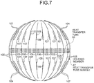
- FIG. 7 is a plan view illustrating a heat transfer tube bundle
- FIG. 8 is a front view of the heat transfer tube bundle
- FIG. 9 is a perspective view illustrating the heat transfer tube bundle.
- a nuclear reactor of the first embodiment is a pressurized water reactor (PWR), in which light water is used as a nuclear reactor coolant and a neutron moderator and is prepared to be high-temperature and high-pressure water that is not boiled throughout a reactor internal portion, the high-temperature and high-pressure water is sent to a steam generator to generate steam by heat exchange, and the steam is sent to a turbine generator to generate electricity.
- PWR pressurized water reactor
- a containment 11 is provided therein with a pressurized water reactor 12 and a steam generator 13, the pressurized water reactor 12 and the steam generator 13 are connected to each other through a high-temperature side supply tube 14 and a low-temperature side supply tube 15, the high-temperature side supply tube 14 is provided with a pressurizer 16, and the low-temperature side supply tube 15 is provided with a primary cooling water pump 17, as illustrated in FIG. 5 .
- the light water is used as the moderator and the primary cooling water (coolant), and in order to suppress boiling of the primary cooling water in the reactor internal portion, a primary cooling system controls to keep a high-pressure state of about 150 to 160 atmospheric pressure by the pressurizer 16.
- the pressurized water reactor 12 the light water as the primary cooling water is heated by low-enriched uranium or MOX as fuel (atomic fuel), and the high-temperature primary cooling water kept at a predetermined high pressure by the pressurizer 16 is sent to the steam generator 13 through the high-temperature side supply tube 14.
- the steam generator 13 heat exchange is performed between the high-temperature and high-pressure primary cooling water and the secondary cooling water, and the cooled primary cooling water returns to the pressurized water reactor 12 through the low-temperature side supply tube 15.
- the steam generator 13 is connected to a steam turbine 32 through a tube 31 that supplies the heated secondary cooling water, that is, the steam, and the tube 31 is provided with a main steam isolation valve 33.
- the steam turbine 32 has a high-pressure turbine 34 and a low-pressure turbine 35, and is connected to an electric generator (power generating device) 36.
- a moisture isolation heater 37 is provided between the high-pressure turbine 34 and the low-pressure turbine 35.
- a cooling water branch tube 38 branched from the tube 31 is connected to the moisture isolation heater 37.
- the high-pressure turbine 34 and the moisture isolation heater 37 are connected through a low-temperature re-heating tube 39, and the moisture isolation heater 37 and the low-pressure turbine 35 are connected through a high-temperature re-heating tube 40.
- the low-pressure turbine 35 of the steam turbine 32 has a condenser 41.
- the condenser 41 is connected to a turbine bypass tube 43 having a bypass valve 42 from the tube 31, and is connected to an intake tube 44 and a drain tube 45 that supply and discharge the cooling water (for example, seawater).
- the intake tube 44 has a circulation water pump 46, and the other end is disposed undersea with the drain tube 45.
- the condenser 41 is connected to a tube 47, and is connected to a condenser pump 48, a grand condenser 49, a condensate demineralizer 50, a condensate booster pump 51, and a low-pressure feed water heater 52.
- the tube 47 is connected to a deaerator 53, and is provided with a main feed water pump 54, a high-pressure feed water heater 55, and a main feed water control valve 56.
- the steam generated by performing heat exchange with the high-temperature and high-pressure primary cooling water is sent to the steam turbine 32 (from the high-pressure turbine 34 to the low-pressure turbine 35) through the tube 31, and the steam turbine 32 is driven by the steam to generate electricity by the electric generator 36.
- the steam from the steam generator 13 drives the high-pressure turbine 34
- the moisture included in the steam is removed and heated by the moisture isolation heater 37, and then, the resultant steam drives the low-pressure turbine 35.
- the steam driving the steam turbine 32 is cooled using seawater by the condenser 41 to be a condensate, and returns to the steam generator 13 through the grand condenser 49, the condensate demineralizer 50, the low-pressure feed water heater 52, the deaerator 53, the high-pressure feed water heater 55, and the like.
- a body portion 61 has an airtight hollow cylindrical shape, and a diameter of the lower part is slightly smaller than that of the upper part as illustrated in FIG. 6 .
- the body portion 61 has a tube bundle shroud 62 having a cylindrical shape with a predetermined gap from an inner wall face at its lower part.
- the tube bundle shroud 62 includes inside a plurality of tube support plates 63 corresponding to a predetermined height position, and a tube sheet 64 fixed under the tube support plate 63, each tube support plate 63 being supported by a plurality of stay rods 65 provided to extend upward from the tube sheet 64.
- the tube bundle shroud 62 is provided therein with a heat transfer tube bundle 67 including a plurality of reverse U-shape heat transfer tubes 66.
- the heat transfer tube bundle 67 has a U bend portion 68 as a U-shape portion at an upper part of each heat transfer tube 66.
- a lower end of each heat transfer tube 66 is expanded and supported by the tube sheet 64, and an intermediate part (a middle part) is supported by the plurality of tube support plates 63.
- the plurality of heat transfer tubes 66 are disposed to be substantially parallel to each other in an inner and outer direction (an up and down direction) of the tube bundle shroud 62, and are disposed to be substantially parallel to each other in a radial direction (a horizontal direction) of the tube bundle shroud 62.
- the lower part of the body portion 61 has a spherical shape, and is provided with an inlet side channel head 71 and an outlet side channel head 72, which are partitioned under the tube sheet 64 by a partition wall 70, and an inlet nozzle 73 and an outlet nozzle 74.
- One end of each heat transfer tube 66 communicates with the inlet side channel head 71, and the other end communicates with the outlet side channel head 72.
- the body portion 61 is provided with a steam-water separator 75 and a moisture separator 76 above the heat transfer tube bundle 67.
- the steam-water separator 75 separates the supply water into steam and hot water
- the moisture separator 76 removes moisture from the separated steam to bring the separated steam into almost dry steam.
- a feed water pipe 77 that supplies secondary cooling water to the inside is connected to the body portion 61 between the heat transfer tube bundle 67 and the steam-water separator 75, and a steam outlet 78 is formed at the top of the body portion 61.
- the secondary cooling water supplied from the feed water pipe 77 to the inside flows down through the tube bundle shroud 62, and then, circulates upward at the tube sheet 64 to move upward in the heat transfer tube bundle 67.
- the secondary cooling water performs heat exchange with the hot water (the primary cooling water) flowing through each heat transfer tube 66.
- the primary cooling water heated in the pressurized water reactor 12 is sent to the inlet side channel head 71 of the steam generator 13 through the high-temperature side supply tube 14, circulates through the plurality of heat transfer tubes 66, and reaches the outlet side channel head 72.
- the secondary cooling water cooled by the condenser 41 is sent to the feed water pipe 77 of the steam generator 13 through the tube 47, and performs heat exchange with the hot water (the primary cooling water) passing through the body portion 61 and flowing in the heat transfer tube 66.
- the body portion 61 heat exchange is performed between the high-temperature and high-pressure primary cooling water and the secondary cooling water, and the cooled primary cooling water returns to the pressurized water reactor 12 through the low-temperature side supply tube 15 from the outlet side channel head 72.
- the secondary cooling water subjected to the heat exchange with the high-pressure and high-temperature primary cooling water moves upward in the body portion 61, and is separated into steam and hot water by the steam-water separator 75.
- the moisture separator 76 removes moisture from this steam, and the resultant steam is sent from the steam outlet 78 to the steam turbine 32 through the tube 31.
- the steam generator 13 configured as described above, when the primary cooling water flows in each of the heat transfer tubes 66, flow-induced vibration is likely to occur at the U bend portion 68.
- the steam generator 13 is provided with a vibration suppression device 100 at the U bend portion 68.
- the U bend portion 68 of the heat transfer tube 66 is disposed at the upper end of the heat transfer tube bundle 67.
- the heat transfer tubes 66 are arrayed such that the heat transfer tube with a larger diameter is sequentially arrayed toward the outermost side from the center to form a heat transfer tube layer.
- This heat transfer tube layers are stacked in a direction orthogonal to the arraying direction of the heat transfer tubes to change the outermost diameter.
- the heat transfer tube bundle 67 having a hemispherical shape at its upper end is formed.
- the vibration suppression device 100 includes a plurality of first anti-vibration members 101 and a second anti-vibration member (vibration suppression member) 102.
- Each of the first anti-vibration members 101 is inserted between the stacked heat transfer tube layers of the heat transfer tubes 66.
- the first anti-vibration member 101 has a rectangular cross-section, and is bent into almost a V shape. The bent part is disposed at the side of the central part of each heat transfer tube 66, and both ends project from the U bend portion 68 of the heat transfer tube 66 with the largest diameter.
- the ends of the first anti-vibration members 101 are disposed in a line along a hemispherical arc of the heat transfer tube bundle 67.
- the first anti-vibration member 101 has a pair of a member with almost a large V shape and a member with a small V shape provided at the inner side of the member with almost a large V shape. Three pairs are disposed on the semicircular portion of the heat transfer tubes 66, for example.
- the first anti-vibration member 101 is made of a metal material (e.g., stainless 405 or stainless 410) preferable for suppressing vibration of the heat transfer tube 66.
- the second anti-vibration member 102 is inserted between the stacked heat transfer tube layers of the heat transfer tube 66.
- the second anti-vibration member 102 includes a first support member 111 and a second support member 121 (see FIG. 1 ), which are described below.
- the second anti-vibration member 102 is bent into almost a V shape. The bent part is disposed at the side of the central part of each heat transfer tube 66, and both ends project from the U bend portion 68 of the heat transfer tube 66 with the largest diameter.
- the end of the second anti-vibration member 102 is disposed in a line along a hemispherical arc of the heat transfer tube bundle 67.
- the second anti-vibration member 102 is disposed at the top of the U bend portion 68.
- the second anti-vibration member 102 is made of a metal material (e.g., stainless 405 or stainless 410) preferable for suppressing vibration of the heat transfer tube 66.
- the first anti-vibration member 101 is provided with a connection member 103 on each end projecting to the outside of the U bend portion 68
- the second anti-vibration member 102 is provided with a connection member 104 on each end projecting to the outside of the U bend portion 68.
- Each of holding members 105 and 106 is fixed to each of the connection members 103 and 104 by welding.
- Each of the connection members 103 and 104 and each of the holding members 105 and 106 are made of the same metal material (e.g., inconel 690) excellent in corrosion resistance under high-temperature atmosphere.
- Each of the holding members 105 and 106 is a bar-like member attached along the outer periphery of the U bend portion 68 of the heat transfer tube bundle 67, and is welded to both ends of each of mounting portions 107 and 108, which is inserted between the outermost heat transfer tube 66 and the heat transfer tube 66 at the inner side of the outermost heat transfer tube 66 and has almost a reversed C shape. With this, each of the holding members 105 and 106 is mounted to the heat transfer tube bundle 67. As described above, the vibration suppression device 100 is provided to the heat transfer tube bundle 67 with the plurality of anti-vibration members 101 and 102 being inserted between the transfer tubes 66.
- FIG. 1 is a sectional view illustrating the vibration suppression device for heat transfer tubes according to the first embodiment of the present invention
- FIG. 2 is a plan view illustrating the vibration suppression device for heat transfer tubes according to the first embodiment
- FIG. 3 is a schematic diagram illustrating an initial support state of heat transfer tubes by the second anti-vibration member
- FIG. 4 is a schematic diagram illustrating a support state of heat transfer tubes by the second anti-vibration member.
- the second anti-vibration member 102 includes the first support member 111 and the second support member 121.
- the first support member 111 has a flat plate shape with a predetermined width and a predetermined length.
- a first support surface 112 supporting outer surfaces of the heat transfer tubes 66 is formed on one surface (on a lower surface in FIG. 1 ).
- This first support surface 112 is a continuously-formed plane on one surface.
- a mounting surface 113 for the second support member 121 is formed on the other surface (an upper surface in FIG. 1 ) of the first support member 111.
- the second support member 121 is formed such that a flat plate having a predetermined width and a predetermined length is pressed to form a plurality of concave parts 122 and 123 and a plurality of convex parts 124, which are continuously formed along the longitudinal direction.
- the concave parts 122 and 123 and the convex part 124 have a trapezoidal shape, and the orientation of the trapezoidal shape is opposite between the concave parts 122 and 123 and the convex part 124.
- the second support member 121 has, on its one surface (on the upper surface in FIG.
- a second support surface and a third support surface which are formed to have predetermined tilt angles, different from each other, relative to the first support surface 112 to support the outer surface of the heat transfer tube 66.
- the other surface (the lower surface in FIG. 1 ) of the second support member 121 is fixed to the other surface (the upper surface in FIG. 1 ) of the first support member 111.
- the second support member 121 is formed to have the first concave part 122, the convex part 124, the second concave part 123, the convex part 124, the second concave part 123, and the convex part 124 in order along the longitudinal direction.
- These six concave parts 122 and 123 and the convex parts 124 make one unit, and two or more units are continuously disposed in serial along the longitudinal direction.
- the first concave part 122 has a bottom surface 131, and a second support surface 132 and a third support surface 133 which are connected to both sides of the bottom surface 131.
- the bottom surface 131 is substantially parallel to the first support surface 112 of the first support member 111.
- the second support surface 132 and the third support surface 133 are opposed planes relative to the first concave part 122, and are formed to have predetermined tilt angles ⁇ 2 and ⁇ 3 relative to the first support surface 112 of the first support member 111. In this case, the tilt angles ⁇ 2 and ⁇ 3 of the second support surface 132 and the third support surface 133 are the same, and set to be smaller than 90 degrees (60 degrees ⁇ 15 degrees).
- the second concave part 123 has a bottom surface 134, and a second support surface 135 and a third support surface 136 which are connected to both sides of the bottom surface 134.
- the bottom surface 134 is substantially parallel to the first support surface 112 of the first support member 111.
- the second support surface 135 and the third support surface 136 are opposed planes relative to the second concave part 123, and are formed to have predetermined tilt angles ⁇ 12 and ⁇ 13 relative to the first support surface 112 of the first support member 111. In this case, the tilt angles ⁇ 12 and ⁇ 13 of the second support surface 135 and the third support surface 136 are the same, and set to be smaller than 90 degrees.
- the first concave part 122 out of the plurality of concave parts 122 and 123 of the second support member 121 is intermittently fixed to the first support member 111.
- the second concave part 123 of the second support member 121 and the first support member 111 are not fixed to each other, and a predetermined gap is formed between the second concave part 123 and the first support member 111.
- the lower surface 137 of the first concave part 122 of the second support member 121 is fixed to the mounting surface 113 of the first support member 111 by welding.
- a predetermined gap S1 is formed between the lower surface 138 of the second concave part 123 of the second support member 121 and the mounting surface 113 of the first support member 111.
- a plurality of heat transfer tubes 66 are radially arrayed with a predetermined space to form a heat transfer tube layer at the U bend portion 68, and a plurality of heat transfer tube layers is stacked with a predetermined space to form the heat transfer tube bundle 67.
- the plurality of heat transfer tubes 66 is arrayed in zigzag in a plan view.
- a triangular arrangement is made based on a triangle formed from straight portions in a plan view.
- the adjacent heat transfer tubes 66 in the stacking direction are disposed to be shifted from each other by a distance (shift amount) of 0.5 P (P/2) that is a half of the distance P between the adjacent heat transfer tubes 66 in the arraying direction.
- the above first anti-vibration member 101 and the second anti-vibration member 102 are disposed among the plurality of heat transfer tube layers radially arrayed to form the vibration suppression device 100.
- the second anti-vibration member 102 is configured such that the first support member 111 having a flat plate shape and the second support member 121 having the concave parts and the convex parts are connected to each other. Therefore, the second support members 121 adjacent to each other in the stacking direction of the heat transfer tube layers are disposed such that the concave parts 122 and 123 and the convex part 124 face each other according to the plurality of heat transfer tubes 66 arrayed in zigzag. Specifically, the second support members 121 adjacent to each other in the stacking direction of the heat transfer tube layers are shifted by a distance 1.5 P that is 1.5 times (distance P + shift amount 0.5 P) the distance P between the adjacent heat transfer tubes 66 in the arraying direction. With this, the second support members 121 adjacent to each other in the stacking direction of the heat transfer tube layers are disposed such that the first concave part 122 faces the convex part 124 located between the second concave parts 123.
- the plurality of first anti-vibration members 101 is held by the holding members 105 via the connection members 103, whereby each heat transfer tube 66 is kept in contact with each of the first anti-vibration members 101.
- the plurality of second anti-vibration members 102 is held by the holding members 106 via the connection members 104. Therefore, the heat transfer tube 66 is supported as being pressed by the first support surface 112, the second support surface 132, and the third support surface 133 of each of the second anti-vibration members 102.
- the heat transfer tube 66 disposed in the first concave part 122 is supported at three points such that the outer surface is in line contact with the second support surface 132 and the third support surface 133 of the first concave part 122 and the first support surface 112 of the first support member 111 as illustrated in FIG. 4 .
- the heat transfer tube 66 disposed in the second concave part 123 is supported at three points such that the outer surface is in line contact with the second support surface 135 and the third support surface 136 of the second concave part 123 and the first support surface 112 of the first support member 111.
- this heat transfer tube 66 is supported as being pressed by the first support surface 112, the second support surface 132, and the third support surface 133 due to the elastic deformation of the support members 111 and 121 of the second anti-vibration member 102.
- the support height H (mounting position) of the heat transfer tube 66, which is not yet supported as being pressed, from the mounting surface 113 is set to be larger by S2 than the actual support height H (mounting position) of the heat transfer tube 66 from the mounting surface 113.
- the support height H (mounting position) of the heat transfer tube 66, which is not yet supported as being pressed, from the mounting surface 113 is set to be larger by S3 than the actual support height H (mounting position) of the heat transfer tube 66 from the mounting surface 113.
- the support height (mounting position) H + S3 of the heat transfer tube 66, which is not yet supported as being pressed by the second concave part 123 that is not fixed to the first support member 111, is larger than the support height (mounting position) H + S2 of the heat transfer tube 66 which is not yet supported as being pressed by the first concave part 122 that is fixed to the first support member 111, and the support height H + S3 is shifted in the direction away from the second support member 121.
- it is set such that the height S2 ⁇ the height S3.
- the tilt angles ⁇ 12 and ⁇ 13 of the second support surface 135 and the third support surface 136 of the second concave part 123 may be set to be larger than the tilt angles ⁇ 2 and ⁇ 3 of the second support surface 132 and the third support surface 133 of the first concave part 122, for example.
- the distance between the second support surface 135 and the third support surface 136 of the second concave part 123 may be set to be smaller than the distance between the second support surface 132 and the third support surface 133 of the first concave part 122.
- the heat transfer tube 66 disposed in the first concave part 122 out of the plurality of heat transfer tubes 66 is pressed by the distance (height) S2, in the state in which the second anti-vibration member 102 is disposed between the heat transfer tube layers.
- the first support member 111 and the second support member 121 of the adjacent second anti-vibration member 102 are elastically deformed to cause pressing force.
- the heat transfer tube 66 is supported such that the outer surface is in contact with three points A1, B1, and C1 which are on the second support surface 132 and the third support surface 133 of the first concave part 122 and on the first support surface 112 of the first support member 111, and receives pressing force F1 from the points A1, B1, and C1.
- the heat transfer tube 66 disposed in the second concave part 123 is pressed by the distance (height) S3. Specifically, the first support member 111 and the second support member 121 of the adjacent second anti-vibration member 102 are elastically deformed to cause pressing force. With this, the heat transfer tube 66 is supported such that the outer surface is in contact with three points A2, B2, and C2 which are on the second support surface 135 and the third support surface 136 of the second concave part 123 and on the first support surface 112 of the first support member 111, and receives pressing force F2 from the points A2, B2, and C2.
- the second anti-vibration member 102 includes the first support member 111 provided with the first support surface 112 for supporting an outer surface of the heat transfer tube 66, and the second support member 121 provided with the second support surfaces 132 and 135 and the third support surfaces 133 and 136 for supporting an outer surface of the heat transfer tube 66 with predetermined tilt angles relative to the first support surface 112, the tilt angles being different from each other, the second support member 121 fixed to the mounting surface 113 of the first support member 111.
- the heat transfer tube 66 is supported by the first support surface 112 of the first support member 111 of one of the adjacent second anti-vibration member 102 and the second support surfaces 132 and 135 and the third support surfaces 133 and 136 of the other adjacent second support member 121. Therefore, the radial vibration of the heat transfer tube 66 is suppressed by the second anti-vibration member 102, whereby the vibration of the heat transfer tube 66 can appropriately be suppressed.
- the first support member 111 is formed into a flat plate shape having a predetermined length
- the first support surface 112 is formed into a plane
- the second support member 121 is formed to have a shape with a predetermined length and with a plurality of concave parts 122 and 123 and convex parts 124, which are alternately and continuously formed in the longitudinal direction
- the second support surfaces 132 and 135 and the third support surfaces 133 and 136 are formed to be opposed planes relative to the concave parts 122 and 123. Accordingly, three support surfaces 112, 132 or 135, and 133 or 136 can easily be formed, whereby the structure can be simplified and cost can be reduced.
- the heat transfer tube 66 is supported at three points which are the first support surface 112, the second support surface 132 or 135, and the third support surface 133 or 136, resulting in that the surface contact region between the heat transfer tube 66 and each of the support members 111 and 121 is reduced to prevent the occurrence of corrosion.
- the concave parts 122 and 123 and the convex part 124 have a trapezoidal shape, wherein the orientation of the trapezoidal shape is opposite between the concave parts 122 and 123 and the convex part 124. Accordingly, the concave parts 122 and 123 and the convex part 124 can easily be formed.
- the concave parts 122 of the second support member 121 are intermittently fixed to the first support member 111.
- the first support member 111 and the second support member 121 are intermittently fixed to each other, whereby a local elastic function can be imparted to the support members 111 and 121.
- the heat transfer tube 66 can elastically be supported to appropriately suppress vibration.
- the predetermined gap S1 is formed on the position where the concave part 123 of the second support member 121 is not fixed to the first support member 111.
- each of the support members 111 and 121 can elastically be deformed by the amount of the predetermined gap S1, whereby the heat transfer tube 66 can elastically be supported to appropriately suppress vibration.
- the heat transfer tube 66 is elastically supported by the support members 111 and 121. This can eliminate a need to manufacture the support members 111 and 121 with high precision, whereby production cost can be reduced.
- each support member has to be manufactured with high precision according to the space between the heat transfer tubes. If each support member cannot be manufactured according to the space between the heat transfer tubes, a gap is generated between the heat transfer tube and the support member, so that the vibration of the heat transfer tube cannot be suppressed.
- the heat transfer tube bundle 67 cannot be stored, because it swells too much.
- the heat transfer tube 66 is elastically supported by the support members 111 and 121. Therefore, the manufacturing error of the support members 111 and 121 can be absorbed by the elastic amount, whereby the manufacture is facilitated.
- the plurality of heat transfer tubes 66 are radially arrayed with a predetermined space to form the heat transfer tube layer, and the plurality of heat transfer tube layers is stacked with a predetermined space to form the heat transfer tube bundle 67, wherein the heat transfer tube 66 in the adjacent heat transfer tube layer is shifted by a predetermined distance 0.5 P in the arraying direction, and the second anti-vibration member 102 is disposed among the plurality of heat transfer tube layers.
- the heat transfer tube 66 is supported by the first support surface 112 of the first support member 111 of one of the adjacent second anti-vibration member 102 and the second support surfaces 132 or 135 and the third support surfaces 133 or 136 of the other adjacent second support member 121.
- the radial vibration of the heat transfer tube 66 can be suppressed, whereby the vibration of the heat transfer tube 66 can appropriately be suppressed.
- the heat transfer tube 66 is supported as being pressed by the first support surface 112, the second support surface 132 or 135, and the third support surface 133 or 136. With the configuration of pressing and supporting the heat transfer tube 66, the vibration of the heat transfer tube 66 can appropriately be suppressed.
- the mounting position of the heat transfer tube 66 which is not yet supported as being pressed by the second concave part 123 that is not fixed to the first support member 111, is shifted in the direction away from the second support member 121 from the mounting position of the heat transfer tube 66 which is not yet supported as being pressed by the first concave part 122 that is fixed to the first support member 111.
- this configuration almost the same pressing force can be applied to the heat transfer tube 66, whereby the vibration of the heat transfer tube 66 can be suppressed by an appropriate pressing support of the heat transfer tube 66.
- the plurality of second anti-vibration members 102 are connected and held by the plurality of holding members 106. With the configuration of connecting and holding the plurality of second anti-vibration members 102 by the holding members 106, each of the second anti-vibration members 102 can be held at an appropriate position to suppress the vibration of the heat transfer tube 66.
- the heat transfer tube 66 is supported as being pressed by three support surfaces 112, 132 or 135, and 133 or 136 of the second anti-vibration member 102 disposed between the heat transfer tube layers of the heat transfer tubes 66.
- the radial vibration of the heat transfer tube 66 can be suppressed, whereby the vibration of the heat transfer tube 66 can appropriately be suppressed.
- each of the anti-vibration members 101 and 102 is disposed between the heat transfer tubes 66, whereby the vibration of the heat transfer tube 66 can appropriately be suppressed.
- FIG. 10 is a sectional view illustrating a vibration suppression device for heat transfer tubes according to a second embodiment of the present invention.
- the components having the similar functions to the above embodiment are identified by the same reference numerals, and their detailed description will be omitted.
- a vibration suppression device 200 is provided to a U bend portion of a heat transfer tube bundle in a steam generator as illustrated in FIG. 10 .
- the vibration suppression device 200 includes a plurality of first anti-vibration members 101 and second anti-vibration members (vibration suppression member) 202.
- Each of the second anti-vibration members 202 is inserted into the stacked heat transfer tube layers of the heat transfer tubes 66, and includes a first support member 211 and a second support member 221.
- the second anti-vibration member 202 is bent into almost a V shape.
- the first support member 211 has almost the similar configuration to the first support member 111 (see FIG. 1 ) in the first embodiment, and has a first support surface 212 supporting the outer surface of the heat transfer tube 66 and a mounting surface 213 for the second support member 221.
- the second support member 221 has a plurality of concave parts 222 and a plurality of convex parts 224, which are continuously formed along the longitudinal direction.
- the concave part 222 and the convex part 224 have a trapezoidal shape, and the orientation of the trapezoidal shape is opposite between the concave part 222 and the convex part 224.
- the concave part 222 has a bottom surface 231, and a second support surface 232 and a third support surface 233 which are connected to both sides of the bottom surface 231.
- the bottom surface 231 is substantially parallel to the first support surface 212 of the first support member 211.
- the second support surface 232 and the third support surface 233 are opposed planes relative to the concave part 222, and are formed to have predetermined tilt angles relative to the first support surface 212 of the first support member 211.
- Some of the concave parts 222 of the second support member 221 are intermittently fixed to the first support member 211. Some of the concave parts 222 of the second support member 221 are not fixed to the first support member 211, and a predetermined gap S1 is formed. Specifically, a spacer 241 is interposed between the lower surface 234 of some of the concave parts 222 of the second support member 221 and the mounting surface 213 of the first support member 211, and the second support member 221, the spacer 241, and the first support member 211 are fixed by welding. A predetermined gap S1 is formed between the lower surfaces 234 of two concave parts 222 of the second support member 221 located between the fixed concave parts 222 and the mounting surface 213 of the first support member 211.
- the plurality of second anti-vibration members 202 press and support the heat transfer tube 66 by the first support surface 212, the second support surface 232, and the third support surface 233 on the concave part 222 where the first support member 211 and the second support member 221 are fixed by welding via the spacer 241. That is, when the second anti-vibration member 202 is disposed among the plurality of heat transfer tubes 66 arrayed in zigzag, the heat transfer tube 66 disposed in the concave part 222 on the fixed region is supported at three points such that the outer surface is in line contact with the second support surface 232, the third support surface 233, and the first support surface 212.
- this heat transfer tube 66 is held as being pressed by the first support surface 212, the second support surface 232, and the third support surface 233 due to the elastic deformation of the support members 211 and 221 of the second anti-vibration member 202.
- the second anti-vibration member 202 includes the first support member 211 provided with the first support surface 212 for supporting an outer surface of the heat transfer tube 66, and the second support member 221 provided with the second support surface 232 and the third support surface 233 for supporting an outer surface of the heat transfer tube 66 with predetermined tilt angles relative to the first support surface 212, the tilt angles being different from each other, the second support member 221 fixed to the mounting surface 213 of the first support member 211.
- the heat transfer tube 66 is supported by the first support surface 212 of the first support member 211 of one of the adjacent second anti-vibration member 202 and the second support surface 232 and the third support surface 233 of the other adjacent second support member 221. Therefore, the radial vibration of the heat transfer tube 66 is suppressed by the second anti-vibration member 202, whereby the vibration of the heat transfer tube 66 can appropriately be suppressed.
- the concave part 222 of the second support member 221 is fixed to the first support member 211 via the spacer 241.
- This configuration can allow all of the plurality of concave parts 222 to have the same shape.
- the manufacture of the second support member 221 is facilitated, whereby the manufacturing process can be simplified and cost can be reduced.
- FIG. 11 is a sectional view illustrating a vibration suppression device for heat transfer tubes according to a third embodiment of the present invention.
- the components having the similar functions to the above embodiment are identified by the same reference numerals, and their detailed description will be omitted.
- a vibration suppression device 300 is provided to a U bend portion of a heat transfer tube bundle in a steam generator as illustrated in FIG. 11 .
- the vibration suppression device 300 includes a plurality of first anti-vibration members 101 and second anti-vibration members (vibration suppression member) 302.
- Each of the second anti-vibration members 302 is inserted into the stacked heat transfer tube layers of the heat transfer tubes 66, and includes a first support member 311 and a second support member 321.
- the second anti-vibration member 302 is bent into almost a V shape.
- the first support member 311 has almost the similar configuration to the first support member 111 (see FIG. 1 ) in the first embodiment, and has a first support surface 112 supporting the outer surface of the heat transfer tube 66 and a mounting surface 113 for the second support member 321.
- the second support member 321 has a plurality of concave parts 122 and 123 and a plurality of convex parts 124, which are continuously and alternately formed along the longitudinal direction.
- the concave parts 122 and 123 and the convex part 124 have a trapezoidal shape, and the orientation of the trapezoidal shape is opposite between the concave parts 122 and 123 and the convex part 124.
- the first concave part 122 has a bottom surface 131, and a second support surface 132 and a third support surface 133 which are connected to both sides of the bottom surface 131.
- the second concave part 123 has a bottom surface 134, and a second support surface 135 and a third support surface 136 which are connected to both sides of the bottom surface 134.
- the lower surface 137 of the first concave part 122 of the second support member 321 is fixed to the mounting surface 113 of the first support member 311 by welding.
- a predetermined gap S1 is formed between the lower surface 138 of the second concave part 123 of the second support member 321 and the mounting surface 113 of the first support member 311.
- the plurality of second anti-vibration members 302 press and support the heat transfer tube 66 by the first support surface 112, the second support surface 132 or 135, and the third support surface 133 or 136. That is, when the second anti-vibration member 302 is disposed among the plurality of heat transfer tubes 66 arrayed in zigzag, the heat transfer tube 66 disposed in each of the concave parts 122 and 123 is supported at three points such that the outer surface is in line contact with the second support surface 132 or 135, the third support surface 133 or 136, and the first support surface 112.
- this heat transfer tube 66 is supported as being pressed by the first support surface 112, the second support surface 132 or 135, and the third support surface 133 or 136 due to the elastic deformation of the support members 311 and 321 of the second anti-vibration member 302.
- the elastically supporting method is similar to the first embodiment.
- the second support member 321 includes a plurality of divided units (second support member divided unit) 322 disposed in serial.
- Each of the divided units 322 is formed such that the second concave parts 123 that are not fixed to the first support member 311 are located at both sides of the first concave part 122 fixed to the first support member 311.
- the divided unit 322 is formed by pressing a flat plate having a predetermined width and a predetermined length to form concave parts 122 and 123 and the convex parts 124 along the longitudinal direction.
- the divided unit 322 is formed such that the first concave part 122 is located at the central part, and the second concave parts 123 are located on both sides of the first concave part 122 via the convex parts 124.
- the second support member 321 is formed such that the plurality of divided units 322 are placed upright on the first support member 311, and each of the first concave parts 122 is fixed to the first support member 311.
- the divided unit 322 is fixed to the first support member 311 by the first concave part 122. However, each end in the longitudinal direction is not connected to the end of the adjacently-provided divided unit 322 to form a gap, and this can implement a structure in which the second anti-vibration member 302 is easy to be elastically deformed. With this configuration, the heat transfer tube can efficiently and elastically supported by the plurality of second anti-vibration members 302. Note that each end of the divided unit 322 may be connected to the end of the adjacently-provided divided unit 322.
- the second support member 321 is configured such that a plurality of divided units 322 is disposed in serial, each of the divided units 322 being formed such that the second concave parts 123 that are not fixed to the first support member 311 are located at both sides of the first concave part 122 fixed to the first support member 311.
- the manufacture of the second support member 321 is facilitated, whereby the manufacturing process can be simplified and cost can be reduced.
- FIG. 12 is a flowchart illustrating a manufacturing method of a vibration suppression member for heat transfer tubes according to a fourth embodiment of the present invention
- FIG. 13 is a schematic diagram illustrating a pressing machine for the manufacturing method of a second anti-vibration member
- FIG. 14 is an exploded perspective view illustrating the second anti-vibration member
- FIG. 15 is an assembly diagram illustrating the second anti-vibration member
- FIG. 16 is a connection diagram illustrating the second anti-vibration member.
- the basic configuration of the vibration suppression device for heat transfer tubes according to the present embodiment is almost similar to the above third embodiment, so that the vibration suppression device will be described with reference to FIG. 11 . Further, the components having the similar functions to the above embodiment are identified by the same reference numerals, and their detailed description will be omitted.
- a second anti-vibration member 302 includes a first support member 311 and a second support member 321.
- the first support member 311 is provided with a first support surface 112 supporting an outer surface of a heat transfer tube 66 and a mounting surface 113 for the second support member 321.
- the second support member 321 has a plurality of concave parts 122 and 123 and a plurality of convex parts 124, which are continuously and alternately formed along the longitudinal direction.
- the second support member 321 is provided with a second support surface 132 and a third support surface 133.
- the lower surface 137 of the first concave part 122 of the second support member 321 and the mounting surface 113 of the first support member 311 are fixed by welding, and a predetermined gap S1 is formed between the lower surface 138 of the second concave part 123 of the second support member 321 and the mounting surface 113 of the first support member 311.
- the second support member 321 is configured such that a plurality of divided units 322 is disposed in serial, each of the divided units 322 being formed such that the second concave parts 123 that are not fixed to the first support member 311 are located at both sides of the first concave part 122 fixed to the first support member 311.
- the manufacturing method of the vibration suppression member for heat transfer tubes includes a process S11 for producing the first support member 311, having the first support surface 112 supporting the outer surface of the heat transfer tube 66, on one surface; a process S12 for producing the second support member 321 (divided unit 322) having the second support surfaces 132 and 135 and the third support surfaces 133 and 136 for supporting the outer surface of the heat transfer tubes 66 on one surface at predetermined tilt angles, different from each other, relative to the first support surface 112; and a process S13 for fixing the other surface (concave parts 122 and 123) of the second support member to the other surface (mounting surface) 113 of the first support member 311.
- the plurality of concave parts 122 and 123 and the plurality of convex parts 124 are alternately and continuously formed along the longitudinal direction to form the second support surfaces 132 and 135 and the third support surfaces 133 and 136, and the concave parts 122 and 123 are intermittently fixed to the first support member 311.
- the first support member 311 and the second support member 321 are fixed by welding. In this case, they are preferably welded with spot welding, arc welding, or laser welding. If the laser welding is used, a deformation (distortion) by welding heat can be suppressed.
- the second support member 321 (divided unit 322) is formed by a pressing work.
- a pressing machine 401 includes an upper die 411 and a lower die 412, wherein the upper die 411 can move up and down relative to the lower die 412.
- the upper die 411 and the lower die 412 have a convex form 411a and a concave form 412a corresponding to the first concave part 122 of the second support member 321 (divided unit 322), a convex form 411b and a concave form 412b corresponding to the second concave part 123, and a concave form 411c and a convex form 412c corresponding to the convex part 124.
- a height equal to the predetermined gap S1 is ensured between the convex form 411a and the convex form 411b, while a height equal to the predetermined gap S1 is ensured between the concave form 412a and the concave form 412b.
- the second support member 321 (divided unit 322) can be manufactured by the pressing machine 401 such that a flat plate material B with a predetermined length and a predetermined width is placed on the lower die 412 as a material of the second support member 321 (divided unit 322), and the upper die 411 is lowered.
- the first support member 311 having the first support surface 112 and the mounting surface 113, and the second support member 321 (divided unit 322) provided with the second support surfaces 132 and 135 and the third support surfaces 133 and 136 by the concave parts 122 and 123 and the convex part 124 are prepared, and the concave parts 122 and 123 of the second support member are fixed to the mounting surface 113 of the first support member 311 by welding W, whereby the second anti-vibration member 302 is manufactured.
- the manufacturing method of the vibration suppression member for heat transfer tubes includes the process S11 for producing the first support member 311, having the first support surface 112 supporting the heat transfer tube 66; the process S12 for producing the second support member 321 (divided unit 322) having the second support surfaces 132 and 135 and the third support surfaces 133 and 136 for supporting the heat transfer tubes 66, the second support surfaces 132 and 135 and the third support surfaces 133 and 136 for supporting the heat transfer tube 66 are set at different tilt angles each other; and the process S13 for fixing the concave parts 122 and 123 of the second support member to the mounting surface 113 of the first support member 311.
- the first support member 311 and the second support member 321 can be manufactured by using a flat plate material having a predetermined length, whereby manufacturing performance can be enhanced, and processing cost can be reduced.
- the plurality of concave parts 122 and 123 and the plurality of convex parts 124 are alternately and continuously formed along the longitudinal direction of the second support member 321 to form the second support surfaces 132 and 135 and the third support surfaces 133 and 136, and the concave parts 122 are intermittently fixed to the first support member 311. Accordingly, the first support member 311 and the second support member 321 are intermittently fixed to each other, whereby processing cost can be reduced, and the heat transfer tube 66 can elastically be supported to appropriately suppress vibration.
- the first support member 311 and the second support member 321 are fixed by welding W.
- the processing cost can be reduced.
- laser welding can be applied, whereby thermal deformation caused by the welding W can be suppressed.
- FIG. 17 is a schematic diagram illustrating a vibration suppression device for heat transfer tubes according to a fifth embodiment of the present invention
- FIG. 18 is a schematic diagram illustrating a first support member.
- the basic configuration of the vibration suppression device for heat transfer tubes according to the present embodiment is almost similar to the above first embodiment, so that the vibration suppression device will be described with reference to FIG. 1 . Further, the components having the similar functions to the above embodiment are identified by the same reference numerals, and their detailed description will be omitted.
- a second anti-vibration member 102 includes a first support member 111 and a second support member 121.
- the first support member 111 is provided with a first support surface 112 supporting an outer surface of a heat transfer tube 66 and a mounting surface 113 for the second support member 121.
- the second support member 121 has a plurality of concave parts 122 and 123 and a plurality of convex parts 124, which are continuously and alternately formed along the longitudinal direction.
- the second support member 121 is provided with a second support surface 132 and a third support surface 133.
- the lower surface 137 of the first concave part 122 of the second support member 121 and the mounting surface 113 of the first support member 111 are fixed by welding, and a predetermined gap S1 is formed between the lower surface 138 of the second concave part 123 of the second support member 121 and the mounting surface 113 of the first support member 111.
- the first, second, and third support surfaces 112, 135, and 136 (112, 132, and 133), serving as the contact surfaces with the heat transfer tube 66, of the first and second support members 111 and 121 are provided with a dimple 501 having a plurality of dents 501a.
- the heat transfer tube 66 is supported by three support surfaces 112, 135, and 136 (112, 132, and 133). Therefore, the dimple 501 may be formed on at least one of these support surfaces.
- the dimple 501 is formed such that a plurality of dents 501a is arrayed in zigzag.
- Each dent 501a of the dimple 501 is a bottomed hemispherical hole formed by denting the support surfaces 112, 135, and 136 (112, 132, and 133).
- Each dent 501a has a size by which liquid can be held by surface tension.
- the size of each dent 501a is appropriately determined according to various parameters such as an internal temperature of the steam generator or a viscosity coefficient of liquid adhered on the support members 111 and 121.
- the dimple 501 thus formed has a pattern shape capable of holding a liquid phase of a secondary coolant passing through the heat transfer tube bundle.
- the dimple 501 having a pattern capable of holding liquid is formed on the support surfaces 112, 135, and 136 (112, 132, and 133) of each of the support members 111 and 121.
- the contact portion between the heat transfer tube 66 and each of the support members 111 and 121 can easily keep a liquid phase state, whereby a damping effect by liquid can easily be produced.
- the effect of suppressing vibration by the second anti-vibration member 102 can well be applied, whereby the vibration of the heat transfer tube 66 can suitably be suppressed.
- the contact portion between the heat transfer tube 66 and the second anti-vibration member 102 can easily keep a liquid phase state, and this can prevent the generation of contamination deposited due to a gas phase state on the contact portion between the heat transfer tube 66 and the second anti-vibration member 102. Accordingly, troubles such as corrosion of the heat transfer tube 66 by contamination can also be prevented.
- each dent 501a of the dimple 501 is hollowed relative to the support surfaces 112, 135, and 136 (132, 133). Therefore, damage to the heat transfer tube 60 by the projections projecting from the support surfaces 112, 135, and 136 (132, 133) is not generated, whereby the vibration suppression member can well be in contact with the heat transfer tube 66 without causing any damage.
- the vibration suppression member in the fifth embodiment has the dimple 501 as a pattern capable of holding liquid. Accordingly, liquid can suitably be held on the support surfaces 112, 135, and 136 (132, 133) with a simple configuration.
- the fifth embodiment employs the dimple 501 as a pattern capable of holding liquid.
- the configuration is not limited thereto.
- a plurality of grooves may be employed as the pattern capable of holding liquid, for example.
- a plurality of grooves may be formed in parallel, or a plurality of grooves may be arrayed in a lattice.
- two concave parts 123 or 222 which are not fixed to the first support member 111, 211, or 311, of the second support member 121, 221, or 321 are disposed between the concave part 122 or 222, which is fixed to the first support member 111, 211, or 311, of the second support member 121, 221, or 321.
- the configuration is not limited thereto.
- One or three or more concave parts 123 or 222 of the second support member 121, 221, or 321 may be disposed between the concave parts 122 or 222 of the second support member 121, 221, or 321.
- each of the concave parts 122, 123, and 222 and each of the convex parts 124 and 224 has a trapezoidal shape. However, they may have a triangular shape, or the shape of the concave part and the shape of the convex part may be different from each other.
- the predetermined gap S1 is formed between the concave part 123 or 222 of the second support member 121, 221, or 321 and the first support member 111, 211, or 311 to press and support the heat transfer tube with three support surfaces 112 or 212; 132, 135, or 232; and 133, 136, or 233.
- the predetermined gap S1 is not necessarily formed.
- the vibration suppression device 100, 200, or 300 is configured to include the first anti-vibration member 101 and the second anti-vibration member 102, 202, or 302.
- the number of the second anti-vibration members 102, 202, or 302 is not limited to the number in the embodiments, but any number may be set.
- the vibration suppression device may be configured to include only the second anti-vibration member 102, 202, or 302.
- the concave part 122, 123, or 222 and the convex part 124 or 224 are not necessarily formed throughout the entire length of the second anti-vibration member 102, 202, or 302.
- the second anti-vibration member 102, 202, or 302 is not necessarily formed into a V shape, but may be formed into an I (bar-like) shape.
Claims (6)
- Schwingungsunterdrückungsvorrichtung (100; 200; 300) für Wärmeübertragungsrohre (66), in denen mehrere von Wärmeübertragungsrohrlagen durch radiales Anordnen mehrerer von Wärmeübertragungsrohre (66) mit einem vorbestimmten Abstand gebildet sind, ein Wärmeübertragungsrohrbündel (67) durch Stapeln der mehreren Wärmeübertragungsrohrlagen gebildet ist und die einander benachbarten Wärmeübertragungsrohrlagen in einer Aufreihungsrichtung Versetzt angeordnet sind, umfassend:ein Schwingungsunterdrückungsbauteil (102; 202; 302), das zwischen den mehreren Wärmeübertragungsrohrlagen angeordnet ist, wobei das Schwingungsunterdrückungsbauteil (102; 202; 302) enthältein erstes Stützbauteil (111; 211; 311), das eine erste Stützfläche (112; 212) zum Stützen einer Außenfläche des Wärmeübertragungsrohrs (66) an einer Oberflächenseite enthält, undein zweites Stützbauteil (121; 221; 321), das eine zweite Stützfläche (132; 135; 232) und eine dritte Stützfläche (133; 136; 233) enthält, die sich jeweils mit verschiedenen vorbestimmten Neigungswinkeln relativ zur ersten Stützfläche (112; 212) neigen, um die Außenfläche des Wärmeübertragungsrohrs (66) an einer Oberflächenseite zu stützen, und eine andere Oberfläche des zweiten Stützbauteils (121; 221; 321) an einer anderen Oberfläche des ersten Stützbauteils (111; 211; 311) fixiert ist, wobeidas erste Stützbauteil (111; 211; 311) eine flache Plattenform mit einer vorbestimmten Länge hat, die erste Stützfläche (112; 212) in einer Ebene fortlaufend auf der ersten Oberflächenseite gebildet ist, das zweite Stützbauteil (121; 221; 321) sich entlang einer Längsrichtung mit einer vorbestimmten Länge erstreckt und mehrere konkave Teile (122; 222) und mehrere konvexe Teile (124; 224) besitzt, die abwechselnd und fortlaufend gebildet sind, die zweite Stützfläche (132; 135; 232) und die dritte Stützfläche (133; 136; 233) entgegengesetzte Ebenen relativ zum konkaven Teil (122; 222) sind und die zweiten Stützbauteile (121; 221; 321), die in der Stapelrichtung der Wärmeübertragungsrohrlagen einander benachbart sind, so gereiht sind, dass der konkave Teil (122; 222) und der konvexe Teil (124; 224) zueinander zeigen, dadurch gekennzeichnet, dassdie mehreren konkaven Teile (122; 222) des zweiten Stützbauteils (121; 221; 321) diskontinuierlich am ersten Stützbauteil (111; 211; 311) fixiert sind und ein vorbestimmter Spalt an einer Position gebildet ist, wo der konkave Teil (122; 222) des zweiten Stützbauteils (121; 221; 321) und das erste Stützbauteil (111; 211; 311) nicht aneinander fixiert sind.
- Schwingungsunterdrückungsvorrichtung (100; 200; 300) für die Wärmeübertragungsrohre (66) nach Anspruch 1, dadurch gekennzeichnet, dass
das Wärmeübertragungsrohr (66) gestützt ist, indem es von der ersten Stützfläche (112; 212), der zweiten Stützfläche (132; 135; 232) und der dritten Stützfläche (133; 136; 233) gepresst wird. - Schwingungsunterdrückungsvorrichtung (100; 200; 300) für die Wärmeübertragungsrohre (66) nach Anspruch 2, dadurch gekennzeichnet, dass
eine Montageposition des Wärmeübertragungsrohrs (66), das noch nicht gestützt ist, indem es von dem konkaven Teil (122; 222), der nicht am ersten Stützbauteil (111; 211; 311) fixiert ist, gepresst wird, in der Richtung weg vom zweiten Stützbauteil (121; 221; 321) von einer Montageposition des Wärmeübertragungsrohrs (66), das noch nicht gestützt ist, indem es von dem konkaven Teil (122; 222), der am ersten Stützbauteil (111; 211; 311) fixiert ist, gepresst wird, verschoben wird. - Schwingungsunterdrückungsvorrichtung (100; 200; 300) für die Wärmeübertragungsrohre (66) nach einem der Ansprüche 1 bis 3, dadurch gekennzeichnet, dass
die mehreren Schwingungsunterdrückungsbauteile verbunden sind und von mehreren Halterungselementen (105, 106) gehalten werden. - Schwingungsunterdrückungsverfahren für eine Schwingungsunterdrückungsvorrichtung (100; 200; 300) nach einem der Ansprüche 1 bis 4, wobei das Verfahren umfasst:Pressen und Stützen des Wärmeübertragungsrohrs (66) durch mindestens drei Stützflächen des Schwingungsunterdrückungsbauteils (102; 202; 302), die zwischen den Wärmeübertragungsrohrplatten angeordnet sind.
- Dampfgenerator, umfassend:einen Körperabschnitt (61) mit einer hohlen luftdichten Form,ein Wärmeübertragungsrohrbündel (67), das mehrere Wärmeübertragungsrohre (66) enthält, die im Körperabschnitt (61) mit einer umgekehrten U-Form angeordnet sind und durch die Kühlmittel strömt,eine Rohrplatte (64), die an einem unteren Teil des Körperabschnitts (61) fixiert ist, um ein Ende jedes der mehreren Wärmeübertragungsrohre (66) zu stützen,einen Einlassseiten-Kanalkopf (71) und einen Auslassseiten-Kanalkopf (72), die an einem unteren Ende des Körperabschnitts (61) gebildet sind, um mit einem Ende jedes der mehreren Wärmeübertragungsrohre (66) zu kommunizieren,eine Speisewassereinheit (77) zum Einspeisen von sekundärem Kühlwasser in den Körperabschnitt (61),einen Dampfauslass (78), der an einem oberen Ende des Körperabschnitts (61) gebildet ist, unddie Schwingungsunterdrückungsvorrichtung (100; 200; 300) nach einem der Ansprüche 1 bis 4.
Applications Claiming Priority (2)
| Application Number | Priority Date | Filing Date | Title |
|---|---|---|---|
| JP2013092814 | 2013-04-25 | ||
| PCT/JP2013/069638 WO2014174692A1 (ja) | 2013-04-25 | 2013-07-19 | 伝熱管の振動抑制部材及びその製造方法、伝熱管の振動抑制装置及び方法、蒸気発生器 |
Publications (3)
| Publication Number | Publication Date |
|---|---|
| EP2960614A1 EP2960614A1 (de) | 2015-12-30 |
| EP2960614A4 EP2960614A4 (de) | 2016-02-24 |
| EP2960614B1 true EP2960614B1 (de) | 2018-03-14 |
Family
ID=51791292
Family Applications (1)
| Application Number | Title | Priority Date | Filing Date |
|---|---|---|---|
| EP13882969.2A Active EP2960614B1 (de) | 2013-04-25 | 2013-07-19 | Vorrichtung und verfahren zur schwingungsunterdrückung eines wärmeübertragungsrohrs und dampferzeuger |
Country Status (4)
| Country | Link |
|---|---|
| US (1) | US20160061441A1 (de) |
| EP (1) | EP2960614B1 (de) |
| JP (1) | JPWO2014174692A1 (de) |
| WO (1) | WO2014174692A1 (de) |
Families Citing this family (8)
| Publication number | Priority date | Publication date | Assignee | Title |
|---|---|---|---|---|
| EP3061099B1 (de) * | 2013-10-24 | 2018-12-05 | Holtec International | Dampferzeuger für ein nukleares dampferzeugungssystem |
| JP6806541B2 (ja) * | 2016-11-21 | 2021-01-06 | 三菱重工業株式会社 | 伝熱管群の制振構造 |
| CA3089169A1 (en) | 2018-02-02 | 2019-08-08 | Bwxt Canada Ltd. | Alternating offset u-bend support arrangement |
| FI129941B (en) * | 2018-05-21 | 2022-11-15 | Valmet Technologies Oy | Heat exchanger with a belt and method of making the same |
| CN109297009A (zh) * | 2018-09-29 | 2019-02-01 | 中广核研究院有限公司 | 一种蒸汽发生器及其传热管支撑装置和传热管安装方法 |
| CN109724433A (zh) * | 2019-01-30 | 2019-05-07 | 北京星际荣耀空间科技有限公司 | 一种螺旋管束的固定结构 |
| CN111486740B (zh) * | 2020-04-23 | 2021-09-28 | 中国原子能科学研究院 | 换热器及其组装方法 |
| DE102022204096A1 (de) | 2022-04-27 | 2023-11-02 | Mahle International Gmbh | Wärmeübertrager |
Family Cites Families (20)
| Publication number | Priority date | Publication date | Assignee | Title |
|---|---|---|---|---|
| CH494367A (de) * | 1968-09-20 | 1970-07-31 | Siemens Ag | Halterung von U-Rohrbündeln bei Dampferzeugern |
| GB1280662A (en) * | 1969-01-28 | 1972-07-05 | Atomic Energy Authority Uk | Improvements in or relating to tubular heat exchangers |
| US4344480A (en) * | 1978-03-30 | 1982-08-17 | Ecolaire Incorporated | Support for heat exchange tubes |
| US4336614A (en) * | 1978-09-19 | 1982-06-22 | Nuclear Power Company Limited | Tube-in-shell heat exchangers |
| CA1130786A (en) * | 1979-03-19 | 1982-08-31 | Anthony Ruhe | Double plate flow distributor |
| US4359088A (en) * | 1980-11-21 | 1982-11-16 | The Babcock & Wilcox Company | Steam generator tube supports |
| US4573528A (en) * | 1981-01-08 | 1986-03-04 | Georges Trepaud | Heat exchangers with clusters of straight or corrugated tubes, especially to systems for supporting the tubes at fixed and movable axial levels |
| JPS6086393A (ja) * | 1983-10-18 | 1985-05-15 | Toshiba Corp | 熱交換器 |
| JPS62242796A (ja) | 1986-04-16 | 1987-10-23 | Hitachi Ltd | 蒸気発生器伝熱管支持構造 |
| FR2618198B1 (fr) * | 1987-07-17 | 1989-12-08 | Framatome Sa | Dispositif de calage antivibratoire de composants d'une installation et en particulier barres antivibratoires de calage des tubes d'un generateur de vapeur. |
| US5259009A (en) * | 1991-08-19 | 1993-11-02 | Siemens Power Corporation | Boiling water reactor fuel rod assembly with fuel rod spacer arrangement |
| JPH0571683U (ja) * | 1992-02-28 | 1993-09-28 | 大阪瓦斯株式会社 | 熱交換器のコイル支持具 |
| JP3625948B2 (ja) * | 1996-03-15 | 2005-03-02 | バブコック日立株式会社 | 熱交換器及び熱交換器の製造方法 |
| JPH11237001A (ja) * | 1998-02-19 | 1999-08-31 | Babcock Hitachi Kk | 排熱回収装置 |
| US6244330B1 (en) * | 1998-11-16 | 2001-06-12 | Foster Wheeler Corporation | Anti-vibration ties for tube bundles and related method |
| US7699093B2 (en) * | 2005-10-20 | 2010-04-20 | Exxonmobil Research And Engineering Company | Anti-vibration tube support for tube bundles having U-shaped bends |
| US8695688B2 (en) | 2007-07-18 | 2014-04-15 | Babcock & Wilcox Canada Ltd. | Nubbed U-bend tube support |
| PL2088371T3 (pl) * | 2007-07-18 | 2014-10-31 | Babcock & Wilcox Co | Strukturalny ramowy szkielet wsporczy do rurowego wymiennika ciepła |
| JP5086821B2 (ja) * | 2008-01-18 | 2012-11-28 | 三菱重工業株式会社 | 蒸気発生器の製造方法および固定治具 |
| US20110146598A1 (en) * | 2009-12-22 | 2011-06-23 | Alstom Technology Ltd. | Cuff for boiler tube assembly and method of manufacture |
-
2013
- 2013-07-19 WO PCT/JP2013/069638 patent/WO2014174692A1/ja active Application Filing
- 2013-07-19 US US14/779,340 patent/US20160061441A1/en not_active Abandoned
- 2013-07-19 JP JP2015513478A patent/JPWO2014174692A1/ja active Pending
- 2013-07-19 EP EP13882969.2A patent/EP2960614B1/de active Active
Non-Patent Citations (1)
| Title |
|---|
| None * |
Also Published As
| Publication number | Publication date |
|---|---|
| JPWO2014174692A1 (ja) | 2017-02-23 |
| EP2960614A4 (de) | 2016-02-24 |
| US20160061441A1 (en) | 2016-03-03 |
| WO2014174692A1 (ja) | 2014-10-30 |
| EP2960614A1 (de) | 2015-12-30 |
Similar Documents
| Publication | Publication Date | Title |
|---|---|---|
| EP2960614B1 (de) | Vorrichtung und verfahren zur schwingungsunterdrückung eines wärmeübertragungsrohrs und dampferzeuger | |
| US10854344B2 (en) | Air-cooled heat exchanger and system and method of using the same to remove waste thermal energy from radioactive materials | |
| CA2926637C (en) | Steam generator tube support | |
| KR20030089461A (ko) | 원자로에 사용된 연료 조립체 및 그에 사용된 그리드 | |
| JP5086821B2 (ja) | 蒸気発生器の製造方法および固定治具 | |
| KR20170103810A (ko) | 원자력 발전소용 수평 증기 발생기 | |
| US20150083365A1 (en) | Steam generator and method of securing tubes within a steam generator against vibration | |
| RU2583321C1 (ru) | Парогенератор с горизонтальным пучком теплообменных труб и способ его сборки | |
| JP2014006165A (ja) | 伝熱管の振動抑制装置及び蒸気発生器 | |
| US9102024B2 (en) | Clearance increasing jig of heat transfer tube and additional installation method of vibration suppression member | |
| KR101897984B1 (ko) | 모듈형 원자로 및 이를 구비하는 원전 | |
| RU2573598C2 (ru) | Прижимная пружина тепловыделяющей сборки ядерного реактора | |
| JP6261849B2 (ja) | 振動抑制部材の挿入方法 | |
| US20130044853A1 (en) | Feed water and steam header and nuclear reactor having the same | |
| WO2012063662A1 (ja) | 蒸気発生器の製造方法および振止部材の挿入治具 | |
| JP2014040981A (ja) | 伝熱管の補修装置及び方法並びに蒸気発生器 | |
| JP5901244B2 (ja) | 蒸気発生器 | |
| US10935232B2 (en) | Vibration damping structure for heat-transfer tube bundle | |
| JP6078329B2 (ja) | 熱交換器及び蒸気発生器 | |
| JP2014047993A (ja) | 伝熱管の隙間拡張治具及び振動抑制部材の配設方法 | |
| JP2016084971A (ja) | 蒸気発生器および伝熱管支持方法 | |
| JP2014163560A (ja) | 振動抑制部材、その配設方法、蒸気発生器、原子力プラント、伝熱管群及びプラント | |
| WO2014050259A1 (ja) | 蒸気発生器及び蒸気発生器の組立方法 | |
| JP5901266B2 (ja) | 蒸気発生器 | |
| JP2016090190A (ja) | 熱交換器、蒸気発生器、及び熱交換器の組立方法 |
Legal Events
| Date | Code | Title | Description |
|---|---|---|---|
| PUAI | Public reference made under article 153(3) epc to a published international application that has entered the european phase |
Free format text: ORIGINAL CODE: 0009012 |
|
| 17P | Request for examination filed |
Effective date: 20150924 |
|
| AK | Designated contracting states |
Kind code of ref document: A1 Designated state(s): AL AT BE BG CH CY CZ DE DK EE ES FI FR GB GR HR HU IE IS IT LI LT LU LV MC MK MT NL NO PL PT RO RS SE SI SK SM TR |
|
| AX | Request for extension of the european patent |
Extension state: BA ME |
|
| A4 | Supplementary search report drawn up and despatched |
Effective date: 20160126 |
|
| RIC1 | Information provided on ipc code assigned before grant |
Ipc: F22B 1/02 20060101ALI20160120BHEP Ipc: F22B 37/20 20060101ALI20160120BHEP Ipc: F28F 9/00 20060101ALI20160120BHEP Ipc: F28F 9/013 20060101AFI20160120BHEP |
|
| DAX | Request for extension of the european patent (deleted) | ||
| RIC1 | Information provided on ipc code assigned before grant |
Ipc: F28F 9/013 20060101AFI20170713BHEP Ipc: F22B 1/02 20060101ALI20170713BHEP Ipc: F22B 37/20 20060101ALI20170713BHEP Ipc: F28F 9/00 20060101ALI20170713BHEP |
|
| GRAP | Despatch of communication of intention to grant a patent |
Free format text: ORIGINAL CODE: EPIDOSNIGR1 |
|
| INTG | Intention to grant announced |
Effective date: 20170822 |
|
| GRAS | Grant fee paid |
Free format text: ORIGINAL CODE: EPIDOSNIGR3 |
|
| GRAJ | Information related to disapproval of communication of intention to grant by the applicant or resumption of examination proceedings by the epo deleted |
Free format text: ORIGINAL CODE: EPIDOSDIGR1 |
|
| GRAL | Information related to payment of fee for publishing/printing deleted |
Free format text: ORIGINAL CODE: EPIDOSDIGR3 |
|
| INTC | Intention to grant announced (deleted) | ||
| GRAR | Information related to intention to grant a patent recorded |
Free format text: ORIGINAL CODE: EPIDOSNIGR71 |
|
| GRAA | (expected) grant |
Free format text: ORIGINAL CODE: 0009210 |
|
| AK | Designated contracting states |
Kind code of ref document: B1 Designated state(s): AL AT BE BG CH CY CZ DE DK EE ES FI FR GB GR HR HU IE IS IT LI LT LU LV MC MK MT NL NO PL PT RO RS SE SI SK SM TR |
|
| INTG | Intention to grant announced |
Effective date: 20180205 |
|
| REG | Reference to a national code |
Ref country code: GB Ref legal event code: FG4D |
|
| REG | Reference to a national code |
Ref country code: CH Ref legal event code: EP Ref country code: AT Ref legal event code: REF Ref document number: 979307 Country of ref document: AT Kind code of ref document: T Effective date: 20180315 |
|
| REG | Reference to a national code |
Ref country code: IE Ref legal event code: FG4D |
|
| REG | Reference to a national code |
Ref country code: DE Ref legal event code: R096 Ref document number: 602013034556 Country of ref document: DE |
|
| REG | Reference to a national code |
Ref country code: FR Ref legal event code: PLFP Year of fee payment: 6 |
|
| REG | Reference to a national code |
Ref country code: NL Ref legal event code: MP Effective date: 20180314 |
|
| REG | Reference to a national code |
Ref country code: LT Ref legal event code: MG4D |
|
| PG25 | Lapsed in a contracting state [announced via postgrant information from national office to epo] |
Ref country code: NO Free format text: LAPSE BECAUSE OF FAILURE TO SUBMIT A TRANSLATION OF THE DESCRIPTION OR TO PAY THE FEE WITHIN THE PRESCRIBED TIME-LIMIT Effective date: 20180614 Ref country code: CY Free format text: LAPSE BECAUSE OF FAILURE TO SUBMIT A TRANSLATION OF THE DESCRIPTION OR TO PAY THE FEE WITHIN THE PRESCRIBED TIME-LIMIT Effective date: 20180314 Ref country code: LT Free format text: LAPSE BECAUSE OF FAILURE TO SUBMIT A TRANSLATION OF THE DESCRIPTION OR TO PAY THE FEE WITHIN THE PRESCRIBED TIME-LIMIT Effective date: 20180314 Ref country code: FI Free format text: LAPSE BECAUSE OF FAILURE TO SUBMIT A TRANSLATION OF THE DESCRIPTION OR TO PAY THE FEE WITHIN THE PRESCRIBED TIME-LIMIT Effective date: 20180314 Ref country code: HR Free format text: LAPSE BECAUSE OF FAILURE TO SUBMIT A TRANSLATION OF THE DESCRIPTION OR TO PAY THE FEE WITHIN THE PRESCRIBED TIME-LIMIT Effective date: 20180314 |
|
| REG | Reference to a national code |
Ref country code: AT Ref legal event code: MK05 Ref document number: 979307 Country of ref document: AT Kind code of ref document: T Effective date: 20180314 |
|
| PG25 | Lapsed in a contracting state [announced via postgrant information from national office to epo] |
Ref country code: RS Free format text: LAPSE BECAUSE OF FAILURE TO SUBMIT A TRANSLATION OF THE DESCRIPTION OR TO PAY THE FEE WITHIN THE PRESCRIBED TIME-LIMIT Effective date: 20180314 Ref country code: SE Free format text: LAPSE BECAUSE OF FAILURE TO SUBMIT A TRANSLATION OF THE DESCRIPTION OR TO PAY THE FEE WITHIN THE PRESCRIBED TIME-LIMIT Effective date: 20180314 Ref country code: LV Free format text: LAPSE BECAUSE OF FAILURE TO SUBMIT A TRANSLATION OF THE DESCRIPTION OR TO PAY THE FEE WITHIN THE PRESCRIBED TIME-LIMIT Effective date: 20180314 Ref country code: GR Free format text: LAPSE BECAUSE OF FAILURE TO SUBMIT A TRANSLATION OF THE DESCRIPTION OR TO PAY THE FEE WITHIN THE PRESCRIBED TIME-LIMIT Effective date: 20180615 Ref country code: BG Free format text: LAPSE BECAUSE OF FAILURE TO SUBMIT A TRANSLATION OF THE DESCRIPTION OR TO PAY THE FEE WITHIN THE PRESCRIBED TIME-LIMIT Effective date: 20180614 |
|
| PG25 | Lapsed in a contracting state [announced via postgrant information from national office to epo] |
Ref country code: ES Free format text: LAPSE BECAUSE OF FAILURE TO SUBMIT A TRANSLATION OF THE DESCRIPTION OR TO PAY THE FEE WITHIN THE PRESCRIBED TIME-LIMIT Effective date: 20180314 Ref country code: PL Free format text: LAPSE BECAUSE OF FAILURE TO SUBMIT A TRANSLATION OF THE DESCRIPTION OR TO PAY THE FEE WITHIN THE PRESCRIBED TIME-LIMIT Effective date: 20180314 Ref country code: AL Free format text: LAPSE BECAUSE OF FAILURE TO SUBMIT A TRANSLATION OF THE DESCRIPTION OR TO PAY THE FEE WITHIN THE PRESCRIBED TIME-LIMIT Effective date: 20180314 Ref country code: IT Free format text: LAPSE BECAUSE OF FAILURE TO SUBMIT A TRANSLATION OF THE DESCRIPTION OR TO PAY THE FEE WITHIN THE PRESCRIBED TIME-LIMIT Effective date: 20180314 Ref country code: EE Free format text: LAPSE BECAUSE OF FAILURE TO SUBMIT A TRANSLATION OF THE DESCRIPTION OR TO PAY THE FEE WITHIN THE PRESCRIBED TIME-LIMIT Effective date: 20180314 Ref country code: RO Free format text: LAPSE BECAUSE OF FAILURE TO SUBMIT A TRANSLATION OF THE DESCRIPTION OR TO PAY THE FEE WITHIN THE PRESCRIBED TIME-LIMIT Effective date: 20180314 Ref country code: NL Free format text: LAPSE BECAUSE OF FAILURE TO SUBMIT A TRANSLATION OF THE DESCRIPTION OR TO PAY THE FEE WITHIN THE PRESCRIBED TIME-LIMIT Effective date: 20180314 |
|
| PG25 | Lapsed in a contracting state [announced via postgrant information from national office to epo] |
Ref country code: SK Free format text: LAPSE BECAUSE OF FAILURE TO SUBMIT A TRANSLATION OF THE DESCRIPTION OR TO PAY THE FEE WITHIN THE PRESCRIBED TIME-LIMIT Effective date: 20180314 Ref country code: CZ Free format text: LAPSE BECAUSE OF FAILURE TO SUBMIT A TRANSLATION OF THE DESCRIPTION OR TO PAY THE FEE WITHIN THE PRESCRIBED TIME-LIMIT Effective date: 20180314 Ref country code: AT Free format text: LAPSE BECAUSE OF FAILURE TO SUBMIT A TRANSLATION OF THE DESCRIPTION OR TO PAY THE FEE WITHIN THE PRESCRIBED TIME-LIMIT Effective date: 20180314 Ref country code: SM Free format text: LAPSE BECAUSE OF FAILURE TO SUBMIT A TRANSLATION OF THE DESCRIPTION OR TO PAY THE FEE WITHIN THE PRESCRIBED TIME-LIMIT Effective date: 20180314 |
|
| REG | Reference to a national code |
Ref country code: DE Ref legal event code: R097 Ref document number: 602013034556 Country of ref document: DE |
|
| PG25 | Lapsed in a contracting state [announced via postgrant information from national office to epo] |
Ref country code: PT Free format text: LAPSE BECAUSE OF FAILURE TO SUBMIT A TRANSLATION OF THE DESCRIPTION OR TO PAY THE FEE WITHIN THE PRESCRIBED TIME-LIMIT Effective date: 20180716 |
|
| PLBE | No opposition filed within time limit |
Free format text: ORIGINAL CODE: 0009261 |
|
| STAA | Information on the status of an ep patent application or granted ep patent |
Free format text: STATUS: NO OPPOSITION FILED WITHIN TIME LIMIT |
|
| PG25 | Lapsed in a contracting state [announced via postgrant information from national office to epo] |
Ref country code: DK Free format text: LAPSE BECAUSE OF FAILURE TO SUBMIT A TRANSLATION OF THE DESCRIPTION OR TO PAY THE FEE WITHIN THE PRESCRIBED TIME-LIMIT Effective date: 20180314 |
|
| REG | Reference to a national code |
Ref country code: DE Ref legal event code: R119 Ref document number: 602013034556 Country of ref document: DE |
|
| 26N | No opposition filed |
Effective date: 20181217 |
|
| PG25 | Lapsed in a contracting state [announced via postgrant information from national office to epo] |
Ref country code: SI Free format text: LAPSE BECAUSE OF FAILURE TO SUBMIT A TRANSLATION OF THE DESCRIPTION OR TO PAY THE FEE WITHIN THE PRESCRIBED TIME-LIMIT Effective date: 20180314 |
|
| REG | Reference to a national code |
Ref country code: CH Ref legal event code: PL |
|
| GBPC | Gb: european patent ceased through non-payment of renewal fee |
Effective date: 20180719 |
|
| PG25 | Lapsed in a contracting state [announced via postgrant information from national office to epo] |
Ref country code: LU Free format text: LAPSE BECAUSE OF NON-PAYMENT OF DUE FEES Effective date: 20180719 Ref country code: MC Free format text: LAPSE BECAUSE OF FAILURE TO SUBMIT A TRANSLATION OF THE DESCRIPTION OR TO PAY THE FEE WITHIN THE PRESCRIBED TIME-LIMIT Effective date: 20180314 |
|
| REG | Reference to a national code |
Ref country code: BE Ref legal event code: MM Effective date: 20180731 |
|
| REG | Reference to a national code |
Ref country code: IE Ref legal event code: MM4A |
|
| PG25 | Lapsed in a contracting state [announced via postgrant information from national office to epo] |
Ref country code: GB Free format text: LAPSE BECAUSE OF NON-PAYMENT OF DUE FEES Effective date: 20180719 Ref country code: CH Free format text: LAPSE BECAUSE OF NON-PAYMENT OF DUE FEES Effective date: 20180731 Ref country code: LI Free format text: LAPSE BECAUSE OF NON-PAYMENT OF DUE FEES Effective date: 20180731 Ref country code: IE Free format text: LAPSE BECAUSE OF NON-PAYMENT OF DUE FEES Effective date: 20180719 Ref country code: DE Free format text: LAPSE BECAUSE OF NON-PAYMENT OF DUE FEES Effective date: 20190201 |
|
| PG25 | Lapsed in a contracting state [announced via postgrant information from national office to epo] |
Ref country code: BE Free format text: LAPSE BECAUSE OF NON-PAYMENT OF DUE FEES Effective date: 20180731 |
|
| PG25 | Lapsed in a contracting state [announced via postgrant information from national office to epo] |
Ref country code: MT Free format text: LAPSE BECAUSE OF NON-PAYMENT OF DUE FEES Effective date: 20180719 |
|
| PG25 | Lapsed in a contracting state [announced via postgrant information from national office to epo] |
Ref country code: TR Free format text: LAPSE BECAUSE OF FAILURE TO SUBMIT A TRANSLATION OF THE DESCRIPTION OR TO PAY THE FEE WITHIN THE PRESCRIBED TIME-LIMIT Effective date: 20180314 |
|
| PG25 | Lapsed in a contracting state [announced via postgrant information from national office to epo] |
Ref country code: MK Free format text: LAPSE BECAUSE OF NON-PAYMENT OF DUE FEES Effective date: 20180314 Ref country code: HU Free format text: LAPSE BECAUSE OF FAILURE TO SUBMIT A TRANSLATION OF THE DESCRIPTION OR TO PAY THE FEE WITHIN THE PRESCRIBED TIME-LIMIT; INVALID AB INITIO Effective date: 20130719 |
|
| PG25 | Lapsed in a contracting state [announced via postgrant information from national office to epo] |
Ref country code: IS Free format text: LAPSE BECAUSE OF FAILURE TO SUBMIT A TRANSLATION OF THE DESCRIPTION OR TO PAY THE FEE WITHIN THE PRESCRIBED TIME-LIMIT Effective date: 20180714 |
|
| P01 | Opt-out of the competence of the unified patent court (upc) registered |
Effective date: 20230522 |
|
| PGFP | Annual fee paid to national office [announced via postgrant information from national office to epo] |
Ref country code: FR Payment date: 20230620 Year of fee payment: 11 |